Embed Size (px)
Citation preview
International Journal of Current Engineering and Technology E-ISSN 2277 – 4106, P-ISSN 2347 – 5161 ©2017 INPRESSCO®, All Rights Reserved Available at http://inpressco.com/category/ijcet
Research Article
431| International Journal of Current Engineering and Technology, Vol.7, No.2 (April 2017)
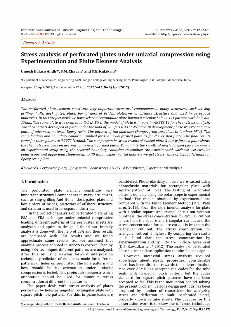
Stress analysis of perforated plates under uniaxial compression using Experimentation and Finite Element Analysis
Umesh Balaso Andh#*, S.M. Chavan# and S.G. Kulakrni#
#Department of Mechanical Engineering, SKN Sinhgad College of Engineering, Korti, Pandharpur Dist- Solapur, Maharastra, India Accepted 25 April 2017, Available online 27 April 2017, Vol.7, No.2 (April 2017)
Abstract The perforated plate element constitute very important structural components in many structures, such as ship grilling, hulls, dock gates, plate, box girders of brides, platforms of offshore structure and used in aerospace industries. In this project work we have select a rectangular plate having a circular hole in 4x4 pattern with hole dia. 17mm. The same plate was created in CATIA V5 & the model of plate is import in ANSYS 14 for shear stress analysis. The shear stress developed in plate under the load of 70 Kg is 0.4377 N/mm2. In development phase we create a new plate of advanced material Epoxy resin. The pattern of the hole also changes from turbulent to laminar [4*4]. The same loading and boundary condition applied for the newly formed plate as for the existed plate. The final results came for these plate are 0.2972 N/mm2. The comparison between results of existed plate & newly formed plate shows the shear stresses goes on decreasing in newly formed plate. To validate the results of newly formed plate we create on experimental setup using the selected boundary condition to conduct the experimental work we use circular polariscope and apply load stepwise up to 70 Kg. In experimental analysis we get stress value of 0.2850 N/mm2 for Epoxy resin plate. Keywords: Perforated plate, Epoxy resin, Shear stress, ANSYS 14 Workbench, Experimental analysis 1. Introduction
1 The perforated plate element constitute very important structural components in many structures, such as ship grilling And Hulls , dock gates, plate and box girders of brides, platforms of offshore structure and structures used in aerospace industries. In the project of analysis of perforated plate using ESA and FEA technique under uniaxial compressive loading, different patterns of the perforated sheets are analyzed and optimum design is found out. Initially analysis is done with the help of ESA and then results are compared with FEA results and we found approximate same results. So, we assumed that analysis process adopted in ANSYS is correct. Then by using FEA techniques different patterns are analyzed. After this by using Newton forward interpolation technique prediction of results is made for different patterns of holes on perforated. The hole pattern and how should be its orientation under uniaxial compression is tested. This project also suggests which orientation should be used for minimum stress concentration at different hole patterns. The paper deals with stress analysis of plates perforated by holes arranged in rectangular plate with square pitch hole pattern. For this, in-plane loads are
*Corresponding author Umesh Balaso Andh is a Research Scholar
considered. Photo elasticity models were casted using photoelastic materials for rectangular plate with square pattern of holes. The testing of perforated plates is done by using the polariscope in experimental method. The results obtained by experimental are compared with the Finite Element Method (R. D. Patil et al, 2015). From the experimental analysis for plate with circular, square and triangular cut out without bluntness, the stress concentration for circular cut out is less than the square and triangular cut out and the stress concentration for square cut out is less than the triangular cut out. The stress concentration for triangular cut out is highest. By comparing the results it is found that, the stress concentration by experimentation and by FEM are in close agreement (D.B. Kawadkar et al, 2012). The analysis of perforated plate has immediate application to tube sheet design.
However successful stress analysis required knowledge about elastic properties. Considerable effort has been directed towards their determination. Moe ever ASME has accepted the codes for the tube seats with triangular pitch pattern, but the codes standard for square pitch patterns have not been accepted so far. This is the motivation behind solving the present problem. Various design methods has been proposed by number of researchers for analyzing stress and deflection in multi perforated plates, properly known as tube sheets. The purpose for this dissertation work is to show the different techniques
Umesh Balaso Andh et al Stress analysis of perforated plates under uniaxial compression using Experimentation and Finite Element Analysis
432| International Journal of Current Engineering and Technology, Vol.7, No.2 (April 2017)
developed by various researchers in the analysis of perforated plates (Prashant Jayavant et al, 2015).
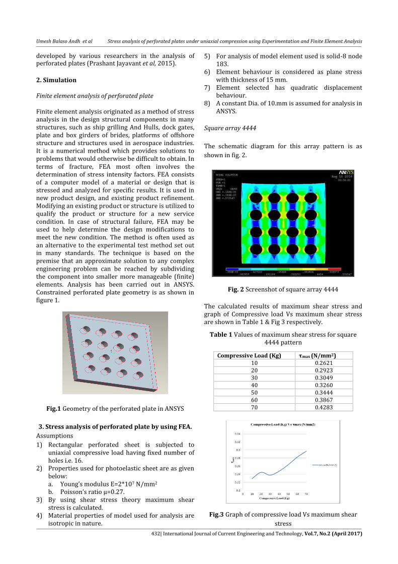
2. Simulation Finite element analysis of perforated plate Finite element analysis originated as a method of stress analysis in the design structural components in many structures, such as ship grilling And Hulls, dock gates, plate and box girders of brides, platforms of offshore structure and structures used in aerospace industries. It is a numerical method which provides solutions to problems that would otherwise be difficult to obtain. In terms of fracture, FEA most often involves the determination of stress intensity factors. FEA consists of a computer model of a material or design that is stressed and analyzed for specific results. It is used in new product design, and existing product refinement. Modifying an existing product or structure is utilized to qualify the product or structure for a new service condition. In case of structural failure, FEA may be used to help determine the design modifications to meet the new condition. The method is often used as an alternative to the experimental test method set out in many standards. The technique is based on the premise that an approximate solution to any complex engineering problem can be reached by subdividing the component into smaller more manageable (finite) elements. Analysis has been carried out in ANSYS. Constrained perforated plate geometry is as shown in figure 1.
Fig.1 Geometry of the perforated plate in ANSYS
3. Stress analysis of perforated plate by using FEA.
Assumptions
1) Rectangular perforated sheet is subjected to uniaxial compressive load having fixed number of holes i.e. 16.
2) Properties used for photoelastic sheet are as given below: a. Young’s modulus E=2*107 N/mm2 b. Poisson’s ratio µ=0.27.
3) By using shear stress theory maximum shear stress is calculated.
4) Material properties of model used for analysis are isotropic in nature.
5) For analysis of model element used is solid-8 node 183.
6) Element behaviour is considered as plane stress with thickness of 15 mm.
7) Element selected has quadratic displacement behaviour.
8) A constant Dia. of 10.mm is assumed for analysis in ANSYS.
Square array 4444
The schematic diagram for this array pattern is as
shown in fig. 2.
Fig. 2 Screenshot of square array 4444
The calculated results of maximum shear stress and graph of Compressive load Vs maximum shear stress are shown in Table 1 & Fig 3 respectively.
Table 1 Values of maximum shear stress for square 4444 pattern
Compressive Load (Kg) τmax (N/mm2)
10 0.2621 20 0.2923 30 0.3049 40 0.3260 50 0.3444 60 0.3867 70 0.4283
Fig.3 Graph of compressive load Vs maximum shear
stress
Umesh Balaso Andh et al Stress analysis of perforated plates under uniaxial compression using Experimentation and Finite Element Analysis
433| International Journal of Current Engineering and Technology, Vol.7, No.2 (April 2017)
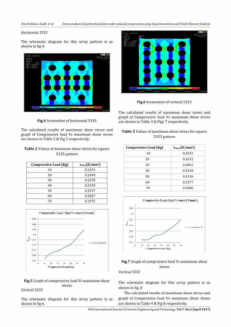
Horizontal 3553 The schematic diagram for this array pattern is as shown in fig 4.
Fig.4 Screenshot of horizontal 5335 The calculated results of maximum shear stress and graph of Compressive load Vs maximum shear stress are shown in Table 2 & Fig 5 respectively.
Table 2 Values of maximum shear stress for square
5335 pattern
Compressive Load (Kg) τmax(N/mm2)
10 0.2293
20 0.2449
30 0.2378
40 0.2478
50 0.2637
60 0.2827
70 0.2972
Fig.5 Graph of compressive load Vs maximum shear
stress Vertical 5335 The schematic diagram for this array pattern is as shown in fig 6.
Fig.6 Screenshot of vertical 5353
The calculated results of maximum shear stress and graph of Compressive load Vs maximum shear stress are shown in Table 3 & Figs 7 respectively.
Table 3 Values of maximum shear stress for square
5353 pattern
Compressive Load (Kg) τmax (N/mm2)
10 0.2631
20 0.2652
30 0.2861
40 0.2918
50 0.3136
60 0.3377
70 0.3696
Fig.7 Graph of compressive load Vs maximum shear
stress
Vertical 5353
The schematic diagram for this array pattern is as
shown in fig. 8
The calculated results of maximum shear stress and
graph of Compressive load Vs maximum shear stress
are shown in Table 4 & Fig 8 respectively.
Umesh Balaso Andh et al Stress analysis of perforated plates under uniaxial compression using Experimentation and Finite Element Analysis
434| International Journal of Current Engineering and Technology, Vol.7, No.2 (April 2017)
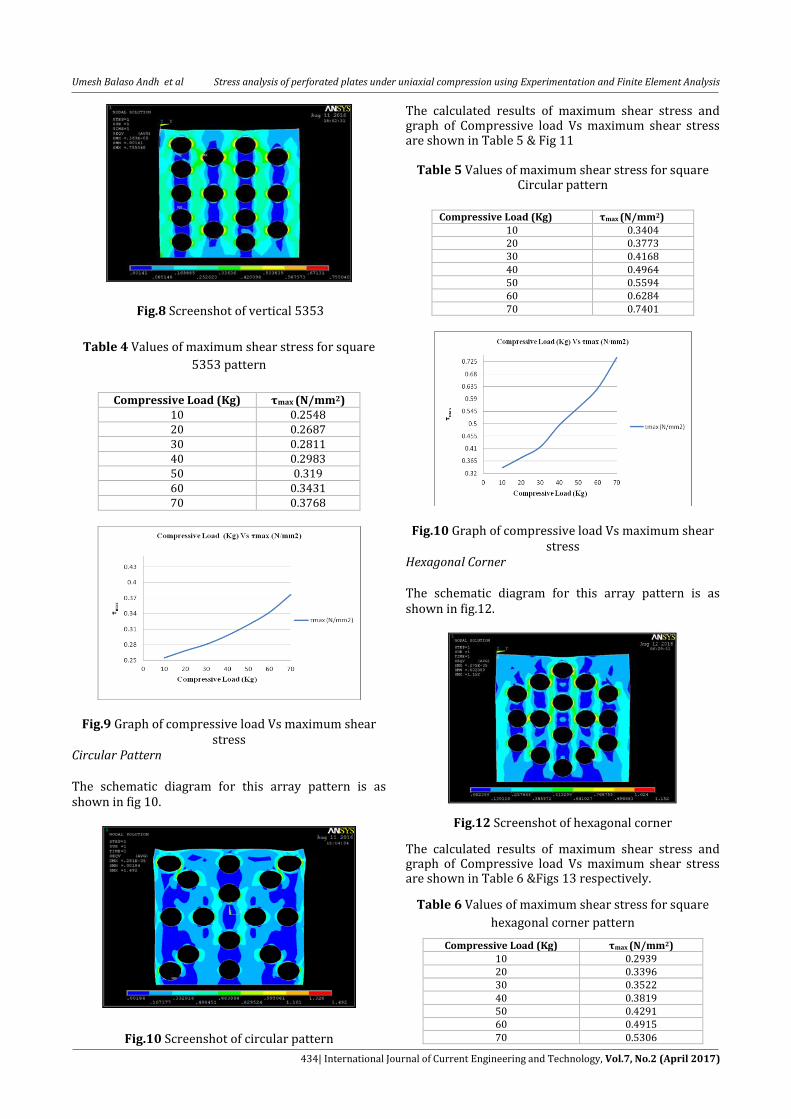
Fig.8 Screenshot of vertical 5353
Table 4 Values of maximum shear stress for square
5353 pattern
Compressive Load (Kg) τmax (N/mm2)
10 0.2548 20 0.2687 30 0.2811 40 0.2983 50 0.319 60 0.3431 70 0.3768
Fig.9 Graph of compressive load Vs maximum shear stress
Circular Pattern The schematic diagram for this array pattern is as shown in fig 10.
Fig.10 Screenshot of circular pattern
The calculated results of maximum shear stress and graph of Compressive load Vs maximum shear stress are shown in Table 5 & Fig 11
Table 5 Values of maximum shear stress for square Circular pattern
Compressive Load (Kg) τmax (N/mm2)
10 0.3404 20 0.3773 30 0.4168 40 0.4964 50 0.5594 60 0.6284 70 0.7401
Fig.10 Graph of compressive load Vs maximum shear stress
Hexagonal Corner The schematic diagram for this array pattern is as shown in fig.12.
Fig.12 Screenshot of hexagonal corner
The calculated results of maximum shear stress and graph of Compressive load Vs maximum shear stress are shown in Table 6 &Figs 13 respectively.
Table 6 Values of maximum shear stress for square
hexagonal corner pattern
Compressive Load (Kg) τmax (N/mm2)
10 0.2939 20 0.3396 30 0.3522 40 0.3819 50 0.4291 60 0.4915 70 0.5306
Umesh Balaso Andh et al Stress analysis of perforated plates under uniaxial compression using Experimentation and Finite Element Analysis
435| International Journal of Current Engineering and Technology, Vol.7, No.2 (April 2017)
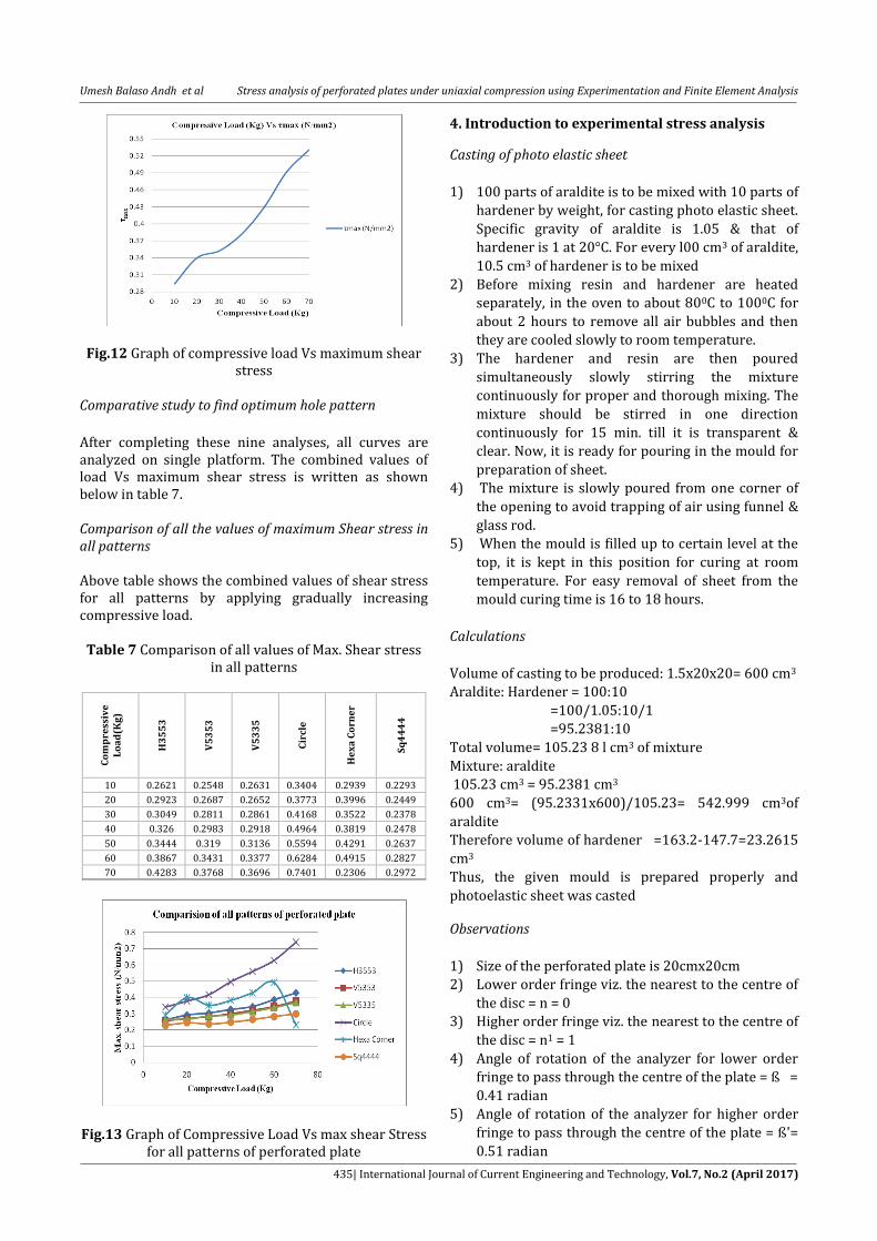
Fig.12 Graph of compressive load Vs maximum shear stress
Comparative study to find optimum hole pattern
After completing these nine analyses, all curves are analyzed on single platform. The combined values of load Vs maximum shear stress is written as shown below in table 7. Comparison of all the values of maximum Shear stress in all patterns Above table shows the combined values of shear stress for all patterns by applying gradually increasing compressive load.
Table 7 Comparison of all values of Max. Shear stress
in all patterns
Co
mp
ress
ive
L
oa
d(K
g)
H3
55
3
V5
35
3
V5
33
5
Cir
cle
He
xa
Co
rne
r
Sq
44
44
10 0.2621 0.2548 0.2631 0.3404 0.2939 0.2293
20 0.2923 0.2687 0.2652 0.3773 0.3996 0.2449
30 0.3049 0.2811 0.2861 0.4168 0.3522 0.2378
40 0.326 0.2983 0.2918 0.4964 0.3819 0.2478
50 0.3444 0.319 0.3136 0.5594 0.4291 0.2637
60 0.3867 0.3431 0.3377 0.6284 0.4915 0.2827
70 0.4283 0.3768 0.3696 0.7401 0.2306 0.2972
Fig.13 Graph of Compressive Load Vs max shear Stress for all patterns of perforated plate
4. Introduction to experimental stress analysis
Casting of photo elastic sheet
1) 100 parts of araldite is to be mixed with 10 parts of
hardener by weight, for casting photo elastic sheet.
Specific gravity of araldite is 1.05 & that of
hardener is 1 at 20°C. For every l00 cm3 of araldite,
10.5 cm3 of hardener is to be mixed
2) Before mixing resin and hardener are heated
separately, in the oven to about 800C to 1000C for
about 2 hours to remove all air bubbles and then
they are cooled slowly to room temperature.
3) The hardener and resin are then poured
simultaneously slowly stirring the mixture
continuously for proper and thorough mixing. The
mixture should be stirred in one direction
continuously for 15 min. till it is transparent &
clear. Now, it is ready for pouring in the mould for
preparation of sheet.
4) The mixture is slowly poured from one corner of
the opening to avoid trapping of air using funnel &
glass rod.
5) When the mould is filled up to certain level at the
top, it is kept in this position for curing at room
temperature. For easy removal of sheet from the
mould curing time is 16 to 18 hours.
Calculations
Volume of casting to be produced: 1.5x20x20= 600 cm3
Araldite: Hardener = 100:10
=100/1.05:10/1
=95.2381:10
Total volume= 105.23 8 l cm3 of mixture
Mixture: araldite
105.23 cm3 = 95.2381 cm3
600 cm3= (95.2331x600)/105.23= 542.999 cm3of
araldite
Therefore volume of hardener =163.2-147.7=23.2615
cm3
Thus, the given mould is prepared properly and
photoelastic sheet was casted
Observations
1) Size of the perforated plate is 20cmx20cm
2) Lower order fringe viz. the nearest to the centre of
the disc = n = 0
3) Higher order fringe viz. the nearest to the centre of
the disc = n1 = 1
4) Angle of rotation of the analyzer for lower order
fringe to pass through the centre of the plate = ß =
0.41 radian
5) Angle of rotation of the analyzer for higher order
fringe to pass through the centre of the plate = ß'=
0.51 radian
Umesh Balaso Andh et al Stress analysis of perforated plates under uniaxial compression using Experimentation and Finite Element Analysis
436| International Journal of Current Engineering and Technology, Vol.7, No.2 (April 2017)
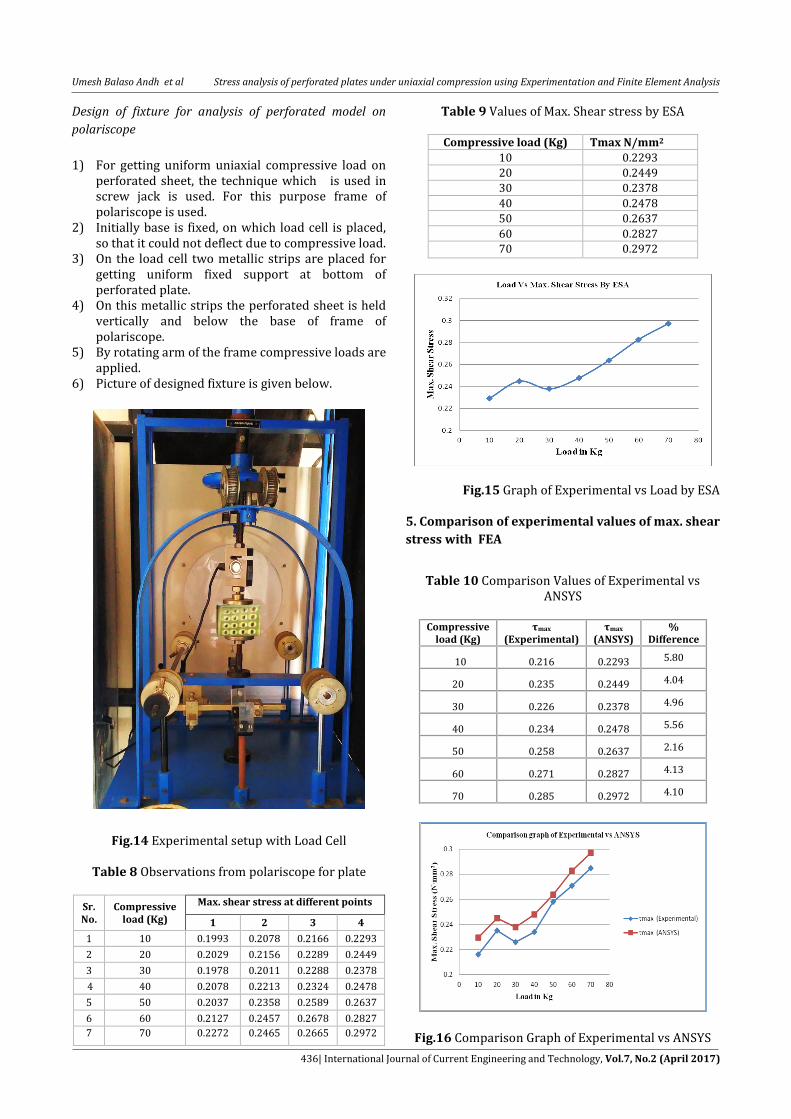
Design of fixture for analysis of perforated model on
polariscope
1) For getting uniform uniaxial compressive load on perforated sheet, the technique which is used in screw jack is used. For this purpose frame of polariscope is used.
2) Initially base is fixed, on which load cell is placed, so that it could not deflect due to compressive load.
3) On the load cell two metallic strips are placed for getting uniform fixed support at bottom of perforated plate.
4) On this metallic strips the perforated sheet is held vertically and below the base of frame of polariscope.
5) By rotating arm of the frame compressive loads are applied.
6) Picture of designed fixture is given below.
Fig.14 Experimental setup with Load Cell
Table 8 Observations from polariscope for plate
Sr. No.
Compressive load (Kg)
Max. shear stress at different points
1 2 3 4
1 10 0.1993 0.2078 0.2166 0.2293
2 20 0.2029 0.2156 0.2289 0.2449
3 30 0.1978 0.2011 0.2288 0.2378
4 40 0.2078 0.2213 0.2324 0.2478
5 50 0.2037 0.2358 0.2589 0.2637
6 60 0.2127 0.2457 0.2678 0.2827
7 70 0.2272 0.2465 0.2665 0.2972
Table 9 Values of Max. Shear stress by ESA
Compressive load (Kg) Τmax N/mm2
10 0.2293
20 0.2449
30 0.2378
40 0.2478
50 0.2637
60 0.2827
70 0.2972
Fig.15 Graph of Experimental vs Load by ESA 5. Comparison of experimental values of max. shear
stress with FEA
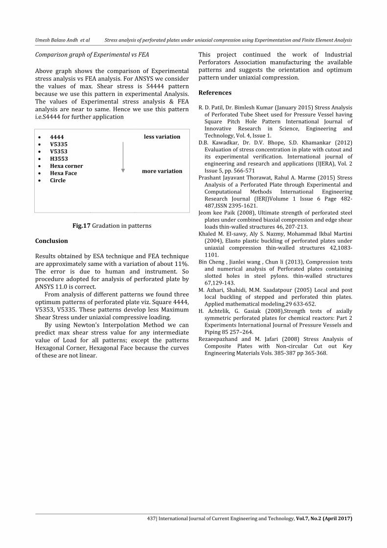
Table 10 Comparison Values of Experimental vs ANSYS
Compressive
load (Kg) τmax
(Experimental) τmax
(ANSYS) %
Difference
10 0.216 0.2293 5.80
20 0.235 0.2449 4.04
30 0.226 0.2378 4.96
40 0.234 0.2478 5.56
50 0.258 0.2637 2.16
60 0.271 0.2827 4.13
70 0.285 0.2972 4.10
Fig.16 Comparison Graph of Experimental vs ANSYS
Umesh Balaso Andh et al Stress analysis of perforated plates under uniaxial compression using Experimentation and Finite Element Analysis
437| International Journal of Current Engineering and Technology, Vol.7, No.2 (April 2017)
Comparison graph of Experimental vs FEA
Above graph shows the comparison of Experimental stress analysis vs FEA analysis. For ANSYS we consider the values of max. Shear stress is S4444 pattern because we use this pattern in experimental Analysis. The values of Experimental stress analysis & FEA analysis are near to same. Hence we use this pattern i.e.S4444 for further application
4444 V5335 V5353 H3553 Hexa corner Hexa Face Circle
less variation
more variation
Fig.17 Gradation in patterns Conclusion Results obtained by ESA technique and FEA technique are approximately same with a variation of about 11%. The error is due to human and instrument. So procedure adopted for analysis of perforated plate by ANSYS 11.0 is correct. From analysis of different patterns we found three optimum patterns of perforated plate viz. Square 4444, V5353, V5335. These patterns develop less Maximum Shear Stress under uniaxial compressive loading. By using Newton’s Interpolation Method we can predict max shear stress value for any intermediate value of Load for all patterns; except the patterns Hexagonal Corner, Hexagonal Face because the curves of these are not linear.
This project continued the work of Industrial Perforators Association manufacturing the available patterns and suggests the orientation and optimum pattern under uniaxial compression. References R. D. Patil, Dr. Bimlesh Kumar (January 2015) Stress Analysis
of Perforated Tube Sheet used for Pressure Vessel having Square Pitch Hole Pattern International Journal of Innovative Research in Science, Engineering and Technology, Vol. 4, Issue 1.
D.B. Kawadkar, Dr. D.V. Bhope, S.D. Khamankar (2012) Evaluation of stress concentration in plate with cutout and its experimental verification. International journal of engineering and research and applications (IJERA), Vol. 2 Issue 5, pp. 566-571
Prashant Jayavant Thorawat, Rahul A. Marme (2015) Stress Analysis of a Perforated Plate through Experimental and Computational Methods International Engineering Research Journal (IERJ)Volume 1 Issue 6 Page 482-487,ISSN 2395-1621.
Jeom kee Paik (2008), Ultimate strength of perforated steel plates under combined biaxial compression and edge shear loads thin-walled structures 46, 207-213.
Khaled M. EI-sawy, Aly S. Nazmy, Mohammad Ikbal Martini (2004), Elasto plastic buckling of perforated plates under uniaxial compression thin-walled structures 42,1083-1101.
Bin Cheng , Jianlei wang , Chun li (2013), Compression tests and numerical analysis of Perforated plates containing slotted holes in steel pylons. thin-walled structures 67,129-143.
M. Azhari, Shahidi, M.M. Saadatpour (2005) Local and post local buckling of stepped and perforated thin plates. Applied mathematical modeling,29 633-652.
H. Achtelik, G. Gasiak (2008),Strength tests of axially symmetric perforated plates for chemical reactors: Part 2 Experiments International Journal of Pressure Vessels and Piping 85 257–264.
Rezaeepazhand and M. Jafari (2008) Stress Analysis of Composite Plates with Non-circular Cut out Key Engineering Materials Vols. 385-387 pp 365-368.