Embed Size (px)
Citation preview
IAEA Consultancy Meeting Vienna, August 24-27, 2010
Stress AnalysisFinite Element Modeling
DOE – NNSAB&W Y-12, LLCArgonne National LabUniversity of MissouriINR – Pitesti
2
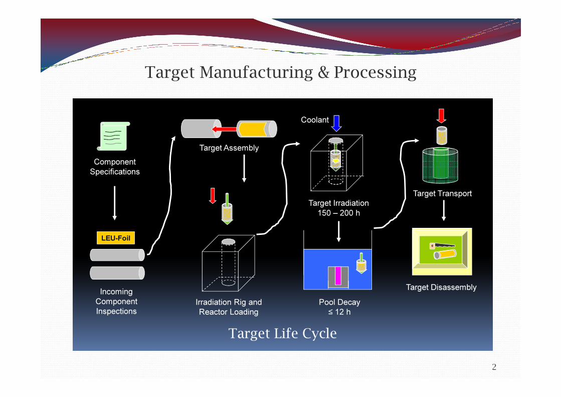
Target Manufacturing & Processing
Target Life CycleTarget Life Cycle
Component Specifications
LEU-Foil
Incoming Component Inspections
Target Assembly
Irradiation Rig and Reactor Loading
Coolant
Target Irradiation150 – 200 h
Pool Decay≤ 12 h
Target Transport
Target Disassembly
Target Life Cycle
LEU-Foil Target Development & Qualification
3
Project Objectives:� Develop a target qualification methodology that is bounding for all Mo-99 target irradiators� Develop target qualification methodology by building upon the annular target design work and
testing previously performed by ANL and ANSTO/CERCA (circa 2004)� Expand upon ANSTO’s “safety case” document set of analyses� Establish max. target LEU-foil mass ( ≥ 32 g U ) - - - determine if achievable� Develop a “Universal” LEU-foil target qualification document� Develop a ”Universal” target failure analysis methodology (failure in reactor containment)� Provide an alternate target geometry (flat plate, curved plate)� Optimize Safety vs. Economics� Goal is to manufacture a safe, but relatively inexpensive target to offset the inherent economic
disadvantage of using LEU in place of HEU� Develop target material specifications and manufacturing QC test criteria
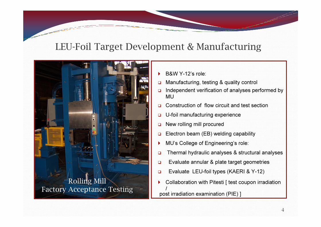
LEU-Foil Target Development & Manufacturing
4
� B&W Y-12’s role:� Manufacturing, testing & quality control� Independent verification of analyses performed by
MU� Construction of flow circuit and test section� U-foil manufacturing experience� New rolling mill procured� Electron beam (EB) welding capability� MU’s College of Engineering’s role:� Thermal hydraulic analyses & structural analyses� Evaluate annular & plate target geometries � Evaluate LEU-foil types (KAERI & Y-12)� Collaboration with Pitesti [ test coupon irradiation
/post irradiation examination (PIE) ]
Rolling MillFactory Acceptance Testing
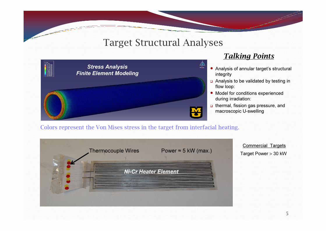
Target Structural AnalysesTalking Points
5
� Analysis of annular target’s structural integrity� Analysis to be validated by testing in flow loop:� Model for conditions experienced during irradiation:� thermal, fission gas pressure, and macroscopic U-swelling
Stress AnalysisFinite Element Modeling
Colors represent the Von Mises stress in the target from interfacial heating.
Ni-Cr Heater Element
Thermocouple Wires Power ≈ 5 kW (max.)Commercial TargetsTarget Power > 30 kW
Target Structural AnalysesNumeric Simulations
6
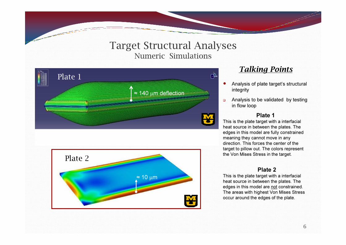
Talking Points� Analysis of plate target’s structural
integrity� Analysis to be validated by testing
in flow loopPlate 1
This is the plate target with a interfacial heat source in between the plates. The edges in this model are fully constrained meaning they cannot move in any direction. This forces the center of the target to pillow out. The colors represent the Von Mises Stress in the target.
Plate 1
Plate 2This is the plate target with a interfacial heat source in between the plates. The edges in this model are not constrained. The areas with highest Von Mises Stress occur around the edges of the plate.
≈ 140 µm deflection
Plate 2≈ 10 µm

LEU-Foil Target Development & Testing
7
Laser Displacement Measurement Test
Section
Electroplating Ni FissionRecoil Barrier to U-foil
≈ 9 µm Nickel on Stainless Steel, 1000x
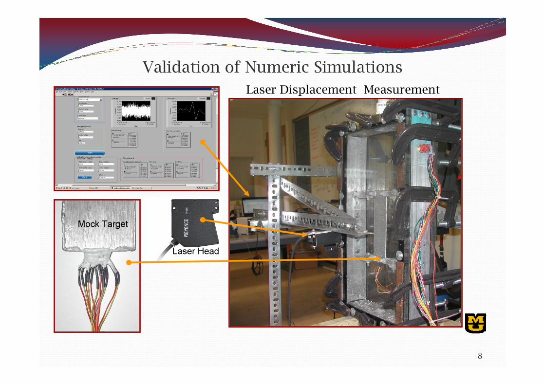
Validation of Numeric Simulations
8
Laser Displacement Measurement
Laser Head
Mock Target

Thermal Contact Resistance Analysis
5
15
25
35
45
55
65
75
85
95
0 4 8 12 16 20 24 28 32 36 40
LEU Temperature (K)
Heat
Flux (
W/cm
2 )
Air Gap (µm)
1670-1770
1570-1670
1470-1570
1370-1470
1270-1370
1170-1270
1070-1170
970-1070
870-970
770-870
670-770
570-670
470-570
370-470
Clad
ding
Air G
ap
Coola
nt
Heat
Flux f
rom
LEU-
foil
350 ºC / 623 ºK550 ºC / 820 ºK
Example: 95 W/cm2
≈ 9 µm
Melting PointU ≈ 1400 °KNi ≈ 1730 °KAl ≈ 930 °K
9

LEU-Foil Target Development & Testing
10
Thickness Variation of KAERI U-Foil Samples
Thickness Variation – 50 µmOther studies suggest up to 100 µm
11
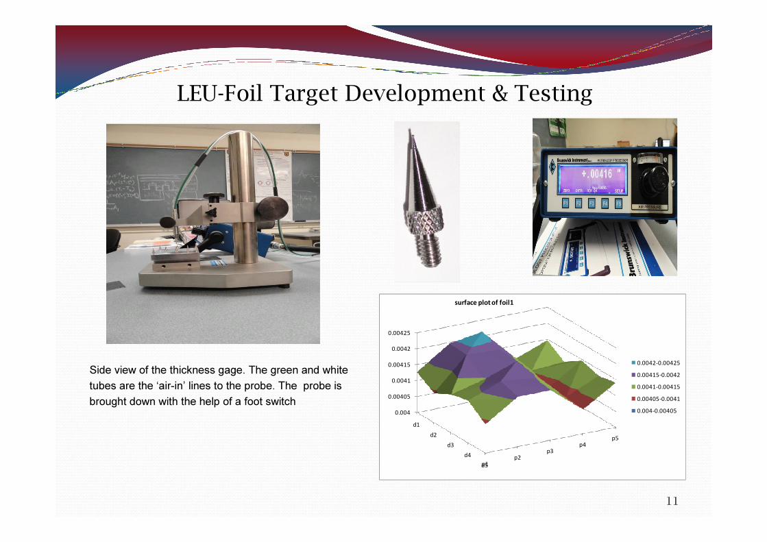
LEU-Foil Target Development & Testing
Side view of the thickness gage. The green and white tubes are the ‘air-in’ lines to the probe. The probe isbrought down with the help of a foot switch
p1p2
p3p4
p5
0.004
0.00405
0.0041
0.00415
0.0042
0.00425
d1d2
d3d4
d5
0.0042-0.004250.00415-0.00420.0041-0.004150.00405-0.00410.004-0.00405
surface plot of foil1

Analytical Input Data Required� In order to develop a conservatively bounding “Safety Case” document, stakeholders
would need to provide reactor specific irradiation data� For example: � max. thermal neutron flux ( ≤ 2.8E14 n/cm2 -s )� max. irradiation time ( ≤ 200 hrs )� % 235U burnup ( ≤ 8% )� target heat flux limit ( W/cm2 )� Containment “free” volume ( m3 )� Depth (from pool surface ) at which targets are irradiated ( ≥ 7 m, 23 ft )� Target cooling period ( ≤ 12 h )� Current transport cask shielding design: total fission product activity at time of
target transport � grams (or mols) of noble gases ( Kr & Xe ) generated during target irradiation� Ideal target dimensions (i.e., size) and LEU-foil mass� Ideal LEU-foil thickness (125 µm [5 mils] – 180 µm [7 mils] ); specific target
power ( W/gU ) increases with decreasing foil thickness ( ≈ 5% per 25 µm ∆ ) � Preferred target geometry ( annular, plate )
12
Target Development & Qualification Philosophy
- - - Food for Thought - - -
�A LEU-Foil target is a Mo-99 production “consumable” with a limited life cycle
�There is no question that it must maintain its structural integrity during irradiation and pool cooling - - - Reactor safety is of first priority
�However, does a Mo-99 production target need to be designed and qualified to the same extent as reactor fuel elements?
13
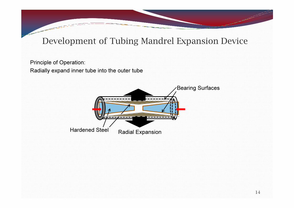
Development of Tubing Mandrel Expansion DevicePrinciple of Operation:Radially expand inner tube into the outer tube
14
Hardened Steel
Bearing Surfaces
Radial Expansion
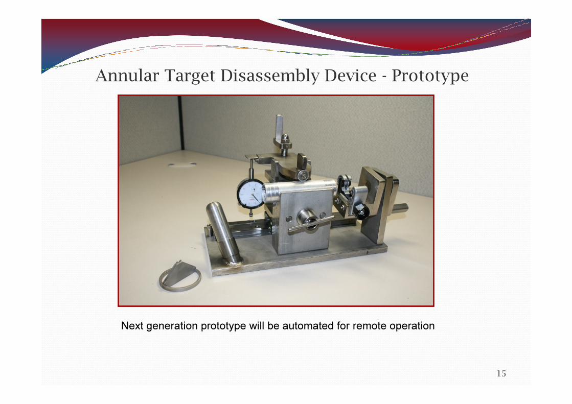
Annular Target Disassembly Device - Prototype
15
Next generation prototype will be automated for remote operation


![Finite Element Modeling for Stress Analysis[R.D.cook,1995]](https://img.pdfslide.us/doc/110x75/547ffaa2b4795978588b45a5/finite-element-modeling-for-stress-analysisrdcook1995.jpg)