Embed Size (px)
Citation preview
•
•
Stress Analysis and Fabrication of Composite
Monocoque Bicycle Frames
By:
Patrick L. Lizotte
Department of Mechanical Engineering
McGill University, Montréal
A Thesis Subrnitted to the Faculty of Graduate Studies and
Research in Partial Fulfillment of the Requirements of the
Degree of Master of Engineering
© Patrick Lizotte 1996
1+1 Nationallibraryof canada
Bibliothèque nationaledu canada
Acquisitions and Direction des acquisitions etBibliographie services Branch des services bibliographiques
39S Welh!"lQlon StreelQnawa. ontanoK,A ON4
395. rue WelllnglonQnawa (Ontano)K'AON4
The author has granted anirrevocable non-exclusive licenceallowing the National Library ofCanada to reproduce, loan,distribute or sell copies ofhisjher thesis by any means andin any form or format, makingthis thesis available to interestedpersons.
The author retains ownership ofthe copyright in hisjher thesis.Neither the thesis nor substantialextracts from it may be printed orotherwise reproduced withouthisjher permission.
L'auteur a accordé une licenceirrévocable et non exclusivepermettant à la Bibliothèquenationale du Canada dereproduire, prêter, distribuer ouvendre des copies de sa thèsede quelqulo: manière et sousquelque forme que ce soit pourmettre des exemplaires de cettethèse à la disposition despersonnes intéressées.
L'auteur conserve la propriété dudroit d'auteur qui protège sathèse. Ni la thèse ni des extraitssubstantiels de celle-ci nedoivent être imprimés ouautrement reproduits sans sonautorisation.
ISBN 0-612-19874-X
Canada

•
•
To my parents, Lise and Georges...
•
•
Abstract
An analytical anù cxperimcntal in\"cstigation \Vas conùucteù to stlldy the ùesign anù
fabrication of carbon liber tr..lck bicycle frames. A linite clement Sofl\v;lre \Vas lIseù for the
geomctry de\"clopment. lan1inate conlïgur..ltion. and for predicting failure using the
maximum stress criteria. A load case and bounùary conditions simulating actual riding
conditions were de\"doped. The stresses in each of the composite layers \Vere found to be
lower than the allowable stresses because of a properly designed geometry and laminate.
Two composite fr..lmes were fabricated using the hand lay-up technique. using
unidirectional and wo\"en carbon fiber pre-preg material o\"er an internai foam core. Using
static testing techniques and comparisons with tr..lditional tubular frames. the carbon lïber
prototypes were shown to be betler in ail rigidity aspects. Combining the experimental and
theoretical results. a good understanding of the critical problems related to composite
monocoque bicycle fr..lffie design was obtained.
•
•
Il
Résumé
L·n..: ':tud..: analytiqu..:..:t ..:xpàii.i.ntal<.: a ':t': Lit..: p"ur ':tudi..:r la <:lln<:..:ptilln ..:t la fahri<:atiLln
J..: y':llls d..: pist..: faits d..: lihr..: J..: <:arhlln..: "Lln,us ..:t fahriqu':s au t..:nn..: d..: <:<.:H": r..:<:h..:r<:h..:.
l'n logi<:id d·d':m..:nts lini,. a ':1': utilis': pLlur 1<.: J,,:\·dllpp<:l1l..:nt d..: la g':Llm':tri..:. du lamin':
..:t pour pr':Jire: 1;1 rupture: ..:n utilisant 1<.: <:ritèr..: J..: <:Llntr.lint..: maximak. L"n sy,tèm..:
J'<.:fforts..:t d'..:nc:l.slr..:m..:nts simulant d..:s conditions d'utilisation a ':t': d':Ydopp.: et uti!i,':.
Les contraintes dans chacuns des pli, sont ainsi obt..:nus et sont intùieure:, aux containtes
p<:mlise, gr.1ce à une g':cm':trie et un laminé hien conçu,. Les cadre:s Je compo,ite sont
f;lbriqu':s en Ulili,ant 1<.: moulage à la main du pr-:impr-:gn': Je libre: de carbone
unidire:ctionnel et tissé ,ur un moul<.: interne de mousse. Les prototypes de libre: de carbone
sont ensuite test':s de façon statique et compar-:s à des cadre:s tr.lditionnels. Les r-:sultats de
ces tests montrent que les cadre:s de carbone sont sup.:rieurs sur tous les plans de la rigidit':.
En combinant les r-:sultals exp.:rimentaux et th':oriques. on obtient une bonne connaissance
des problèmes critiques reli':s aux cadres de \"':Ios monocoques faits de composite.
•
•
III
Acknowledgments
1wish to thank my th.:sis sup.:rvisor Prof. Larry L.:ssard for his wnstant hdp and insight
through this \"ork. AIso sp<:cial thanks to Prof. Jam.:s N.:m.:s for his availability and
guidanc<:. 1 am aIso gr..lt.:ful to th.: t.:chnicians G.:org.: D.:dik. G.:org.: T.:wtik. Gary
Savard and Louis Hu.:ppin for th<:ir g.:n.:rous and r..lpid hdp in th.: many situations which
aros.:. 1 wish to thank the .:xchange students Fabrice Galtone. Christian Bourget. Jcan
Philipp<: Tizi and Richard Dcvall~ of the Ecole Nationale d'Ing~nieurs de Metz (ENlM) in
Fr.lllcc for their hdp in modcl devdopment using tinitc-element analysis. My gr..ltitude also
exrcnds to Philip White for his help in the construction of the 2 prototyp.:s and to Richard
Langlois of the Centre des Matériaux Composites de St-Jérome for allowing us to us.: their
faciliùes for the final composite layup and curing of the two prototyp<:s. Aiso my sinccre
thanks to the many undergr..lduate students who worked on various aspecl~ of this project
such as the curing jig construction. and the staùc jig construction. and to Jerry Chabot for
his work on the statÎC testing of metallic fr.lll1es. 1 also wish to thank Mahmood Shokrieh.
Hamid Eskandari. Louis Brunet. Gémrd Vroomen. Jean-Fmnçois Milelte. Sylvain
Riendeau. Ann-Louise Lock and all the other past and present members of the Composites
Materials Group for their conùnued help. laughter and support. 1 wouId also like to thank
ail my friends: Martin. Nicolas. Louis. Yvan. Pierre. Pierre-André. Stéphal'':. Nathalie.
Fr.lncois. Mathieu. Matthieu. Paul. Benoit. Zaz. Dave. Sébasùen. Claude. Marie-Josée.
Jocelyn. and ail the ones l forget. who during the ùme 1have spent doing this work. stood
by closely and conùnually helped me to move forward. Et merci particulièrement à toi Julie
qui a ilIunùné ma vic durant le sprint final. La.~t but certainly not least. sinccrc thanks to
my parcnl~ Lise and Georges. my sister Martine and the !"cst of my family who have
conùnually encoumged and supported me in anything 1 dived into. Thanks again to
everyone.
•
•
Table of Contents
Abstr.lct
R~sum~
Acknowledgments
List of Symbols
List of Figures
List of Tables
Chapter 1: Iptroduction
I.l Objective
Chapter 2: Literature Review
2. J R~view of Bicycle Fmme History
2.: Review of Fmme Building Materials2.2.1 Wood ~2.2.2 Steel2.2.3 Aluminum2.2.4 Titamum2.2.5 Magnesium2.2.6 Plastics2.2.7 Composites
2.3 Review of Carbon Fiber Fmmes2.3.1 Carbon Fiber Tube and Lug Designs2.3.2 Monocoque Diarnond Shape Carbon Fiber
Fmmes2.3.3 Bearn Bikes2.3.4 True Monocoque Shapes2.3.5 Summary ofCurrent Carbon Fiber Fmmes
2.4 Review of Bicycle Fmme Stress Analysis
2.5 Review of Manufacturing Methods2.5.1 Wet Layup2.5.2 Prepreg Internai Bladder2.5.3 Resin Tmnsfer Moulding (RTM)25.4 Therrnoset Prepreg - Vacuum Bagging2.5.4 Therrnoplasùc
11
111
viii
Xl
1
66799121313
151516
182022
242525262728
IV
•
•
Chapter 3 : Traditional Frames
~"l Rationale for Modeling and Testing Tr.lditional Fr.lmes
~"2 Finite Element Analysis of Tr.lditional Fr.lmes
~"~ Experimental Description
3.-1 Experimental and Theoretieal Techniques forTraditional Fr.lmes
3.5 Finite Element and Experimental Results
Chapter 4: Composite Frame Design
4.1 Introduction
4.2 Finite Element Analysis of the Composite Frames4.2.1 Geometrv4.2.2 Material and Laminate Contigur.ltion
4.2.2.1 Laminate Contigur~tion of Prototype 14.2.2.2 Laminate Configur.ltion of Prototype 24.2.2.3 Laminate Configur.ltion of Prototype 3
4.2.3 Loading and Boundary Conditions4.2.3.1: Starting Hypothesis of Load Case
Derivaùon4.2.3.2: Problem Steps4.3.3.3: Powers Involved4.2.3.4: Calculation of pedal :oads4.2.3.5 Considering the Complete Bicycle4.2.3.6 Ca!::ulation of the Fr.trne Torsion
Forces on the Handlebars4.2.3.7 Boundary Conditions
4.2.4 Stress Analvsis Results4.2.4.1 Prototype 14.2.4.2 Prototype 24.2.4.3 Prototype 3
Chapter 5: Composite Frame Fabrication and Testing
5.1 Introduction
5.2 Rationa!e for Manufacturing Method
5.3 Fabrication of Prototype 15.3.1 Foarn5.3.2 Foarn Adhesives5.3.3 Inserts5.3.4 Curing Jig5.3.5 Foarn-Alu:ninum Adhesive5.3.6 Carbon Fiber Materia!5.3.7 Maleria! Orientation
'"
29
29
29
30
3:!
35
39
39
39
424445464748
4848505155
5657586266
70
70
70
7171727274757576
•
•
='.3.S Vacuum Ba~~in~5.~.t) Curing .......5.3.10 :-'lass-Prop~rti~s of Prototyp~ 15.~.11 Conclusions and Impro\'~l1l~nts for Protl)typ~ 1
5... Elbri<:aiion of Protl1typ~ 25 1 Foam5 2 Foam Adh~siws
5 ~ lns~rts
5 Foam-Aluminum Adh~si\'~
5 .5 Int~mal Shifting Cable5 6 Carbon Fiocr :'vÏat~rial5 7 Mat~rial Ori~ntaiion
5.-4.8 Vacuum Bagging5 9 Curing ---5 10 Final Ass~mbly of Prototyp~25 11 Ma." Pro~rti~s of Prototyp~ :::5A.12 lmpro\'~m~ntsand Conclusions to Prototyp~ :::
5.5 Composite Fnune Testing5.5.1. Prototype 15.5.2 Prototy~ 2
5.6 Summary
Chapter 6 : Conclusions
Chapter 7: Recommendation for Further Research
Publications Resulting from this Work
References
\,
7{)
/ 1
Î~
7X
SOSOSISiS485S5s585s68788SS
898991
92
93
95
97
98

•
•
List of Svrnbols~
c : StrainCi : StressCi"Xl~ : Stress at 1aaN force(l) : Anaular velocitv
~ .A : AreaC : Couple at the bottom bracketC, : Aerodynamic drag coeftïcientE : Young's ModulusEo : Wheatstone bridge outputEo. loIal : Wheatstone bridge total outputE, : Suppl)' voltageF : ForceF, : Load applied by the front wheel on the frameF:! : Load applied by the rear wheel on the frameFp : Downward force on pedalsF, : Upward force on the pedalsFwiod : Wind resistancep : Air densityP : PowerPair : Power lost due to air resistancePc)'c1is! : Power input l'rom cyclistPtolo' : Total powerr : RadiusR, : Load on front wheelR:! : Load on rear wheelS : Bike + cyclist frontal areat : TimeT : Pulling force on handlebarsTI: Pulling force from the rider's right handT, : Pulling force l'rom the rider's left handW : Weight of the rider
•\111
List of Figures
Chaptcr 2Figurc ~.l: Lc(,)narlio D~ \ïnl...-ï s Bii..'-YL'Ic.: frlllll the..' Clldex .·\jhl1ltÎclf.\ p..'
Figur~ 2.2: Th~ DraisiClll/c l' ..
Figur~ 2.:;: Th~ (}rdil/arr Bi~yd~ l' ..
Figur~ 2...: Starl~y Sa/'·I.\· Bkyd~ p. :'-
Figur~ 2.5: Bamboo Fram~ l'. 6
Figur~ 2.6: Traditional Diamond Shape Slrlll;llIr~ p. i'
Figur~ 2.7: Ba~i~ Dim~n~ion~ of Traditional Fram~' p. 1.'
Figu~ 2.1.': ;-"lat~rial ~n~iti~~ of 5 Fram~ Building "lalcrials p. 10
Figu~ 2.9: Specilïc yloduli of 5 Framc Building "lal~rials 1'.11
Figu~ 2.10: Specitïc Yidd Str~nglh of 5 Fram~ Building "lat~rial, 1'.11
Figu~ 2.11: Prie.: per Kilogram of ylat~rial of 5 Fram~ Building "Iat~rials 1'.12
Figur~ 2.12: TREK Carbon Tub<: and Aluminum Lug ~~ign 1'.16
Figu~ 2.1:;: K~~trel 500SCI Bicyd~ Fram~ without a Scat Tub<: 1'.17
Figure 2.14: Corima Bicycl~ Frame p.li'
Figu~ 2.15: ZIPP B~am Bik~ 1'.19
Figure 2.16: Pinard10 511"0rd 1'.21
Figurc 2.17: Lotu~ Sport 11 0 Fram~ 1'.22
Figu~ 2.18: Hotta Bicyd~ 1'.22
Figu~ 2.19: Internai Bladder Techniquc 1'.26
Figure 2.20: RTM Proce~~ 1'.27
Chapter 3
•
Figure 3.1: Loading Cases
Figure 3.2: Static Bicvcle Frame Testing Jig... .. ... ...Figure 3.3: Load Ccli Calibration Curve
Chapter 4
Figure 4.1: Fr.une Geometrie~ of Three Composite Monocoque Prototypes
Figure 4.2: uel Regulated Dimensions
Figure 4.3: Direction of the O· Vector
1'.31
p.33
1'.35
pAO
l'AI
1'043
•
•
Figure 4.4: Finite-Element Mesh and Laminate Locations for Prototype 1
Figure 4.5: Finite-Element Mesh and Laminate Locations for Prototype 2
Figure 4.6: Finite-Element Mesh and Laminate Locations for Prototype 3
Figure 4.7: Chain Drive
Figure 4.8: Forees Acting on the Bicycle
Figure 4.9: Front Wheel Free Body Diagram
Figure 4.10: Rear Wheel Free Body Diagram
Figure 4.1 1: Handlebar Forces
Figure 4.12: Riding Load Case
Figure 4.13: Riding Restraint Locations
Figure 4.14: Shear Stress Contours for Prototype 1. Layer 3
Figure 4.15: X-Nonnal Stress Contours for Prototype 1. Layer 1
Figure 4.16: Y-Nonnal Stress Contours for Prototype 1. Layer 1
Figure 4. 17: Out-of-Plane Displacement Contours for Prototype 1
Figure 4.18: Prototype 2 - XY-Shear Sn-..sses at BOllom Bracket Region. Layer 3
Figure 4.19: Prototype 2 - X-Nonnal Stress. Layer 1
Figure 4.20: Prototype 2 - Y-Nonnal Stress. Layer 1
Figure 4.21: Displacement Contours for Prototype 2
Figure 4.22 : Maximum X-Stress for Prototype 3
Figure 4.23: Maximum Y-Stress for Prototype 3
Figure 4.24: Maximum XY-Shear Stress for Prototype 3
Chapter 5Figure 5.1: Prototype 1 in the Curing Jig
Figure 5.2: Aluminurn Headset
Figure 5.3: BOllom Bracket
Figure 5.4: Rear DropoulS
Figure 5.5: Vacuum Bagging of Prototype 1
Figure 5.6: Curing Cycle
Figure 5.7: Completed Prototype 1
Figure 5.8: Head Tube Cylinder
Figure 5.9: Head Tube Plate
Figure 5.10: Bollom Bracket Insert
Figure 5.11: Scat Tube Insert
p.45
p.46
p.47
p.50
p.51
p.52
p.S3
p.55
p.56
p.57
p.S9
p.59
p.60
p.61
p.63
p.63
p.64
p.64
p.67
p.68
p.69
p.72
p.73
p.73
p.74
p.76
p.77
p.79
p.82
p.82
p.83
p.84
IX
•
•
Figure 5.12: Proto. 2- Prepreg Application
Figure 5.13: Proto. 2- Release Film
Figure 5.14: Vacuum Bag Applied to the FrJ.me
Figure 5.15 : Finished Prototype 2
p.S6
p.S6
p.S6
p.89
x
• List of tables
Chapter 3
xi
Table 3.1: Finite Element and Experimental Resull~ for Metallie Fmmes
Table 3.2: Errors Between the Finite Element and Experimental Results
Table 3.3: Steel F=e Tests Results
Chapter 4
p.35
p.36
p.37
Table 4.1: Prototype Dimensions pAl
Table 4.2: Materia! Properties for Unidirecùonal and Woven Materials Used pA3in this Study
Table 4.3: Riding Restr:l.ints p.57
Table 4.4: Maximum Failure Index for Each Layer of Prototype 1 p.58
Table 4.5: Maximum Failure Index for Each Layer of Prototype 2 p.62
Table 4.6: Bonom Bracket Displacement with and without Reinforcement p.65
Table 4.7: Maximum Failure Index for Each Layer of Prototype 3 p.66
Chapter 5
•
Table 5.1: Mechanica! Properties of the Foam Used for Prototype 1
Table 5.2: Properties of the AOCHEM High-Strenght Epoxy
Table 5.3: Summary ofWeights for Prototype 1
Table 504: Components
Table 5.5: Summary ofWeights for Prototype 2
Table 5.6: FEA and Experimenta! Results for Prototype 1
Table 5.7: FEA and Experimental Results for Prototype 2
p.71
p.75
p.78
p.87
p.88
p.90
p.91
•
•
Chapter 1
Introduction
Thc usc of advanccd compositc matcrials is bccoming incrcasingly common. Thcy arc uscd
in numcrous applications r.lllging from acrospacc producl' to sports equipmenl. The
sporting goods industry in particular has turncd to advanced composites rccently in sports
such as cycling. hockey. and golf. The cycling industry adopted composites more than 10
years ago in the construction of high performance frames. The use of advanccd composites
materials in this industry has led to changes in the materials. gcometry and construction
technique of bicycle frames. Advanced composites arc bcing used in fr..une construction
because they allow improvemenlS in weight. stiffness. strength. and aerodynamics.
Bicycles have been part of everyday lue for more than 100 years now. They constitUle a
vital means of lI".IlIsportation for sorne. a pastime for others. and a high level competition
machine for a few. International racers are continually seeking frames which perform
bctter in order to ultimately achieve higher speeds for the same amount of frame energy
input. To achieve this goal. advanced composite materials have bcen used in the making of
high tech frames for sorne years now. However. in order to design and manufacture a
frame with these materials. a thorough engineering knowledge of composite materials.
combined with a means of analyzing a structure as complex as a bicycle frame. is essential.
1.1 Objective
The fIrst main goal of the rcsearch was to understand composite frame design through fInite
element analysis. This analysis was helpful for the determination of strength and stiffness
parameters for a frame without actually building it. The stiffness rcsults were then
•
•
compared with a data bank of cxisting tr~ditional diamond shape fr.lmes made of steel and
aluminum in ardcr to make sure that the stiffnesses (torsion. in-plane. out-of-plane) were
improved. The second main goal was the development of a manufacturing technique for
composite prototype frames. Two monocoque carbon liber frames were constructed using
this technique. After the composite frames were constructed. the)' were statically tested to
compare their respective stiffnesses with thcir finite element models.
•
•
Chapter 2
Literature Review
2.1 Review of Bicycle Frame History
It is believed that people have been thinking about building human powered vehicles since
the fifteenth century. A sketch named Codex AtlanticlIs [1] shown in Figure 2.1 and
attributed 10 Leonardo Da Vinci shows a device resembling a bicycle with pedals. a crank
and a chain drive connected to the rear wheel. This vehicle however did not have steering.
henee would have been unstable and thus eould not have been ridden.
Figure 2.1: Leonardo Da Vind's Bicycle from the CodexAtlanticus [1]
By the beginning of the 18oo's, unsteerable two-wheelers referred to as hobby horses
appeared in England [2]. The problem with these machines is that they could not be
balanced going down a hill al high speed as they could not be steered. Thus possibly the
most important invention in bicycle frame design was made by the German Karl Von Drais
•
•
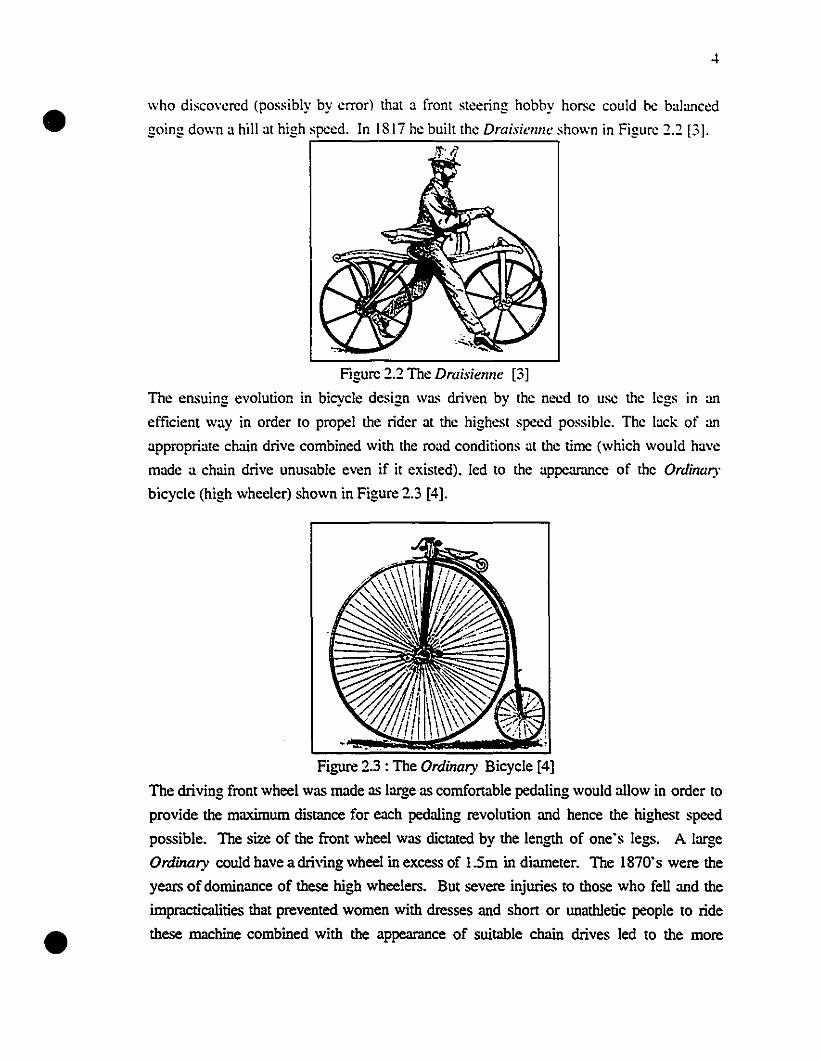
who disco\"ercd (possibly by error) that a front steering hobby horse couId he balanccd
going down a hill at high spced. In 1817 he built the Draisienne shown in Figure 2.2 [3].ri,: 1,
Figure 2.2 The Draisienne [3]
The ensuing evolution in bicycle design was driven by the need to use the legs in an
efficient way in order to propel the rider at the highest speed possible. The lack of an
appropriate chain drive combined with the road conditions at the time (which wouId have
made a chain drive unusable even if it existed). led to the appeamnce of the Ordinary
bicycle (high wheeler) shown in Figure 2.3 [4].
Figure 2.3 : The Ordinary Bicyele [4]
The driving front wheel was made as large as cornfortable pedaling would aIlow in order to
provide the maximum distance for eaeh pedaIing revolution and hence the highest spced
possible. The size of the front wheel was dietated by the length of one's legs. A large
Ordinary couid have adriving wheel in excess of 15m in diameter. The 1870's were the
years of dominance of these high wheelers. But severe injuries to those who fell and the
impr.ICtÎcaIities that prevented women with dresses and short or unathletic people to ride
these machine combined with the appearance of suitable ehain drives led to the more
•
•
5
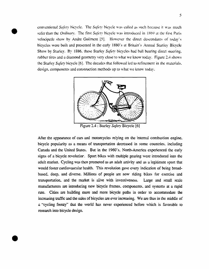
convcntional Safery hicyclc. The Sakry hicycle was ealieJ as such hecause it was much
safer than the Ordinary. The liN S,(/i:ry hicycle was introJuceJ in 1S69 at the lirs! Paris
velocipede show hy Andre Guilment [5J. However the Jirect JesccnJants of toJay's
bicycles were built and presented in the early 1880's at Britain's Annua! Stanley Bicycle
Show by Starley. BC' 1886. these Starlcy Safery bicycles had hall bcaring direct steering.
rubber tires and a diamond geometry very close to what we know today. Figure 2... shows
the Starlcy Safery hicycle [6]. The decades that followed Icd to retinement in the materials.
design. components and construction methods up to what we know today.
Figure 2.4: Starley Safery Bicyele [6]
After the appeurJJ1ce of cars and motoreycles relying on the interna! combustion engine.
bicycle popularity as a means of transportation dccreased in sorne countries. including
Canada and the United States. But in the 1960·s. North-America experienced the carly
signs of a bicycle reVOIUliol". Sport bikes with multiple gearing were introduced into the
adult market. Cycling was then promoted as an adult activity and as a legitimate sport that
wouId toster cardiovascular hcalth. This revolution gave every indication of bcing broad
based. deep. and diverse. Millions of people arc now riding bikes for exereise and
tmnsportation. and the market is alive with inventiveness. Large and small scale
manufacturers arc introducing new bicycle f=es. components. and systems at a mpid
mte. Cilies arc building more and more bicycle paths in order to accommodate the
increasing traffic and the sales of bicycles arc ever increasing. We arc thus in the middle of
;:. "cycling frenzy" that the wodd has never experienced before which is favol".lble to
research into bicycle design.
•
•
6
2.2 Review of Frame Building Materials
Throughout thc ycars. fr.unc building matcrials hayc cyolycd l'rom what wc now think as
ycry primitivc matcrials to space agc matcrials which wcre unknown to our socicty only 30
years ago. It is this improyement in materials which allowed to the greatest extent the
evolution in bicycle fr.unc design. This section will rcYiew most of the fr.une building. ~ ~
materials which havc been used in the past. It will show the adyantages and disadyantages
of the different materials and explain the apparition and disappcar.ll1ce of sorne of thcm.
This analysis will help to r.ltionalize the use of carbon liber material for use in this project.
2.2.1 Wood
wcod was used in the very first bicycle frames produced. Von Dmis' Draisienne and most
other hobby horses in the 18oo's were made of wood [7]. Since a minimum stiffness was
required in order to prevent enormous bending and potential collapse. hcavy wood was
otien used resulting in very heavy structures. This combincd with the tremendous work
required to shape the wood made designers and builders quickly realize that this material
was not the solution. even though sorne good wood fr.uncs were successfully built.
Around the 1870·s. metal construction becarne dominant. but wood continued to be used
spomdically in the construction offrames. rirns. and mudguards even until the 1930·s. At
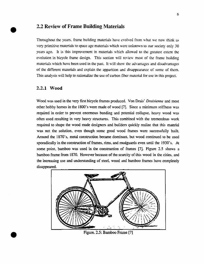
sorne point. bamboo was used in the construction of fr.unes [7]. Figure 2.5 shows a
bamboo frame l'rom 1870. However because of the scarcity of this wood in thc cities. and
the increasing use and understanding of steel. wood and bamboo fr.lffies have completely
disappeare,..;.d_.-----------------------,
•..-Figure. 2.5: Bamboo Frame [7]
•
•
2.2.2 Steel
Withoul lju.:stion. th.: us.: of st.:d in th.: past c.:ntury of hicyck fram.: construction h'IS hc.:n
domin.lOl. Many dil'f.:r.:nt alloys of st.:d ranging l'rom lo\\'-carhon sl.:ds for in.:xp<:nsiv.:
fram.:s to propri.:tary st.:d alloys of chrom.:-mclyhd.:uum-mangan.:s.: for th.: b.:st
comp<:tition fram.:s hav.: b.:.:n us<:d. Curr<:ntly. in.:xp.:nsiv.: fr.lm.:s al"<: mad.: l'rom slr.light
gaug.: tub.:s forrn.:d l'rom st.:d strips. roll<:d and \\'dd<:d along th<: s.:am and lat.:r wdd.:d to
th.: oth.:r tub.:s of th.: fr.ln1':. B<:ll.:r fr.ln1':s ar.: mad<: l'rom s<:amkss llIocs. dr.lwn thinn<:r in
th.: middk than Olt th.: .:nds (bulling) and silv.:r braz.:d into dos<: littings tap<:r.:d Olt th.: llIOC
int.:rs.:ctions. Th<: bUlling of llIOCS is now consid.:red a sci.:n.:.: and tuoc manufactur.:rs
hav<: devdop<:d doubk and triple-bulled tuocs as weil as cir.:umfer.:ntially bUll.:d tuocs
(differcntial shape bUlling) [SI in ord<:r to allow material to be present on1y where it is really
required. Fr.ln1e build<:rs appreciate ste.:rs user-friendlin<:ss. Il oftèrs so many variabks
of dianleter. wall thickn.:ss. shap<: and metallurgy that it is almost possible to tune the
riding of a st.:.:l fmme to th.: rid<:r"s d<:sire. Tubing manufacturers such as Tange.
Reynolds. and Columbus have a complete selection of tuoc sets of different cross section
and using different alloys. As in the case of other metallic materials. the rigidity and weight
of a fr.lmeset is driven by the shap<: of the tuocs while the strength is dictated by
metallurgy. heat treatment. and/or mechanical cold working. The strongest bicycle st.:.:l
availabk is the French-made EXCELL. It has a tensile strength of more than 13S0MPa.
Among the advantages of using steel includes the fact that it is ideal for custom design. as
diftèrent tubesel~ can be chosen to provide different riding char.lcteristics for each rider.
Steel also possesses tr.lditional re.luty and can in cel1ain cascs highlight beautiful
cr.lftsmanship. Aiso. steel has remained relatively inexpensive and readily available over
the years. Steel fr.ln1es do not l'ail cata.~trophically without indication and they possess the
attr.lctive propeny of having afatigue limit. Afatigue limit is detined as the stress level
below which a material will never l'ail under fatigue loading. It reveaL~ the region close to
l'allure with cr.lcks that widen slowly in order to aIIow for an early detection of possible
l'ailure. If it does break. il is very easily repaired by heating a few joints. popping out the
damaged tube and replacing it with a new one. AlI in ail steel is a very convenient frame
building material. but beeause of its high density. it is tied to the diamond shape frame
design and in this way is condernned to fr.ln1e shapes and geometries that go back to the
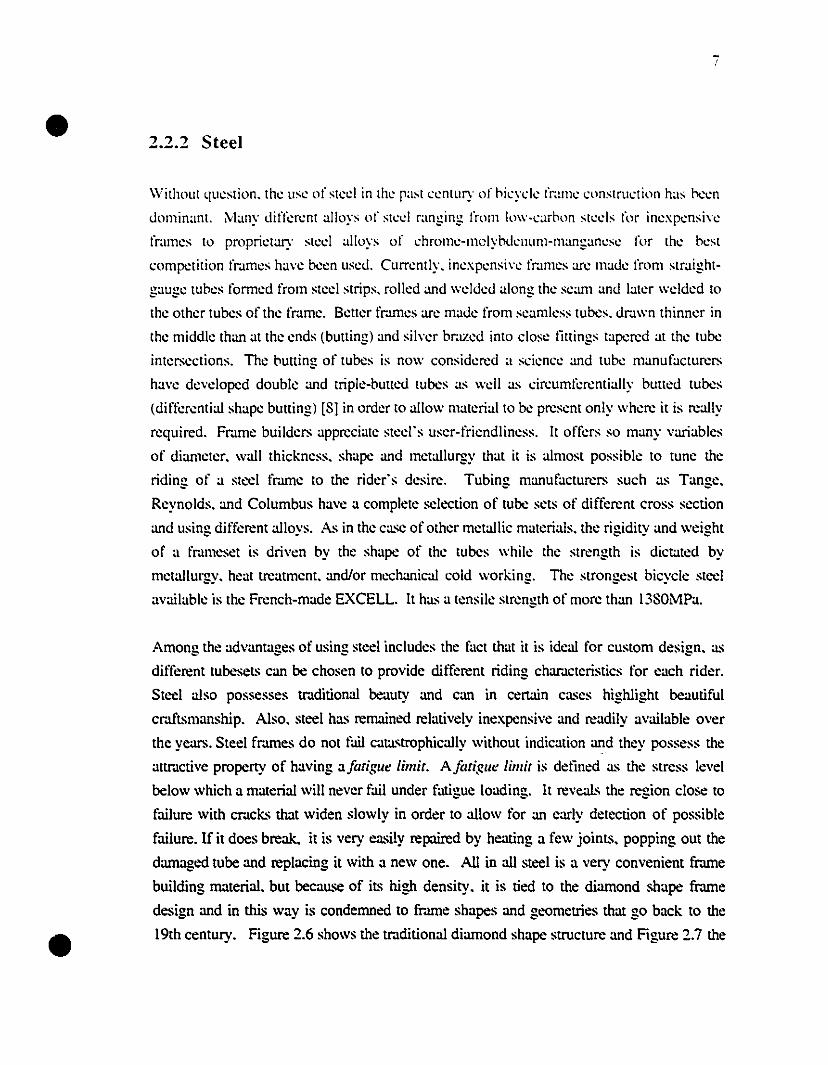
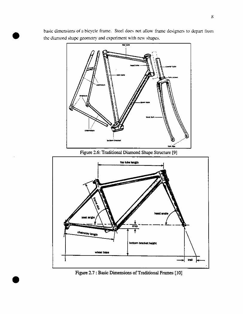
19th century. Figure 2.6 shows the traditional diamond shape structure and Figure 2.7 the
1------
_....
/~'I---""
'r_....
-
•
Figure 2.6: Traditional Diamond Shape Structure [9]
•--
Figure 2.7: Basic Dimensions of Traditional Frames [10]
•
•
2.2.3 Aluminum
The tirst experimentation wilh aluminum fr.lmes oceurreu in the 189(l"s [III. The carly
frames were made l'rom cast aluminum. The tubes were joineu tog..:ther with lllgs as the
wcluing of aluminum was not well known al that time. Aluminllm tubes arc now brazeu.
wclueu or auhesiYclly bonded togelher. Sinee aluminum has a modulus km'Cr than sted.
oyersize tubes may be rcquircd in arder ta proyide a rigidity compar.lblc lo a sted fr.une
[12]. Howeyer because of its lower density. eyen larger diameters and wall thieknesses do
not result in a heaYier fr.lme. As wc incrcase the diameter of the tube the rigidily incrca.ses
to the 4th power of the diameter while the weight increa.ses following the square of the
diameter. Hence it is possible to ootain a rigid and light thune with a1uminum. E;lrly.
poorly designed aluminum tr.101es helped to build a bad reputation for aluminum frames.
ln facto carly aluminum fr.101es tended to l'ail at the tube joints l'rom improper wclding or
bonding and also l'rom fatigue failures a.s aluminllm ha.s no fatigue lilllit a.s is the ca.se with
stecl and titanium. The fact that this material does not have a jiltiglle lilllit requires the
frounes to be slightly overdesigned in order to compensate for this property of the material.
Aluminum is relatively inexpensive. light and adequatcly strong. One of the major
advantages of a1uminum over steel fr.101es is that it is non-corrosive. If properly designed
and built. a1uminum fr.101es can be a.s stiff and lively as steel fr.101es and are now among the
lightest fr.101es on the market. However. as opposed to steel thmes. these tr.lOleS are not
easily repaired and do not look !r.lditional with their often oversized tubes. As with steel.
a1uminum is relatively dense compared to composites and is thus tied to the tr.lditional
diamond shape structure. It would be pr.lctically impossible to depan l'rom the !r.lditional
diamond shape structure while still using a1uminum.
""4T' ._._. Itamum
The first use of tit::...ium in frame construction occurred in the early 1970·s. Titanium
offers bicycle designers a material 62% stiffer than aluminum but 42% lighter than steel
[12]. Titanium fr.101es are anlongst the lightest fr.101es on the market at the present time.
Titanium fr.101es are usually made l'rom commercially pure titanium (0.2% oxygen added to
pure titanium) or from 3A112.5V (3% a1uminum and 2.5% vanadium) a1loy tubes. These.
tubes are usually bought from aircraft and chemical company suppliers which sell these
tubes usually as corrosion resistant plumbing for these industries [13]. Figures 2.8. 2.9•
•10
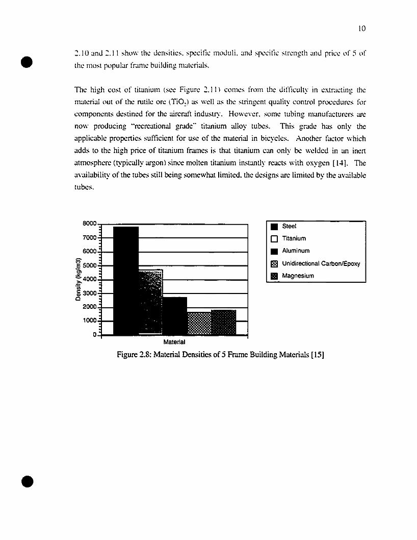
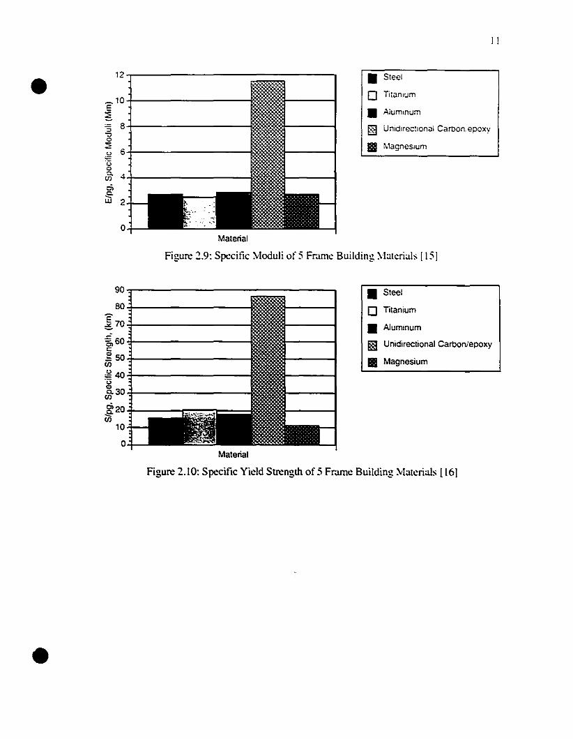
2.10 anJ 2.1 1 show th~ J~nsiti~s. spc~ili~ moJuli. anJ spc~ili~ str~ngth anJ pri~~ of:; of
th~ mosl popular fram~ building mat~rials.
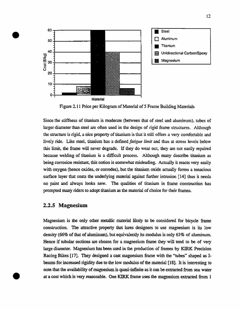
Th~ high cost of tilanium (s~e Figure 2.1 1) comes from th~ Jirticulty in ~xtr;lcting Ih~
material out of the rutile ore (TiO,) as weil as the slring~nt qualily control procedures for
components destined for the aircr..l!i industr:'. Howev~r. sorne tubing manufacturers arc
now producing "recrcational gr.lde·· titanium a1loy tubes. This gr.lde has only the
applicable propcnies suflicient for use of the material in bicycles. Another factor whieh
adds to the high pricc of titanium lr.ll1les is that titanium can only be welded in an inen
atmosphere (typically argon) sinee molten titanium instantly rcacLs with oxygen [141. The
availability of the tubes still being somewhatlimited. the designs arc limited by the available
tubes.
Material
Figure 2.8: Malerial Densities of 5 Fr.ll1le Building Malerials [15]
•
8000."..--===::--------------,
7000
6000
~5000
~4000~~ 3000c
2000
1000
o
• Steel
o Titanium
• Aluminum
!1l!I Unidirectional Carbon/Epoxy
Il Magnesium
Il
12 • Steel• 0 Titanlum_10c • Alumlnum~
"3 8~ UnidlreC!IOnal Carbon. epoxy
"""0::;; lIlll ~'agneslum
g 6,:;
'"0- 4Ul
0>
~ 2
0Malerial
Figure 2.9: Speeitie Moduli of 5 Fr.lmc: Building. :'.lalc:rials [15]
90~--------------~
80.;...---------Il!
~ 70 .;...----------Il!,5 60.;...--------0>cg 50-1--- _Ul
.g 40-'1---------,:;
~30.;..---------Ul
~20.;...---""..."."......-:1--Ul
10
o
• Steel
o Titanium
• A1uminum
ll1B Unidirectional CarbonJepoxy
lIlll Magnesium
•
Malerial
Figure 2.10: Specifie Yield Strcngth of 5 Fr.tme Building Malc:riais [16]
12
60• 50
40ôii!:=30'"0U
20
10
0Malerial
• Steel
o Aluminum
• Titanium
ll§1 Unidirectional CarbonlEpoxy
Il Magnesium
•
Figure 2.11 Price per Kilogram of Malerial of 5 Frame Building Materials
Since the stiffness of titanium is moderate (belWeen that of steel and aluminum). tubes of
larger diameter than steel are often used in the design of rigid frame structures. Al:hough
the structure is rigid. a nice property of titanium is that it still offers a very comfortable and
lively ride. Like steel. titanium has a defined fatigue limit and thus at stress levels below
this limit, the frame will never degrade. If they do wear out. they are not easily repaired
because welding of titanium is a difficult process. Although many describe titanium as
being corrosion resistant, this notion is somewhat tnisleading. Actually it reacts very easily
with oxygen (hence oxides, or corrodes), but the titanium oxide actually forms a tenacious
surface layer that coats the underlying material against further intrusion [14] thus it needs
no paint and always looks new. The qualities of titanium in frame construction has
prompted many riders to adopt titanium as the material ofchoice for their frames.
2.2.5 Magnesium
Magnesium is the only other metallic material likely to be considered for bicycle frame
construction. The attractive property that lures designers to use magnesium is its low
density (66% of that of aluminum). but equivalently its modulus is only 63% of alutninum.
Hence if tubular sections are chosen for a magnesium frame they will tend to be of very
large diameter. Magnesium has been used in the production of frames by KIRK Precision
Racing Bikes [17]. They designed a cast magnesium frame with the "tubes" shaped as 1
beams for increased rigidity due to the 10w modulus of the material [18]. It is interesting to
note !hat the availability ofmagnesium is quasi-infinite as it can be extracted from sea water
at a cost which is very reasonable. One KIRK frame uses the magnesium extracted from 1
•
•
13
cubic meter of sC>! water and costs half as much to make as an a1uminum. steel. or
composite frame [17]. But as the moduh.:s and strength of magnesium is quite low. this
material will possibly never be used extensively as a fr.lmc building matcrial.
2.2.6 Plastics
Since the advent of large molding capability for plastics. there have been severa! altempls to
mold plasùc bicycle frames. The Itera plasùc bicycle from Sweden was commercializcd in
1982 [19]. A1though this injecùon-molded bicycle had high projected sales. the project
failed completely because people were not ready for a radicai .:hange in bicycle shape and
riding feel. as plasùc allowed a departure from the tradiÙonai diamond frame geometry.
The Itera bicycle did not feel like a steel frame and ils bulk:y appearance was never acceptcd
by the community. In addiùon, early unreinforced plastics had very low modulus and
hence resulted in very bulk:y structures with relaùvely high weight. As new polymers and
polymer-based composites become readily available, tradiùonal plasùcs did not stand a
chance as a frame building material for bicycle frames. They do however retain their
potenùal as matrix materials for composite structures.
2.2.7 Composites
Fiber reinforced polymeric composites are relaùvely new to the bicycle frame market.
Since many composites offer higher strength-to-weight and sùffness-to-weight raùos than
most melal1ic materials used in frame construcùon (see 2.8,2.9,2.10). it is logical that
designers have tumed to these materials in order to fabricate lighter. stronger and sùffer
frames. The anisotropic nature of composites is very beneficial for improving the weight
of frames as reinforcement can be placed a10ng the structura! load paths rather than other
regions where low loads exist. The number of possible fiber and matrix combinaùons
a1lows the choice of exactly the desired property in a certain frame region. Different fibers
may be chosen. e.g. carbon. Kevlar and boron. and these fibers may be used in
combinaùon in the same material. In this case each fiber' s specific properùes could be used
in an opùmized way in order to give the structure desired properùes. In the pasto fiber
materials used for bicycle construction have included carbon. aramid (Kevlar. Technora).
boron. glass and Spectra fibers. These fibers were incorporated with either epoxy.
polyester. or vinylester thermosetting resins. New fibers and matrix materials appear on
the market each year with new and improved properùes. The matrix material in all frame
•
•
14
constructions in the past has been thennosetting (heat-eured) resin whereas no
documentation on the use of thennoplastic (heat melting) matrix material could be found in
the literature. Thennoplastic matrices allow easy molding with excellent material properties
especially related to the increase in fracture toughness in the order of 50-100 times with
respect to thennosetting matrices [20]. Thennoplastic composites have found their way
into sorne new bike handlebars. and may revolutionize the frame building market in the
years to come. Also when the priee of eeramic and Vectran fibers and mctal matrix
composites will have come down to reasonable levels. they could be used successfully for
frame building.
Because the traditional diamond shape structure was so deeply entrenched in designers' and
manufacturers' minds. the only way to introduce new advanced composite materials into
the cycling industry was to use composite tubes to replace the steel and aluminum ones.
Composite tubes can be manufactured using the filament winding process, by rolling
woven material over a mandrel to make a tube, or by using dry woven braid with a resin
infusion process such as resin transfer moulding (RTM). Finished tubes are then
assembled in the traditional diamond shape structure using lugs which are made out of
steel, aluminum, titanium, or composite materials. However. this tube and lug approach
does not use one of the advantages of composites over metals which is their fonnability.
The tube and lug design is less than optimum and has created many problems in the past
which have given composite frames a very bad reputation. Depending on the lug material
used, problems such as galvanic corrosion at the tube-Iug interface, different thermal
expansion coefficients of the dissimiIar materials and uneven distribution of stresses
creating poor load paths at the tube intersection can occur [21]. The improper joining of the
composite tubes has also led to many failures [21]. Composite material frames should
evolve as monocoque structures because of the great formability associated with the
material and aIso in order to alleviate problems related to the joining of tubes. The way to
prevent this problem is to make a monocoque structure where the riding loads are carried
by a structure without any joints. This proposition is bener than the original solution and
gives designers unIimited creativity for the shape of the frame.
The freedom of choice for frame shape will allow development of very different structures,
which after research, may reveal qualities which couid never be achieved with diamond
shape designs. Traditionally, composite frames made with carbon, Kevlar or another fiber
type have been very expensive. But material and labor costs associated with composite
frames will become lower as the fibers and resins are much more readiIy available than in
•
•
15
the past and the manufacturing aspect is beuer known and weil understood by the
manufacturers. One problem with monocoque frames is that a new mold is required for
each frame size. which represents additional cosl~ to the manufacturer. In order to be
marketable. a bicycle frame must be available in different sizes to match the needs of the
rider. Composites do not corrode under normal atmospheric conditions and also possess
very good fatigue properties. Carbon fibers in particular are fatigue resistant even at high
stress levels. The reason for using carbon fiber as a composite material stems from the fact
that carbon fiber composites offer very high modulus at a very high strength and low
weight (see Figures 2.8.2.9.2.10). il is now readily available in many different weaves as
a preimpregnated material and is relatively inexpensive compared with other fibers such as
boron and spectra forexarnple. Carbon fibers are U.V. resistanl. AIl in aIl carbonlepoxy
composites are very weil suited for this type of high performance structure.
2.3 Review of Carbon Fiber Frames
Since the early 1970·s. carbon fiber frames have been constructed and sold by different
manufacturers. This section will atlemptto review ail important carbon fiber road bikes on
the market now in order to have an idea of what the industry has striven for in composite
construction. Current carbon fiber frames are very different from each other. Carbon fiber
frames on the market can be separated into 4 different categories in order to be more easily
described. The categories include 1) diarnond shape structures with lugs, 2) monocoque
diamond shape structures, 3) Bearn type designs and 4) other monocoque structures. This
classification will help in the description of existing carbon fiber frames.
2.3.1 Carbon Fiber Tube and Lug Designs
As described earlier, the most intuitive way to introduce carbon fiber in the construction of
frames is to make carbon fiber tubes and to join them together using sorne sort of lug.
Many manufacturers still adopt this alternative. Specialized uses titanium lugs in its S
WORKS [22] while TREK uses carbon fiber lugs in its 9000 series [22], a...,d the
Mongoose Iboc Pro SX uses a1uminum inserts [22]. The Aegis carbon frame a1so uses
a1uminum lugs bonded to carbon tubes [23]. Carbonframe's Tetra pro uses a patented
technology to Iarninate carbon fiber material to prefubricated carbon tubes through the use
of high pressure matched metal dies [24]. This technique does not yield a truly monocoque
•
•
16
structure but anempts to mininùze the effect of using dissimilar materials at the tube
intersections. The tube and lug method for manufacturing a composite frame is by far the
simplest. Sorne manufacturers will produce these frames in order to allow the cycling
enthusiast to possess a carbon frame at a relatively 10w cost (possibly in the $800 range).
However. these frames still constitute the low end of carbon fiber bicycles. Figure 2.12
shows a TREK carbon tube and aluminum lug design [25].
Figure 2.12: TREK Carbon Tube and Alumi""m Lug Design [25]
2.3.2 Monocoque Diamond Shape Carbon Fiber Frames
This second categOl)' includes frames which still possess a diamond shape structure or one
very close to it but which are constructed as a monocoque structure. These anempt to take
full advantage of the benefits ofcomposite materials while still relying on a geometry dating
back to the last century. These frames thus constitute a paradox. Perhaps they are made
for traditionalist bikers who want to obtain the maximum out of the new materials while
still retaining the look of the structure helshe rode aIl hislher life. Possibly the fmt
manufacturer to use this method was Kestrel with Brent Trimble as designer [26]. Trimble
holds most of the patents conceming carbon fiber frame monocoque construction
[27,28,29,30]. Kestrel fmt deviated from the pure diamond geometry in the construction
of a monocoque frame without a scat tube [26]. This was done in order to further reduce
the weight and to offer the rider more comfort from road perturbations. The increased
stiffness of the carbon fiber rnaterial undoubtedly allowed for this special feature. Trek
also uses monocoque construction in its OU:;V carbon series both for mountain and road
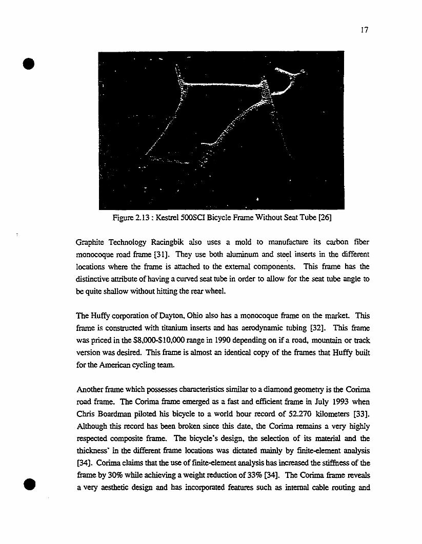
bikes [22]. Figure 2.13 shows the Kestrel 500SCI frame without a seat tube [26].
•
•
17
Figure 2.13 : Kestrel 500SCI Bicycle Frame Without Seat Tube [26]
Graphite Technology Racingbik also uses a mold to manufacture its carbon fiber
monocoque road frame [31]. They use both aluminum and steel inserts in the different
locations where the frame is attachc:d to the extemal components. This frame has the
distinctive attribute of having a curved seat tube in order to allow for the seat tube angle to
be quite shallow without hitting the rear wheel.
The Huffy corporation of Dayton, Ohio also has a monocoque frame on the market. This
frame is conslrUcted with titanium inserts and has aerodynarnic tubing [32]. This frame
was priced in the $8,000-$10,000 range in 1990 depending on if a road, mountain or !rack
version was desired. This frame is almost an identical copy of the frames that Huffy built
for the American cycling team.
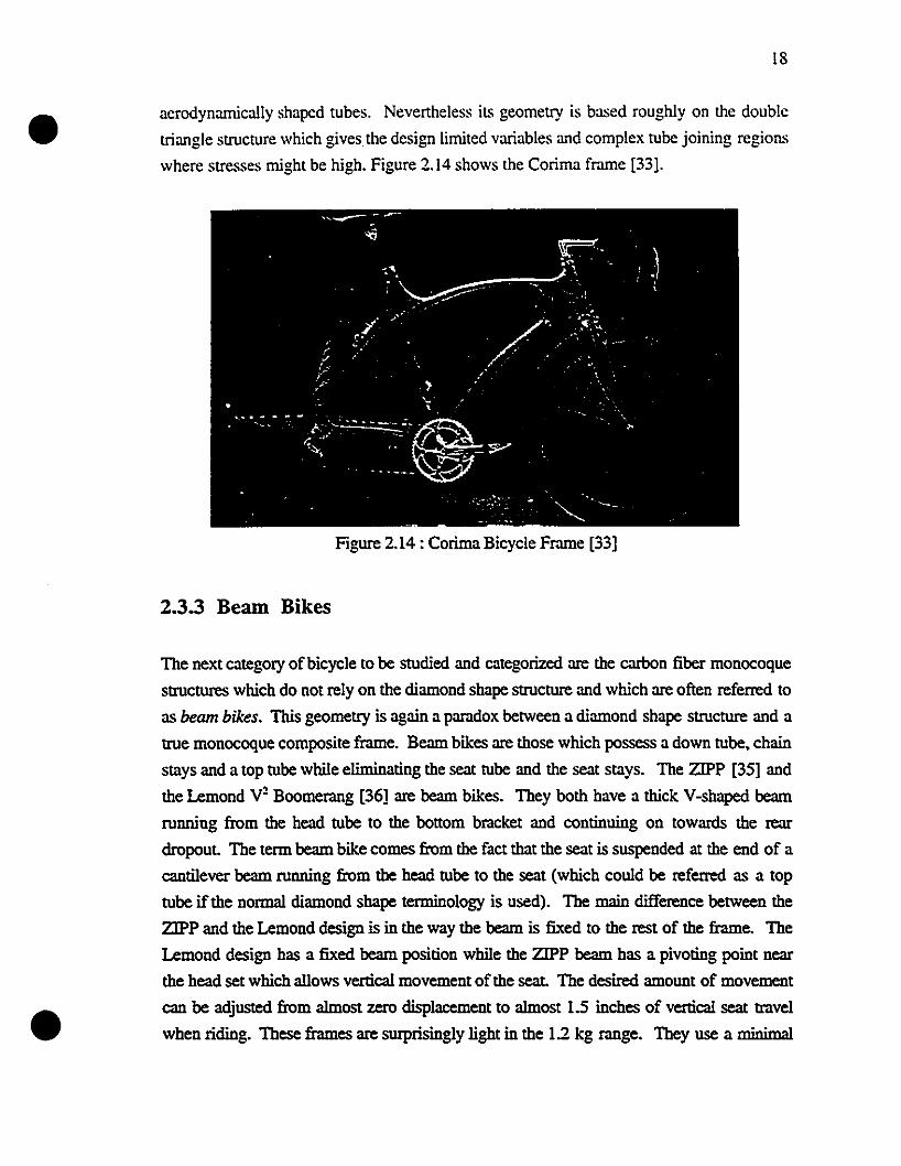
Another frame which possesses characteristics similar to a diarnond geometty is the Corima
road frame. The Corima frame emerged as a fast and efficient frame in July 1993 when
Chris Boardman piloted bis bicycle to a world hour record of 52.270 kilometers [33].
Although this record has been broken since this date, the Corima remains a very highly
respected composite frame. The bicycle's design, the selection of its material and the
thickness' in the different frame locations was dictated mainly by finite-element analysis
[34]. Corima claims that the use offmite-element analysis has increased the stiffness of the
frame by 30% while achieving a weight reduction of 33% [34]. The Corima frame reveals
a very aesthetic design and has incorporated features such as internai cable routing and
•
•
18
aerodynamically shaped tubes. Nevertheless il~ geometry is based roughly on the double
triangle structure which gives the design limited variables and complex tube joining regions
where stresses might be high. Figure 2.14 shows the Corima frame [33].
Figure 2.14 : Corima Bicycle Frame [33]
2.3.3 Bearn Bikes
The next category ofbicycle to be studied and categorized are the carbon tiber monocoque
structures which do not rely on the diamond shape structure and which are often referred to
as beam bikes. This geometry is again a paradox between a diamond shape structure and a
true monocoque composite frame. Bearn bikes are those which possess a down tube, chain
stays and a top tube while eliminating the seat tube and the scat stays. The ZIPP [35] and
the Lemond y2 Boomerang [36] are beam bikes. They both have a thick Y-shaped beam
running from the head tube to the bottom bracket and continuing on towards the rear
dropout. The term beam bike comes from the fact that the scat is suspended at the end of a
cantilever beam running from the head tube to the scat (which could be referred as a top
tube if the normal diamond shape terminology is used). The main difference between the
ZIPP and the Lemond design is in the way the beam is fixed to the rest of the frame. The
Lemond design has a fixed beam position while the ZIPP beam bas a pivoting point near
the head set which allows vertical movement of the scat. The desired amount of movement
can be adjusted from almost zero displacement to almost 1.5 inches of vertical seat trave!
when riding. These frames are surprisingly light in the 12 kg range. They use a minimal
•
•
19
amount of material as they only incorporate fr.une parts which are necessary to keep ail the
frame component~ together. The ZIPP has an adjusTable and even exchangeable beam
which adapts to riders of size r.mging l'rom I.60m to 1.93m. The advantage of this design
is that only one size of bicycle need be made and the actual size of the fr.une is adjusted for
each rider by changing only the beam. Unfortunately. these beam designs also have
disadvantages. As the beam acts as a cantilever structure and is unsupported at the seat
end, it allows for both vertical movement of the seat and lateral sway. The vertical
movement is relatively limited since the beam is deep with respect to its width, giving it
good rigidity in the vertical direction but not in the lateral one. This lateral sway has becn
noted as a problem in the riding of these bikes [35]. However, it seerns that the main
problem with this design is the actual geometry of the fr.une. The load transfer from the
rider's weight on the seat must be transferred in shear at the joint from the head tube to the
main down tube. The head tube region may already be higWy loaded by road forces and
moments induced by the riders arrns. so it seerns unwise that the introduction of the rider's
body weightto the rest of the frame be done al that location. The stand over height (height
of the frame at the front end of the seat) being quite high. these beam bikes are often
difficult to mount, even for experienced riders. Although they have interesting
characteristics, such as their excellent aerodynamics and low weight. the beam bikes have
had mixed success since their carly inception into the market Their limited popularity oùght
he linked to their non-conventional shape and relatively high priee. They have becn used
mostiy by triatWon riders. Figure 2.15 shows an example of the ZIPP bearn bike [37].
Figure 2.15 : ZIPP Bearn Bike [37]
•
•
20
2.3.4 True Monocoque Shapes
This last group of carbon liber fr.lmes arc among the most stale-of-the-an carbon liber
frames. They arc structures which truly depart From the tr.tditional diamond shape
structure.
The lirst f=e to be examined is Mike Burroughs Giant prototype [38]. lt includes sorne
of the basie components of the tr.tditional dian10nd geometry. but like the beam bikes \Vith
sorne parts omitted. This f=e has the sarne backbone as the beam bikes. going From the
head tube to the bottom br.lcket and then to the rear dropouts. H<>wever. instead of holding
the scat with a cantilever top tube. Burrough's decided to attach the seat to a seeuùngly
ordinary scat tube which extends to the bottom br.tcket. Hence this fr.tme docs not have
any top tube nor scat stays. This design is much more intuitively correct than the bcam
bike because the rider's weight is tr.Insferred to a bulky bottom br.lcket arca which forms
the core of the f=e. Also the load tr.Insfer is through a compression member (the scat
tube) instead of a cantilever beam as in the case of a beam bike. This prototype. which will
most likely bccome a production mode!. combines extreme rigidity with other Pr.lctical
concems such as a low stand-over height (a fcature which the beam bikes do not have),
I:ght weight and aesthetic design. It includes internai cable routing and a monoblade front
fork.
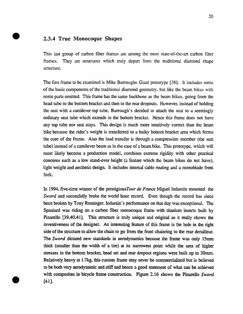
ln 1994, five-time winner of the prestigiousTour de France Miguel lndur.lin mounled the
SlVord and succesfully broke the world hour record. Even lhough the rt.'Cord has since
been broken by Tony Rouùnger.lndurain's performance on that day was exceptional. The
Spaniard was riding on a carbon fiber monocoque f=e with titanium inserts built by
Pinarello [39.40.41]. This structure is truly unique and original as it really shows the
inventiveness of the designer. An interesting fcature of this frame is the hole in the righl
side of the structure to ailow the chain to go from the front chainring to the rear derailleur.
The SlVord dictated new standards in aerodynamics bccause the frame was only 15mm
thick (srnaller than the width of a tire) at its narrowest point while the area of higher
stresses in the bonom bracket. head sct and rear dropout regions were built up to 30mm.
Relatively heavy at I.7kg. this custom frame may never be commercialized but is believed
to be both very aerodynanùc and stiff and hence a good statement of what cau be achieved
with composites in bicycle frame construction. Figure 2.16 shows the Pinarello Sword
[41].
•
•
21
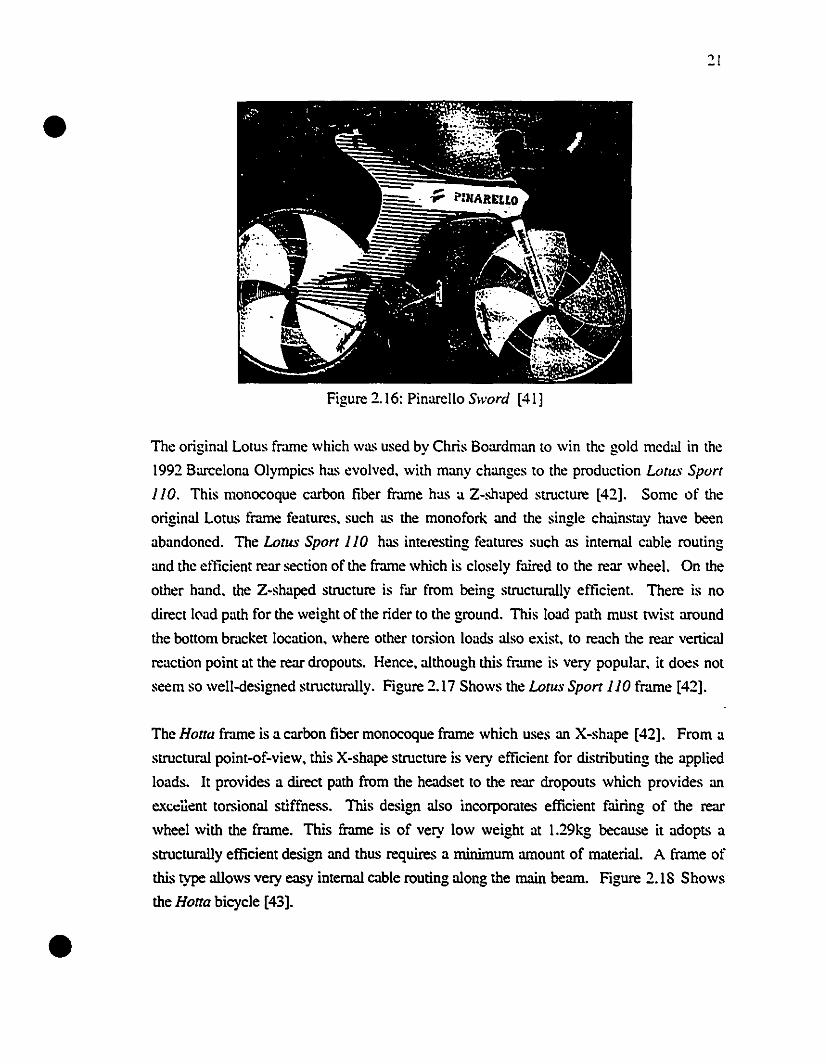
Figure 2.16: Pinarello Sword [41]
The original Lotus fr.une which was used bv Chris Boardman to win the gold medal in the- . -1992 Barcelona O1ympics has evolved. with many changes to the production Lotus Sport
110. This monocoque carbon fiber frame has a Z-shaped structure [42]. Sorne of the
original Lotus frame features. such as the monofork and the single chainstay have been
abandoned. The LotllS Sport 110 has interesting features such as internal cable routing
and the efticient rear section of the frame which is closely faired to the rear wheel. On the
other hand. the Z-shaped structure is far from being structurally efficient. There is no
direct l('ad path for the weight of the rider to the ground. This load path must twist around
the bonom br.lcket location. where other torsion loads also exist. to reach the rear vertical
reaction point at the rear dropouts. Hence. although this fr.une is very popular. it does not
seem so well-designed structurally. Figure 2.17 Shows the LotllS Sport 110 fr.une [42].
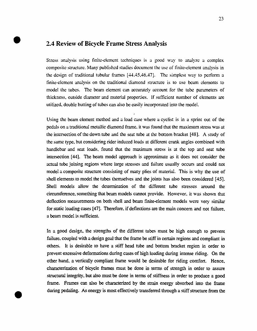
The Hotta frame is a carbon fiOer monocoque frame which uses an X-shape [42]. From a
structuml point-of-view. this X-shape structure is very efficient for distributing the applied
loads. It provides a direct path from the headset to the rear dropouts which provides an
excellent torsional stiffness. This design also incorporates efficient fairing of the rear
wheel with the frame. This frame is of very low weight at 1.29kg because it adopts a
structurally efficient design and thus requires a nùnimum amount of material. A frame of
this type alIows very easy internal cable routing along the main beam. Figure 2.18 Shows
the Hotta bicycle [43].
•
•
22
Figure 2.17: Lotus Sport 110 Frame [42]
Figure 2.18: Hotta Bicycle [43)
2.3.5 Summary of Current Carbon Fiber Frames
This review ofcarbon fiber frames on the market is far from being complete. but it helps to
understand why current diarnond shape frames or monocoque structures are used. It also
provides a framework for comparison with the prototypes which will be developed during
this project.
•
•
2.4 Review of Bicycle Frame Stress Analysis
Stress analysis using linite·c1ement techniques is a good way to analyze a complex
composite structure. Many published studies document the use of linite-c1ement analysis in
the design of tr.lditional tubular frames [44.45.46.47]. The simplest way to perform a
linite·c1ement analysis on the tmditional diamond structure is to use beam c1emenL~ to
mode! thc tubes. The beam e!cment can accur.ltcly account for the tube pammetcrs of
thickness. oUL~ide dimneter and matcrial proper.ies. If sufficient number of clements are
utilized. double butting of tubes can also be easily incorpor.ltcd into the mode!.
Using the beam c1emcnt method and a load case where a cyclist is in a sprint out of the
pedals on a tr.lditional mctallic diamond fr.une. it was found that the ma.ximum stress was at
the intcrsection of the down tube and the seat tube at thc bottom br.lcket [48]. A study of
the same type. but considering rider induced loads al different cr.lnk angles combincd with
handlebar and seat loads. found that thc maximum stress is at the top and seat tube
intersection [44]. The beam mode! approach is approximate as it does not consider the
actual tube joining regions where large stresses and failure usually occurs and could not
mode! a composite structure consisting of many plies of material. This is why the use of
shell elemenL~ to model the tubes themselves and the joinL~ has also been considered [45].
Shell models allow the detcrnùnation of the different tube stresses around the
cireumference. something that beam models cannot provide. However. it was shown that
deflection measuremenL~ on both shell and bearn finite-element models were very sirnilar
for static loading cases [47]. Therefore. if del1ections are the main concem and not failure.
a bearn model is sufficient.
In a good design. the strengths of the different tubes must be high enough to prevent
failure. coupied with a design goal that the f=e be stiff in certain regions and compliant in
others. It is desimble to have a stiff head tube and bollom bmcket region in order to
prevent excessive deformations during cases of high loading during intense riding. On the
other hand. a vertically compliant fr.une would be desimble for riding comfort. Hence.
characterization of bicycle frames must be done in terms of strength in order to assure
structural integrity. but also must be done in terms of stiffness in order to produce a good
f=e. F=es can also be characterized by the strain energy absorbed into the frame
during pedaling. As energy is most effectively transferred through a stiff structure from the
•
•
24
rider"s body to the baek whee!. a minimum of strain energy stored by the frame under
loading is desirable [46].
It is diffieult to eompare bicycle fmmes since each researcher and manufacturer utilizes a
different loading case or test method to chamcterize their frames. This is so because there
are very few standards for the detennination of performance of bicycle frames. The
existing standards are mostly for security and structuml integrity and cannot be used
directly to compare performance and rigidity of different fr.lmes. These standards offer
only statie and dynamic testing where one load is applied to one point whereas this is not
what happens in actual riding situations. Hence the standards are sometime only useful to
make sure that bicycles respect a certain baseline of structuml integrity but not as a design
tool for high performance r.lcing bicycles. However. new initiatives in bicycle standards
l'rom ISO [49]. JSA [50] and ASTM [51] will greatly contribute to the standardization of
test methods in the near future.
Since it is believed that high performance tmck and time trial composite bicycles should
evolve into the shape of monocoque tubeless frames. the lessons learned l'rom the tinite
element analysis of tubular fr.lI11es may not be relevant. This rese.lfch is thus aimed at using
tinite-element methods to perform stress analysis on monocoque composite fmmes r.lther
than on conventional tubular fmmes. Another study on monocoque composite material
frames has been performed but concenlr.ltes mainly on the construction process and testing.
and no tinite-element analysis was performed [52]. Also a study of a composite mountain
bike was performed but only considers finite-element static loading at one location to be
compared with the actual prototype. and docs not review the stresses during actual riding
conditions [53]. The use of a geometrically efficient structure combined with the desimble
properties of composites. a correct understanding of the loading and boundary conditions.
as weil as stress and failure analysis are ail important facLors for the development of a good
composite bieycle frame.
2.5 Review of Manufacturing Methods
Many methods can be employed to manufacture a composite structure. For the case of a
composite monocoque bicycle frame, more than one fabrication method exists. Each
method has its advantages and disadvantages. Hence. for a certain application, it is
important to know which method to use. This section will provide a quick non-exhaustive
•
•
ovcrvit:w of thc possihle fahrication mcthoùs for thc C(>nstruction (,fa composite hieycle
framc.
2.5.1 Wct La)'up
This methoù inn)l\"cs the application of ùry fahrie wetteù with an appropriate resin 0\"Cr a
previously shapcù foam core. The libers anù resin arc purchaseù separatdy. as opposeù to
preimpregnated materiaJ where the appropriate 4uantity of re,in is aJreaùy mixeù with the
libers. In the wet layup process. each layer of materiaJ is wetted with the resin and placed
on the structure. It is then allowed to room temper.lture cure. The main advantage of
buying the libers and resin separ.ltdy is (hat it is less expensive. Aiso it allu,,"s. up to a
certain extent. the choice of any libers to be used with any resin. There arc also many
disadvantages with this method. Although it is a rdiable process. it is by nature very slow
and labour intensive. Since no pressure is used during the curing process. the plies arc not
forced together in any way. This prevents the correct consolidation of the unbonded plies
into a bonded lanlinate. For this reason. this method is otien linùted to low-tech
applications where the interply bonding is not critical. Since this method uses an internai
open mouId. it will create a surface linish that may not be pcrfecl. Extensive sanding and
làiring will be required in order to obtain the proper surface quality. Aiso in order to assure
a good bonding between layers. it is otien required to sand in bet\Veen each layer again
increasing the labor lime. But the main disadvantage \Vith this method is the fact that it
otien results in heavy pieces as the volume fr.lction of liber and resin is difticult to control.
For structur.J.I consider.llions. it is better to have a resin rich structure than a resin delicient
one where it will be easier for cr.lcks to form and propagate. For this reason. more resin
than required is often added. resuIting in a heavicr structure.
2.5.2 Prepreg with Internai Bladder
This fabrication method involves a re-usable :2 or 3-part external mould. inside \Vhich an
internai bladder is used to create pressure on the preimpregnated material against the mould.
This fabrication method thus requires a re-usable mould made of alunùnum. epoxy.
liberglass or any other mould making material. The appropriate layup il' placed on the
mould with the preimpregnated material. After the layup is linished. a nylon/polyethylene
bladder is placed on one half of the mould. The mould is then c10sed and the bladder
inflated to a proper pressure. The mould is then placed in an oven for curing to take place.
•
•
26
This method produces an excellent surface finish because the extemal layer of the structure
is forced against the finished surface of the mould. This method has successfully been
used in the producùon of bicycle fr.unes for sorne Ùme now [54]. It is appropriate for
medium to large scale production. but not for small scale prototyping. It is thus an
expensive fabricaùon method for small quanùùes. but rapidly becomes worthwhile if many
pieces are to be produced. It provides a very light structure as it is internally filled with air
instead of the internai foarn used in sorne other methods. The thin nylon/polyethylene film
remains part of the structure after the curing has taken place. This method is quick and
clean. A frame can be produced in 2-3 hours with this method compared with 2-3 days
using the wet layup technique. This method cannot be completely automated, because it
sùll requires the hand layup of the composite prepreg in the mould. The internai bladder
technique is used in the construcùon ofbikes such as the Antelope [54]. the TREK OLCV
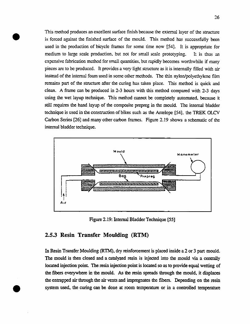
Carbon Series [26] and many other carbon frames. Figure 2.19 shows a schemaùc of the
internai bladder technique.
MoutdMQnom~teor
Figure 2.19: Internai BladderTechnique [55]
2.5.3 Resin Transfer Moulding (RTM)
In Resin Transfer Moulding (RTM), dry reinforcement is placed inside a 2 or 3 part mould.
The mould is then closed and a catalyzed resin is injected into the mould via a centrally
located injection point. The resin injection point is located so as to provide equal wetting of
the fibers everywhere in the mould. As the resin spreads through the mould, it displaces
the entrapped air through the air vents and impregnates the fibers. Depending on the resin
system used. the curing cao be done at room temperature or in a controlled temperature
•27
oyen. Similar to the internai bladder method. this construction technique uses an external
mould which may be improper for a small production. However it provides a very good
surface finish. In order to produce a bicycle frame with this method. it might be necessary
to use an internai foam core in the mould in order to provide the required wall thickness.
But for the making of a very thin bicycle frame such as the ones often used in ùme trials.
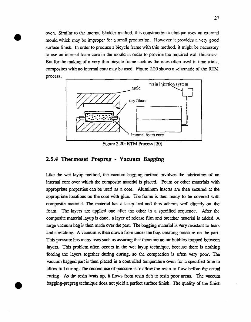
composites with no internai core may be used. Figure 2.20 shows a schematic of the R1M
process.
c--- .
dry libers
internai foam core
resin injectio~
irli1--------\ i
=.
mold""-"""",,,,"""""-7'--:::;
tp'lL/(j
Figure 2.20: RTM Process [20]
2.5.4 Thermoset Prepreg - Vacuum Bagging
•
Like the wet layup method. the vacuum bagging method involves the fabricaùon of an
internai core over which the composite rnaterial is placed. Foam or other materials with
appropriate properùes can be used as a core. A1uminum inserts are then secured at the
appropriate locaùons on the core with glue. The frame is then ready to be covered with
composite material. The rnaterial has a tad.")' feel and thus adheres weil directly on the
foam. The layers are applied one after the other in a specified sequence. After the
composite materiallayup is done. a layer of release film and breather material is added. A
large vacuum bag is then made over the part The bagging material is very resistant to tcars
and stretching. A vacuum is then drawn from under the bag. creating pressure on the part.
This pressure has many uses such as assuring that there are no air bubbles trapped between
layers. This problem often occurs in the wet layup technique. because there is nothing
forcing the layers together during curing. so the compacùon is often very poor. The
vacuum bagged part is then placed in a controlled temperalure oyen for a specified Ùffie to
allow full curing. The second use of pressure is to allow the resin to flow before the aetuaI
curing. As the resin heats up. it flows from resin rich to resin poor areas. The vaccum
bagging-prepreg technique does not yield a perfect surface finish. The quality of the finish
•
•
28
is very much dependcn! on the quality of the vacuum bag. Often sanding is required after
the curing in order to remove resin wrinkles. A primer and pain! can then be applied so as
to improve the surface finish.
2.5.4 Thermoplastic
Instead of using a thermosetting composite. it is possible to use a thermoplastic material.
The thermoplastic matrix (PEEK. PPS. Polysulfone. Polyimide. etc.) can be used with
almost ail of the conventional fibers in order to make a prepreg. This prepreg is dry and
can he kept at room temperature. The method of using the thermoplastic prepreg is the
same as the thermoset prepregs and thus could be used in the internai bladder or vaccum
bagging method. Thermoplastic prepregs are not as weIl known as the conventionnai
thermosets as they are newer and have not been used in as many applications. They are
often used in high-tech applications were fracture toughness is important. This property is
very important for bicycle frames. hence they could be used in the near future. The
problem with thermoplastics is that they are not tacky at room temperature and hence it may
he difficult to construct a layup of many superimposed layers on an intricate shape.
•
•
29
Chapter 3
Traditional Frames
3.1 Rationale for Modeling and Testing Traditional Frames
Although this research concentrates on composite frames. it is important to understand how
and why traditional frames should be improved upon. Thus. as part of this research, a
summary investigation of traditional metallic bicycle frames was performed. Some
traditional frames were modeled using finite element analysis (FEA) and then tested using a
specially built testing jig in order to quantify their stiffness in different directions and to
correlate results with the FEA models. The results also provide baseline values for frame
stiffness. so that valid conclusions can be made for the new composite structures. This
preliminary static testing of traditional frames also permiued to establish the experimental
procedure required for the static testing of the composite frames.
3.2 Finite Element Analysis of Traditional Frames
The finite element analysis of traditional frames was performed in order to quantify the
stiffness of these frames, and also to show that correlation between the finite element
results and the testing jig could be obtained. The finite element analysis was performed
using SRDC'S l-OEAS software [56] at McGill University. This fmite element software
combines good 3-0 graphies, element library and pre- and post-processing.
In order to model traditional bicycle frames, two approaches were utilized. The fIrSI one
considered each tube of the frame as a beam element, thus creating a beam frame structure.
The inside and outside diameters of the beams were cross-section material properties of the
beam elements. Thus the beam elements could be defined by thcir end-point locations in 3-
•
•
30
D space. This procedure is simple but. as will be seen later. does not yield ail the
necessary results. A typical fr.une modeled using this technique may contain only 10
elemenL~ and be readily solved requiring minimal computer time. The other approach is to
model the whole frame using ~hell clements. This procedure models each tube with
rectangular and triangular thm s;.1ell elements. The tubes may contain 6-8 such elements
around their circumferences. and an appropriate amount along their length resulting in
models with over 1000 shell elements and thus requiring more extensive computer lime.
The geometry of the junction between the tubes is achieved manually by creating triangular
or rectangular thin shen elements connecting thc intersecting tubes. It is obviously much
simpler to model a frame using beam elements but a better analysis is donc by
understanding the tube intersection stress analysis. Depending on the results required
(stiffness or strength) an appropriate choice of modeling techniquc can be chosen. The
modeling of a frame using beam elements can yield fairly accurate displacements and thus
stiffness parameters. However. it is difficult to obtain an accurate account of the stress
levels and patterns associated with the structure. On the other hand. if wc use thin shen
elements. in addition to accurate displacement results. the longitudinal and circumfcrential
stresses present in the tubes can also be obtained. Hence if a stiffness-only study is
required. beam elements modeling the frame might be sufficient for certain stiffness
measurements. On the other hand. if a complete stiffness and strength study is required.
thin shen finite elements should be used to model a traditional tubular frame.
3.3 Experimental description
In order to effectively compare different frames. a series of static tests were developed.
Each test corresponds to a different loading case where forces are applied to different parts
of the frames and where other parts of the frames are restrained. The different static tests
are shown in Figure 3.1.
The individual tests are aimed at measuring a different char.lcteristic that may or may not be
beneficial to the rider and thus characterizes a good or a bad frame. A description of each
test from figure 3.1 will give a preliminary qualitative explanation of what kind of result is
desirable.
•31
"lltU-of-p!;II1l.:((lad" 6IXJ;-.I
10001'1
Test 1
(a)
Test 2
(b)
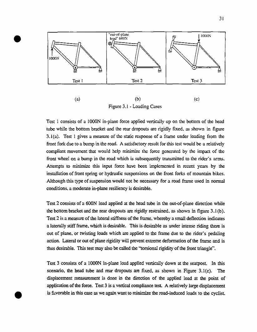
Figure 3.1 - Loading Cases
Test 3
(c)
•
Test 1 consists of a IOOON in-plane force applied vertically up on the bottom of the head
tube while the bottom bracket and the rcar dropouts are rigidly fixed. as shown in figure
3.I(a). Test 1 gives a measure of the static response of a frame under loading from the
front fork due to a bump in the road. A satisfactory result for this test wouId be a relatively
compliant movement that wouId help minimize the force genemted by the impact of the
front wheel on a bump in the road which is subsequently tr.tnsmitted to the rider's arms.
Attempts to minimize this input foree have been implemented in recent years by the
installation of front spring or hydr.tulic suspensions on the front forks of mountain bikes.
Although this type of suspension would not be necessary for a road frame used in nonnal
conditions. a moderate in-plane resiliency is desirable.
Test 2 consists of a 600N load applied at the head tube in the out-of-plane direction while
the bottom bracket and the rear dropouts are rigidly restrained. as shown in figure 3.1 (b).
Test 2 is a measure of the lateral stiffness of the frame. whereby a small deflection indicates
a later.tlly stiff frame. which is desirable. This is desirable as under intense riding there is
out of plane. or twisting loads which are applied to the frame due to the rider's pedaling
action. Lateral or out of plane rigidity will prevent extreme defonnation of the frame and is
thus desirable. This test may a1so be called the "torsional rigidity of the front triangle".
Test 3 consists of a lOOON in-plane load applied vertically down at the seatpost. In this
scenario. the head tube and rear dropouts are fixed. as shown in Figure 3.I(c). The
displacement measurement is done in the direction of the applied load at the point of
application of the force. Test 3 is a vertical compliance test. A relatively large displacement
is favorable in this case as we again want to minimize the road-induced loads to the cyclist.
•
•
In a modilied triangular diamond shape structure. a way to appease the rider from a surface
bump could be to build a fmme like the Kestrel 500SCI (sec ligure 2.13) which climinates
the scat tube and thus would result in a more vertically compliant structure. Aiso. many
touring bicycle fmmes have scat mounted springs for the same reasons.
Since ail the tests are performed within the clastic limit of the material. the choice of load to
be applied is arbitr.ll)' as the load-displaeement curve is linear in the e1:l~tic region. The
above loads were chosen in order to obtain measurJ.ble dellections for the appropriate tests.
This series of tests is a satisfactory but non-exhaustive list that may be modilied or updated
in order to provide for a more complex and complete analysis in the future.
3.4 Experimental and Theoretical Techniques for Traditional
Frames
The 3 tests described in section 3.3 were simulated on 3 different models using FEA in
order to obtain stiffness values for tmditional geometry frJ.mes. The 3 models consisted of
one classical diarnond shape frJ.me that was modcled using isotropic shell clements. and
two classical frames modeIed using beam elements. A 52 cm chromium-molybdenum steel
frame built using Reynolds 501 tubing was modeled using isotropic shell elemenl~ and also
using bearn clements. Also. a 58 cm Trek 1100 frame made of 6061 aluminum tubing was
modeled using bearn elements only.
The experimental measurements on both the steel and aluminum frJ.mes were performed on
a specially built testingjig developed at McGill University. The jig consists of a rigid box
structure made of rectangular members with a large cross sectional area in order to restrict
the jig to minimal defleetions comparcd to those of the bicycle frame. Different points of a
bicycle frame can be ftXed to the structure using attachmenl~. thus creating fixed boundary
conditions for the test. Hydraulic cylinders were attached to the testingjig in order to apply
loads to the bicycle frame. By varying the placement of these hydraulic cylinders. load can
be applied in any axis. and at aImost any point on the bicycle frame. The applied load is
measured by calibrated load cells placed between the hydraulic cylinders and the load
application points on the frame. The displacements at the different locations arc measured
using dial gages. Figure 3.2 shows the testing jig used to test the frames.
(3.1 )
•
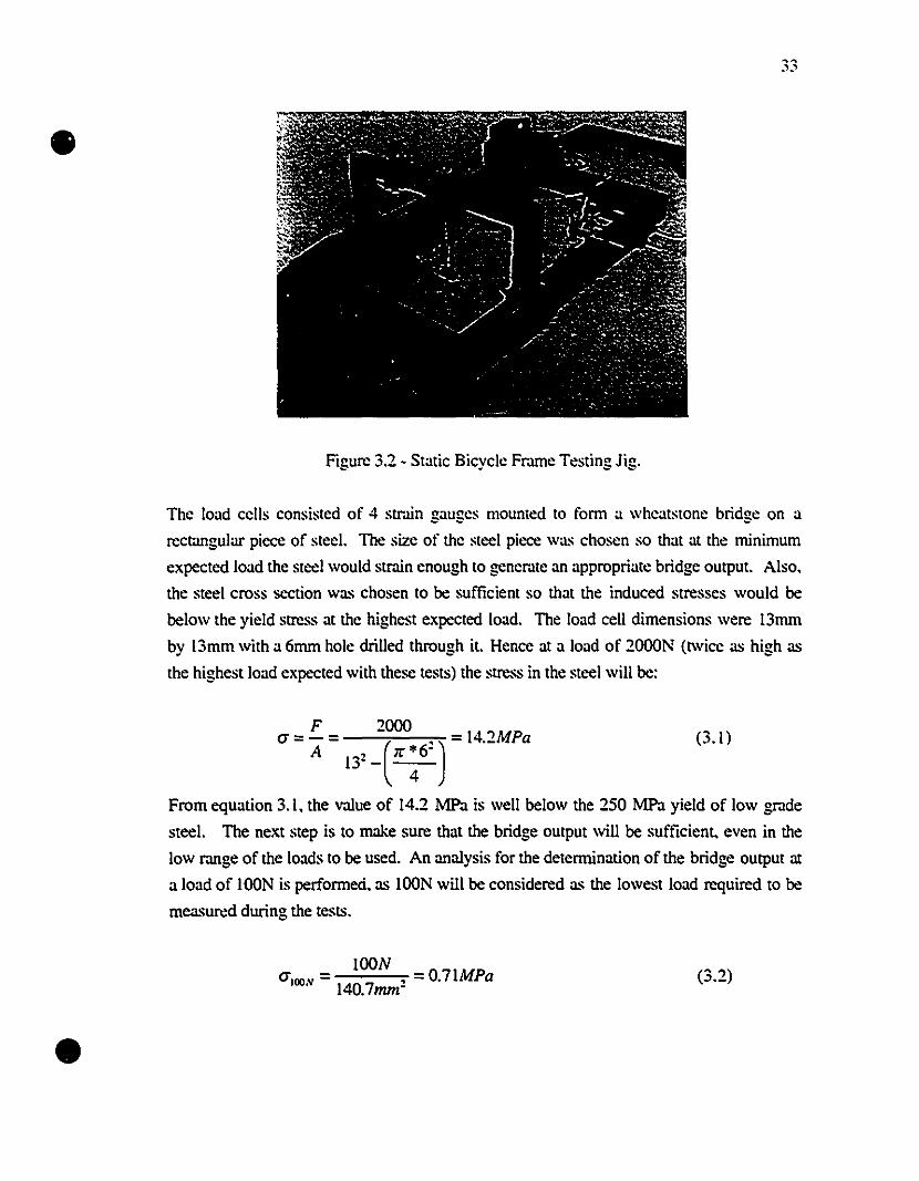
Figure 3.2 - StatÎC Bicycle FrJ.lTle Testing Jig.
The load cells consisted of 4 strJ.in gauges mounted to fonn a wheatstone bridge on a
rectangular picce of steel. The size of the steel picce was chosen so that at the minimum
expected load the steel would strain cnough to generate an appropriate bridge output. Also,
the steel cross section was chosen to be sufficient so that the induced stresses would be
below the yield stress at the highest expected load. The load cell dimensions were 13mm
by 13mm with a 6mm hole drilled through it. Hence at a load of 2000N (l\vice as high as
the highest load expccted with these tests) the stress in the steel will he:
F 2000Ci =- = ( ') 14.2MPaA 132 _ ;r :6'
From equation 3.1, the value of 14.2 MPa is well below the 250 MPa yield of low grade
steel. The next step is to make sure that the bridge output will be sufficient, even in the
low rJ.nge of the loads to be used. An analysis for the determination of the bridge output al
a 10ad of l00N is perfonned, as l00N will be considered as the lowest 10ad required to be
measured during the tests.
•l00N
CiIlJON = , = 0.71MPa140.7mm"
(3.2)
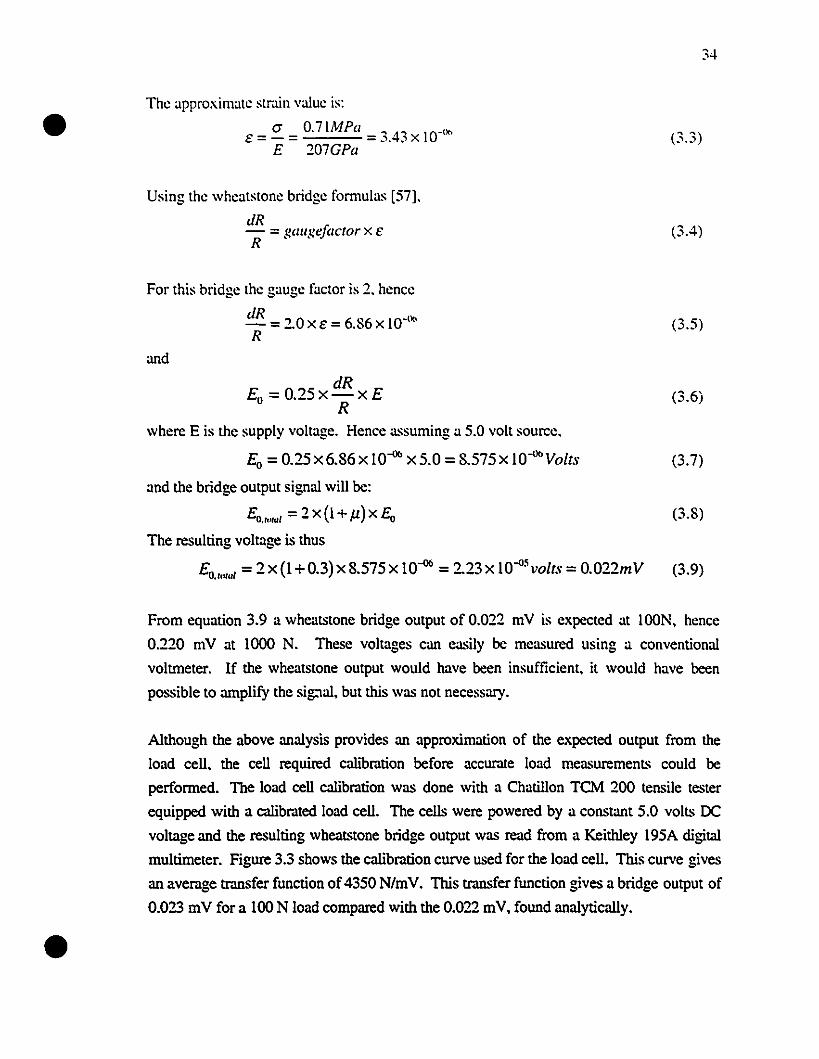
• The approximate str.lÏn value is:
(j 0.71MPaE=-= 3.43 X 10-'1<>
E 207GPa
Using the wheatstone bridge fomlUlas [57].
dR- = ~all~el(/("tor x ER • • J'
For this bridge the gauge factor is 2. hencc
dR _ ") a = 6 86 10-°"-_. XE • XR
and
34
(3.3)
(3.4)
(3.5)
(3.6)
•
where E is the supply voltage. Hence assuming a 5.0 volt source.
Eo =0.25x6.S6x lO-Il<> x5.0 =S.575 x lO-Il<>Yolts (3.7)
and the bridge output signal will be:
ED.".I = 2 x (1 +Jl) x ED (3.8)
The resulting voltage is thus
ED.",w' = 2 x (1 +0.3) x S.575 x 10-ll<> = 2.23 x 10-05 volts = 0.022mY (3.9)
From equation 3.9 a wheatstone bridge output of 0.022 mV is expected at lOON, hence
0.220 mV at 1000 N. These voltages can easily be measured using a conventional
voltmeter. If the wheatstone output would have been insufficient. it would have been
possible to amplify the sig:tal, but this was not necessary.
Although the above analysis provides an approximation of the expected output from the
load cell, the cell required calibration before accurate load measuremenL~ could be
performed. The load œil calibration was done with a Chatillon TCM 200 tensile tester
equipped with a calibrated load cell. The cells were powered by a constant 5.0 volts OC
voltage and the resulting wheatstone bridge output was read from a Keithley 195A digital
multimeter. Figure 3.3 shows the calibration curve used for the load cell. This curve gives
an average traDsfer function of4350 N/mV. This transfer function gives a bridge output of
0.023 mV for a 100 N load compared with the 0.022 mV, found analytically.
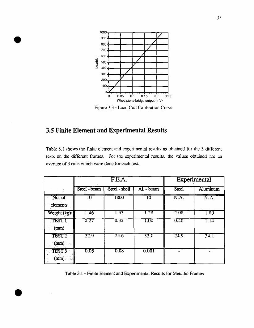
//
/
/V
//
//
300
200
100
oo 0.05 0.1 O., 5 0.2 0.25
Wheatstone bridge output (mV)
Figure 33 - LlKld CclI Calibration Curve
1000
900
800
700
600z-g 500
.3 400
•
3.5 Finite Element and Experimental Results
Table 3.1 shows the tinite clement and expcrimental results as obtained for the 3 ditTerent
tests on the different fmmes. For the experimental results. the values obtained 'U'C an
avemge of 3 runs which were donc for eaeh test.
F.EA. Experimental
. Steel-beam Steel- shell Al.-beam Steel Aluminum1·
No. of 10 ISOO 10 NA N.A.
cléments
Weight(kg) 1.46 1.53 1.2S 2.0S I.S0. C •
TEST! 0.27 0.32 1.00 0.40 1.14
(mm)
TEST 2 22.9 25.6 32.0 24.9 34.1
. (mm).. .T~T3·· . 0.05 O.OS 0.001 - -
.. (mm) ..•.
•Table 3.1 - Finite Element and Experimental Resull~ for Metallic Fr.unes
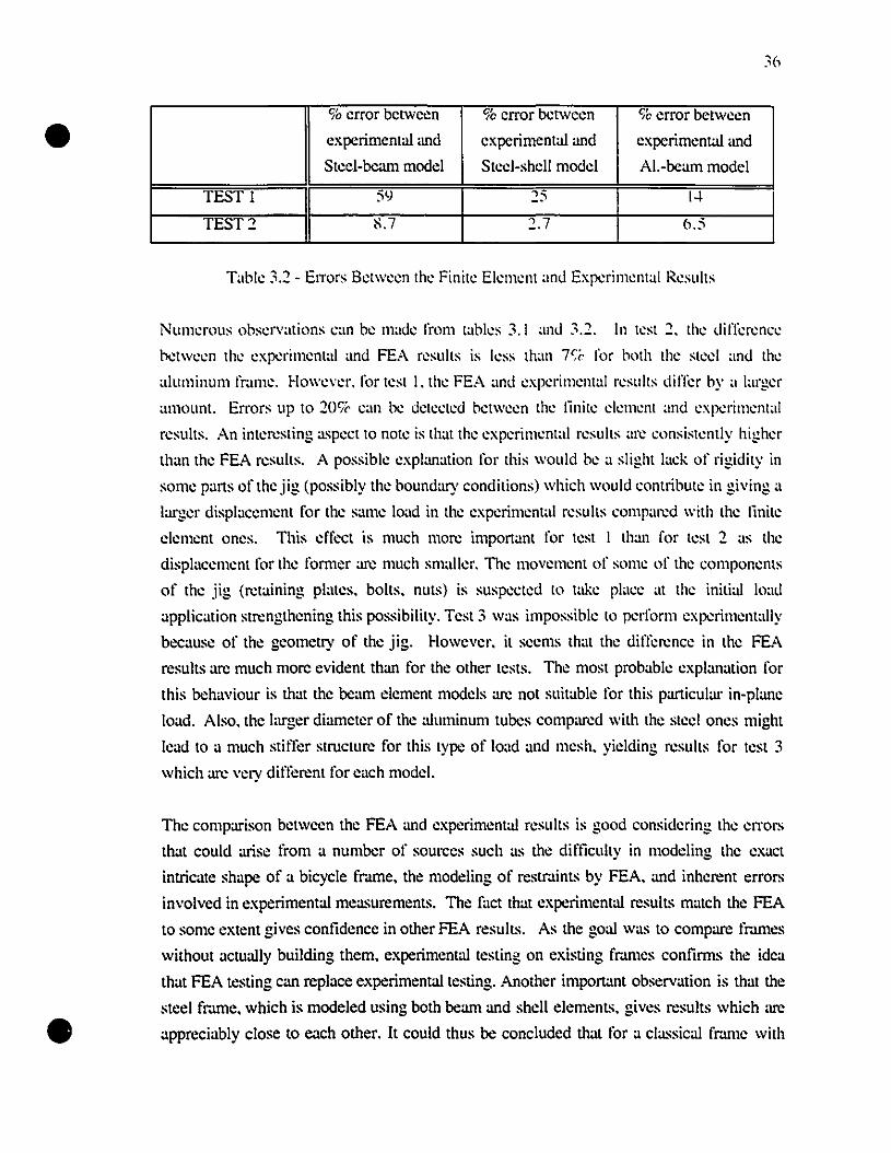
•
•
% error between 9é crror bctwccn CJé crror bctwccn
experimental and experimental and experimental and
Steel-bcam modcl Steel-shel! model A!.-beam model
TEST 1 S\l 25 1-1
TEST::! 'i>.7 :'.7 6.5
Tabh: 3.:' - EITors Between the Finite Element and Experimental Results
Numerous observations ean be made from tables 3.1 and 3.:'. In test :.. the difrcrenee
between the expcrimental and FEA results is less than 7% for hoth the stecl and the
alumil1lll11 frame. However. for test 1. the FEA :md experimelllai results dilTer by a larger
amounl. En'ors up to :'Oç~ ean be detecled hetween the linile c1emenl and expcrimelllai
results. An interesting aspect to note is lhat the experimental results :U"C consistentlv higher~ . -
than the FEA results. A possible explanation for this would be a slight Iack of rigidity in
some parts of the jig (possibly the boundary conditions) which would contribule in giving a
larger displaccment for the same load in the experiment:ll results compared with the linite
clement ones. This effect is mueh more important for test 1 than for test ::! as the
displ:\eement for the former are much snml!er. The movement of some of the eomponems
of the jig (retaining plates. bolts. nuts) is suspected lo t:lkc pl:lce at the initial load
application strengthening this possibility. Test 3 was impossible lo perfonll expcrimentally
because of the geometry of the jig. However. it secms that the dilTerence in lhe FEA
results = much more evident than for the other tests. The most probable explanation for
this behaviour is that the beam clement models are not suitable for this particular in-plane
load. Aiso. the larger diameter of the a1uminum tubes comp=d with the sleel ones might
lead 10 a much stiffer structure for this type of 10:ld and mesh. yielding results for test 3
which arc very different for each mode!.
The comparison between the FEA and experimemal results is good considering the errors
that could arise l'rom a number of sources such as the difticulty in modeling the exact
intricate shape of a bicycle fr.une, the modeling of restmints by FEA, and inherent errors
involved in experimental mea.~uremenl~. The fact that experimental resull~ match the FEA
to some extent gives confidence in other FEA results. As the goal was to comp= fr.unes
without actually building them, experimental testing on existing fmmes confimls the idea
that FEA testing can replace experimental testing. Another important observation is that the
steel fr..lme, which is modeled using both beanl and shel! clements. gives results which =
appreciably close to each other. It could thus be concluded that for a classical fr.une with
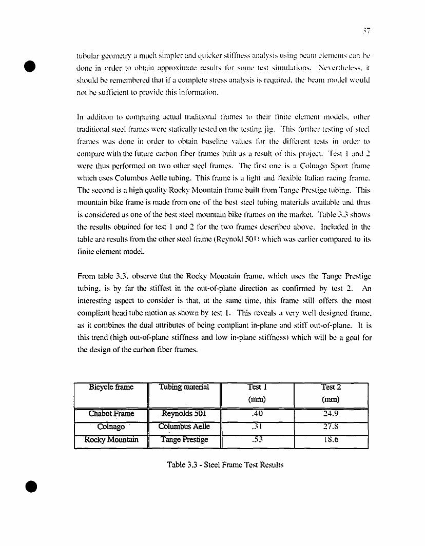
•
•
37
tlInular g.:om':lry;' mu.:h simpkr and qui-:k.:r sliffn.:ss analysis using k;II11l'1.:m"nts "an nl'
don.: in ord.:r 10 ontain approximaI': r.:sults for som.: l.:sl simulations. '\':\l·l1hd"ss. il
should n.: r.:m.:mn.:r.:d lhal if;1 .:ompkl': Slr.:ss analysis is r.:quir.:d. lh.: n"am I110dd \\'llUld
nol n.: suflki.:nt to pro\'id.: lhis informaI ion.
ln addilion 10 çomparing a.:lual tradilional f!"am.:s to Ih.:ir Iinil.: d.:m.:nt mod.:1s. olh.:r
Iradition~li sl.:d fram.:s \\'.:r.: st;lli.:ally l<:st.:d on lh.: I.:sling jig. This fUl1h.:r l<:sling of sl.:d
fr;un.:s \\'as don.: in ord.:r to ontain basdin.: \'alu.:s for lh.: difll:r.:nl l.:sts in ord.:r to
çompare \\'ilh the futur.: çarnon liner fr.unes buill as a r.:sull of lhis proj.:.:!. T.:sI 1 and 2
\\'.:r.: lhus p.:rllmn.:d on t\\'o olher sl.:d fram.:s. Th.: lirsl on.: is a Colnago Sport fram.:
which uses Columnus Aelle lubing. This frame is a light ~md Ilcxible Ilalian radng fram.:.
The second is a high quality Rocky ivllllll1tain frame buill l'rom T.mge Prestige tubing. This
mountain bike frame is made l'rom one of the besl slcd tlIbing malerials a\'.ül~lble .lI1d Ihus
is considered as one of the best slecl mOlll1lain bike fr.lmes on the mark.:!. Tabk 3.3 shows
the results obwined for tesl 1 and 2 Il)r the two fram.:s describco abo\'e. Induded in the
lable arc resulls l'rom lhe other sted frame (Reynold 50 t ) which was .:arlier comp;lred to its
Iïnite cl.:menl modcL
From table 3.3. obser\'e that the Rocky MOU:llain frame. which uses Ihe Tang.e Prestig.e
tubing. is by far the stiffest in the mlt-of-plane direction as conlïmled by test 2. An
interesting aspect to consider is th'lt. at the :;;lme time. this Ihlme still offers the most
compli'lOl head tube motion .LS shown by lest 1. This re\'eals a \'ery weil designed frame.
as il combines lhe du'll attributes of being compli'lOl in-pl.me and stitT out-of-plane. It is
this trend Chigh olll-ol~plane sliffness and low in-plane stilTness) which will be .1 goal for
the design of the c'lrbon tïber frames.
Bicycle frame Tubing material Test l Test 2
(mm) (mm)
Chabot Frame Reynolds 501 .40 24.9
Colnago Columbus Aelle .31 27.8
Rocky Mountain Tange Prestige .53 18.6
Table 3.3 - Steel Fmme Test ResuIls

•
•
38
ln chapter -1 these results will bc compared with the composite prototypes whieh will bc
constructed. Even though these traditional frames are nN the best racing frames on the
market. they are of reasonable quality so as to provide an adequate bascline upon which the
composite frames should be improved upon.
•
•
39
Chapter 4
Composite Frame Design
4.1 Introduction
This chapter will focus on the design and finite-element analysis of the composite frames
developed during this project. This is the core of the research. ln order to set goals for this
study. a number of design criteria were set forward. The first criteria is low weight. A
fmme weight on the order of t500g should be sought. This is slightly tower than other
composite frames on the market and in the sarne range as the lightest alurninum frames
available. The second design criteria is to obtain a frame with the appropriate stiffness at
the appropriate locations. The head tube and bonom bmcket stiffnesses should be as high
as the stiffest f=es on the market (such as the ones sarnpled in chapter 3). The frame
should also be compliant in the vertical direction in order to help dissipate road
irregularities. These criteria will guide the design and construction of the composite
monocoque f=es.
4.2 Finite-Element Analysis of the Composite Frames
The finite-element analysis of the monocoque bicycle f=es was performed using SDRe's
l-DEAS fmite-element software [58]. This software is particularly appropriate for this type
of structure as il incorporates both a very good composite larninate modeling section with
advanced geometric modeling capabilities. l-DEAS uses a standard classical larninated
plate theory with an option to calculate additional interlaminar shear stresses. The laminate
modeling section directly computes ail of the stiffness matrice.~ which are inherent to the
use of materials with orthotropic material properties (i.e.. composite materials). The
calculations and manipulations of the stiffness matrices for each larninate are very tedious.
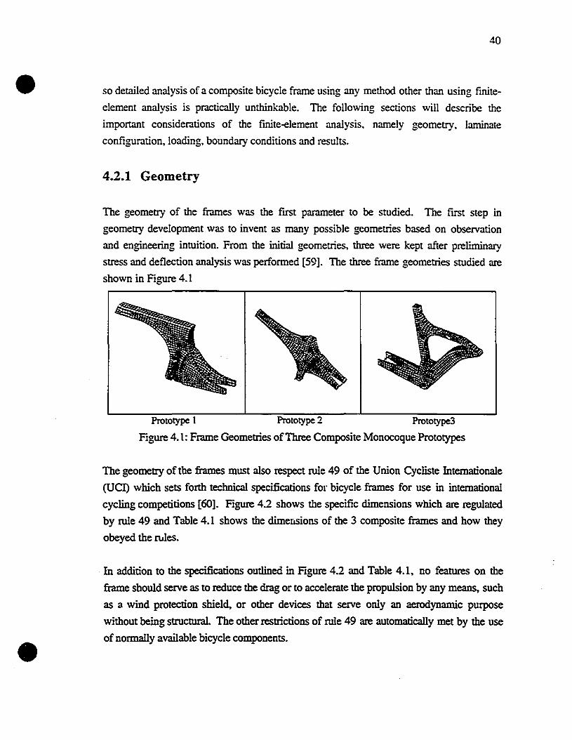
•40
so detailed analysis of a composite bicycle frame using any method other than using finite
element analysis is practically unthinkable. The following sections will describe the
important considerations of the finite-element analysis. namely geometry. laminate
configuration. loading. boundary conditions and results.
4.2.1 Geometry
The geometry of the frames was the fmt parameter to be studied. The fmt step in
geometry development was to invent as many possible geometries based on observation
and engineering intuition. From the initial geometries, three were kept after prelirninary
stress and deflection analysis was performed [59]. The three frame geometries studied are
shown in Figure 4.1
•
Prototype 1 Prototype 2 Prototype3
Figure 4.1: Frame Geometries ofThree Composite Monocoque Prototypes
The geometry of the frames must also respect rule 49 of the Union Cycliste Internationale
(UCl) which sets forth technieal specifications for bicycle frames for use in intemational
cycling competitions [60]. Figure 4.2 shows the specific dimensions which are regulated
by rule 49 and Table 4.1 shows the dimet:lsions of the 3 composite frames and how they
obeyed the rues.
In addition to the specifications outlined in Figure 4.2 and Table 4.1, no features on the
frame should serve as to reduce the drag or to accelerate the propulsion by any means, such
as li wind protection shield. or other devices that serve only an aerodynamic purpose
without being structural. The other restrictions of rule 49 are automatically met by the use
of normally available bicycle components.
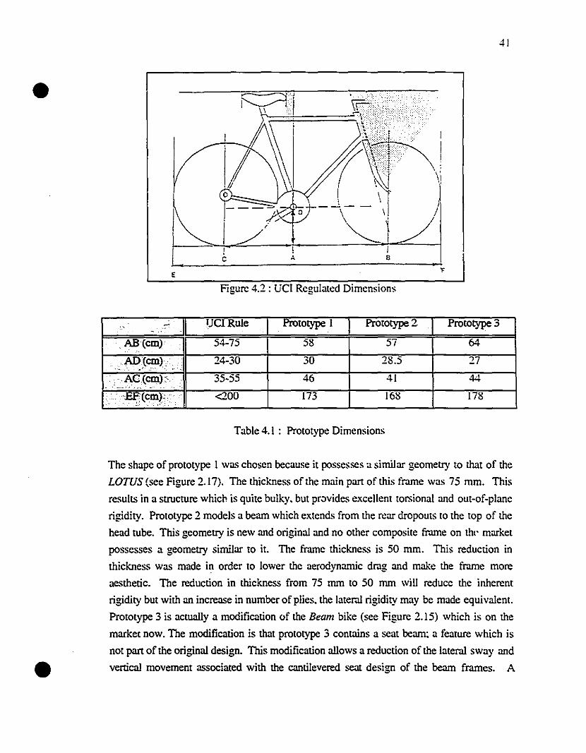
41
18
1A
F:::::::;::1==::::::"~:?i··
1 r~\i1 ~ •, \
_~__ 1
~\ /
1c
•
E
Figure 4.2 : UCI Rcgulated Dimensions
., .. IJCI Rule Prototype 1 Prototype 2 Prototype 3.. AB (cm) 54-75 58 57 64
AD(cm) .. 24-30 30 28.5 27"
,~.> ' " .. .::~5(cm):' 35·55 46 41 44
cEF'(cm).. ····· <200 173 168 178k ~: ",' ~:: . ,;~,": '
Table 4.1 : Prototype Dimensions
•
The shape of prototype 1 was chosen because it possesses a similar geometry to that of the
LOTUS (see Figure 2.17). The thickness of the main part of this frame was 75 mm. This
results in a structure which is quite bulky. but pr~vides excellent torsional and out-of-plane
rigidity. Prototype 2 models a beam which extends from the rear dropouts to the top of the
head tube. This geometry is new and original and no other composite fr.une on th(' market
possesses a geometry similar to il. The frame thickness is 50 mm. This reduction in
thickness was made in order to Iower the aerodynamic drag and make the frame more
aesthetic. The reduction in thickness from 75 mm to 50 mm will reducc the inherent
rigidity but with an increase in number of plies. the lateral rigidity may be made equivalenl.
Prototype 3 is actually a modification of the Bearn bike (see Figure 2.15) which is on the
market now. The modification is that prototype 3 contains a seat beam; a feature which is
not part of the original design. This modification aIIows a reduction of the lateral sway and
vertical movement associated with the cantilevered scat design of the beam frames. A
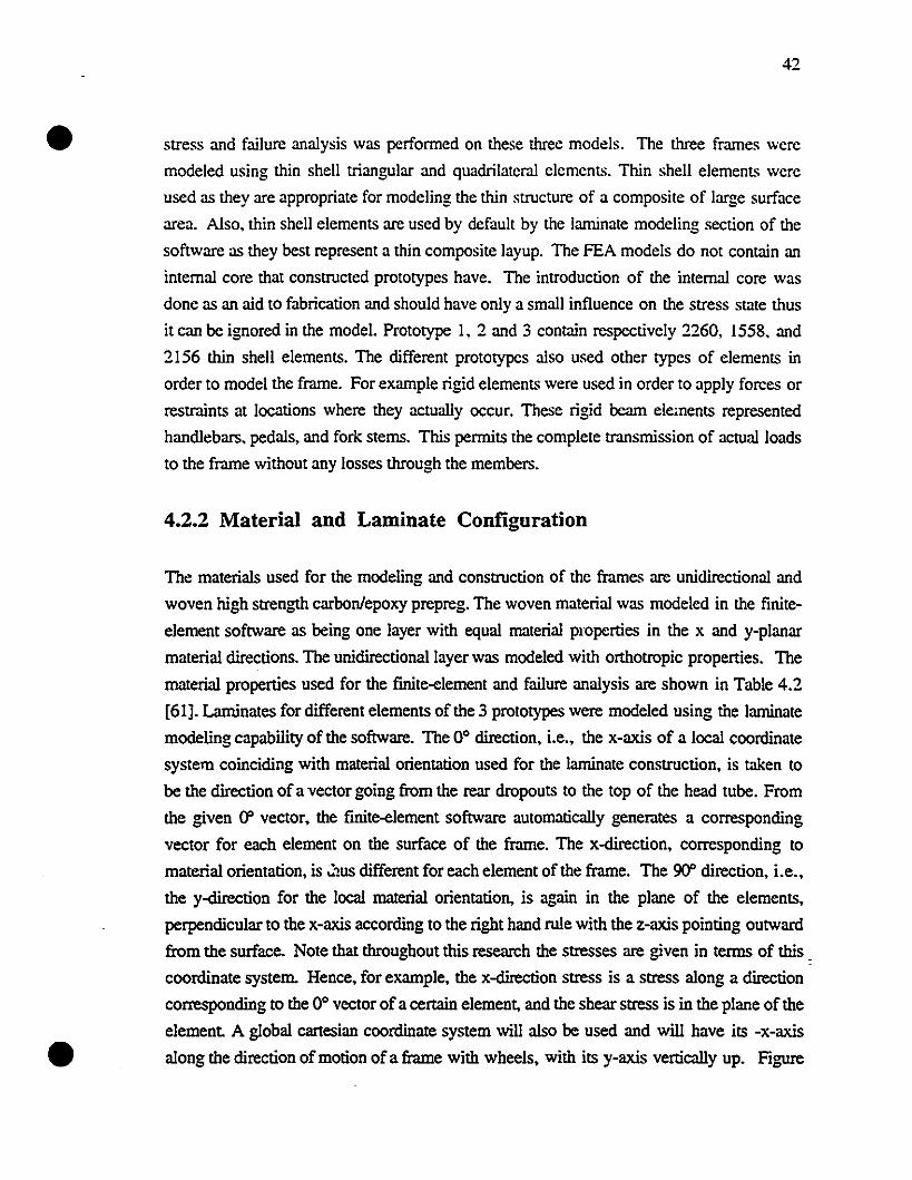
•
•
42
stress and failure analysis was perforrned on these three models. The three frames were
modeled using thin shell triangular and quadrilateral clements. Thin shell elemenL~ were
used as they arc appropriate for modeling the thin structure of a composite of large surface
area. Also, thin shell elements are used by default by the laminate modeling section of the
software as they best represent a thin composite layup. The FEA models do not contain an
internai core that eonstrueted prototypes have. The introduction of the internai core was
donc as an aid to fabrication and should have only a small influence on the stress state thus
it can be ignored in the mode!. Prototype 1, 2 and 3 contain respectively 2260, 1558, and
2156 thin shell elements. The different prototypes also used other types of elements in
order to model the frame. For example rigid elements were used in order to apply forces or
restraints at locations where they actually occur. These rigid beam elements represented
handlebars, pedals, and fork stems. This perrnits the complete transmission of actual loads
to the frame without any losses through the members.
4.2.2 Material and Laminate Configuration
The materials used for the modeling and construction of the frames are unidirectional and
woven high strength carbonlepoxy prepreg. The woven material was modeled in the finite
element software as being one layer with equal rnaterial properties in the x and y-planar
material directions. The unidirectionallayer was modeled with orthotropic properties. The
material properties used for the fmite-element and failure analysis are shown in Table 4.2
[61]. Laminates for different elements of the 3 prototypes were modeled using the laminate
modeling capability of the software. The 0° direction, i.e., the x-axis of a local coordinate
system coinciding with material orientation used for the laminate construction, is taken to
be the direction of a vector going frorn the rear dropouts to the top of the head tube. From
the given 00 vector, the finite-element software automatically generates a corresponding
vector for each element on the surface of the frame. The x-direction, corresponding to
material orientation, is J:!us different for each element of the frame. The 90" direction, i.e.,
the y-direction for the local material orientation, is again in the plane of the elements,
perpendicular to the x-axis according to the right hand rule with the z-axis pointing outward
from the surface. Note that throughout this research the stresses are given in terms of this _
coordinate system. Hence, for example, the x-direction stress is a stress along a direction
corresponding to the 0° vector of a certain element, and the shear stress is in the plane of the
element A global cartesian coordinate system will aIso be used and will have its -x-axis
along the direction ofmotion ofa frame with wheels, with its y-axis vertically up. Figure
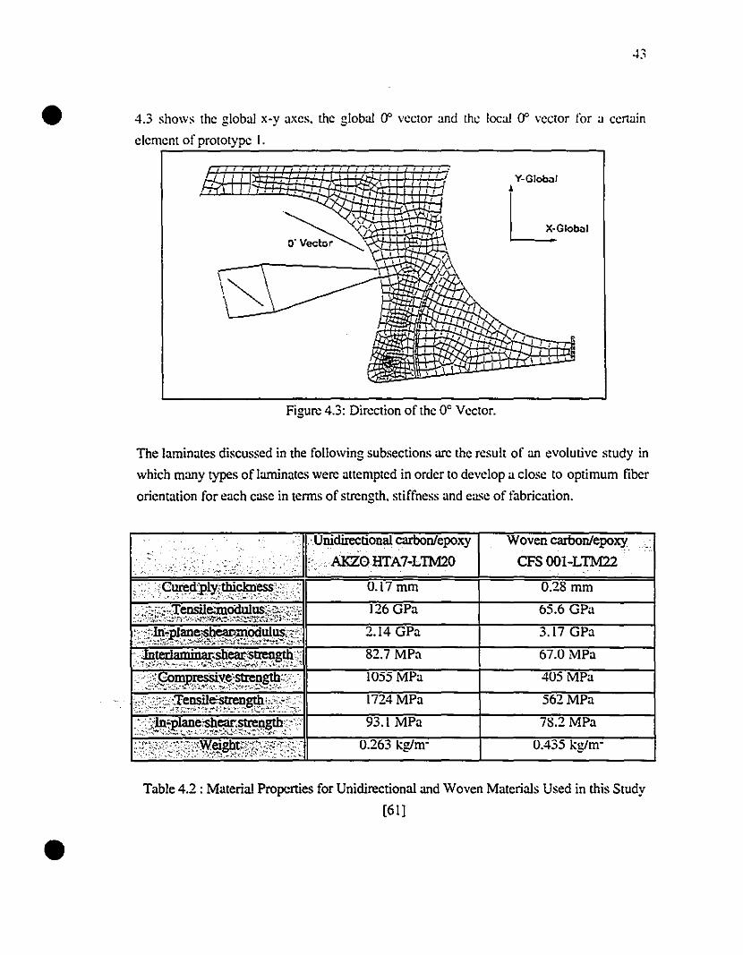
• 4.3 shows the global x-y axes. the global (f vector and thc local (f vector for a certain
clement of prototype 1.
, , , • , , 1 l , , • ,
1 •••• ,., 1..
, . ,. ,, ,,,,, ,
Y-Globi>1•~GIObi>1
Figure 4.3: Direction of the 0° Vector.
The laminates diseussed in the following subseetions arc the result of an evolutive study in
which many types of laminates were attempted in order to develop a close to optimum tiber
orientation for each case in terms of strength. stiffness and case of fabrication.
'Unidirectional carbonlepoxy
,;:,. '>, ,~,;,_:<_ :', "AKZOHTA7-LlM20
Woven carbonlepoxy
CFS OOl-LTM22
1724MPa
93.1 MPa
0.263 kg/m-
562MPa
405 MPa
0.28 mm
78.2MPa
3.17 GPa
67.0 MPa
65.6 GPa
0.435 kg/m-
•Table 4.2: Material Propcrties for Unidireetional and Woven Materials Used in this Study
[61]
•
•
44
4.2.2.1 Laminate Configuration of Prototype 1
Prototype 1 includes 5 differentlaminates containing woven and unidirectional material and
corresponding 10 layups used at different locations. It should be noted that this particular
prototype was modeled and constructed only as a verification of the finite-element analysis
results and construction method. Hence this particular framc couId not bc used in a riding
or racing situation as it was not designed nor conccived to do SO. Unidirectional material
was used in conjunction with the woven material in certain high load arcas as
reinforcement. The regions of high loads were matched with the regions of material
overlap since those regions have more material to support the load. The overlap regions
were at least 25mm which weil exceeds the required load transfer length of only severa!
millimeters. Hence overlaps actually worked as reinforcement. The main front part of the
frame was modeled and made of 2 layers of woven material. The layup changed to 4 layers
in the overlap regions. Also unidircctional reinforcement was added to regions wherc 2
and 4layers of woven material was already present. Thc last layup is in the rear region of
the frame inside the weil where the rcar wheel is located. This region contains only one
layer of woven material. Hence, for this frame, the 5 different laminates include:
1- 1 layer of woven material
2- 2 layers of woven material
3- 21ayers ofwoven material + overlap (4layers woven)
4- 2 layers of woven + unidircctional
5- 2 layers of woven + overlap + unidircctional
Figure 4.4 shows the mesh and the different laminate locations for prototype 1. The
numbers in Figure 4.4 correspond to the laminate numbcrs enumerated above.
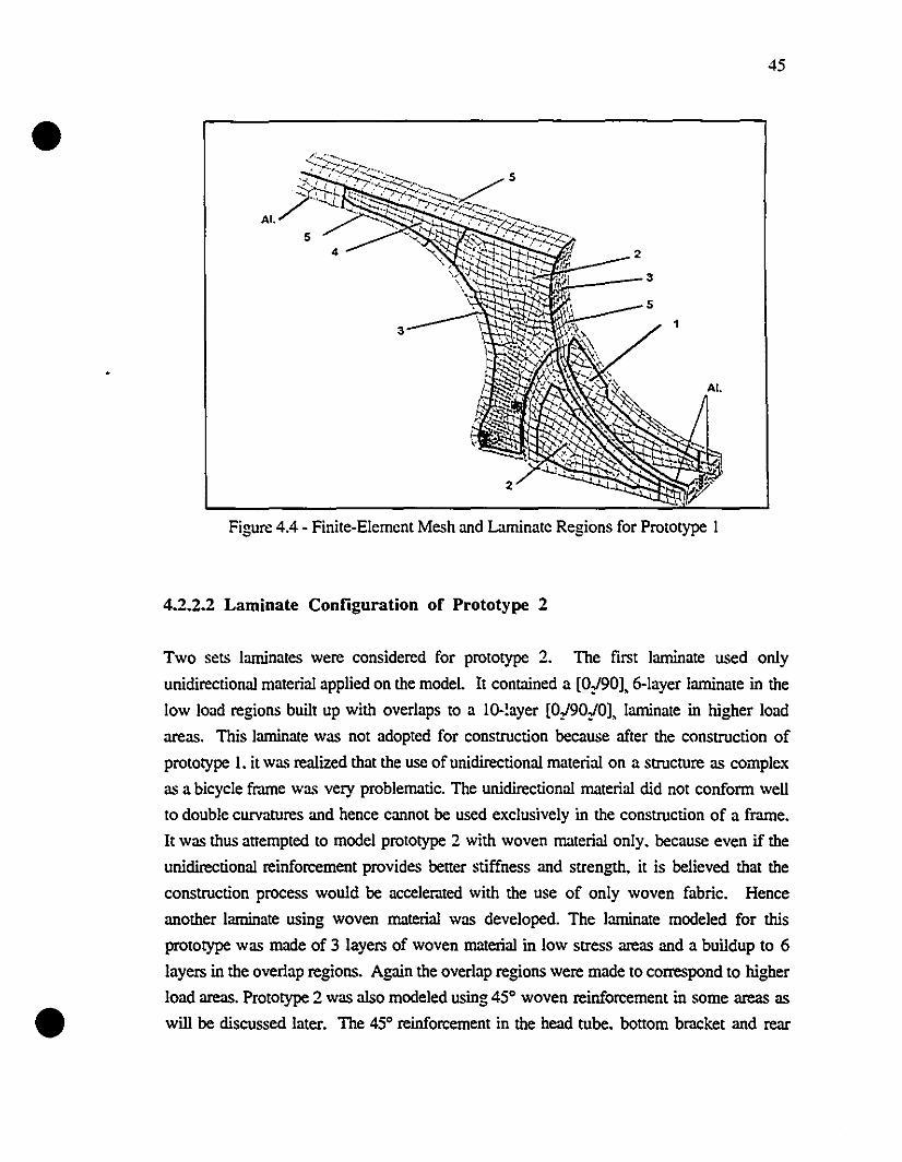
•
•
45
Figure 4.4 - Finite-Element Mesh and Laminatc Regions for Prototype 1
4.2.2.2 Laminate Configuration of Prototype 2
Two sets laminates were considered for prototype 2. The first laminate used only
unidirectional material applied on the mode!. It contained a [0/90],6-layer laminate in the
low load regions built up with overlaps to a ID-!ayer [°/9°/°], laminate in higher load
areas. This laminate was not adopted for construction because after the construction of
prototype 1. it was realized that the use of unidirectional material on a structure as complex
as a bicycle frame was very problematic. The unidirectional material did not conform weU
to double curvatures and hence cannot be used exclusively in the construction of a frame.
It was thus allempted to model prototype 2 with woven material only. because even if the
unidirectional reinforcement provides beller stiffness and strength. it is believed that the
construction process would be accelerated with the use of only woven fabric. Hence
another laminate using woven material was developed. The laminate modeled for this
prototype was made of 3 layers of woven material in low stress areas and a buildup to 6
layers in the overlap regions. Again the overlap regions were made to correspond to higher
10ad areas. Prototype 2 was also modeled using 45° woven reinforcement in sorne areas as
will be discussed later. The 45° reinforcement in the head tube. bollom bracket and rear
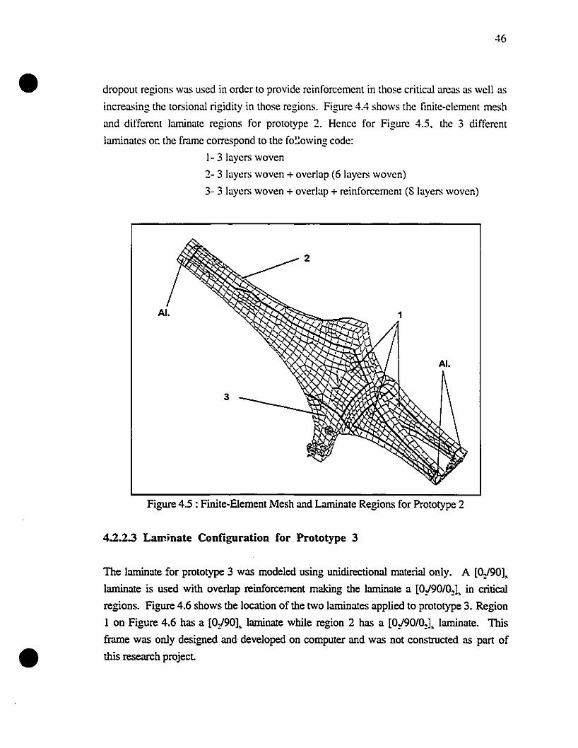
•
•
46
dropout regions was used in order to provide reinforcement in those critical areas as weil as
increasing the torsional rigidity in those regions. Figure 4.4 shows the finite-element mesh
and different laminate regions for prototype 2. Hencc for Figure 4.5. the 3 different
laminates or: the frame correspond to the fo~:owing code:
1- 3 layers woven
2- 3 layers woven + overlap (6 layers woven)
3- 3 layers woven + overlap + reinforcement (8 layers woven)
Figure 4.5 : Finite-Element Mesh and Laminate Regions for Prototype 2
4.2.2.3 Laminate Configuration for Prototype 3
The laminate for prototype 3 was modeled using unidirectional material only. A [0/901,
laminate is used with overlap reinforcement making the laminate a [0/90/02), in critical
regions. Figure 4.6 shows the location of the two laminates applied to prototype 3. Region
1 on Figure 4.6 has a [0/901, laminate while region 2 has a [0/90/02), laminate. This
frame was only designed and developed on computer and was not constructed as part of
this research project
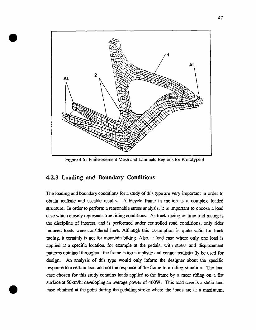
•
•
47
Figure 4.6 : Finite-Element Mesh and Laminate Regions for Prototype 3
4.2.3 Loading and Boundary Conditions
The loading and boundary conditions for a study of this type arc very important in order to
obtain realistic and useable resull~. A bicycle frame in motion is a complex loaded
structure. In order to perform a reasonable stress analysis. it is important to choose a load
case which closely represents true riding conditions. A~ track racing or time trial racing is
the discipline of interest. and is performed under controlled road conditions. only rider
induced loads were considered here. Although this assumption is quite valid for track
racing. it certainly is not for mountain biking. Aiso. a load case where only one load is
applied ::t a specific location. for example at the pedals. with stress and displacement
patterns obtained throughout the frame is too simplistic and cannot realistically he used for
design. An analysis of this type would only inform the designer about the specific
response to a certain load and not the response of the frame to a riding situation. The load
case chosen for this study contains loads applied to the frame by a racer ridinr on a flat
surface at SOkm/hr developing an average power of 400W. This load case is a static load
case obtained al the point during the pedaling stroke where the loads arc at a maximum.
•
•
48
hence this study is for the worst case static scenario. No dynamic analysis was performed
during this research. This load case was calculated analytically and corresponds closcly to
what has bcen measured for the maximum loads in another study where loads at different
application points were measured as a function of cnl11k angle [62]. Loads during this
study were calculated for a conventional geometry 56 cm fmme. thus small corrections
would have to bc made in order to use it for a different size bike. This particular load case
is different from those used in other studies as it considers the non-negligible effect of the
chain and thus renders the loading situation non-symmetric with respect to the major
vertical plane of the bicycle. Hence it is not possible to use symmetry to reduce the numbcr
of clements on the fmme. It is bclieved that this load case reflects reality and is a good
starting point for design. The following is a complete description of the load case
derivation.
4.2.3.1: Starting Hypothesis of Load Case Derivation
-Mass of cyclist: 80 kg hence W=785 N
-Loads on the handJebars by the arrns are unknown
-Angle of the arrns with the handJebars is 45°
-Speed of the bike is 50km/hr = l3.88m1s
-Aerodynamic coefficient: C, = 0.83 [63]
-Surface of the bike-eyclist assembly S = 0.3m2 [63]
-Flat terrain
-Wind speed=O
4.2.3.2: ProbIem Steps
-Caleulate the power expenditure of the cyclist
-Calculate the loads on the pedals from the input power
-Isolate the bicycle and eaieulate the loads on the wheels
-Isolate each wheel
-Calculate the Ioads on the frame
4.3.3.3: Powers InvoIved
-Power developed by the cyclist: PCYc!;M
49
• -Power dissipated by the chain transmission is negleeted ( a chain transmission is typically
98% efficient) [64]
-Power lost duc to air resistance is t'""
-Power dissipated by rolling resistance is neglccted
-Power dissipated by the contact forces perpendicular to the roads arc neglected
(4.1 )
(4.2)hence P""", + P,,;, =0
P~'~'di'i = -P;lir= FOIir V= 0.5 p C, S V' V
= 0.5 x 1.19 x 0.83 x 0.3 x 13.S8~ x 13.88
= 400W
Then at constant speed applying the l;inetic energy theorcm
Plut'"~ = dE/dt = 0
Wherc '1= Riding Velocity= 50 km/h = 13.88 mis
C, = Aerodynamic coefticient = 0.83
S = Frontal arca = 0.30 m'
p = Air density = 1.19 kg/m;
Forcomparison. reference [65] shows a mcer riding at 12. 1mis (43.6 km/hr)
corresponding to a tr.lctive power of 373W and from [66] a time trial power output for a
40.22 km record performance at an avemge speed of 13.6m1s (49km/hr) produces a power
expenditure of more than 373W.
•
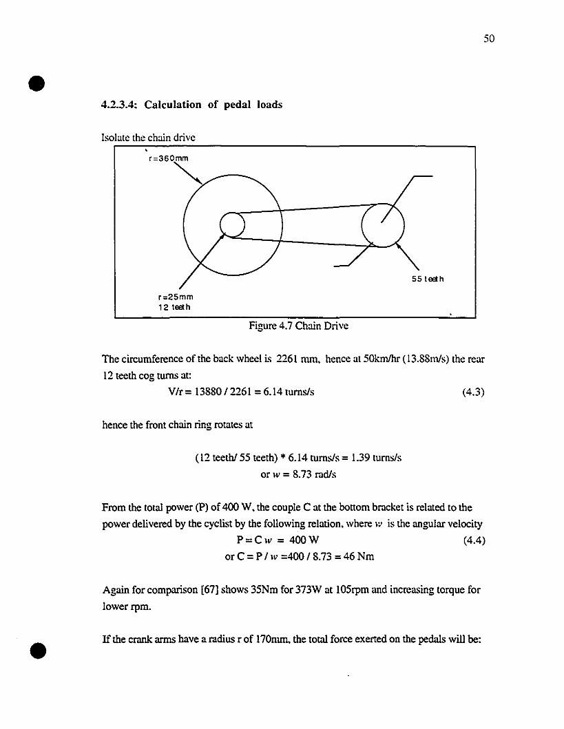
•50
4.2.3.4: Calculation of pedal loads
Isolate the chain drive
r=360~
55tœlh
•
r=25mm12 tœl h
Figure 4.7 Chain Drive
The circumference of the back wheel is 2261 mm, hence at SOkmlhr (13.88m/s) the rear
12 tceth cog tlIms at:
V/r = 13880/2261 = 6.14 tumsls (4.3)
hence the front chain ring rotates at
(12 teethl55 teeth) .. 6.14 tumsls = 1.39 tumsls
or w = 8.73 radis
From the total power (P) of 400 W. the couple C at the bottom bracket is related to the
power delivered by the cyclist by the following relation, where IV is the angular velocity
P=Cw = 400W (4.4)
orC = P Iw =400/8.73 =46 Nm
Agam for comparison [67] shows 35Nm for 373W at 105rpm and increasing torque for
lowerrpm.
If the crank arms have a radius r of 170nun, the total force exerted on the pedals will he:
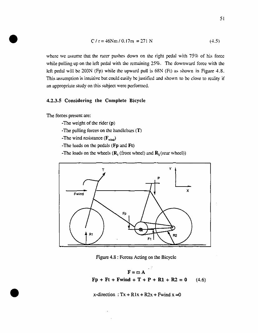
• C/r=46Nm/O.17m =271 N (4.5)
51
•
where we a,'sume tha! the r.\cer pushes down on the right pedal with 75% of his force
while pulling up on the left pedal with the remaining 25%. The downward force with the
left pedal will be 203N (Fp) while the upward pull is 68N (Ft) as shown in Figure 4.8.
This a,'sumplion is intuitive but could ea,~i1y he justified and shown to he dose to reality if
an appropriate study on this subject were performed.
4.2.3.5 Considering the Complete Bicycle
The forces present are:
-The weight of the rider (p)
-The pulling forces on the handlebars (T)
-The wind resistance (Fwlnd)
-The loads on the pedals (Fp and Ft)
-The loads on the wheels (R, (front wheel) and~ (rear wheel))
T
Figure 4.8 : Forces Acting on the Bicycle
F=mA
Fp + Ft + Fwind + T + P + RI + R2 = 0 (4.6)
x-direction: Tx + RIx + R2x + Fwind x =0

• Tx + Rix + R2x + 29 =0
y-direction: Ty + P + Fp + Ft + Rly + R2y = 0
Ty - 785 -203 + 68 +Rly + R2y = 0
Ty -920 + Rly + R2y = 0
(4.7)
(4.8)
52
And the moment equatÏon. taken about a moment a;l:is in the z-directÏon at the bottom
bmcket axis is:
-0.1 P + 0.170 Ft + 0.170 Fp + 0.3 RIx + 0.3 R2x + 0.42 R2y - 0.68 Rly - 0.62 Tx-
0.49 Ty - 0.3 Fwind = 0 (4.9)
-33 + 0.3 RIx + 0.3 R2x + 0.42 R2y - 0.68 Rly - 0.62 Tx - 0.49 Ty - 0.3 Fwind =0
Isolating the front wheel:
•
Figure 4.9: Front Wheel Free Body Diagr.trn
where : FI is the load applied by the wheel on the fr.trne.
RI is the load applied by the ground on the wheel
RIx + FIx =0 (x-dir.)
Rly + Fly = 0 (y dir.)
RIx * radius ofwheel = 0 (moment eq.)
hence Rlx=O (4.10)
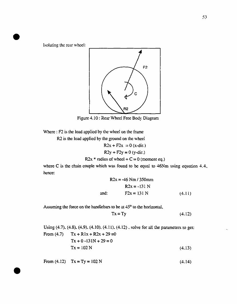
•53
Isolating the rear wheel:
Figure 4. 10 : Rear Wheel Free Body Diagnull
Where : F2 is the load applicd by the wheel on the fr.une
R2 is the load applied by the ground on the wheel
R2x + F2x = 0 (x-dir.)
R2y + F2y = 0 (y-dir.)
R2x * radius of wheel + C = 0 (moment eq.)
where C is the chain couple which was found to bc equal to 46Nm using equation 4.4.
hence:
R2x = -46 Nm 1350mm
R2x=-131 N
and: F2x = 131 N
Assuming the force on the handiebars to bc at 450 to the horizontal.
Tx=Ty
(4.11 )
(4.12)
Using (4.7). (4.8), (4.9). (4.10), (4.11), (4.12) . solve for ail the parameters to get:
From (4.7) Tx + Rix + R2x + 29 =0
Tx + 0 -131N + 29 = 0
Tx= 102N (4.13)
•From (4.12) Tx=Ty= 102N (4.14)
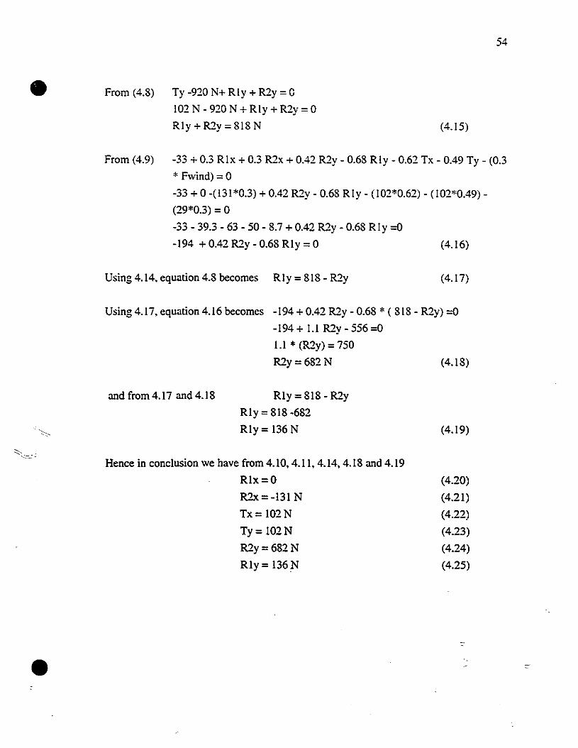
• From (4.8) Ty -920 N+ Rly + R2y = G
102 N - 920 N + Rly + R2y = 0
Rly + R2y = 818 N (4.15)
54
From (4.9) -33 + 0.3 Rix + 0.3 R2x + 0.42 R2y - 0.68 Rly - 0.62 Tx - 0.49 Ty - (0.3
* Fwind) = 0
-33 + 0 -(131*0.3) + 0.42 R2y - 0.68 Rly - (102*0.62) - (102*0.49)
(29*0.3) = 0
-33 - 39.3 - 63 - 50 - 8.7 + 0.42 R2y - 0.68 Rly =0
-194 + 0.42 R2y - 0.68 Rly =0 (4.16)
Using 4.14. equation 4.8 becomes Rly = 818 - R2y (4.17)
Using 4.17, equation 4.16 becomes -194 + 0.42 R2y - 0.68 * (818 - R2y) =0
-194 + I.I R2y - 556 =0
I.I * (R2y) = 750
R2y=682N (4.18)
and from 4.17 and 4.18 Rly = 818 - R2y
Rly = 818 -682
Rly= 136 N (4.19)
•
Hence in conclusion we have from 4.10. 4.11. 4.14. 4.18 and 4.19
Rlx=O
R2x=-131 N
Tx= 102N
Ty= 102N
R2y=682N
Rly= 136N
(4.20)
(4.21)
(4.22)
(4.23)
(4.24)
(4.25)
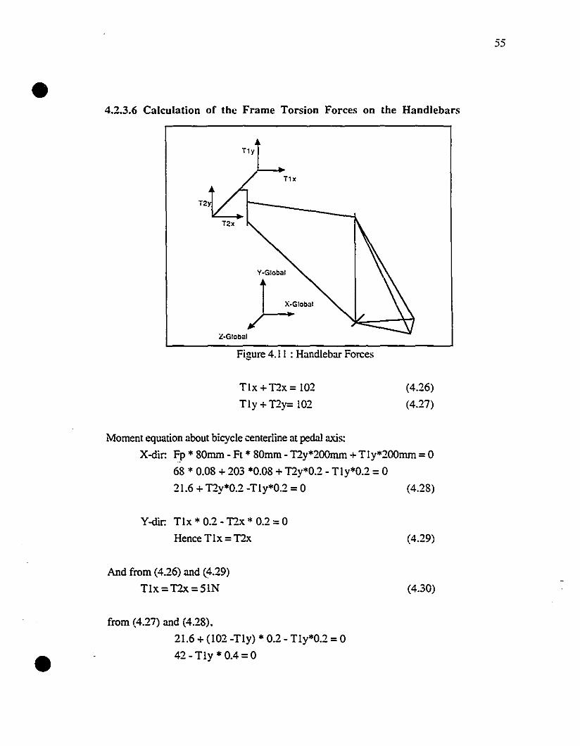
• 4.2.3.6 Calculation of the Frame Torsion Forces on the Handlebars
T1y
Figure 4.1 1 : Handlebar Forces
55
Tlx + T2x = 102
TI Y+ T2y= 102
(4.26)
(4.27)
Moment equation about bicycle centerline at pedal axis:
X-dir: Fp * 80mm - Ft * 80mm· T2y*200mm + Tly*200mm =0
68 * 0.08 + 203 *0.08 + T2y*0.2 - T1y*0.2 = 0
21.6 + T2y*0.2 -Tly*0.2 = 0 (4.28)
•
Y-dir: T1x * 0.2· T2x * 0.2 =0
Hence Tlx =T2x
And from (4.26) and (4.29)
Tlx = T?..x = SIN
from (4.27) and (4.28).
21.6 + (102 -Tly) * 0.2 - Tly*0.2 =0
42 - Tly * 0.4 = 0
(4.29)
(4.30)
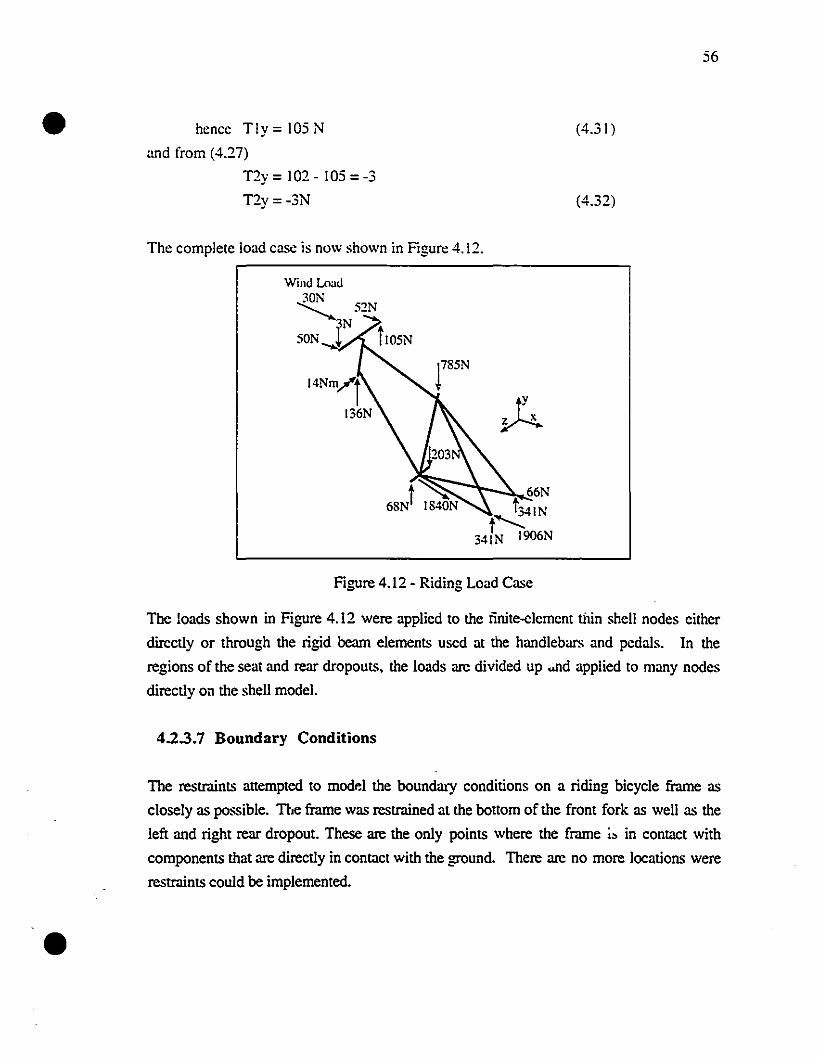
• hencc Tly = lOS N
and from (4.27)
T2y = 102 - 105 =-3
T2y= -3N
The complete load case is now shown in Figure 4.12.
Wind Load
-Z 52N3N
sON ........l tlOSN
~-';:Ic 66Nt34IN
t~341N 1906N
Figure 4.12 - Riding Load Case
(4.31 )
(4.32)
56
•
The loads shown in Figure 4.12 were applied to the iinite-clemcnt tnin shell nodes cither
dircctiy or through the rigid bearn elements used at the handlebars and pedals. In the
regions of the seat and rear dropouts. the loads are divided up ..nd applied to many nodes
directiy on the shell mode!.
4.2.3.7 Boundary Conditions
The restraints anempted to modr-I the boundary conditions on a riding bicycle frame as
c10sely as possible. The frame was restrained al the botlom of the front fork as weil as the
left and right rear dropout. These are the only points where the frame ;~ in contact with
components that are directiy in contact with the ground. There are no more locations were
restraints could he implemented.
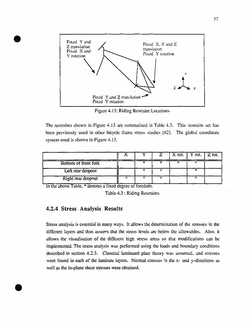
• Fix~ù YandZ translationFix~d X andy rotation
\Fix~ù X. y anù ZtranslationFix~d Y rotation
57
Fix~d Y.and Z trJn,lation.-P"Fix~d Y rotation
Figure 4. 13: Riding Restraint Locations
The restraints shown in Figure 4.13 arc summarizeù in Table 4.3. This rcstrJint set has
been previollsly used in otber bicycle frame stress slUdies [621. The global coordinate
system used is shown in Figure 4.! 3.
[n the above Table. * denotes a ltxed degrce 01 freedom.
Table 4.3 : Riding ResmlÏnts
x y Z X rot. Y rot. Z roI.
Bottom of front tork * * * *Lefi rcar dropout * * *
. Right rear dropout * * * *. ..
4.2.4 Stress Analysis Results
•
Stress anaIysis is essential in many ways. It a110ws the determination of the stresses in the
different Iayers and thus assur"s that the stress levels arc below the a1IowabIcs. AIso. it
aBows the visualisation of the different high stress arcas so that modifications can bc
implemented. The stress analysis was performed using the Ioads and boundary conditions
described in section 4.2.3. Classical Iaminated plate thcory was assumed. and stresses
were found in each of the laminatc Iayers. Nom1a1 stresses in the x· and y-directions as
weB as the in-plane sheur stresses were obtaincd.
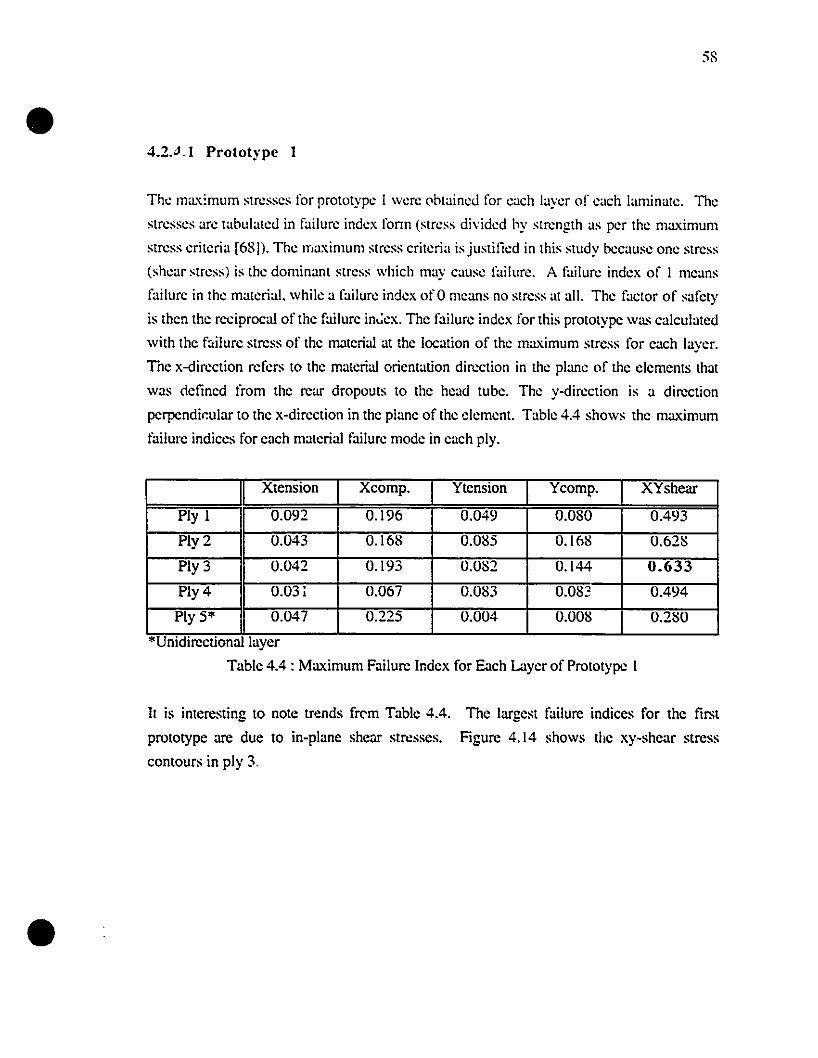
•58
4.2.4.1 Prototype 1
Tht: maximum strt:sses for prototypt: 1 wt:re (lbtaint:ù for t:ach layer of each laminate. The
stresses arc tabulateù in failure index fonn (stress dividt:d by strength as per the maximum
stress criteria [68 D. The maximum stress criteria is justitied in this study because one stress
(shear stress) is the dominant stress which may cause failure. A l"ailure index of 1 means
failure in the material. while a failure index of 0 means no stress al ail. The factor of safety
is then the reciprocal of the failure in':ex. The failure index for lhis prototype was cakulated
with the f::tilure stress of the material at the location of the maximum stress for each layer.
The x-direction refers to the material orientation direction in the plane of the clements that
was c!etined from the rear dropouts to the head tube. The y-direction is a direction
pcrpendic:ular to the x-direction in the plane of the clement. Table 4.4 shows the maximum
l"ailure indices for each material failure mode in each ply.
"Umdlrectlonal layer
Table 4.4 : Maximum Failure Index for E:ich Layer of Prototype 1
Xtension Xcomp. Ytension Ycomp. XYshear
Ply 1 0.092 0.196 0.049 0.080 0.493
Ply 2 0.043 0.168 0.085 0.168 0.628
Ply 3 0.042 0.193 0.082 0.144 0.633
Ply 4 0.031 0.067 0.083 0.083 0.494
Ply 5'" 0.047 0.225 0.004 0.008 0.280..
It is interesting to note trends fr('m Table 4.4.
prototype arc due to in-plane shear stresses.
contours in ply 3.
The largest failure indices for the tirst
Figure 4.14 shows the xy-shear stress
•
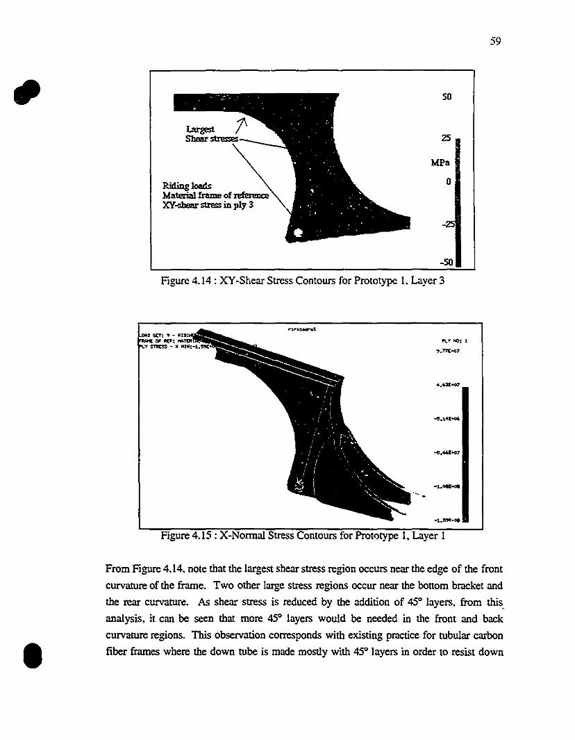
59
RidinglœdsMateri2l1 frame of referenœXY-sbœr stress in ply 3
50
2S
MPa
o
-50
Figure 4.14 : XY-Shear Stress Contours for Prototype 1. Layer 3
1
Figure 4.15 : X-Normal Stress Contours for Prot<:>type 1. Layer 1
From Figure 4.14. note that the largest shear stress region occurs near the edge of the front
curvature of the frame. Two other large stress regions occur near the bonom bracket and
the rear curvature. As shear stress is reduced by the addition of 45° layers. from this.
analysis. it can be seen that more 45° layers would be needed in the front and back
curvature regions. This observation corresponds with existing practice for tubular carbon
fiber frames where the down tube is made mostly with 45° layers in order to resist down
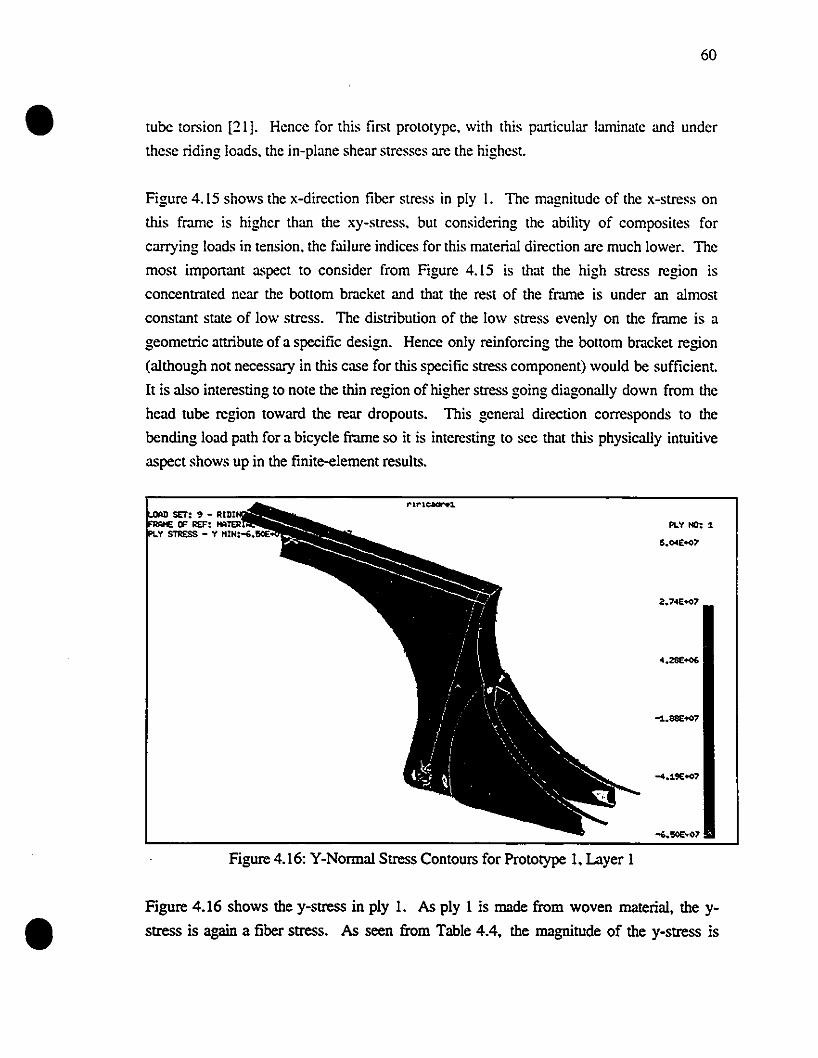
•60
tube torsion [21]. Hence for this first prototype. with this particular laminate and under
these riding loads. the in-plane shear stresses are the highesl.
Figure 4.15 shows the x-direction fiber stress in ply 1. The magnitude of the x-stress on
this frame is higher than the xy-stress. but considering the abiliry of composites for
carrying loads in tension. the failure indices for this malerial direction are much lower. The
most important aspect to consider from Figure 4.15 is that the high stress region is
conccntrated near the bollom bracket and that the rest of the frame is under an almost
constant Slate of low stress. The distribution of the low stress evenly on the frame is a
geometric allribute of a specific design. Hence only reinforcing the bollom bracket region
(although not necessary in this case for this specific stress component) would be sufficienl.
It is also interesting to note the thin region of higher stress going diagonally down from the
head tube region toward the rear dropouts. This general direction corresponds to the
bending load path for a bicycle frame so it is interesting to see that this physically intuitive
aspect shows up in the finite-element results.
PLV HO: 1
15.04E+()7
Figure 4.16: Y-Normal Stress Contours for Prototype 1. Layer 1
Figure 4.16 shows the y-stress in ply 1. As ply 1 is made from woven material. the y
stress is again a fiber stress. As seen from Table 4.4. the magnitude of the y-stress is
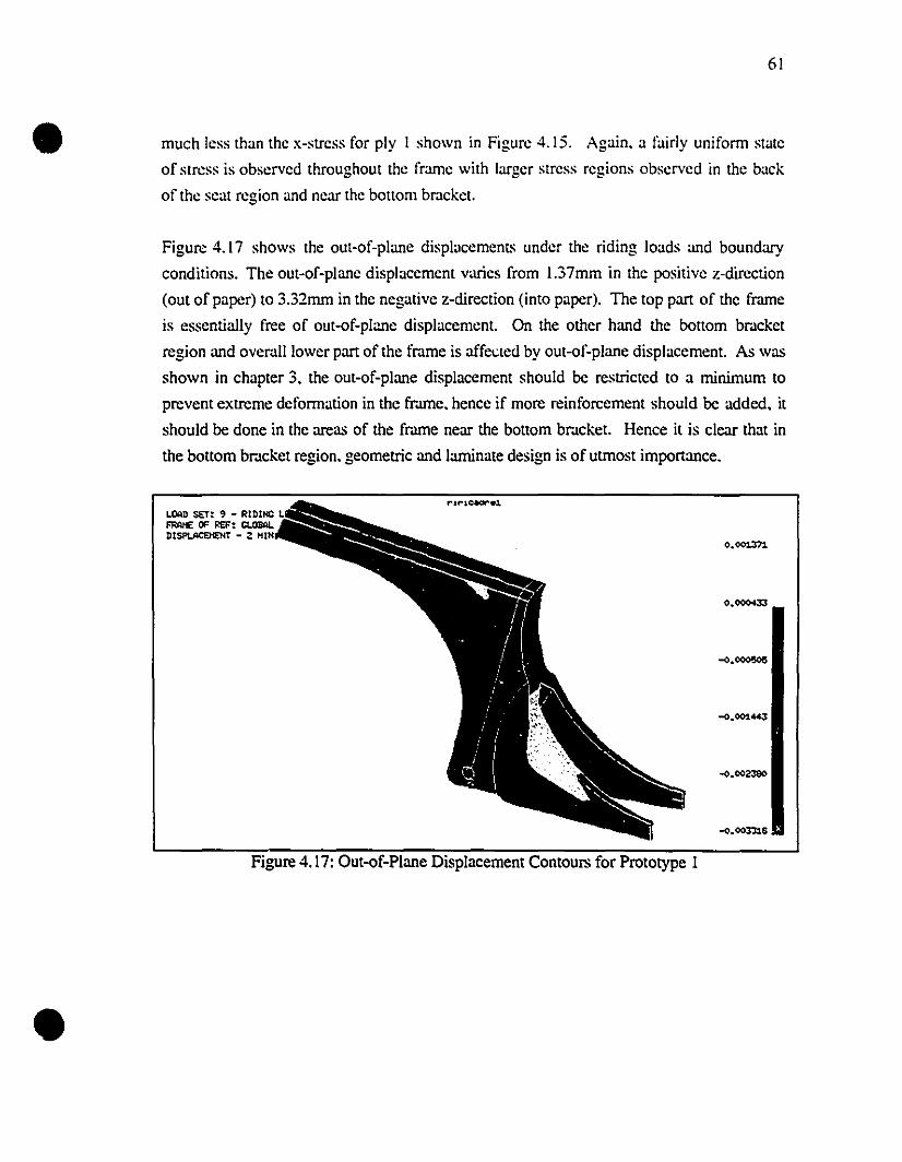
•
•
61
much Jess than the x-stress for ply 1 shown in Figure 4.15. Again. a fairly uniform state
of stress is observed throughout the frame with larger stress regions observed in the baek
of the seat region and near the bOllom br.lcket.
Figure 4.17 shows the out-of-plane displacemenl~ under the riding loads and boundary
conditions. The out-of-plane displacement varies from 1.37mm in the positive z-direction
(out ofpapcr) to 3.32mm in the negative z-direction (into paper). The top part of the frame
is essentially free of out-of-plime displacemcnt. On the other hand the bollom br.lcket
region and ovemll lower part of the frame is affected by out-of-plane displacement. As was
shown in chapter 3. the out-of-plane displacement should be restricted to a minimum to
prevent extreme defonnation in the frame. hencc if more reinforcement should be added, it
should be done in the areas of the frame near the bOllom bracket. Hence it is clear that in
the bottom bmcket region. geometric and larninate design is of utrnost importance.
0.001371
0.0000I33
-0.001443
-o.oo3'h&
Figure 4.17: Out-of-Plane Displacement Contours for Prototype 1
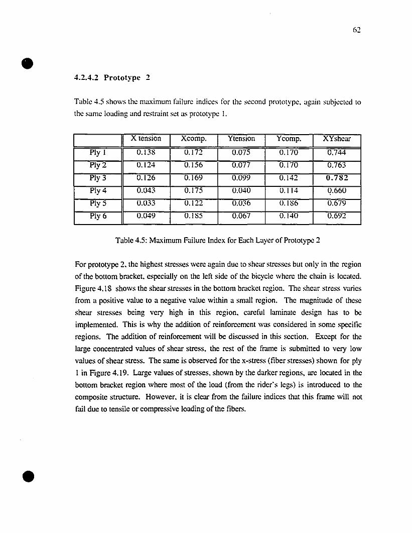
•
•
62
4.2.4.2 Prototype 2
Table 4.5 shows the m:Lximum failurc indices for the second prototype. again subjected to
the same loading and rcstr.lint set as prototype 1.
X tension Xcomp. Ytension Ycomp. XYshear
Ply 1 0.138 0.172 0.075 0.170 0.744
Ply 2 0.124 0.156 0.077 0.170 0.763
Ply 3 0.126 0.169 0.099 0.142 0.782
Ply 4 0.043 0.175 0.040 0.114 0.660
Ply 5 0.033 0.122 0.036 0.186 0.679
Ply 6 0.049 0.185 0.067 0.140 0.692
Table 4.5: Maximum Failure Index for Each Layer of Prototype 2
For prototype 2. the highest stresses were again duc to shear stresses but only in the region
of the bollom bmcket. espeeially on the left side of the bicycle where the chain is locmed.
Figure 4.18 shows the shear stresses in the bollom br.leket region. The shear stress varies
l'rom a positive value to a negative value within a small region. The magnitude of these
shear stresses being very high in this region. carcful laminate design has to bc
implemented. This is why the addition of reinforcement was eonsidered in some speeilie
regions. The addition of reinforcement will bc diseussed in this section. Exeept for the
large concentrated values of shear stress. the rest of the fr.ln1e is submilled to very low
values of shear stress. The same is observed for the x-stress (liber stresses) shown for ply
1 in Figure 4.19. Large values of stresses. shown by the darker regions. arc located in the
bOllom bmeket region where most of the load (l'rom the rider's legs) is introduced to the
composite structure. However. it is clcar l'rom the failurc indices that this fr.ln1e will not
l'ail duc to tensile or compressive loading of the libers.
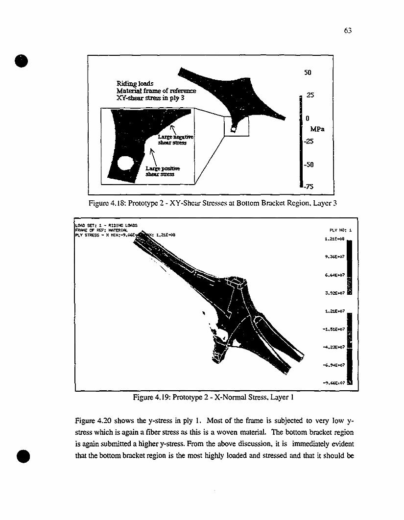
63
•RidiIlg loadsMaterial frame of referenœXY-shear stress in ply 3
50
25
oMPa
-25
-50
-75
Figure 4.18: Prototype 2 - XY-Shear Stresses at Bollom Br.lcket Region. Layer 3
LOAD SET: 1 - Rl~JHC LQMDS~ OF' REF: HATERIAl.PLy STRESS - X HIH:-'.b6E
PLY HO: 1
1.21E+oS
9.JŒ+o7
6.64E+o7
J.92E+o7
,
~::I
:::1-'.66[..01
•
Figure 4.19: Prototype 2 - X-Normal Stress. Layer 1
Figure 4.20 shows the y-stress in ply 1. Most of the frame is subjected to very low y
stress which is again a fiber stress as this is a woven material. The bollom bracket region
is again submitted a higher y-stress. From the above discussion. it is irnmediately evident
that the bottom bracket region is the most highly loaded and stressed and that it should be
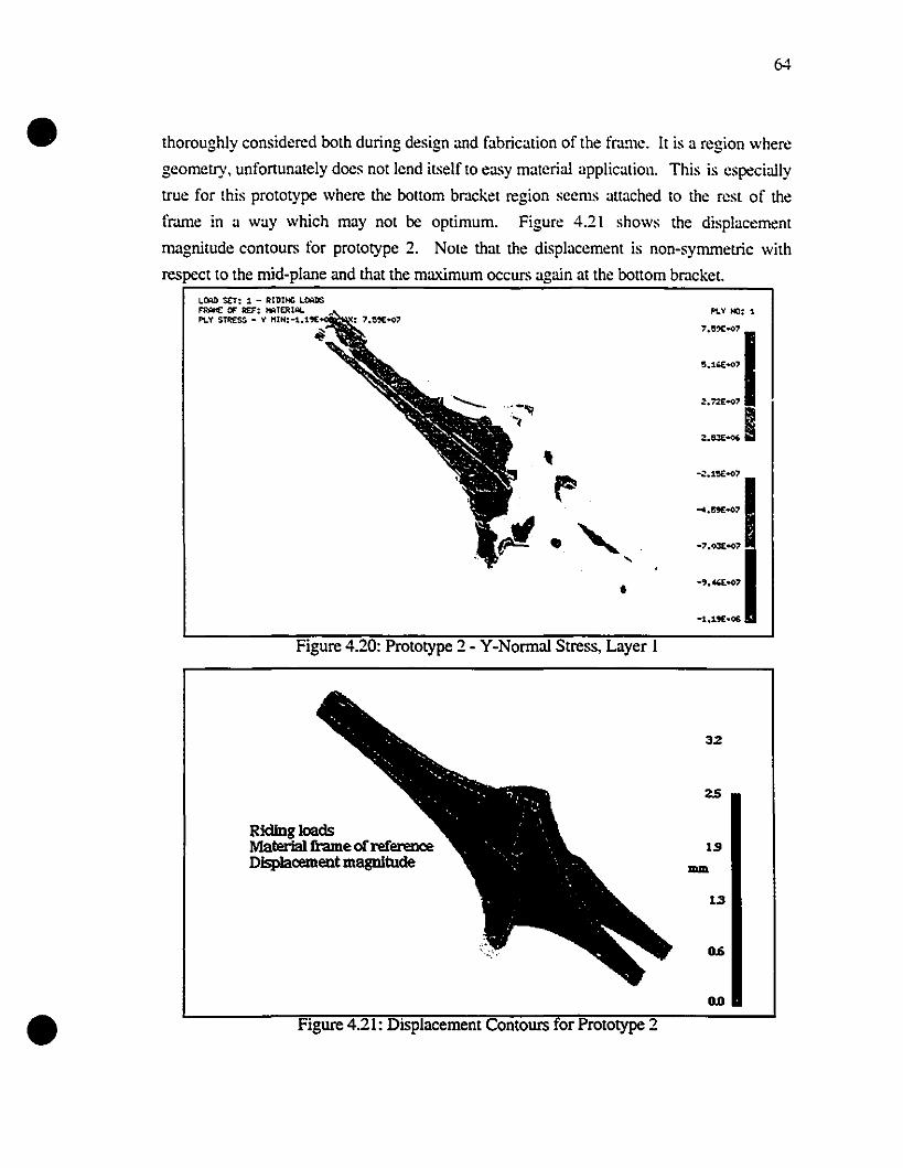
•64
thoroughly considered both during design and fabrication of the frame. It is a region where
geometry, unfortunately docs not lend itselfto easy material application. This is especially
true for this prototype where the bouom br.lcket region seems auached to the rest of the
fmme in a way which may not he optimum. Figure 4.21 shows the displacement
magnitude contours for prototype 2. Note that the displaccment is non-syrnmetric with
respect to the mid-plane and that the maximum occurs again at the bouom bmcket.
•
L.Mrl sa: 1 - RIDIHC LOoUlS~ OF Ra: Ht:llERIALPLV S~ - v HIN:-l.1'~
~
•
Figure 4.20: Prototype 2 - Y-Normal Stress, Layer 1
Rlcllng loadsMaterla1!hlmeofreferenœDIsplaœment magnitude
Figure 4.21: Displacement Contours or Prototype 2
PLY HO: 1
::::::1::::1
32
1.9-1.3
D.6
DD
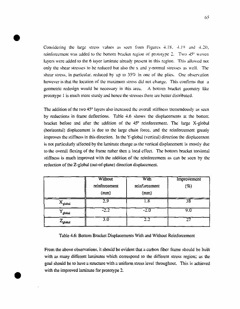
•
•
65
Considering the large stress values as seen l'rom Figures 4.1 S. -L1lJ and 4.20.
rcinforcement was added to the ho[[om hrack<:t r<:gion of prololype 2. Two 45° wo"<:11
layers were added to the 6 iayer laminate already pr<:sent in this r<:gion. This allow<:d not
only the shear slresses to be r<:duced bUl also the x and y-normal stresses as weil. The
shear slress. in panicular. reduced hy up ID 35<;" in one of Ihe plies. One observation
howe"er is that the location of the maximum stress did not change. This conlirms that a
geometric redesign would be necessary in this area. A ho[[om bracket geometry like
prolotype 1 is much more slllrdy and hence the stresses there arc better distrihuted.
The addition of the lWO 450 layers aIso incrcased the o"er.lll stiffness tremendously as seen
by reductions in fmme del1ections. Table 4.6 shows the displacements al the botton'.
br.lckct before and alier the addition of the 450 reinforcement. The largc X-global
(horizontal) displacemcnt is due to the large chain force. and thc reinforccmcnt greatly
improvcs thc stiffness in this dircction. In thc Y-global (vcnical) direction thc dist'lacemcnt
is not particularly affected by the laminate change as thc vcttical displaccmcnt is mostly duc
to the ovcmIl llexing of the fmmc mthcr thcn a local cffcct. Thc bottom br.lckct torsiona]
stiffncss is much improved with the addition of thc reinforcemcnt as can be seen by thc
reduction ofthc Z-global (out-of-plane) direction displaccment.
Without With Improvement
reinforcement reinf;>rcement (%)(mm) (mm)
Xg1obol2.9 1.8 38
Yg1obol-2.2 -2.0 9.0
Zglobol 3.0 2.2 27
Table 4.6: Bollom Brdcket Displacements With and Without Reinforcement
From the above observations. il should bc evident that a carbon liber fmme should be built
with as many different Ianunates \Vhich correspond to the diftèrent stress region: as the
goal should be to have a structure \Vith a uniform stress level throughout. This is achieved
\Vith the improved laminate for prototype 2.
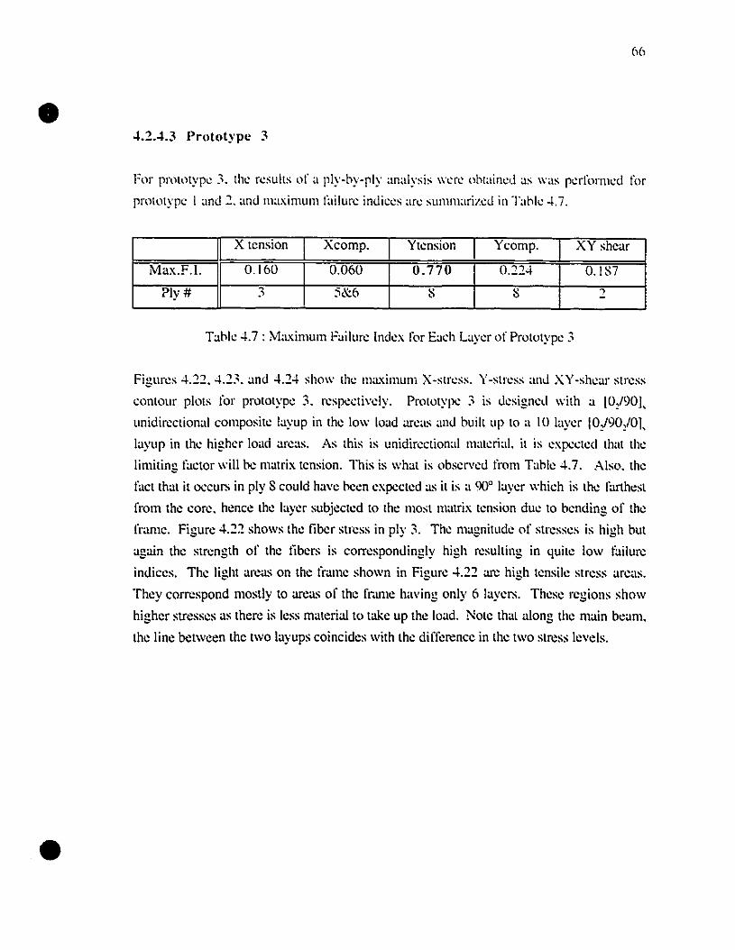
•
•
66
~.2.4.3 Prototype 3
For pmllllype 3. the resuils of a ply-by-ply analysis were oblained as was perfonned for
prototype 1and 2. and maximum failure indices arc summarized in T:lble -1.7.
X tcnsion Xcomp. Ytcnsion Ycomp. XY shcar
Max.F.1. 0.160 0.060 0.770 0.22-1 0.IS7
?ly# 3 5&6 S S ~
Table -1.7 : M:lximum FailllJ'e Index for Eaeh Layer of Prototype 3
Figures 4.22. -1.23. and 4.24 show the maximum X-stress. Y-stress and XY-shear stress
contour plots for prolotype 3. respeetivcly. Prolotype 3 is designed with a [0,l90L
unidirectional composite layup in the low load are:lS :md built up to a lU laver IOJ90J01.. - - '\
layup in the higher load area.s. As this is unidireclional materiaI. it is expceted that the
limiling factor will De matrix tcnsion. This is what is obscl'\'cd l'rom Table -1.7. Aiso. thc
fact that it occurs in ply S could have hcen expccted a.s it is a 90° layer which is the farthest
from the core. hence thc layer subjected to the most mmrix tcnsion duc to bending of the
li·ame. Figure -1.22 shows the liber stress in ply 3. The magnitude of stresses is high but
again the strength of the libers is correspondingly high resulting in quite low l'ailure
indices. The light area.s on the frame shown in Figure -1.22 arc high tensile stress are:lS.
They correspond mostly to arca.s of the frùl11e having only 6 layers. These regions show
highcr stresscs as therc is less matcrialto take up thc load. Note thal along thc main beam.
the linc between thc two layups coincides with the difference in lhe two stress levels.
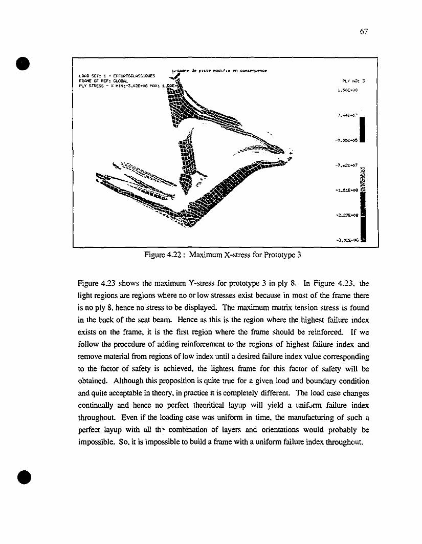
•
•
67
Pl..~' NO: 3
Figure 4.22: Maximum X-stress for Prototype 3
Figure 4.23 shows the maximum Y-stress for prototype 3 in ply 8. ln Figure 4.23. the
light regions are regions where no or low stresses exist because in most of the frame there
is no ply 8. hence no stress to be displayed. The maximum matrix ten~ion stress is found
in the back of the seat bearn. Hence as this is the region where the highest failure mdex
exists on the frame. it is the first region where the frame should be reinforced. If we
follow the procedure of adding reinforcement to the regions of highest failure index and
remove material from regions of low index until a desired failure index value corresponding
to the factor of safety is achieved. the lightest frame for this factor of safety will be
obtained. Although this proposition is quite true for a given load and boundary condition
and quite acceptable in theory. in practice it is compJeteJy different. The Joad case changes
continually and hence no perfect theoritical layup will yieJd a unif."rm failure index
throughout. Even if the loading case was uniform in time. the manufacturing of such a
perfect Jayup with ail th' combination of layers and orientations would probably be
impossible. So. it is impossible to build a frame with a uniform failure index through(>ut.
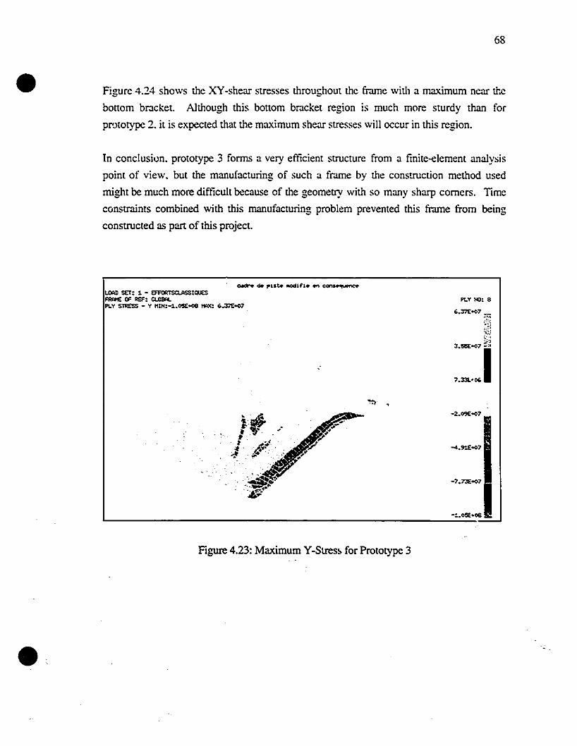
•68
Figure 4.24 shows the XY-shear stresses throughout the frame with a maximum near the
bonom bracket. A1though this boltom bracket region is mueh more sturdy than for
prototype 2. it is expeeted that the maximum shear stresses will occur in this region.
In conclusiun. prototype 3 forms a very efficient structure from a finite-element analysis
point of view, but the manufacturing of such a frame by the construction method used
might be much more difficult because of the geometry with so many sharp corners. Time
constraints combined with this manufacturing problem prevented tbis frame from being
constructed as part of tbis project.
•
t.OAJl SET: 1 - EFFORTSQ.ASSIQUESFRSltIE OF REF: CLDBALPLY STRESS - y HIH:-1.O'SE+08 HAX: 6.3:E-.o7
Figure 4.23: Maximum Y-Stres~ for Prototype 3
PLY HO: 8
'.:rn:-.o7 _
~
::::1
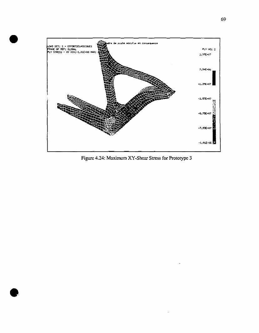
•
•
l):ID SET: :. - ~Sa.t:.SSIQUES
F'Pl:lI1( OF' REF: Cl"OMl.PLv ~rm:~ - ~ HtN:-1.01C--oa lW<:
Figure 4.24: Maximum XY-Shear Stress for Prototype 3
69
•
•
70
Chapter 5
Composite Frame Fabrication and Testing
5.1 Introduction
As previously discussed. the second pan of this project includes the construction of two
carbonlepoxy monocoque bicycle frames. Prototypes 1 and 2 wcre constructed. This
section will explain in detail the method. instruments. and matcrials uscd in the construction
of those frames. The final curing of prototypes 1 and 2 took place in Scptembcr 1994 and
June 1995 respectively. The methods used to test the frames will also be explained. The
test results for the composite frames will be compared to tests performed on c1assic metallic
frames.
5.2 Rationale for Manufacturing Method
The manufacturing method chosen is the thermoset prepreg-vacuum bagging method
outlined in section 2.5.4. It was chosen because as this study is still in the prototyping
stage, only one or two models of each frame was initially planned. Hence an expensive
aluminum or composite mold would not be appropriate. The thermoset prepreg material
was chosen over the wet lay-up and thermoplastic composite because it proyides good
mechanical properties, the correct fiber to resin volume fraction, an appropriatc tackiness
for fabrication and a relatively low cost compared to woven or unidirectional thermoplastic
prepregs. It is clear that fmal production of frames, large or small. should use an exterior
mold either with an internai bladder or an internai core, both for fabrication time reduction
and appropriate surface finish. For the reasons mentioned above, it was clear that the
thermoset prepreg-vacuum bagging technique was the best choice for this project.
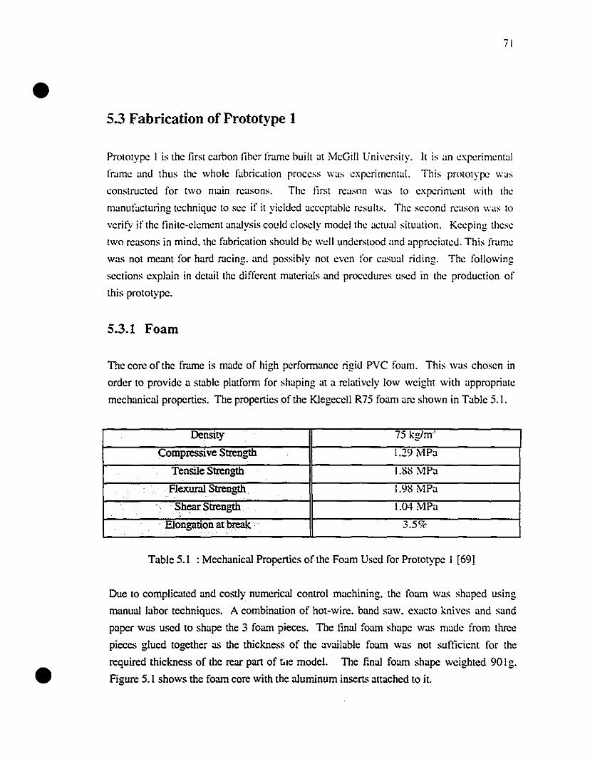
•
•
71
5.3 Fabrication of Prototype 1
Prototype 1 is the first carbon liber fr.lme huilt at McGili Universily. It is an experimental
fr.lme .md thus the whole fabrication process \Vas experimental. This prolotype \Vas
constructed for two main reasons. The tirst reason \Vas to experiment \Vith the
manufactUl;ng technique to see if it yielded acceptable resulls. The second reason \V.IS to
verify if the finite-e1ement analysis COl!ld c10sely model the actual situation. Keeping these
Iwo rea..~ons in mind. the fabrication should be \Vdl underslOod and appreciated. This t'rame
Wa..~ not meant for hard mcing. and possibly not even for casual riding. The following
sections explain in detai! the differcnt materials and procedures used in the production of
this prototype.
5.3.1 Foam
The core of the fmme is made of high performance rigid PVC foam. This was chosen in
order to provide a stable platform for shaping at a relatively low weight with appropriatt:
mechanieal properties. The properties of the Klegecell R75 foam arc shown in Table 5.1.
Density 75 kg/m'
Compressive Strength 1.29 MPa
TensileStrength I.Sl.'i MPa
Flexur:ù Strength 1.9S MPa.' . . .
. ShearStrength 1.04 MPa. .
. Elongation at break . 3.5%..... '.'
Table 5.1 : Meehanical Properties of the Foam Used for Prototype 1 [69]
Due to eomplicated and costly numerieal control machining. the foam was shaped using
manual labor techniques. A combination of hot-wire. band saw. exaeto knives and sand
paper was used to shape the 3 foam pieees. The linal foam shape wa..~ made from tmee
pieces glued together as the thiekness of the available foam wa..~ not suflicient for the
required thiekness of the rear part of tile model. The final foam shape weighted 901g.
Figure 5.1 shows the foam core with the a1uminum inscrts attached to il.
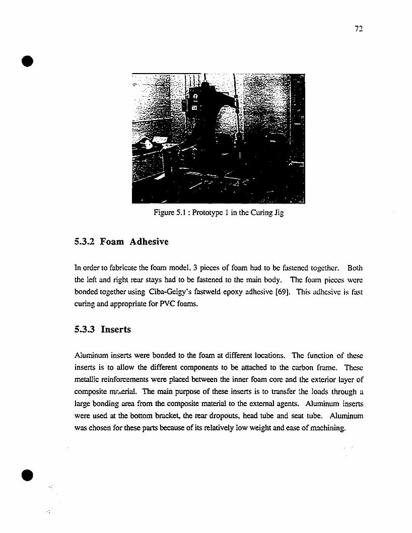
•
•
Figure 5.1 : Prototype 1 in the Curing lig
5.3.2 Foam Adhesive
In order to fabricate the foarn mode!. 3 picces of foarn had to be fastened togcthcr. Both
the left and right rear stays had to be fastened to the main body. The fa.lm pieces wcre
bonded together using Ciba-Geigy's fastweld epoxy adhesive [69]. This adhesive is fast
curing and appropriate for PVC foarns.
5.3.3 Inserts
Aluminum inserts were bonded to the foarn at different locations. Thc function of these
inserts is to allow the different components to be attached to the carbon fnune. These
metallic reinforcements were placed between the inner foarn core and the extcrior layer of
composite mr"erial. The main purpose of these inserts is to transfer :he loads through a
large bonding area from the composite material to the extemal agents. Aluminum inserts
were used at the bottom bracket, the rear dropouts. head tube and scat tube. Aluminum
was chosen for these parts because of its relatively low weight and ease of nuchining.
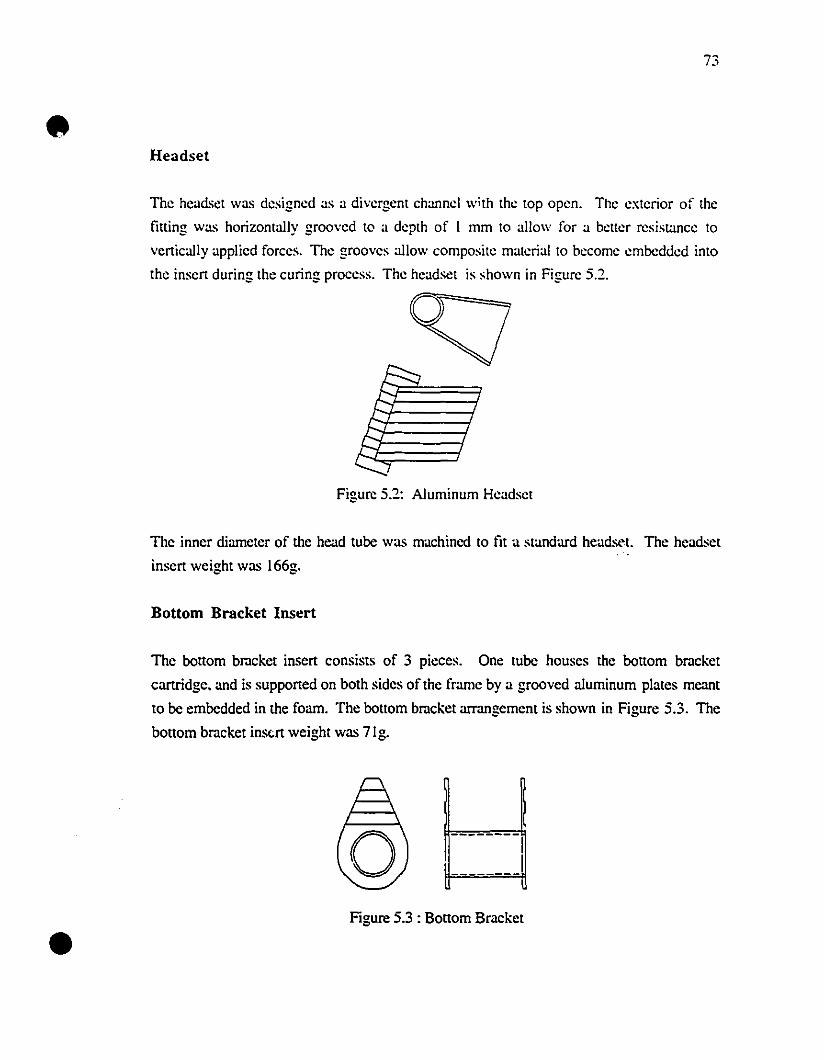
•
•
73
Headset
The head~et was designed as a divergent channel w;th the top open. The exterior of the
fining was horizontally grooved to a depth of 1 mm to allow for a beller resistance to
vertically applied forces. The grooves a1low composite material to become embedded into
the insert during the curing process. The headset is shown in Figure 5.:2.
Figure 5.:2: Aluminum Headset
The inner diameter of the head tube was machined to fit a standard heads<,l. The headset
insert weight was l66g.
Bottom Bracket losert
The bottom bracket insert consists of 3 pieces. One tube houses the bonom bracket
cartridge. and is supported on both sides of the frame by a grooved a1uminum plates meant
to be embedded in the foam. The bonom bracket armngement is shown in Figure 5.3. The
bonom bracket inscrt weight was 7Ig.
Figure 5.3 : BOllom Bracket
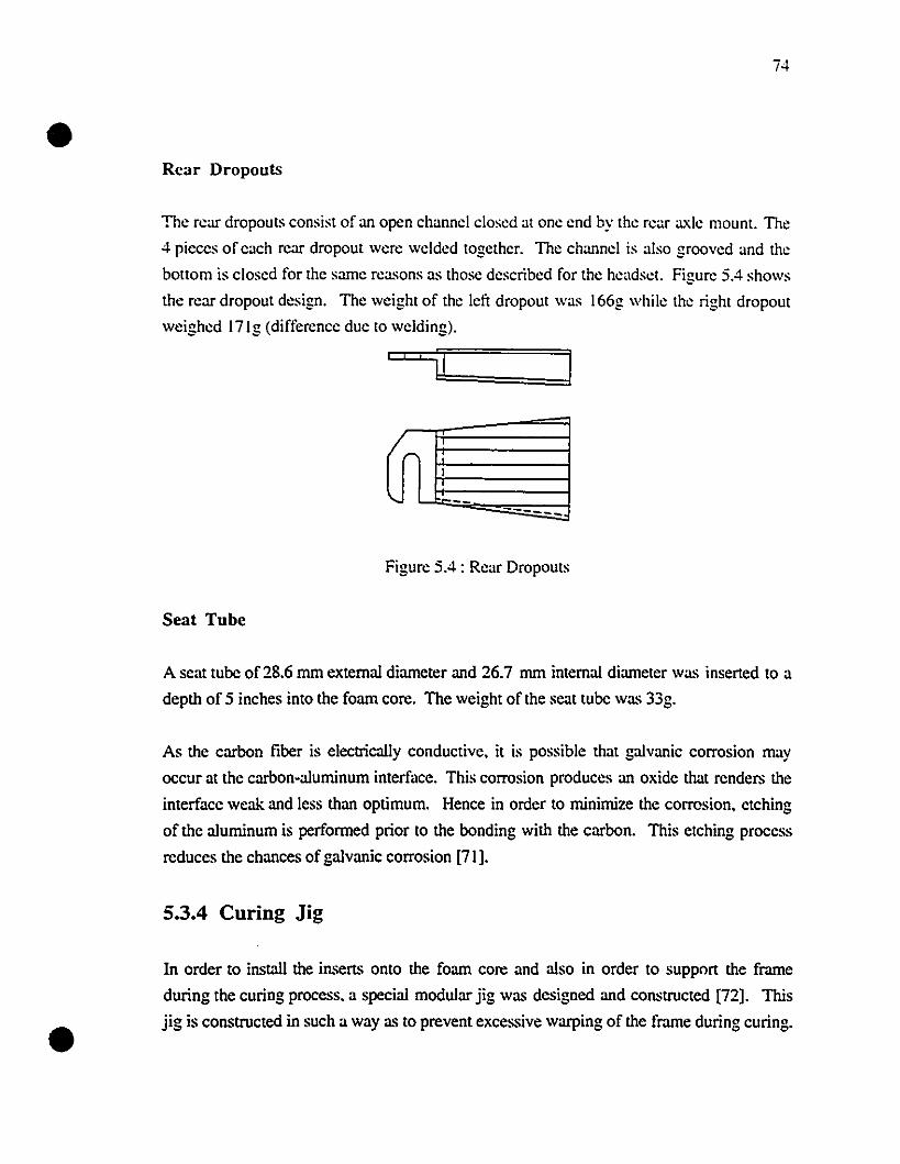
•
•
74
Rcar Dropouts
The rear dropouts consist of an open channel closed at one end by the rear axle mOUnl. The
4 picccs of cach rear dropout were wclded togethcr. The channel is also grooved and the
bollom is closed for the sume rea.~ons as those described for the headsel. Figure 5.4 shows
the rear dropout design. The weight of the left dropout was 166g while the right dropout
weighed l7lg (difference duc to welding).
,....1
'- ,;..-- ------
Figure 5.4 : Rear Dropouts
Scat Tube
A se:1t tube of 28.6 mm extemal diumeter and 26.7 mm internai diumeter was inserted to a
depth of 5 inches into the foum core. The weight of the seut tube Wa.~ 33g.
As the carbon fiber is electrically conductive, it is possible that galvanic corrosion may
occur at the carbon-aluminum interface. This corrosion produces an oxide that renders the
interface weak and less than optimum. Hence in order to minimize the corrosion, etching
of the aluminum is perforrned prior to the bonding with the carbon. This etching process
reduces the chances of galvanic corrosion [71].
5.3.4 Curing Jig
In order to install the inserts onto the foum core and also in order to support the frame
during the curing process. a special modular jig was dcsigned and constructed [72]. This
jig is constructed in such a way as to prevent excessive warping of thc frame during curing.
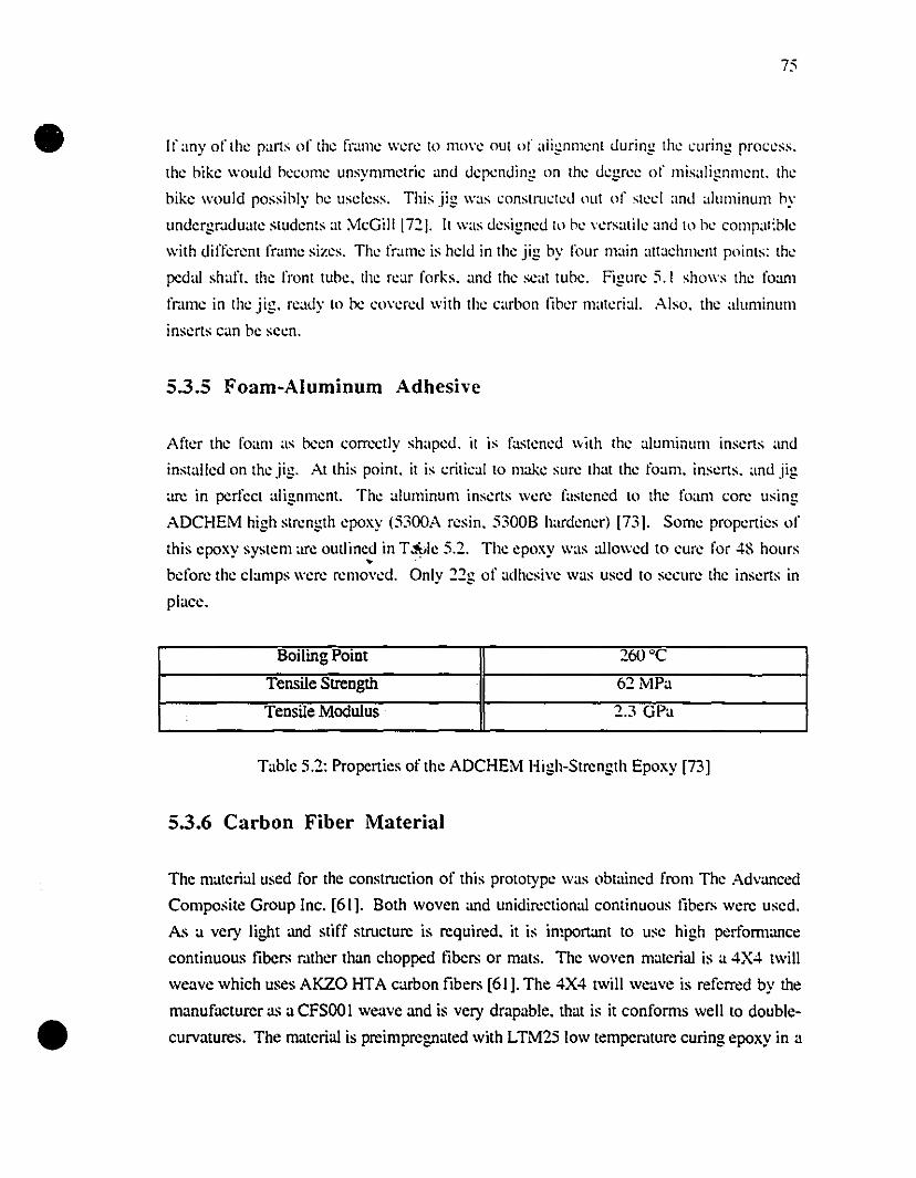
•
•
75
If any of Ihe parts of the frame were to move out of alignment ùuring the curing proccss.
the hike woulù hecome unsymmelric anù ùcpenùing on Ihe ùegrcc of misalignment. Ihe
hike would possihly he uscless. This jig was conslructed out of sleel and aluminum hy
unùergr.tduate students at McGilllnj. Il was designcd 10 he versatile and to he comp;ll:hle
with diffcrent framc sizes. The frame is helù in the jig by four main attachment points: Ihe
pcdal shart. the front tuhe. Ihe l'car forks. and the scat tuhe. Figure 5.1 shows the foam
fr.tme in Ihe jig. reaùy la he eovereù with the carbon liher materia!. Also. the aluminum
inserts can be seen.
5.3.5 Foam-Aluminum Adhesive
After the foam as heen corrcctly shapeù. il is f;lsteneù \Vilh the alumioum inserts and
installed on Ihe jig. At this point. it is critieal to make sure th;lt the foam. inserts. ;IOÙ jig
arc in pcrfect alignment. The aluminum inserts were fastened ta the foam core using
ADCHEM high strength epoxy (5300A resin. 5300B hardener) [731. Sorne properties of
this epoxy system arc outlineù in T~le 5.2. The epoxy was ;ùloweù ta cure for 48 hallrs~ .
before the clamps were removed. Only 22g of adhesive was used to seellre the inserts in
place.
Boiling Point 260°C
Tensile Strength 62MPa
Tensile Modulus 2.3 GPa
Table 5.2: Propcrties of the ADCHEM High-Strength Epaxy [73J
5.3.6 Carbon Fiber Material
The materialused for the construction of this prototype was obtained l'rom The Advanced
Composite Group Inc. [61 J. Both woven and unidirectional continuous libers were used.
As a very ligbt and stiff structure is required. it is important to use high performance
cominuous libers r.tther than chopped libers or mats. The woven material is a 4X4 twill
weave which uses AKZO HTA carbon fibers [61 J. The 4X4 twill weave is referrcd by the
manufacturer as a CFSOO1 weave and is very drapable. that is it conforms weil to double
curvatures. The matcrial is preimpregnated with LTM25 low tempcr.tture curing epoxy in a
•
•
76
B-stage. The unidirectional material uses the same lihers and epoxy system as the \Voven
material. The mechanical properties of hoth the unidireetional malerial and woven m;llerial
can he found in Table 4.2. The epoxy .-:ystem is low tempcmture curing (56°C) in order 10
he compatible with the maximum temper.lturc the foam ean withstand (77°0. The cured
thickness of one layer is 0.28 mm for the \Voven material and 0.17 mm for the
unidirectional material.
5.3.7 Material Orientation
Section 4.2.2.1 gives a detailed account of the material orientations used for the
construction of prototype 1.
5.3.8 Vacuum Bagging
After the carbon liber preprcg had been carcful1y applied to the foam core. other materials
had to be applied to the carbon liber in order to prepare for curing. A layer of rclea.~e lilm
(non-porous Teflon) is applied dircctly on the carbon libers. This thin lilm is applied in
order to enable the relea.~ing of the vacuum bag l'rom the l;nished part after curing. Then a
brcather layer was applied everywhere. The breather material is quite thick and al10ws the
passage of air. This layer helps the vacuum to spread everywherc under the vacuum bag.
A vacuum bag was then made around the whole structure. The vacuum bag is sealed ail
arollnd with vacuum gum. Figure 5.5 shows prototype 1 inside ilS vacuum bag.
Figure 5.5 : Vacuum Bagging of Prototype 1
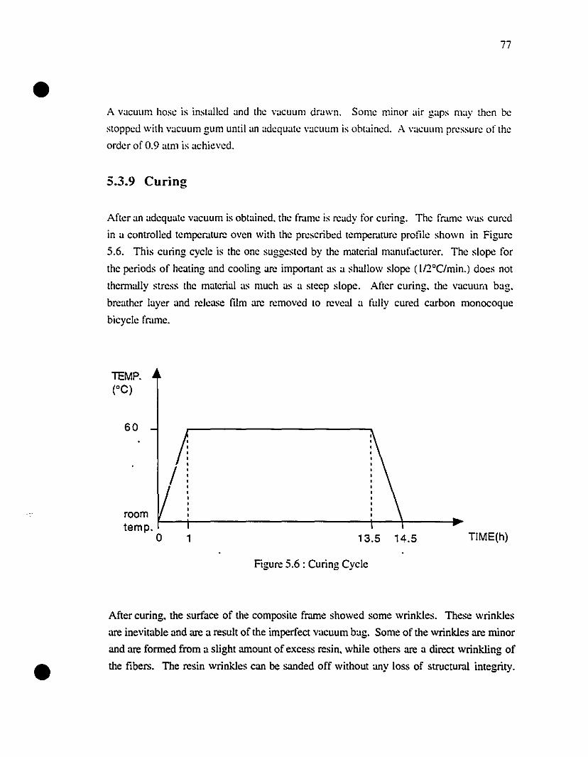
•77
A vacuum hose is installed and the vacuum dra\Vn. Some minor air gaps may then bc
stopped \Vith vacuum gum until an adequate vacuum is obtained. A vacuum pressure of the
order of 0.9 atm is achicved.
5.3.9 Curing
After an adequate vacuum is obtained. the fr.lme is ready for curing. The fmme \Vas cured
in a controlled temper.ltur:: oven with the prescribed temper.llure prolï1e shown in Figure
5.6. This curing cycle is the one suggested by the material manufacturer. The slope for
the periods of heating and cooling arc imponant as a shallow slope (112°C/min.) does not
thermally stress the material as much as a steep slope. After curing. the vacuum bag.
breather layer and release film arc removed 10 revcal a fully cured carbon monocoque
bicycle fmme.
60
roomtempo
o
/
1 13.5 14.5
Figure 5.6 : Curing Cycle
TIME(h)
•After curing, the surface of the composite frame showed sorne wrinkles. These wrinkles
arc inevitable and arc a result of the imperfect vacuum bag. Some of the wrinkles arc minor
and arc formed from a slight amount of excess resin, while others arc a direct wrinkling of
the fibers. The resin wrinkles can be sanded off without any loss of structura! integrity.
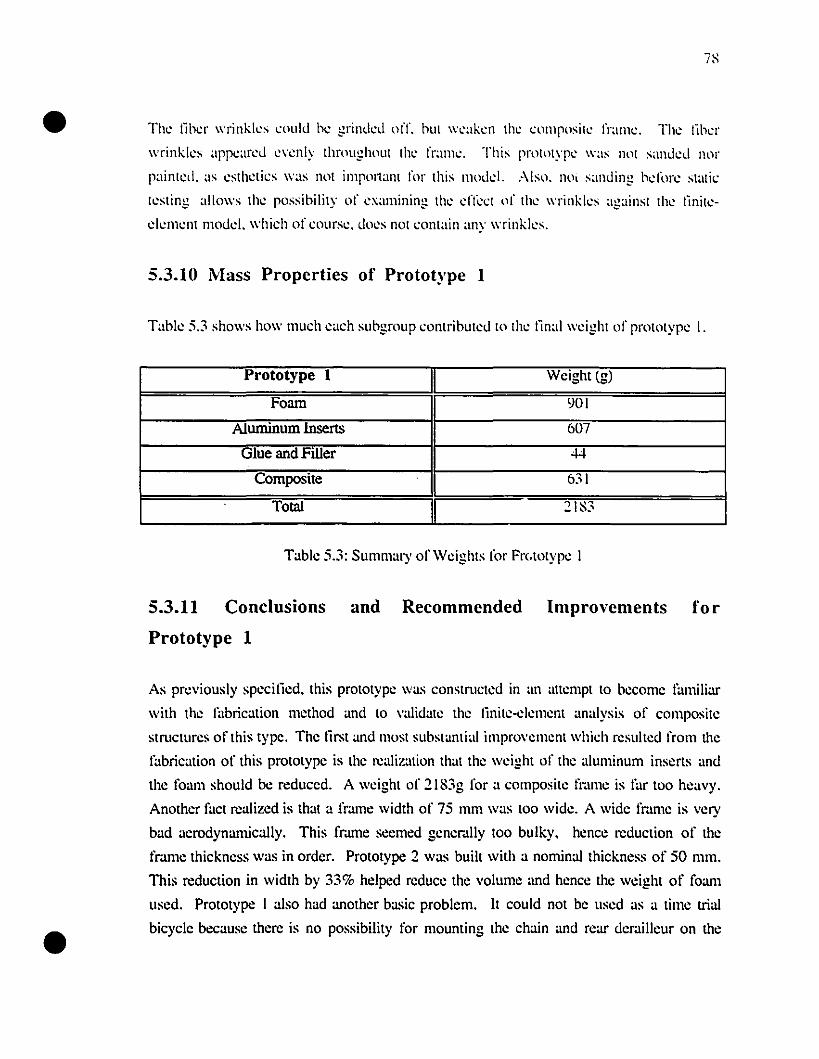
•ïS
The tiher wrinkks .:ould be grinded off. hUI weaken the <:llmposite frame. The lib.:r
wrinkles appeared e\'enly throughout the frame. This prolotype was not sanded nor
painled. :IS estheti.:s was not imp0l1am for this mode!. Aiso. no, sanding bd"ore stali.:
lesting allows the possihility of examining the dl\:<:l (lI' the wrinkles againsl the tinile
e!ement mode\. which of .:ourse. does nol .:ontain any wrinkles.
5.3.10 Mass Propcrties of Protot)'pe 1
Tahk 5.3 shows how much each suhgroup .:ontrihuted 10 lhe tinal \wight of protolype 1.
Prototype 1 Weight (g)
Foam 901
A1unùnum lnserts 607
Glue and Filler 44
Composite 631
TotaI 21S3
Table 5.3: Summary ofWcighls lor Frc.lOlype 1
5.3.11 Conclusions and Recommended Improvements for
•
Prototype 1
As pn:viously specitied. this prototype \Vas constructed in :1l1 allempt to beeome familiar
with the fabrication method and to v:llidate the tinite-e!ement analysis of composite
structures of this type. The lirst and must substantial improvement which resulted l'rom the
fabrication of this prototype is the realization that the \wight of the aluminum inserts and
the 10am should be reduced. A wcight of 2183g for a composite frame is far too heavy.
Another fact rcalized is that a fl'".lme \Vidth of 75 mm waS too \Vide. A \Vide fmme is very
bad aerodynamically. This fmme seemed genel'".ùly too bulky. hence rcduction of the
fmme thickness \Vas in order. Prototype 2 \Vas built \Vith a nominal thickness of 50 mm.
This reduction in \Vidth by 33% helped reduce the volume and hence the \Veight of foam
used. Prototype 1 also had another basic problem. Il could not be used as a time trial
bicycle because therc is no possibility lor mounting the chain and rear del'".lilleur on the
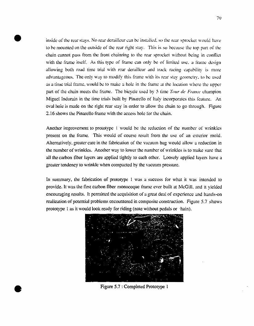
•
•
il)
insid.: of th.: r.:ar slays. No r.:ar d.:railkur can b.: instalkd. so lh.: war sprock.:t wou Il! h,m.:
10 b.: mounl.:d on th.: oulsid.: of lh.: r.:ar right stay. This is so b.:caus.: th.: 10p part of th.:
chain cannot pass l'rom th.: front chainring to th.: r.:ar sprock.:t without b.:ing in connict
with th.: fram.: ilS.:!!". As this lyp.: of fram.: can only hl: of limil.:d us.:. a fram.: d.:sign
allowing bath road tim.: trial with r':,lr d':l~lÎlkur and Irack racing capahility is mol'':
advantag.:ous. The only way ta modify this fram.: with its r.:ar stay g.:om.:try. to b.: us.:d
as a tilll': trial frame. would b.: 10 mak.: a hale in th.: fram.: al the location wh.:re the upp.:r
part of lhe ehain meets the frame. The bicycle used by :; time Tour de FraI/CC champion
Miguel Indurain in the time trials buill by Pinarello of haly incorporales this feature. An
oval holc is made on the right rear stay in order to allow the chain to go through. Figure
2.16 shows the Pinarello fmme with the access hole for the chain.
Another improvement to prototype 1 would be lhe reduction of lhe number of wrinkles
present on the frame. This wouId of course result l'rom the use of ,m eXlerior mold.
Alternativ.:!y. greater care in the fabrication of the vacuum bag \VouId allo\V a reduction in
the number of wrinkles. Another way to lower the numhl:r of wrinkks is ta make sure that
ail the carbon liber layers arc applied tighùy to each other. Loosely applied layers have a
greater tendency to wrinkle when compacted by the vacuum pressure.
In summary, the fabrication of prototype 1 was a success for what it \Vas intended to
provide. Il was the Iirst carbon liber monocoque fr.lme eyer built at ivIcGill. and it yielded
encour.lging results. It permilled the acquisition of a great deal of expcriencc and hands-on
realization of potenti.ll problems encountered in composite construction. Figure 5.7 shows
prototype 1 .IS it would look ready for riding (note without pedais or ·hain).
Figure 5.7 : Completc:d Prototype 1
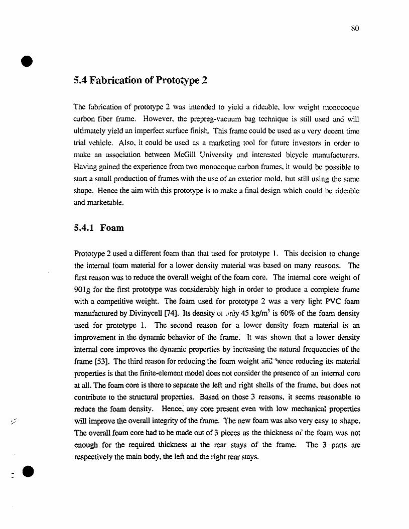
•
-.
so
5.4 Fabrication of Prototype 2
The fabrication of prototype 2 was intended to yield a rideable. low weight monocoque
carbon liber frame. However. the prepreg-vacuum bag technique is still used and will
ultimately yield an imperfect surface finish. This frame could he used as a very deccnt time
trial vehicle. Also. it could be used as a marketing tool for future investors in order to
make an association between McGill University and interested bicycle manufacturers.
Having gained the experience from two monocoque carbon frames. it would he possible to
stan a smaii production of fmmes with the use of an exterior mold. but still using the same
shape. Hence the aim with this prototype is to make a lina! design which couId he rideable
and marketable.
5.4.1 Foam
Prototype 2 used a different foam than that used for prototype 1. This decision to change
the internai loam materiai for a lower density materiai was based on many reasons. The
first reason was to reduce the overall weight of the foam core. The internai core weight of
90!g for the first prototype was considerab!y high in order to produce a complete frJ.me
with a competitive weight. The foam used for prototype 2 was a very Iight PVC foam
manufactured by Divinycell [74]. ILS density 01 .lnly 45 kg/m' is 60% of the foam density
uscd for prototype 1. The second reason for a lower density foam material is an
improvement in the dynamic behavior of the frame. !t was shown that a lower density
internai core improves the dynamic properties by increasing the naturJ.! frequencies of the
fr.une [53]. The third reason for reducing the foam weight ani::-'lence reducing il~ materiai
properties is that the finite-element mode! does not consider the presence of an internai core
at ail. The foam core is there to separate the !eft and right shells of the fr.une. but does not
contribute to the structura! pr0p"rties. Based on those 3 reasons. it seems reasonab!e to
reduce the foarn density. Hence; any core present even with low mechanical properties
will improve the overai! integrity of the frame. The new foarn was aIso very easy to shape.
The overai! foarn core had to he macle out of 3 pieces as the thickness oi the foarn was not
enough for the required thickness al the rear stays of the frame. The 3 parts are
respective!y the main body. the left and the right rear stays.
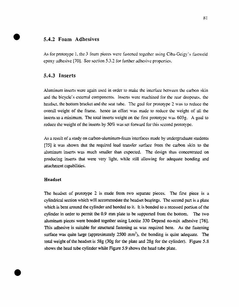
•
•
SI
5.4.2 Foam Adhesives
As for prototype 1. the 3 foam pieces \Vere fastened together using Ciba-Geigy's fastwcld
epoxy adhesi"e [70]. See section 5.3.2 for further adhesi"e properties.
5.4.3 Inserts
Aluminum inserts were again used in order to make the interface bctween the carbon skin
and the bicycle's extemal components. Inserts were machined for the rcar dropouts. the
headsct. the bottom br..lcket and the scat tube. The goal for prototype 2 was to rcduce the
ovemll wei"ht of the fmme. hence;m effort was made to rcùuce the wei"ht of all thee e
ins'~rts to a minimum. The total inserts weight on the tirst prototype \Vas 603g. A goal to
reduce the weight of the inserts by 50% was sel forward for this seeond prototype.
As a result of a study on carbon-aluminum-foanl intertàces made by undergr..lduate studenl~
[75] it was shown that the required load tr..lIlsfer surface l'rom the carbon skin to the
aluminum inserts was much smaller than expected. The design thus concentr..lted on
producing inserts that were very light. while still allowing for adequate bonding and
allachmcnt capabiliùes.
Headset
The headset of prototype 2 is made l'rom two sepamte pieces. The tirst piece is a
cylindrical section which will accommodate the headset ~ngs. The second part is a plate
which is bent around the cylinder and bonded to il. It is bonded to a recessed portion of the
cylinder in order to permit the 0.9 mm plate to be supported l'rom the bollom. The two
aluminum pieces were bonded together using Locùte 330 Depend no-mix adhesive [76].
This adhesive is suitable for structura! fastening as was required here. As the fastening
surface was quite large (approximately 2500 mm~). the bonding is quite adequate. The
total weight of the headset is 58g (30g for the plate and 28g for the cylinder). Figure 5.8
shows the head tube cylinder while Figure 5.9 shows the head tube plate.
•
31 dia. "
33 dIa.
I~30 dIa.
•,
'",~'Q, ,-,
•,,,,,,•••,,,,,,••,,
F,,,,
•
Figure 5.8: Head Tube Cylinder (all dimensions in mm)
1· "'----1I~_IF
Figure 5.9: Head Tube Plaie (all dimensions in mm)
Bottom Bracket
The bonom bracket is made of 3 pans. It contains the bonom bracket cylinder which gocs
through the frame and one plate recessed in the foum on both sides of the fr.une in order to
secure the cylinder in place. The bonom bracket cylinder is intemally threaded with a
1.370X24 Ieft handed thread at one extremity and a right handed thread at the other
(standard procedure). These threads were cut in order to mect with the bottom bracket
cartridge pedal case. Both bonom bracket plates recessed in the foum were_bonded to the
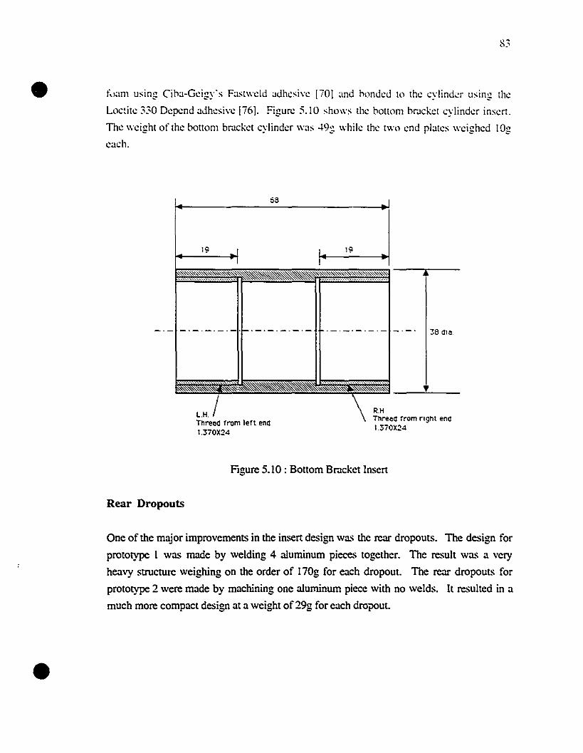
•-"ü."'I
t~,am using Ciha-Geigy's Fast\\'cld adhesi\"e liO] :md honded to the cylind~r lIsing the
Loctite 330 Depend adhesi\"e [i6]. Figure 5.10 shows the honom hrackel cylinder insen.
The \\'eight of the bonom bracket cylinder \\'as 49g \\'hile the t\\'o end plates \\'eighed lOg
each.
68
19 19
~I
38 dle
L.H. /Thread fram lert end1.370X24
R.HThreca from nght end1.370X24
•
Figure 5.10 : BOllOm Bracket Inser!
Rear Dropouts
One of the major improvements in the inscr! design was the rear dropouts. The design for
prototype 1 was made by welding 4 a1uminum pieces together. The result was a very
hcavy structure weighing on the order of 170g for cach dropout. The rear dropouts for
prototype 2 were made by machining one a1uminum piece with no welds. It resulted in a
much more compact design at a weight of 29g for cach dropout.
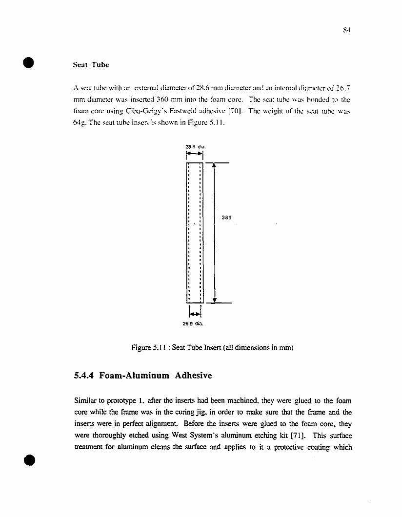
•
•
Scat Tube
A s~at tube with an ~xt~rnal diam~l~r of 28.6 mm diam~t~r anG an inl~rnal diam~t~r of 26.7
mm diam~t~r was ins~rt~d :;60 mm inlo Ih~ foam cor~. Th~ s~at tube was h()nd~d 1<' th~
foam corc using Ciha-G~igy's Fastwcld adh~si\'c 170J. Th~ wcight of th~ scal tubc was
Mg. Th~ s~al tuh~ inscr, is shown in Figur~ 5.11.
28.6 dl.J.
H-,--
389
!
26.9 dia.
Figure 5.1 1 : Seat Tube Insert (ail dimensions in mm)
5.4.4 Foam-Aluminum Adhesive
Similar 10 prototype I. after the inserts had been machined, they \Vere glued to the foam
core while the frame was in the curing jig. in order to make sure that the frame and the
inserts were in perfect aIignment. Before the inserts were gIued to the foam core, they
were thoroughly etched using West System's aIuminum etching kit [71]. This surface
treatment for aIuminum cIeans the surface and applies to it a protective coating which
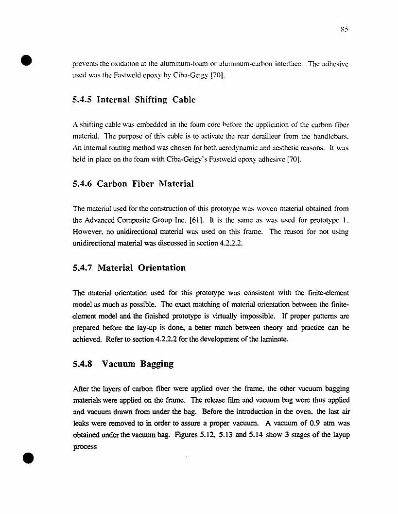
•
•
prevents the oxidation at the aluminum-foam or aluminum-carhon interface. The adhesive
used \Vas the Fast\Vcld epoxy hy Ciha-Geigy [iO].
5.4.5 Internai Shifting Cable
A shifting cable \Vas embedded in the foam core hdore the application of the carbon liber
materiaJ. The pUI-pose of this cable is to aetivate the rear der.lilleur from the handlcbars.
An internaI routing method \Vas chosen for both aerojynamie and aesthetic reasons. It \Vas
hcld in place on the foam \Vith Ciba-Gcigy's Fas!wcld cpoxy adhcsive [iO].
5.4.6 Carbon Fiber Material
The materiaJ uscd for the construction of this prototype \Vas \Voven materiaJ obtaincd from
the Advanced Composite Group Inc. [611. It is the same as \Vas uscd for prototype 1.
However. no unidircctionaJ materiaJ was used on this fmme. The rcason for not using
unidircctionaJ materiaJ was discussed in section 4.2.2.2.
5.4.7 Material Orientation
The materiaJ orientation used for this prototype was consistent with the linite-elemem
model as mueh as possible. The exaet matehing of materiaJ orientation betwcen the finite
clement model and the fiaished prototype is viltuaJly impossible. If proper patterns arc
preparcd before the lay-up is done. a better mateh between theory and pmetice ean be
aehieved. Refer to seetion 4.2.2.2 for the development of the laminate.
5.4.8 Vacuum Bagging
After the layers of earbon fiber were applied over the fmme. the other vaeuum bagging
materiaJs were applied on the frame. The release film and vaeuum bag were thus applied
and vacuum dmwn from under the bag. Before the introduction in the oven. the last air
leaks were removed to in order to assure a proper vacuum. A vacuum of 0.9 atm was
obtained under the vacuum bag. Figures 5.12. 5.13 and 5.14 show 3 stages of the layup
process
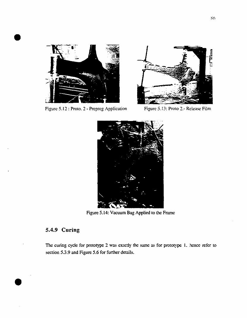
•
Figure 5.12 : Proto. 2 - Prepreg Application Figure 5.13: Proto 2.- Release Film
•
,-Figure 5.14: Vacuum Bag Applied to the Frame
5.4.9 Curing
The curing cycle for prototype 2 \Vas exactly the saIlle as for prototype 1. hence refer to
section 5.3.9 and Figure 5.6 for further details.
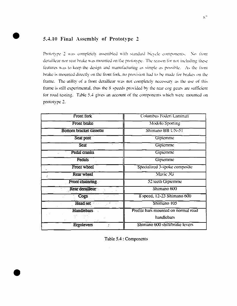
•
•
SA.IO Final :\sscmbl~' of Protot~·pc 1
Pn't~'IYI'1: .:. \\~I;-' cnmrk~tdy assc.:l1lbkd \\,jlh sland~ll\l bi ..... y,,:k I..·\lmplltll.:nh. 'l) l'l\)fl!
dcraillcur nor n:ar hrakc.: was mULlr1tc.:d on t!l(' rnHlltypc.:. Th~' rc.:~I;--I)J1 fl)r Ih'i il1l."ludin.:= tilc.:;..l..~
fc.:~ltlln:s \\'as to kc.:c.:p thl.: dc.:sign and Il1~lIlll(a('tllrin~ ~IS .... imph: a;-. possihk. :\" thl..' frnnl
hrake is mounted direetly on the front fork. no pn1\j,il1l1 had to be made fllr hrakes lm th,'
l'raille. The utility of a front derailleur \\'as not eomplctdy neee"ary as the use of this
frame is still experimentaI. thus the S speeds pro\'ided hy the rear eng gears arc suflieient
for road testing. Tahle 5.4 gi\'cs an accollnt of the comron~nts whil.:h wcre mOllntcd on
prototype 2.
Front fock Columhus Foderi Lalllinati
Front brake "Ioclolo Sporting
Bottom bracket cassette Shimano BB U1':·5 1
Searpost Gipielllmc
Sear Gipicmmc
Pedal cranks GipiClllmc
Pedals Gipicl111IlC
Frontwheel Spccializcd 3·spokc composite-
Rearwheel Ma\'ie 3G-Front chainring . 52 tccth Gipicmmc
Rear derailleur: .. Shimano 600. '. . .,
cogs 8 spccd. 12-23 Shimano 600
Headset .' . , . Shimano 105
Handlebars Prolllc bars mountcd on norm.ll road
handlcbars
Ergolevers : Shimano 600 shiftlbr.lkc Ic\'crs
Table 5.4 : Componcnts
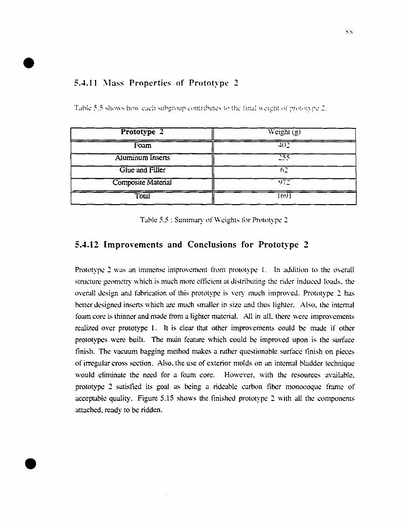
•
•
SA. 11 \lass Propcrtics nI' Prntot~pc ~
Prototype 2 Weight(gl
Foam .+02
A1uminum lnsens 255
Glue and Filler 62
Composite Matena! LJï2
Total 1691
T~olc 5.5 : SUlllm~ry of Weight, for Prototype :::
5.4.12 Impro\'ements and Conclusions for Protot~·pc .,
Prototype ::: w~, ~n imlllen,e impro"ement l'rom prototype 1. ln ~ddition to the o\.er.lll
,trueturc geometry whieh i, lllueh more eftieient :ll di,triouting the rider induccd lo~d,. the
o"erall de,ign ~nd f~orieation of thi, prototype i, "ery lllueh irnpro"ed. Prototype::: h:l'
hetter designed inserts whieh arc mueh smaller in size and thu, lighter. Abo. the internai
fo~m core i, thinner ~nd made l'rom a lighter material. .-\11 in ail. there were impro"ements
rcalized o"er prototype 1. It is dear that other impro"ements eould he made if other
prototypes were buill. The main feature which could he impro"ed upon is the surfacc
linish. The vacuum bagging method makes a r.lther question:lble surfüce tinish on pieccs
of irrcgular cross section . .-\lso. the use of exterior molds on :m internai bladder technique
would c1iminate the necd for a foam core. Howe"er. with the resources ~vailablc.
prototype 2 satislied its goal as heing a rideablc carbon liher monocoque fr.ll11e of
acceptable quality. Figure S.IS shows the linished prototype::: with ail the eomponents
attached. ready to be ridden.
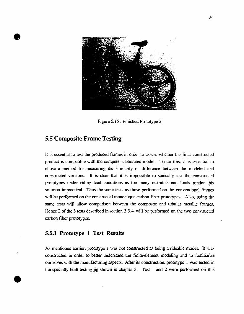
•
•
Figure 5.15: Finished Prototype 2
5.5 Composite Frame Testing
It is essential tO test the produced fmmes in order to assess whether the tinal constructed
product is compaùble with the computer clabor.lled mode!. To do this. it is essential to
chose a meth,xl for measuring the similarity or differencc bctween the modcled and
constructed versions. It is c1car that it is impossible to statically test the constructed
prototypes under riding load condiùons as too many restraints and loads render this
solution impractical. Thus the same tests as those performed on the conventional fr.tmes
will be performed on the constructed monocoque carbon liber prototypes. A.iso. using the
same tests will a1low comparison between the composite and tubular metallic fr.rmes.
Hence 2 of the 3 tests describt.'d in section 3.3.4 will he performed on the two constructed
carbon liber prototypes.
5.5.1 Prototype 1 Test ResuUs
As menùoned earlier. prototype 1 was not constructed as being a ridcable mode!. It was
constructed in order to better understand the finite-element modeling and to familiarize
ourselves with the manufacturing aspects. After its construcùon. prototype 1 was tested in
the specially built tesùng jig shown in chapter 3. Test l and 2 were performed on this
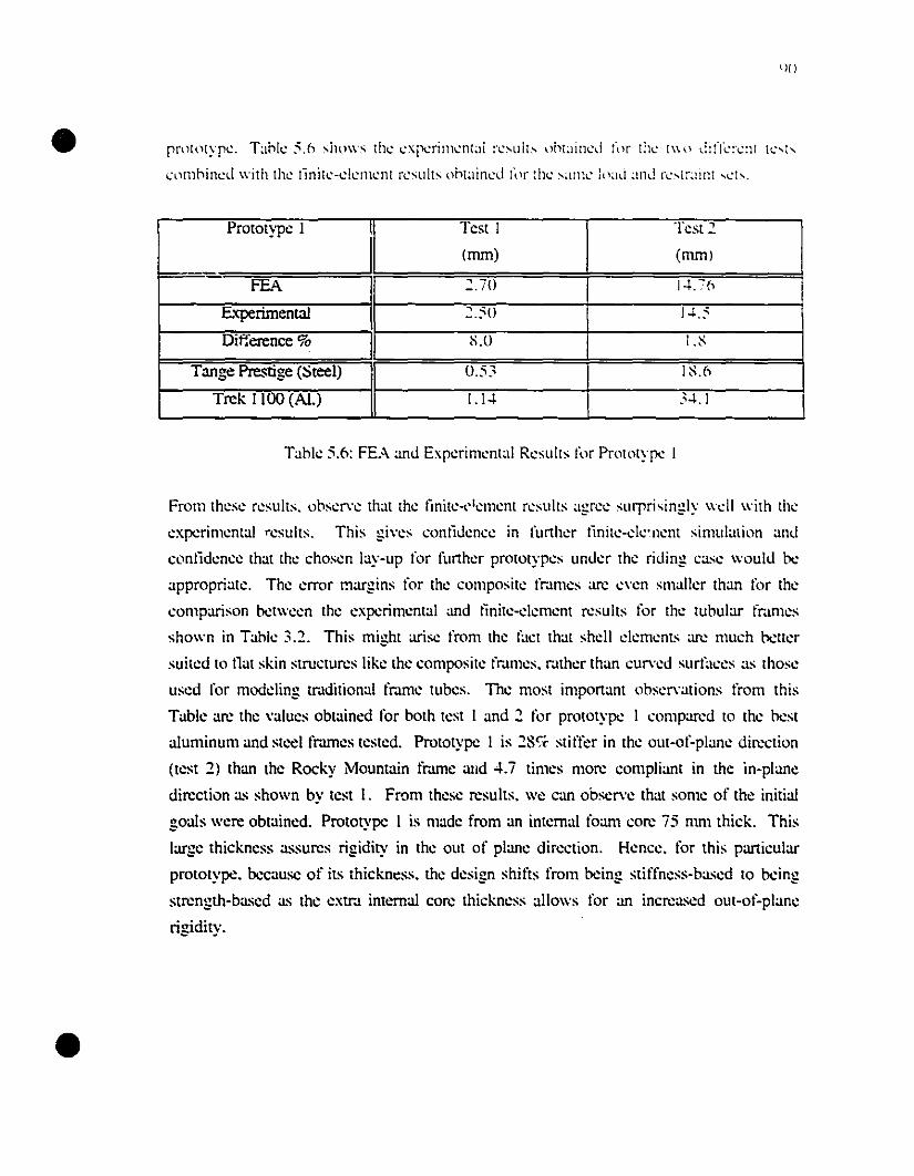
•
•
pnHolypl.:. Tahle :'.6 shows the.: c.::xreril1lc.:n{~d n:~Lllt~ l)ht~lirH.:d (Ill" IhL' 1\\\.) diIIL'!\:nt h.· ... r...
l"."nmhinc.:d with the.: lïnitc-dellll.:nl n.:sults nht~lincd 1'1.)1' :hL' ~~lllll..· ll.lad and rL· ... {r~1l111 ,ch.
Prototype 1 Test 1 Test 2
1
(mm) (mm)
FEA 2.70 1"+. :6
Experirnent:ll 2.50 1..1,:'
Difference % S.O I.S.
Tange Prestige (Steel) 0.53 1S.n
Trek 1100 (AI.) 1.1 .. 3... 1
Tahle 5.6: FEA :md Experimcntal RcsullS for Prototype 1
From thesc results. ohscr\"c that thc linitc...·1clllcnt results agrcc surprisingly wcll \\'ilh thc
cxperimcntal rcsults. This gi\"cs contidencc in furthcr tinitc-c1c'nent simulation and
eontidencc that the ehosen lay-up for further prototypes under the riding case would he
appropriate. The error margins for the compositc frJ.mes arc e\"en smaller than for the
comparison hetween the experimental and linite-c1ement results for the tuhular frJ.mes
shown in Tahle 3.2. This might arise from the fuel that shell clements arc much hetler
suited to nat skin structures like the composile frJ.mes. rJ.ther than curved surfaccs as those
used for modcling trJ.ditional frJ.nle tubes. The most important obser,ations from this
Table arc the \"alues obtained for both test 1 and 2 for prototype 1 comparcd tO the hest
aluminum and stec! fmmes tested. Prototype 1 is 28,/" stifter in the out-ol~plane direction
(test 2) than the Rocky Mountain fmme :lIld 4.7 times more compliant in the in-plane
direction as shown by test 1. From these results. we can obser\"e that some of the initial
goals were obtained. Prototype 1 is made from an internaI foam core 75 mm thick. This
large thickness assures rigidity in the out of plane direction. Hence. for this particular
prototype. bccause of ils thickness. the design shifts from bcing stiffness-based to bcing
strength-based as the eX!rJ. internal core thickness allows for an increased out-of-plane
rigidity.
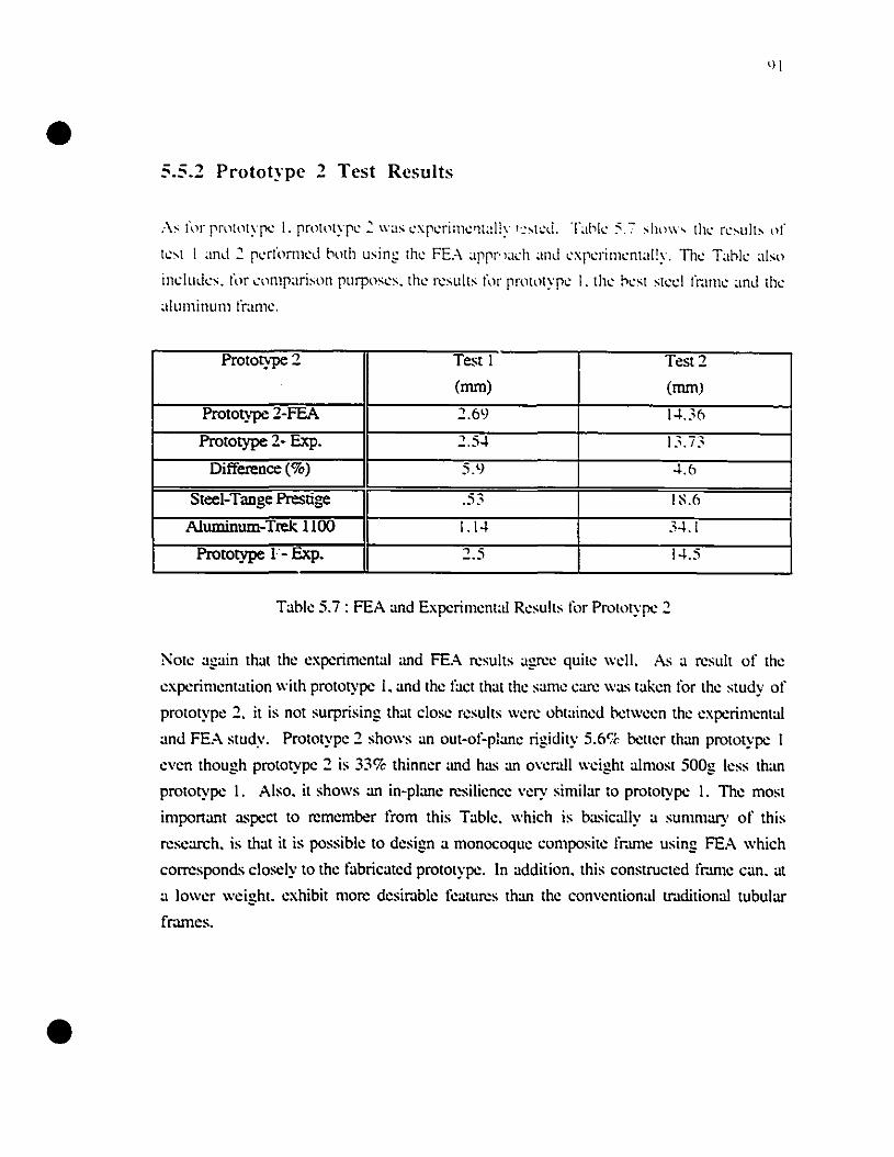
•
•
5.5.2 Prototype ., Test ResuIts
..\s fnr pnltnlyp~ 1. prnl')lyp~: \\'as ~xp~rilll~'1tally I·:,t~d. Tahk ~.7 ,Ihl\\" Ih~ r~'lIlb nI'
l~'l 1 and : p~rfnrlll~d hnlh lIsinl; Ih~ FE.-\ appr"adl and ~xl'~rilll~nt;li!y. Th~ Tank alsn
indlllks_ f,'r ~nmparisnn 1'1Irpns~s. Ih~ r~slliis fnr pl\ll,ltyp~ 1. Ih~ n~sl sl~d fr;lll1~ ;md Ih~
;llul11inlllll fralll~.
Prototype 2 Test 1 Test 2
(mm) (mm)
Prototype 2-FEA 2.69 1... 36
Prototype 2- Exp. 2.5.. 13.ï3
Difference (%) 5.9 ... 6
Steel-Tange Prestige .53 1~.6
Aluminum-Trek. 1100 1.1 .. 3... 1
Prototype 1- Exp. 2.5 1...5
Tablc: 5.7 : FEA and Experim~ntal R~sults fôr Prototype 2
Note al;ain that the experimental and FEA results agree quite \\'dl. As a result of the
experil11entation \\'ith prototype 1. and the factthat the same eare \Vas taken for th~ study of
prototype 2. it is not surprising that close results \Vere obtained bet\Veen the experimental
and FEA study. Prototype:2 shows an out-ol'-plane rigidity 5.6'1" better than prototype 1
even though prototype 2 is 33% thinner and has an ovemll weight almost SOOg less than
prototype 1. Also. it shows an in-plane resiliencc very sil11ilar ta prototype 1. The most
important aspect ta rcmember l'rom this Tablc:. which is basically a summary of this
research. is that it is possible ta design a monocoque composite fr.une using FEA which
corresponds closely to the fabricated prototype. ln addition. this constructed thune cano at
a 10\Ver weight. exhibit more desir.lble features than the conventional tr.lditional tubular
frames.
•
•
5.6Summary
Th.: tirst pan of this chapt.:r has shown th.: proc.:Jur.: for rh.: construction of rh.: two
carbon lib.:r monocoqu.: fram.:s. Altho...gh th.: fabrication proc.:Jur.: chos.:n CllulJ only
apply to th.: construction of prototyp.:s. it has show;) 10 h.: v.:ry appropriat.: for this
purpos.:. Th.: w.:ight and surfac.: tinish of both prototyp.:s coulJ b.: improv.:J with th.: us.:
of anoth.:r production m.:thod. Lising another production m.:thod. such as an int.:mal
bladder technique. couid rcdu:.: th.: w.:ight of th.: frJ.m.:s to th.: rJ.ng.: of th.: lightest on th.:
mark.:t (1.2kg) while stil! showing .:xcdI.:nt stiffn.:ss attribut.:s comparcd to oth.:r light
frJ.mes which arc usually .:xtrcmcly tlexible.
Th.: s.:cond pan of chapter 5 was concemed with the testing of th.: fabricated frames and
comparison with metallic tubular frJ.mes tested under the same conditions using the sanle
apparatus. The rcsults have shown the composite frJ.mes to he stifter in the out-of-plane
direction and more resilient in the in-plane din.'Cùon. two attributes which arc beneficial for
a bicycle frame. It is thus encouraging to observe that the iniùal goal set forth has bt:en
met: to produce a carbon fiher monocoque frJ.me with dircctional!y tailorcd properties.
•
•
Chapter 6
Conclusion
The methodology for designing composite bicycle fr.lmes illustmtcs the importance of
using tinite-clement analysis as a way of minimizing the cost and time required for different
designs. The analysis can be effective for determining both geometry and tanùnale design
to oblain bener strength and stiffness char.lcleristics lhan tmditional tubutar franles. The
thrce carbon tiber monocoque fr.lffie designs presented are a resutt oi this design process.
From lhese designs. il is evident that a carbon tiber fr.ll11e shoutd be buitt using many
differenl laminates which correspond to the different stress regions as the goat shoutd be to
have a structure with a uniform stress tevelthroughout. The addition of local reinforcement
has been shown to reduce local stresses. Local reinforcement can be added to the fr.lffie
with a minimum increase in overJ1l \wight.
Finite-element analysis wa.~ also used to numerically compute fr.lffie stiffnesses in order to
compare with experimental resull~ performed on tubular and composite ti-.lmes. Fr.lffie
stiffness is important when atlempting to design the fr.lffie for performance and rider
comfort. When discussing the stiffness of fr.lffies, it is actualty the directional stiffness that
the designer should he concemed \Vith as torsional stiffness is desir.lble white in-plane
stiffness is not. While frame stiffness is inherently involved in the process, it is the
intemction of the biomechanical characreristics of the individual rider with the bicycle that
ultirnately determines whemer me bicycle has a feel mat is too "sofe or too "stiff'.
Detennination of how me quantifiable fr.lffie stiffness characteristics relate to me qualitative
description of what me rider senses is an important factor to consider funher. It has been
successfuIly shown mat wim simple tests, different important franle stiffnesses can he
measured and can he used to quantify me quality of different fr.lffies.
•
•
The rrdin1il1~u'Y static tl.:stlI1:; t)f [r~lliitll)Jlal fr~lIl1l'''' \\ ~l' ~·"""'l·t1tial Il' t!ll'" r~"'l'~lI\,:h ~t ... H
p~rmill~Ù th~ ù~\dopm~nt ol'Ih~ I~slin~ !11~lho,b \\ hich \\ "llid he' lls~d f<'r lh~ c"rhon lihe:r
prolotyp~s holh ~xrc:rilll~nt"lIy and l1l111l~ri~ally. Th~ traJillon,d fralll~' pr<,dllc~J r~'1I1"
whkh w~r~ f<'lInJ {(l he invalll"hk for ~"mp"rison wilh Ih~ C<'!l'lru~I~J carhon lih~r
protolyp~s. "h a r~sllii ,,l' Ihis I~stin~. il wa, ,hown Ih"l th~ ,"ll1,lrllCI~d carhon nhe:r
rram~s sho\\~d slifrn~" "llrihlll~s whidl \\~r~ ck"rly 'lIp~rior 10 Ih~ he:sl tradilional fr:lIll~'
~xamin~d, It is illlport"nt l" not~ Ih,'1 Ih" illlrrll\~m~l1l \\,,, pr~dict~d \\'jlh Ih~ fll1jl~
dClncnt ana.!ysis l..:'\"cn hcfon: the- tirst L'arhl..Hl lïlx-r framl~ W~l;-. l'\..l(1"tnll.:tl:d.
Th~ ,~cond pan or this r~s~","~h \\"S th~ J~\dOplll~nl of " mal1l1l'''~tllrin~ l~chniqll~ for
~omposit~ mat~ria! hicyde frames, The melhoJ ~hosen provideJ. al 10\\ ~osts. lh~ most
llexihk means of prodll~ingprototypes, The hanJ laynp of prepreg ~arh,)n1epoxy materia!
to an internaI roam eore \\as iJeal l'or pmtotyrc: moJding, The main inconwniences ",hich
resulted l'rom this method arc the linal sllrrac~ linish. \\hich is de","ly inappropriate l'or a
m","ketahlc produel. and the impossihility or removing the Internai core alkr curing, ln a
prodllction situation. it \\ould he: ess<:mia! to remove Ihe interna! core sincc in the
prototypes il contributes 25 to 40,;' or the timshed rr.une \\eighl. Prototype 1 achi~wJ its
goal or ocing a tria! prototype l'or th~ linit~-clcm~nt m~thod. rabrication method and to
devclop the testing procedures. Prototype 2 also matched its goal or being a rideable and
adequate pre-production prototype.
ln addition to ils high strength and stirrness propenies. it is the versatility or carbon liber
which makes it an excellent materia! l'or lightweight structures, Bicyde rr.lmes arc an
excellent exanlple or successrul application ûr this material.
•
•
95
Chapter 7
Recommended Further Research
As future and complementary research. several other aspects of composite bicycle design
should he exarnined in order to obtain a complete slUdy. With respect to the finite-element
modeling. it would he interesùng to model the frame using solid elemenL~ for the internai
core. A more detailed analysis could be perforrned on the metal/composite interfaces at the
joint locations. This could include considerJùon of titanium as a more compatible material
for use as insens. Also. in addition to the use of reinforcement. geometric redesign of
cenain regions should he considered in order to reduce the stresses to a minimum. Both
finite-element and experimental dynarnic loading should he perforrned in order to assure the
structural integrity. for example. due to high rate impact. Experimental fatigue testing
should he perforrned on the frames in order to assure long terrn structural integrity even
though carbon fiher is known to have excellent fatigue resistance. The complete series of
standards bicycle tests should he imposed on the prototypes in order to assure that the
production models would respect those standards.
This study was focused on the bicycle frame structural design. but aerodynarnie testing
should he perforrned in order to reduee the frame drag. Minute changes to structural cross
sections may produce a huge reduction in aerodynarnic drag.
•
•
96
Further research and work on the fabrication method ta he used should be performed.
Bath the fabrication method of the prototypes and the fabrication method for large scale
production should be further examined. An appropriate. la\\' cast moulding procedure
should be devised.
Last but not least. therc is a potential for further rcsearch in non-conventionnai composite
fr.lme building materials. It seems that a thermoplastic matrix combined with new libers
such as Vectr.ln or Dynema could potentially rcvolutionize fr.ulle building. both in tl:e
quality of the products and in the marketing appeal which would emanate l'rom the use of
these new materials.
Different geometries and loading cases could also he e1abor.lted for differcnt types of uses
such as mountain biking. triathlon. olympic pursuit and even touring.
Analysis of the complete f=e as part of a complete dynamic system comprising of aIl
other components such as the front fork and wheels. A study of this type would l'ully
chamcterize the response of a f=e in a realistic situation with the intemction of all the
componenL~ .
•97
Publications Resulting from this Work
A) Patrick L. Lizone. Larry B. Lessard. James A. Nemes. "Design of Ad\'anced
Bicycle Frames". ATMAM 1994. Montreal. August 10-12 1994. pp. 90-97.
•
B) Larry B. Lessard. James A.Nemes. Patrick L.Lizone. "Utilization of FEA in the
Design of Composite Bicycle Frames", Composites, Vol 26, Number 1. pp Î2-
74, 1995.
C) Patrick L. Lizone, Larry B. Lessard, James A. Nemes, "Stress and Failurc
Ana1ysis ofComposite Bicycle Frames",\CCM-10, Whistler s.e., August \4-18
1995, Vol.lII, pages 70 \-708 .
•
•
9S
References
1- Perry. D.B.. Bike Cul!, Four Walls Eight Windows. New·York and London. 1995.
2- Rowland. F.W.. and Wilson, D.G..Bicvcling Science. Second Edition. MIT Press.
Cambridge Massachusetts. 1982. p. 6.
3- Rowland. F.W.. and Wilson. D.G .. Bicvcling Scicnce. Second Edition. MIT Press.
Cambridge Massachusetts. 1982. p. 9.
4- Rowland. F.W.. and Wilson. D.G.. Bicvcling Science. Second Edition. MIT Press.
Cambridge Massachusetts. 1982. p. 14.
5- Rowland. F.W.. and Wilson. D.G.. Bicvcling Science. Second Edition. MIT Press.
Cambridge Massachusetts, 1982, p. 19.
6- Rowland, F.W.. and Wilson. D.G.. Bicvcling Science. Second Edition. MIT Press.
Cambridge Massachusetts. 1982. p. 20.
7- Rowland. F.W.. and Wilson. D.G.. Bicvcling Science. Second Edition. MIT Press.
Cambridge Massachusetts. 1982. p. 259.
8- Kukoda. 1., "Steel". Bicycling, August 1993. pp. 80-83.
9- Editors of Mountain Bike and Bicycling Magazine. Bicvcling Magazine Complete Guide
to Bicvcle Maintenance and Repair. Rodale Press. Emmaus. Pennsylvania. 1994.
p.14.
10- Editors of Mountain Bike and Bieycling Magazine. Bicvcling Magazine Complete
Guide to Bievcle Maintenance and Repair. Rodale Press. Emmaus. Pennsylvania,
1994, p.16.
11- Rowland, F.W.. and Wilson, D.G.. Bicvcling Science. Second Edition, MIT Press.
Cambridge Massachusetts. 1982. p. 262.
12- Kukoda, J.. 'Tubing Tutorial", Bicycling. 1991. pp. 120-123.
13- Kukoda, 1., "Titanium: The Miracle Metal". Bicycling. July 1989, pp. 110·114.
14- Kukoda, J.. "Titanium", Mounrain Bike, November 1990, pp. 5-7.
15- Lessard, L.B.. Composite Materials Class Notes, McGill University. 1993. p. 4.
16· Rowland. F.W.. and Wilson, D.G.. Bicvcling Science. Second Edition, MIT Press,
Cambridge Massachusetts. 1982. p. 244.
17· Gould, R., "The Bike Built to Win", New Scienrisr. June 30 1990. pp. 49-5 I.
18- Kukoda, J.. "Materials Update", Bicycling, May 1988, pp. 90-96.
19- Huit. J., 'The Itera Plastic Bicycle". Social Srudies afScience. 22,1992. pp. 373
385.
•
•
99
20- Mallick. P.K.. Fihcr Reinforced Composites. Second Edition. Marcel Dekker Inc.
New-York. 1993.
21- Roosa. D.. "A Taste of the Future". Bicycle Guide. August 1987. pp. 20-29.
22- "The 1994 Guide to Carbon Fiber Bikes". MOll1lrain Bike Acrion. April 1994. pp. 44.
23- Lai. G.. "Aegis". Bicycle Guide. November 1994. pp. 34-37.
24- Gruenwedel. E.. "Truly World Class". lVilllling. 1992. Fp. 62-63.
25- Barnell. 1.. "Carbon Fiber: Is the Future Here". Cyclisr. September 1994. pp.26-29.
26- Kestrel 1991 Pre-Saison Dealer Catalog. 1991.
27- Trirnble. BJ.. Bicycle Frame. U.S. Patent #4.513.986. April 30 1985.
28- Trimble. BJ.. Bicycle Frame. U.S. Patent # Re 33.295. August 14 1990.
29- Trimble. BJ.. Composire Bicycle Frames and Merhods ofMaking Same. U.S.
Patent # 4.889.355. December 26 1989.
30- Trimble. B.J.. Tubular Bicycle Frame. U.S. Patent # 4.941.674. July 17 1990.
31- Roosa. D.. "Graphite Technology Racingbik". Bicycle Guide. April 1990. pp. 82
84.
32- Kim. I.. "Racers. Rough Riders and Recumbents". Meclwnical Engineering. May
1990. pp. 52-59.
33- Riedy. M.• "Corima Road". Bicycle Guide. November 94. pp. 22-26.
34- Zinn. L.. "Boardman's World Hour Record Bike". Velonews. August 30 1993.
p.22.
35- "Zipp 2001 Road Bike". Raad Bike Acrion, November 93. pp. 13-19.
36- "Lemond". Winning. January-February 1994. p. 23.
37- Lai. G.. "Bearn Bikes", Bicycle Guide. Seplember 1994. pp. 29-36.
38- "Mike Burrough's Red Giant", Bicycle Guide, November 94. pp. 17-18.
39- Associaled Press, "Indurain Sets Record for Distance in Hour", Montreal Gazette.
Saturday September 3 1994.
40- Guiness. R., "Indurain Breaks 53km Hour Record Barrier", Velonews, October 3
1994. p. 21.
41- Whittle, J., "The Final Frontier", Winning. November 94, pp. 66-69
42- Vroomen, G., "Design of an Aerodynamic Time Trial Bicycle", Final Ycar
Project, Eindhoven University ofTechnology, The Netherlands, 1995.
43- "Hotta Time Trial Champ", Raad Bike Action, March 1995, pp. 56-61.
44- Bolourchi. F., Hull, M.L., "Bicycle Frame Stress by Means of Finite Element
Analysis", ASME DES. ENG. DIV. PUBL. DE., VoU 1. 61-72. 1987.
45- Redcay, J., "CAD Cornes to Cycling", Bicycling Science, April, 105-115. 1986.
•
•
100
46- Peterson. L.A.. Londry. K.J .. "Finite Element Structural Analysis: a Ne", Tooi for
Bicycle Frame Design". Bike Tech. Vo!.5. No.2. 1-9. 1986.
47- Lizone. P.L.. Lessard. L.B.. Nemes. J.A.. "Design of Ad\'anced Bicycle Frames".
ATJHAM 1994. Montreal August 10-12. 1994.
48- Da\'is. R.R.. Hull. M.L.. "Design of Aluminum Bicycle Frames". lourna! of
Mec1wnica! Design. \'01.1 03 noA. 901-907.
49- ISO 4210 Bicycle Standard. Organisation Internationale de Normalisation. Gene\'a.
Switzerland. 1993.
50- JSA 9401 Bicycle Standard. FrJ.me-Fork Assembly for Bicycles. lapanese Standards
Association. Tokyo. Japan. 1995.
51- Comminee for Bicvcling Standards. ASTM (American Societv for Testing and. - .-Materials). Philadelphia. PA. established 1995.
52- Flanagan. T.M.. Dyer. R.M.. "Composite Monocoque Bicycle". 38th Internationa!
SAMPE Symposium. Anaheim Ca!ifornia. May 10-13 1993. pp. 293-305.
53- Castejon. L.. ct al.. "Composite Monocoque FrJ.me for a Mountain Bicycle: Testing
and Calculations". Applied Composite Mcueria!s. 1. pp. 247-258. 1994.
54- Macmartin. 8.. "Carbon Fiber Monocoque Frame Design for Mountain Bikes".
Bulletin d1nformation. CACSMA. Vol. 7. no.l. March 1994. p. 4.
55- Eckold. G.. Design and Manufacture of Composite Structures. McGmw-Hill Inc..
New-York. 1994. p.268.
56- SDRC I-DEAS version 6. IntegrJ.ded Design Engineering Software. user manual.
Structural Dynamics Research Corporation. Milford. OH. 1991.
57- Roy. M.• Chabot. G.. and Lavin. A.• "Bicycle Frame Testing Jig". Design 3 Final
Report. McGill University. 1994.
58- SDRC I-DEAS version 6. Integraded Design Engineering Software. user manual.
Structural Dynarnics Research Corporation. Milford. OH. 1991.
59- Devallée. R.. and Tizi. J-P.. "Conception et Calcul de Structure d'un Velo en
Matériaux Composite". Projet de Fin d·étude. Ecole National d1ngénieurs de MelZ.
France. Juin 1993.
60- Union Cycliste International. Rule 49. May 1994.
'61- The Advanced Composite Group. Technical Manual. Tulsa. Ok. 1994.
62- Hull. M.L.. Bolourchi. F.. "Contribution of Rider Induced Loads to Bicycle Frame
Stress". ASME DES. ENG. DIV. PUBL DE.• voL!. 25-28. 1986.
63- "Pour la Science". February 1984. pp. 69-72
•
•
101
64- Rowland. F.W.. and Wilson. D.G.. Bicycling Science. Second Edition. MIT Press.
Cambridge Massachusetts. 1982. p. 281.
65- Rowland. F.W.. and Wilson. D.G.. BicYcling Science. Second Edition. MIT Press.
Cambridge Massachusetts. 1982. p. 3ï.
66- Rowland. F.W.. and Wilson. D.G.. BieYcling Science. Second Edition. MIT Press.
Cambridge Massachusetts. 1982. p. 52.
6ï- Rowland. F.W.. and Wilson. D.G.. Bicvcling Science. Second Edition. MIT Press.
Cambridge Massachusetts. 1982. p. 46.
68- Tsai. S.W.. and Hahn. H.T.. "Introduction to Composite Materials". Technomic.
1980._
69- Dufresne. S.. Godin. S.. Munger. S.. ··Analysis. Testing and Sampling of a
Composite Bicycle Frame". Meehanical Laboratory II Final Report. MeGilI
University.ApriI1993.
ïO- Formulated Systems Group. Ciba-Geigy Corporation. Araldite Fastweld Adhesive.
East Lansing. Mi.
71- Gougeon Brothers Inc. 1994 West System Technical Manual. 860-8 Aluminum
Etching Kit. Bay City. Mi.. 1994.
ï2- Grégoire. S.• Jones. A.• Kiley. L.. Lavergne. N.. and Nour. S.. "Curing Jig··. Design
III Final Report. McGiII University. 1994.
ï3- Adchem Corporation. Adbond High-strength Adhesive. 5300 A resin and 5300 B
hardener.
ï4- Divinycell International. Technical Specifications. H-grade. De Soto. Texas.
75- Gervasi. P.• Bégin. P-A.• and Rahman. T .• "Manufacturing and Experimental
Investigation of a Composite Bearn Under Pure Bending & Torsion". Mechanical
Laboratory il Final Report. McGiII University. April 1994.
76- Loctite Corporation. Depend 330 Technical Sheet. Mississauga, Ontario.