Embed Size (px)
Citation preview
lable at ScienceDirect
Journal of Power Sources 269 (2014) 773e782
Contents lists avai
Journal of Power Sources
journal homepage: www.elsevier .com/locate/ jpowsour
Stress analyses for the glass joints of contemporary sodium sulfurbatteries
Keeyoung Jung a, Solki Lee b, Goun Kim a, Chang-Soo Kim b, *
a Energy Storage Materials Research Center, Research Institute of Industrial Science and Technology (RIST), Pohang, Kyungbuk 790-330, South Koreab Materials Science and Engineering Department, University of Wisconsin-Milwaukee, 3200 N. Cramer St., Milwaukee, WI 53211, USA
h i g h l i g h t s
� FEA model was developed to predict thermal stress concentrations of NaS batteries.� Stress concentrations are highly affected by the CTEs and shapes of sealing end tip.� Convex tip end shape showed the minimum stress concentration during assembly.� CTE of 7.8 � 10�6 K�1 showed minimum local stress concentration for a convex tip end.
a r t i c l e i n f o
Article history:Received 21 June 2014Received in revised form10 July 2014Accepted 11 July 2014Available online 18 July 2014
Keywords:Sodium sulfur (NaS) cellGlass sealingFinite element analysis (FEA)Coefficient of thermal expansion (CTE)Brittle fracture
* Corresponding author. Tel.: þ1 414 229 3085; faxE-mail address: [email protected] (C.-S. Kim).
http://dx.doi.org/10.1016/j.jpowsour.2014.07.0710378-7753/© 2014 Elsevier B.V. All rights reserved.
a b s t r a c t
During the manufacturing and thermal cycles of advanced contemporary large sized sodium sulfur (NaS)batteries, thermally driven stresses can be applied to the glass sealing joints, which may result incatastrophic cell failure. To minimize the thermal stresses at the joints, there is a need to develop amethod to properly estimate the maximum thermal stresses by varying the materials properties andshapes of the sealing area, and thereby determine the properties and shapes of sealing material at thejoints. In the present study, the optimum coefficient of thermal expansion (CTE) of the glass sealant andend shape of the glass sealing area (i.e., concave, flat, and convex shapes) have been determined usingthe finite-element analysis (FEA) computation technique. The results showed that the CTE value of7.8 � 10�6 K�1 with a convex end shape would have the lowest stress concentration in the vicinity ofglass sealing joints for the prototype tubular NaS cell design adopted in this work.
© 2014 Elsevier B.V. All rights reserved.
1. Introduction
Recently, sodium sulfur (NaS) batteries have been considered asone of the most promising candidates for grid scale energy storagesystem (ESS) applications [1,2]. This highly efficient battery tech-nology was originally developed for electric vehicles (EV) and spaceapplications for a long time [3e6], since Ford motors has firstintroduced the principles of this battery in 1966 [7]. Based on thisprior work, the first commercialization of NaS batteries for MWscale load leveling purposes were successfully demonstrated in2003 by NGK (NGK Insulators, Ltd., Japan) and TEPCO (TokyoElectric Power Company, Japan) procuring the technology for EVapplications of ABB (ABB Ltd., Switzerland, formerly BBC) in 1988[8,9]. They are expanding their applications to frequency regulation
: þ1 414 229 6958.
purposes as well. The unit cell that they developed for ESS appli-cations had the largest nominal capacity (1200 Wh) ever. Later in2006 and 2010, respectively, China and South Korea started to exertintensive efforts on the system level development targeting thecommercialization of NaS batteries for grid scale energy storage[10e12].
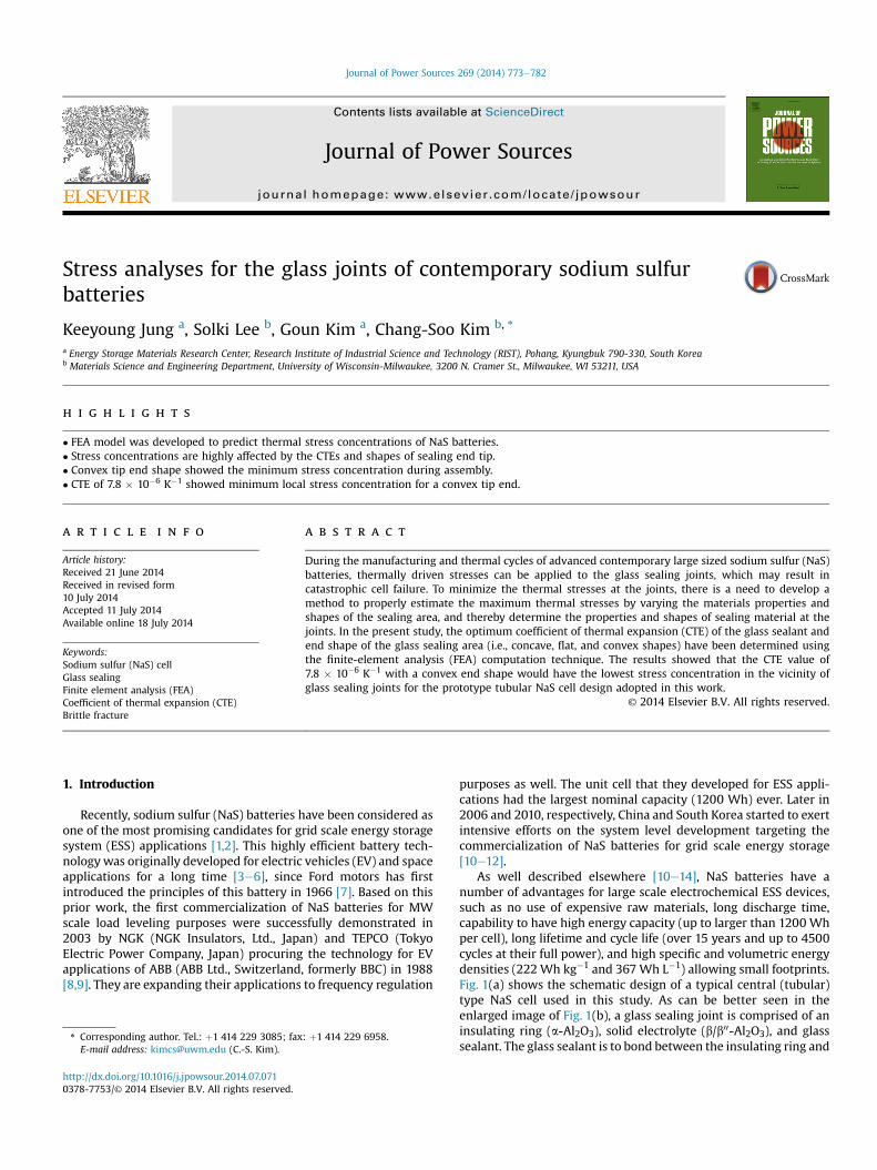
As well described elsewhere [10e14], NaS batteries have anumber of advantages for large scale electrochemical ESS devices,such as no use of expensive raw materials, long discharge time,capability to have high energy capacity (up to larger than 1200 Whper cell), long lifetime and cycle life (over 15 years and up to 4500cycles at their full power), and high specific and volumetric energydensities (222Wh kg�1 and 367 Wh L�1) allowing small footprints.Fig. 1(a) shows the schematic design of a typical central (tubular)type NaS cell used in this study. As can be better seen in theenlarged image of Fig. 1(b), a glass sealing joint is comprised of aninsulating ring (a-Al2O3), solid electrolyte (b/b00-Al2O3), and glasssealant. The glass sealant is to bond between the insulating ring and
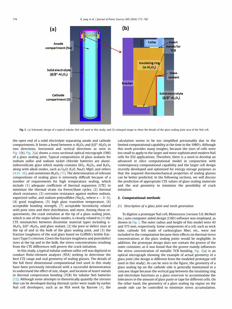
Fig. 1. (a) Schematic design of a typical tubular NaS cell used in this study, and (b) enlarged image to show the details of the glass sealing joint area of the NaS cell.
K. Jung et al. / Journal of Power Sources 269 (2014) 773e782774
the open end of a solid electrolyte separating anode and cathodecompartments. It forms a bond between a-Al2O3 and b/b00-Al2O3 intwo directions, horizontal and vertical directions as seen inFig. 1(b). Fig. 2(a) shows a cross-sectional optical micrograph (OM)of a glass sealing joint. Typical compositions of glass sealants forsodium sulfur and sodium nickel chloride batteries are alumi-noborosilicate glass which mainly contains SiO2, Al2O3, and B2O3,along with alkali oxides, such as Li2O, K2O, Na2O, MgO, and others[4,15e16], and sometimes Bi2O3 [17]. The determination of relevantcompositions of sealing glass is extremely difficult because of anumber of requirements for high temperature sealing, whichinclude (1) adequate coefficient of thermal expansion (CTE) tominimize the thermal strain via freeze/thaw cycles, (2) thermalshock resistance, (3) corrosion resistance against molten sodium,vaporized sulfur, and sodium polysulfides (Na2Sx, where x ¼ 3e5),(4) good toughness, (5) high glass transition temperature, (6)acceptable bonding strength, (7) acceptable hermiticity relatedwith pore sizes and their distribution, and more. Among these re-quirements, the crack initiation at the tip of a glass sealing joint,which is one of the major failure modes, is closely related to (1) theCTE mismatches between dissimilar material types including a-Al2O3, b/b00-Al2O3, and glass sealant, (2) the pore or defect sizes atthe tip of and in the bulk of the glass sealing joint, and (3) thefracture toughness of the seal glass based on Griffith's brittle frac-ture (Type I) criterion. Given the fracture toughness and pore/defectsizes at the tip and in the bulk, the stress concentrations resultingfrom the CTE differences will govern the crack initiation.
In this study, a typical tubular sodium sulfur cell was digitized toconduct finite-element analyses (FEA) seeking to determine thebest CTE range and seal geometry of sealing glasses. The details ofthe full three dimensional computational tool used in this studyhave been previously introduced with a successful demonstrationto understand the effect of size, shape, and location of insert metalsin thermal compression bonding (TCB) for tubular NaS batteries[12]. Although some attempts to theoretically quantify the stressesthat can be developed during thermal cycles were made by earlierNaS cell developers, such as an FEA work by Barrow [4], the
calculation seems to be too simplified presumably due to thelimited computational capability at the time in the 1980's. Althoughthis work provides many insights, because the sizes of cells weretoo small to apply to the larger andmore sophisticated modern NaScells for ESS applications. Therefore, there is a need to develop anadvanced in silico computational model in conjunction withcontemporary computational capability and the larger cell designrecently developed and optimized for energy storage purposes sothat the required thermomechanical properties of sealing glassescan be better predicted. In the following sections, we will discussthe prediction of appropriate CTE values of glass sealing materialsand the seal geometry to minimize the possibility of crackinitiation.
2. Computational methods
2.1. Description of a glass joint and mesh generation
To digitize a prototype NaS cell, Rhinoceros (version 5.0, McNeelInc.) auto computer-aided design (CAD) software was employed, asshown in Fig. 1. The outer radius and height of this model were 43and 375 mm, respectively. Some components of a cell, such as wicktube, cathode felt made of carbon/glass fiber, etc., were notincluded in the computation because their effects on thermal stressconcentrations at the glass sealing joints would be negligible. Inaddition, the prototype design does not contain the groove of theouter container, as it was found that the groove mainly influencesthe stress concentration of metallic TCB bonding. Fig. 2(a) is anoptical micrograph showing the example of actual geometry of aglass joint (the design is different from the modeled prototype cellused in this study). As can be seen in the figure, the geometry of aglass sealing tip on the cathode side is generally maintained in aconcave shape because the vertical gap between the insulating ringand electrolyte functions as a glass reservoir to accommodate thetolerances in the amount of glass paste or tape for different cells. Onthe other hand, the geometry of a glass sealing tip region on theanode side can be controlled to minimize stress accumulation.
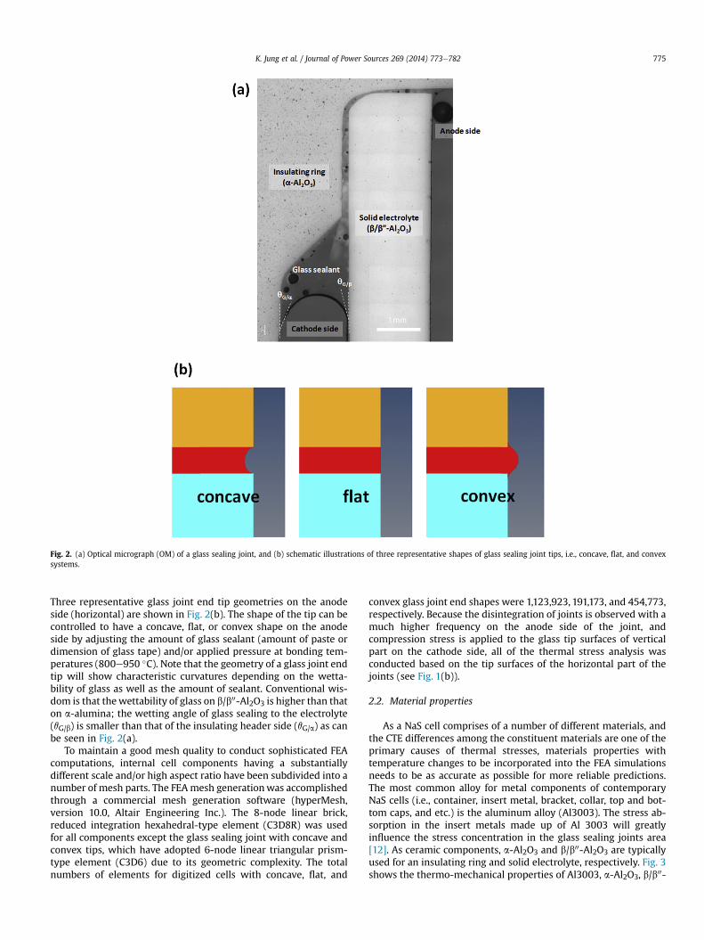
Fig. 2. (a) Optical micrograph (OM) of a glass sealing joint, and (b) schematic illustrations of three representative shapes of glass sealing joint tips, i.e., concave, flat, and convexsystems.
K. Jung et al. / Journal of Power Sources 269 (2014) 773e782 775
Three representative glass joint end tip geometries on the anodeside (horizontal) are shown in Fig. 2(b). The shape of the tip can becontrolled to have a concave, flat, or convex shape on the anodeside by adjusting the amount of glass sealant (amount of paste ordimension of glass tape) and/or applied pressure at bonding tem-peratures (800e950 �C). Note that the geometry of a glass joint endtip will show characteristic curvatures depending on the wetta-bility of glass as well as the amount of sealant. Conventional wis-dom is that thewettability of glass on b/b00-Al2O3 is higher than thaton a-alumina; the wetting angle of glass sealing to the electrolyte(qG/b) is smaller than that of the insulating header side (qG/a) as canbe seen in Fig. 2(a).
To maintain a good mesh quality to conduct sophisticated FEAcomputations, internal cell components having a substantiallydifferent scale and/or high aspect ratio have been subdivided into anumber of mesh parts. The FEAmesh generationwas accomplishedthrough a commercial mesh generation software (hyperMesh,version 10.0, Altair Engineering Inc.). The 8-node linear brick,reduced integration hexahedral-type element (C3D8R) was usedfor all components except the glass sealing joint with concave andconvex tips, which have adopted 6-node linear triangular prism-type element (C3D6) due to its geometric complexity. The totalnumbers of elements for digitized cells with concave, flat, and
convex glass joint end shapes were 1,123,923, 191,173, and 454,773,respectively. Because the disintegration of joints is observed with amuch higher frequency on the anode side of the joint, andcompression stress is applied to the glass tip surfaces of verticalpart on the cathode side, all of the thermal stress analysis wasconducted based on the tip surfaces of the horizontal part of thejoints (see Fig. 1(b)).
2.2. Material properties
As a NaS cell comprises of a number of different materials, andthe CTE differences among the constituent materials are one of theprimary causes of thermal stresses, materials properties withtemperature changes to be incorporated into the FEA simulationsneeds to be as accurate as possible for more reliable predictions.The most common alloy for metal components of contemporaryNaS cells (i.e., container, insert metal, bracket, collar, top and bot-tom caps, and etc.) is the aluminum alloy (Al3003). The stress ab-sorption in the insert metals made up of Al 3003 will greatlyinfluence the stress concentration in the glass sealing joints area[12]. As ceramic components, a-Al2O3 and b/b00-Al2O3 are typicallyused for an insulating ring and solid electrolyte, respectively. Fig. 3shows the thermo-mechanical properties of Al3003, a-Al2O3, b/b00-
K. Jung et al. / Journal of Power Sources 269 (2014) 773e782776
Al2O3, and glass that were used in the computation. Poisson's ratiosfor Al3003, a-Al2O3, b/b00-Al2O3, and glass were 0.33, 0.23, 0.23, and0.22, respectively [12]. The material properties were adopted fromexisting literature [12,18] or measured in-house. The CTEs of glass
Fig. 3. Material properties used in the computation to show (a) CTE (Al3003, alpha-and beta-alumina), (b) elastic modulus (Al3003, alpha- and beta-alumina, and glass),and (c) true plastic stressestrain curves for Al3003.
materials were measured by an extensometer in a vacuum furnace(Netzsch DIL 402C). The measured CTEs were close to a constant inthe temperature range of 25e520 �C and showed a sudden increaseabove the glass transition temperature, Tg. The modulus of the glasssealant was assumed to be very lowabove Tg.With this assumption,different values of CTEs in the range of 5.0e8.5 � 10�6 K�1 weretested to study the CTE effects of the glass sealants on the thermalstress concentrations during the assembly and the thaw-and-freezeprocesses.
2.3. Computation conditions
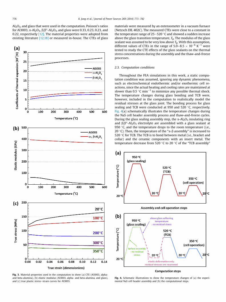
Throughout the FEA simulations in this work, a static compu-tation condition was assumed, ignoring any dynamic phenomena,such as electrochemical endothermic and/or exothermic cell re-actions, since the actual heating and cooling rates are maintained atslower than 0.5 �C min�1 to minimize any possible thermal shock.The temperature changes during glass bonding and TCB were,however, included in the computation to realistically model theresidual stresses at the glass joint. The bonding process for glasssealing and TCB were conducted at 950 and 520 �C, respectively.Fig. 4(a) schematically illustrates the temperature changes duringthe NaS cell header assembly process and thaw-and-freeze cycles.During the glass sealing assembly step, the a-Al2O3 insulating ringand b/b00-Al2O3 electrolyte are assembled with a glass sealant at950 �C, and the temperature drops to the room temperature (i.e.,20 �C). Then, the temperature of the “a-b assembly” is increased to520 �C for TCB. The TCB is to bond between metal (i.e., bracket andcollar) and the ceramic components with an insert metal. Thetemperature decrease from 520 �C to 20 �C of the “TCB assembly”
Fig. 4. Schematic illustrations to show the temperature changes of (a) the experi-mental NaS cell header assembly and (b) the computational steps.
K. Jung et al. / Journal of Power Sources 269 (2014) 773e782 777
will yield additional residual thermal stresses. With those residualstresses in the glass and TCB areas, all of the other remainingcomponents (i.e., container and cap) are finally assembled togethervia the electron beam welding (EBW) technology at 20 �C. Thethaw-and-freeze thermal cycle has been simulated by changing thesystem temperatures from 20/ 350/ 20 �C considering that thecell operation temperature is 350 �C. Assuming that glass softeningoccurs near 520 �C, the total simulation was subdivided intosimpler 2 steps to reflect this experimental procedure, i.e., (i) theglass sealing and TCB assembly step and (ii) the thaw-and-freezingthermal cycle step, as shown in Fig. 4(b) using the solid lines. Notethat the glass sealing assembly process has been simplified due tothe complete elastic characteristics of glass sealing, a-Al2O3, and b/b00-Al2O3 in the ranges of 520e20 �C and 20e520 �C, and the stepsin dotted/dashed lines of Fig. 4(b) were ignored.
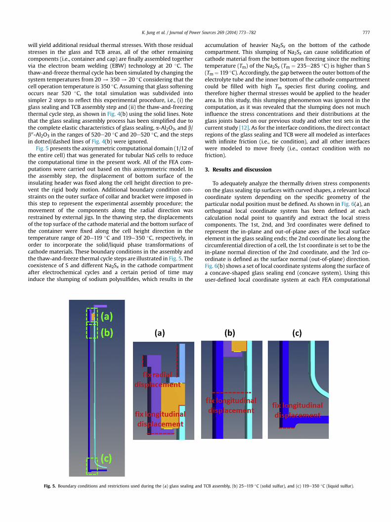
Fig. 5 presents the axisymmetric computational domain (1/12 ofthe entire cell) that was generated for tubular NaS cells to reducethe computational time in the present work. All of the FEA com-putations were carried out based on this axisymmetric model. Inthe assembly step, the displacement of bottom surface of theinsulating header was fixed along the cell height direction to pre-vent the rigid body motion. Additional boundary condition con-straints on the outer surface of collar and bracket were imposed inthis step to represent the experimental assembly procedure; themovement of the components along the radial direction wasrestrained by external jigs. In the thawing step, the displacementsof the top surface of the cathode material and the bottom surface ofthe container were fixed along the cell height direction in thetemperature range of 20e119 �C and 119e350 �C, respectively, inorder to incorporate the solid/liquid phase transformations ofcathode materials. These boundary conditions in the assembly andthe thaw-and-freeze thermal cycle steps are illustrated in Fig. 5. Thecoexistence of S and different Na2Sx in the cathode compartmentafter electrochemical cycles and a certain period of time mayinduce the slumping of sodium polysulfides, which results in the
Fig. 5. Boundary conditions and restrictions used during the (a) glass sealing and
accumulation of heavier Na2Sx on the bottom of the cathodecompartment. This slumping of Na2Sx can cause solidification ofcathode material from the bottom upon freezing since the meltingtemperature (Tm) of the Na2Sx (Tm ¼ 235e285 �C) is higher than S(Tm¼ 119 �C). Accordingly, the gap between the outer bottom of theelectrolyte tube and the inner bottom of the cathode compartmentcould be filled with high Tm species first during cooling, andtherefore higher thermal stresses would be applied to the headerarea. In this study, this slumping phenomenon was ignored in thecomputation, as it was revealed that the slumping does not muchinfluence the stress concentrations and their distributions at theglass joints based on our previous study and other test sets in thecurrent study [12]. As for the interface conditions, the direct contactregions of the glass sealing and TCB were all modeled as interfaceswith infinite friction (i.e., tie condition), and all other interfaceswere modeled to move freely (i.e., contact condition with nofriction).
3. Results and discussion
To adequately analyze the thermally driven stress componentson the glass sealing tip surfaces with curved shapes, a relevant localcoordinate system depending on the specific geometry of theparticular nodal position must be defined. As shown in Fig. 6(a), anorthogonal local coordinate system has been defined at eachcalculation nodal point to quantify and extract the local stresscomponents. The 1st, 2nd, and 3rd coordinates were defined torepresent the in-plane and out-of-plane axes of the local surfaceelement in the glass sealing ends; the 2nd coordinate lies along thecircumferential direction of a cell, the 1st coordinate is set to be thein-plane normal direction of the 2nd coordinate, and the 3rd co-ordinate is defined as the surface normal (out-of-plane) direction.Fig. 6(b) shows a set of local coordinate systems along the surface ofa concave-shaped glass sealing end (concave system). Using thisuser-defined local coordinate system at each FEA computational
TCB assembly, (b) 25e119 �C (solid sulfur), and (c) 119e350 �C (liquid sulfur).
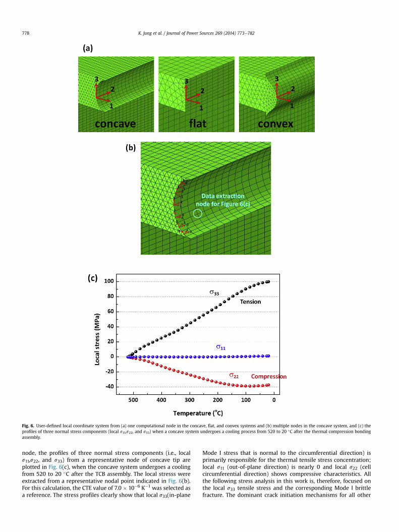
Fig. 6. User-defined local coordinate system from (a) one computational node in the concave, flat, and convex systems and (b) multiple nodes in the concave system, and (c) theprofiles of three normal stress components (local s11,s22, and s33) when a concave system undergoes a cooling process from 520 to 20 �C after the thermal compression bondingassembly.
K. Jung et al. / Journal of Power Sources 269 (2014) 773e782778
node, the profiles of three normal stress components (i.e., locals11,s22, and s33) from a representative node of concave tip areplotted in Fig. 6(c), when the concave system undergoes a coolingfrom 520 to 20 �C after the TCB assembly. The local stresss wereextracted from a representative nodal point indicated in Fig. 6(b).For this calculation, the CTE value of 7.0 � 10�6 K�1 was selected asa reference. The stress profiles clearly show that local s33(in-plane
Mode I stress that is normal to the circumferential direction) isprimarily responsible for the thermal tensile stress concentration;local s11 (out-of-plane direction) is nearly 0 and local s22 (cellcircumferential direction) shows compressive characteristics. Allthe following stress analysis in this work is, therefore, focused onthe local s33 tensile stress and the corresponding Mode I brittlefracture. The dominant crack initiation mechanisms for all other
K. Jung et al. / Journal of Power Sources 269 (2014) 773e782 779
test cases with different CTEs and glass sealing end shapes were thetensile Mode I fracture along the local 33 direction.
3.1. Stress distributions in the concave shaped glass sealing tip
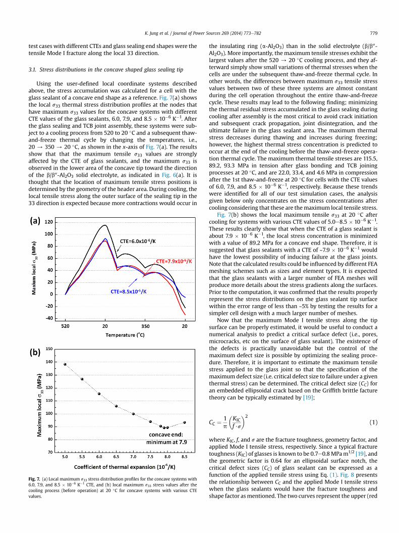
Using the user-defined local coordinate systems describedabove, the stress accumulation was calculated for a cell with theglass sealant of a concave end shape as a reference. Fig. 7(a) showsthe local s33 thermal stress distribution profiles at the nodes thathave maximum s33 values for the concave systems with differentCTE values of the glass sealants, 6.0, 7.9, and 8.5 � 10�6 K�1. Afterthe glass sealing and TCB joint assembly, these systems were sub-ject to a cooling process from 520 to 20 �C and a subsequent thaw-and-freeze thermal cycle by changing the temperatures, i.e.,20 / 350 / 20 �C, as shown in the x-axis of Fig. 7(a). The resultsshow that that the maximum tensile s33 values are stronglyaffected by the CTE of glass sealants, and the maximum s33 isobserved in the lower area of the concave tip toward the directionof the b/b00-Al2O3 solid electrolyte, as indicated in Fig. 6(a). It isthought that the location of maximum tensile stress positions isdetermined by the geometry of the header area. During cooling, thelocal tensile stress along the outer surface of the sealing tip in the33 direction is expected because more contractions would occur in
Fig. 7. (a) Local maximum s33 stress distribution profiles for the concave systems with6.0, 7.9, and 8.5 � 10�6 K�1 CTE, and (b) local maximum s33 stress values after thecooling process (before operation) at 20 �C for concave systems with various CTEvalues.
the insulating ring (a-Al2O3) than in the solid electrolyte (b/b00-Al2O3). More importantly, the maximum tensile stresses exhibit thelargest values after the 520 / 20 �C cooling process, and they af-terward simply show small variations of thermal stresses when thecells are under the subsequent thaw-and-freeze thermal cycle. Inother words, the differences between maximum s33 tensile stressvalues between two of these three systems are almost constantduring the cell operation throughout the entire thaw-and-freezecycle. These results may lead to the following finding; minimizingthe thermal residual stress accumulated in the glass sealing duringcooling after assembly is the most critical to avoid crack initiationand subsequent crack propagation, joint disintegration, and theultimate failure in the glass sealant area. The maximum thermalstress decreases during thawing and increases during freezing;however, the highest thermal stress concentration is predicted tooccur at the end of the cooling before the thaw-and-freeze opera-tion thermal cycle. The maximum thermal tensile streses are 115.5,89.2, 93.3 MPa in tension after glass bonding and TCB joiningprocesses at 20 �C, and are 22.0, 33.4, and 4.6 MPa in compressionafter the 1st thaw-and-freeze at 20 �C for cells with the CTE valuesof 6.0, 7.9, and 8.5 � 10�6 K�1, respectively. Because these trendswere identified for all of our test simulation cases, the analysisgiven below only concentrates on the stress concentrations aftercooling considering that these are themaximum local tensile stress.
Fig. 7(b) shows the local maximum tensile s33 at 20 �C aftercooling for systems with various CTE values of 5.0e8.5 � 10�6 K�1.These results clearly show that when the CTE of a glass sealant isabout 7.9 � 10�6 K�1, the local stress concentration is minimizedwith a value of 89.2 MPa for a concave end shape. Therefore, it issuggested that glass sealants with a CTE of ~7.9 � 10�6 K�1 wouldhave the lowest possibility of inducing failure at the glass joints.Note that the calculated results could be influenced by different FEAmeshing schemes such as sizes and element types. It is expectedthat the glass sealants with a larger number of FEA meshes willproduce more details about the stress gradients along the surfaces.Prior to the computation, it was confirmed that the results properlyrepresent the stress distributions on the glass sealant tip surfacewithin the error range of less than ~5% by testing the results for asimpler cell design with a much larger number of meshes.
Now that the maximum Mode I tensile stress along the tipsurface can be properly estimated, it would be useful to conduct anumerical analysis to predict a critical surface defect (i.e., pores,microcracks, etc on the surface of glass sealant). The existence ofthe defects is practically unavoidable but the control of themaximum defect size is possible by optimizing the sealing proce-dure. Therefore, it is important to estimate the maximum tensilestress applied to the glass joint so that the specification of themaximumdefect size (i.e. critical defect size to failure under a giventhermal stress) can be determined. The critical defect size (CC) foran embedded ellipsoidal crack based on the Griffith brittle facturetheory can be typically estimated by [19];
CC ¼ 1p
�KIC
f $s
�2(1)
where KIC, f, and s are the fracture toughness, geometry factor, andapplied Mode I tensile stress, respectively. Since a typical fracturetoughness (KIC) of glasses is known to be 0.7e0.8MPam1/2 [19], andthe geometric factor is 0.64 for an ellipsoidal surface notch, thecritical defect sizes (CC) of glass sealant can be expressed as afunction of the applied tensile stress using Eq. (1). Fig. 8 presentsthe relationship between CC and the applied Mode I tensile stresswhen the glass sealants would have the fracture toughness andshape factor asmentioned. The two curves represent the upper (red
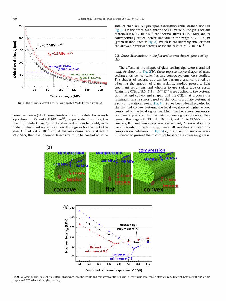
Fig. 8. Plot of critical defect size (CC) with applied Mode I tensile stress (s).
K. Jung et al. / Journal of Power Sources 269 (2014) 773e782780
curve) and lower (black curve) limits of the critical defect sizes withKIC values of 0.7 and 0.8 MPa m1/2, respectively. From this, themaximum defect size, CC, of the glass sealant can be readily esti-mated under a certain tensile stress. For a given NaS cell with theglass CTE of 7.9 � 10�6 K�1, if the maximum tensile stress is89.2 MPa, then the inherent defect size must be controlled to be
Fig. 9. (a) Areas of glass sealant tip surfaces that experience the tensile and compressive stshapes and CTE values of the glass sealing.
smaller than 48e63 mm upon fabrication (blue dashed lines inFig. 8). On the other hand, when the CTE value of the glass sealantmaterials is 6.0 � 10�6 K�1, the thermal stress is 115.5 MPa and itscorresponding critical defect size falls in the range of 29e37 mm(green dashed lines in Fig. 8), which is considerably smaller thanthe allowable critical defect size for the case of 7.9 � 10�6 K�1.
3.2. Stress distributions in the flat and convex shaped glass sealingtips
The effects of the shapes of glass sealing tips were examinednext. As shown in Fig. 2(b), three representative shapes of glasssealing ends, i.e., concave, flat, and convex systems were studied.The shapes of sealant tips can be designed and controlled byadjusting the amount of glass sealants, applied pressure, heattreatment conditions, and whether to use a glass tape or paste.Again, the CTEs of 5.0e8.5 � 10�6 K�1 were applied to the systemswith flat and convex end shapes, and the CTEs that produce themaximum tensile stress based on the local coordinate systems ateach computational point (Fig. 6(a)) have been identified. Also forthe flat and convex systems, the local s33 showed higher valuescompared to the local s11 or s22. Much smaller stress concentra-tions were predicted for the out-of-plane s11 components; theywere in the ranges of�10 to 4,�16 to�2, and�10 to 13MPa for theconcave, flat, and convex systems, respectively. Stresses along thecircumferential direction (s22) were all negative showing thecompression behaviors. In Fig. 9(a), the glass tip surfaces wereillustrated to present the maximum local tensile stress (s33) areas.
resses, and (b) maximum local tensile stresses from different systems with various tip
K. Jung et al. / Journal of Power Sources 269 (2014) 773e782 781
Shaded ellipsoids represent the maximum local tensile s11 areas,and arrows indicate the directions of the maximum tension ormaximum compression stresses, respectively. Note that stressdistributions along the local 3-direction is important as the cell hasa tubular geometry, and the positions for the shaded ellipsoids andarrows along the circumferential direction have been arbitrarilychosen for the purpose of visualization. From Fig. 9(a), it is clearthat for all three systems, stresses of the tension and compressionare predicted in the lower and upper parts of end tips, respectively.Similar to Fig. 7(b), the maximum local tensile stresses from thesystems with different tip shapes are then plotted as functions oftheir different CTEs in Fig. 9(b). The results show that, (i) the vari-ations of maximum s33 tensile stress can be substantially influ-enced by the shape of glass tip surface, and (ii) the best CTE valuesfor the three cases are different. In particular, it was predicted that alower glass CTE (6.8� 10�6 K�1) would lead to the best in resistanceto the brittle fracture compared to relatively higher CTEs in theconcave and convex systems. From the figure, it is seen that theconvex systemwith the glass CTE of 7.8� 10�6 K�1 would show thelowest maximum local s33, which should be preferable to havemore robust glass sealing joints. Although it can be intuitivelyinferred that the adequate CTE value of glass sealant would be5e8� 10�6 K�1 as the CTEs of a- and b”-alumina are in the windowof 5.3e8.8 � 10�6 K�1 in the temperature range of 20e520 �C (seeFig. 3(a)), the results can suggest better manufacturing guidance tominimize the probability of failure at the glass joints.
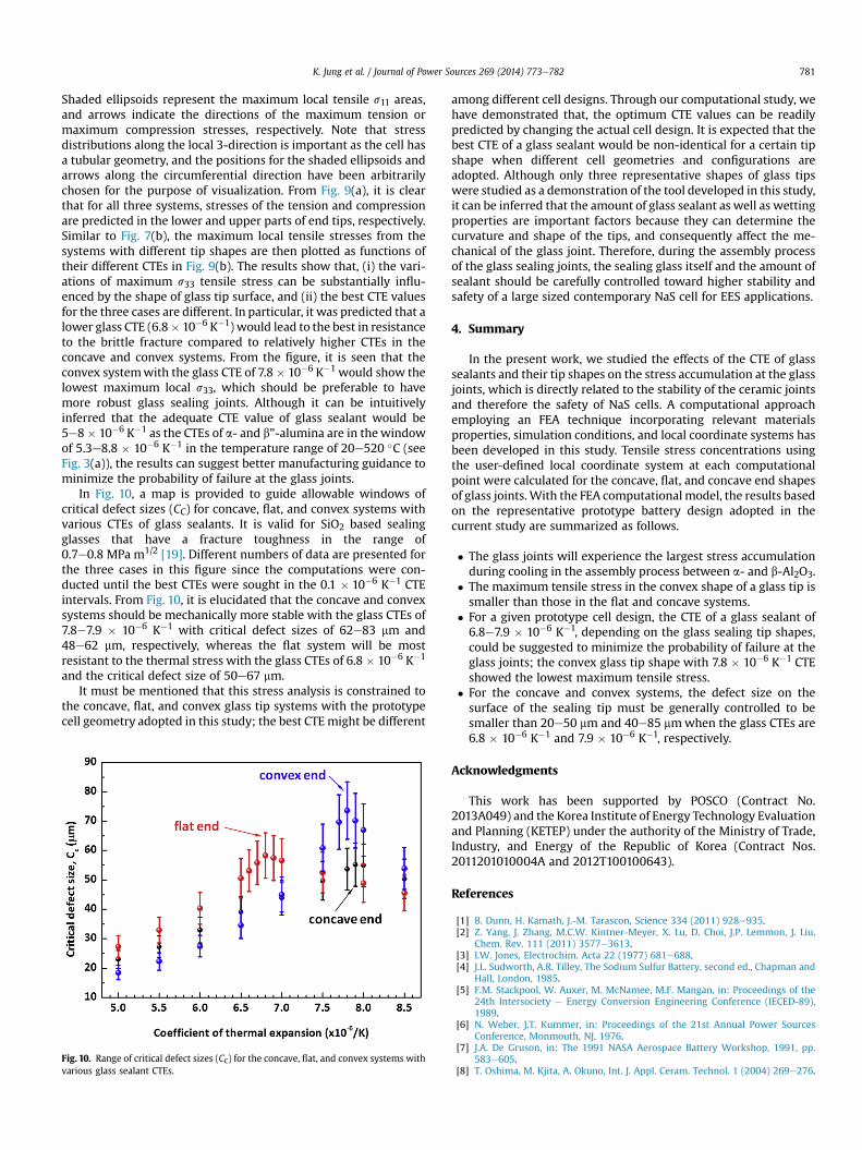
In Fig. 10, a map is provided to guide allowable windows ofcritical defect sizes (CC) for concave, flat, and convex systems withvarious CTEs of glass sealants. It is valid for SiO2 based sealingglasses that have a fracture toughness in the range of0.7e0.8 MPa m1/2 [19]. Different numbers of data are presented forthe three cases in this figure since the computations were con-ducted until the best CTEs were sought in the 0.1 � 10�6 K�1 CTEintervals. From Fig. 10, it is elucidated that the concave and convexsystems should be mechanically more stable with the glass CTEs of7.8e7.9 � 10�6 K�1 with critical defect sizes of 62e83 mm and48e62 mm, respectively, whereas the flat system will be mostresistant to the thermal stress with the glass CTEs of 6.8 � 10�6 K�1
and the critical defect size of 50e67 mm.It must be mentioned that this stress analysis is constrained to
the concave, flat, and convex glass tip systems with the prototypecell geometry adopted in this study; the best CTEmight be different
Fig. 10. Range of critical defect sizes (CC) for the concave, flat, and convex systems withvarious glass sealant CTEs.
among different cell designs. Through our computational study, wehave demonstrated that, the optimum CTE values can be readilypredicted by changing the actual cell design. It is expected that thebest CTE of a glass sealant would be non-identical for a certain tipshape when different cell geometries and configurations areadopted. Although only three representative shapes of glass tipswere studied as a demonstration of the tool developed in this study,it can be inferred that the amount of glass sealant as well as wettingproperties are important factors because they can determine thecurvature and shape of the tips, and consequently affect the me-chanical of the glass joint. Therefore, during the assembly processof the glass sealing joints, the sealing glass itself and the amount ofsealant should be carefully controlled toward higher stability andsafety of a large sized contemporary NaS cell for EES applications.
4. Summary
In the present work, we studied the effects of the CTE of glasssealants and their tip shapes on the stress accumulation at the glassjoints, which is directly related to the stability of the ceramic jointsand therefore the safety of NaS cells. A computational approachemploying an FEA technique incorporating relevant materialsproperties, simulation conditions, and local coordinate systems hasbeen developed in this study. Tensile stress concentrations usingthe user-defined local coordinate system at each computationalpoint were calculated for the concave, flat, and concave end shapesof glass joints.With the FEA computational model, the results basedon the representative prototype battery design adopted in thecurrent study are summarized as follows.
� The glass joints will experience the largest stress accumulationduring cooling in the assembly process between a- and b-Al2O3.
� The maximum tensile stress in the convex shape of a glass tip issmaller than those in the flat and concave systems.
� For a given prototype cell design, the CTE of a glass sealant of6.8e7.9 � 10�6 K�1, depending on the glass sealing tip shapes,could be suggested to minimize the probability of failure at theglass joints; the convex glass tip shape with 7.8 � 10�6 K�1 CTEshowed the lowest maximum tensile stress.
� For the concave and convex systems, the defect size on thesurface of the sealing tip must be generally controlled to besmaller than 20e50 mm and 40e85 mmwhen the glass CTEs are6.8 � 10�6 K�1 and 7.9 � 10�6 K�1, respectively.
Acknowledgments
This work has been supported by POSCO (Contract No.2013A049) and the Korea Institute of Energy Technology Evaluationand Planning (KETEP) under the authority of the Ministry of Trade,Industry, and Energy of the Republic of Korea (Contract Nos.2011201010004A and 2012T100100643).
References
[1] B. Dunn, H. Kamath, J.-M. Tarascon, Science 334 (2011) 928e935.[2] Z. Yang, J. Zhang, M.C.W. Kintner-Meyer, X. Lu, D. Choi, J.P. Lemmon, J. Liu,
Chem. Rev. 111 (2011) 3577e3613.[3] I.W. Jones, Electrochim. Acta 22 (1977) 681e688.[4] J.L. Sudworth, A.R. Tilley, The Sodium Sulfur Battery, second ed., Chapman and
Hall, London, 1985.[5] F.M. Stackpool, W. Auxer, M. McNamee, M.F. Mangan, in: Proceedings of the
24th Intersociety e Energy Conversion Engineering Conference (IECED-89),1989.
[6] N. Weber, J.T. Kummer, in: Proceedings of the 21st Annual Power SourcesConference, Monmouth, NJ, 1976.
[7] J.A. De Gruson, in: The 1991 NASA Aerospace Battery Workshop, 1991, pp.583e605.
[8] T. Oshima, M. Kjita, A. Okuno, Int. J. Appl. Ceram. Technol. 1 (2004) 269e276.
K. Jung et al. / Journal of Power Sources 269 (2014) 773e782782
[9] R. Bauer, W. Haar, H. Kleinschmager, G. Weddigen, W. Fischer, J. PowerSources 1 (1976/77) 109e126.
[10] Z. Wen, Y. Hu, X. Wu, J. Han, Z. Gu, Adv. Funct. Mater. 23 (2013) 1005e1018.[11] J.K. Min, C.-H. Lee, J. Power Sources 210 (2012) 101e109.[12] K. Jung, S. Lee, Y.-C. Park, C.-S. Kim, J. Power Sources 250 (2014) 1e14.[13] B.L. Ellis, L.F. Nazar, Curr. Opin. Solid State Mater. Sci. 16 (2012) 168e177.[14] X. Lu, G. Xia, J.P. Lemmon, Z. Yang, J. Power Sources 195 (2010) 2431e2442.
[15] T.I. Barry, G.S. Schajer, F.M. Stackpool, in: Deutscher Verlag fuer Schweis-stechnik Conference, West Germany, 1980.
[16] D.-S. Park, M.W. Breiter, B.S. Dunn, L. Navias, U.S. Patent, 1982, 4,341,849.[17] S. Song, Z. Wen, Q. Zhang, Y. Liu, J. Power Sources 195 (2010) 384e388.[18] Atlas of Stress-strain Curves, second ed., ASM International, 2002.[19] Y.-M. Chiang, D. Burnie III, W.D. Kingery, Physical Ceramics, John Wiley &
Sons, 1997.