Embed Size (px)
Citation preview

INTERNATIONAL JOURNAL OF CIVIL AND STRUCTURAL ENGINEERING
Volume 5, No 2, 2014
© Copyright by the authors - Licensee IPA- Under Creative Commons license 3.0
Research article ISSN 0976 – 4399
Received on September 2014 Published on November 2014 91
Strengthening and repairing of an existing steel bridge using post
tensioning Mohamed Ghannam1, Nabil S. Mahmoud1, Ahmed Badr1, Fikry A. Salem1
Structural Eng. Department, Faculty of Eng., Mansoura University
doi: 10.6088/ijcser.2014050009
ABSTRACT
This paper deals with strengthening and repairing of an existing steel box girder bridge by
using post tensioned cables. The bridge crosses the river Nile in Sherbeen city near Mansoura,
Dakahlia province, Egypt. The bridge has been closed years ago for cars and vehicles as well
as for navigation in the river Nile. It is required to reopen the bridge for light weight vehicles
and for its movable part to reopen for navigation again. The study for the bridge includes site
investigation and finite element (FE) analysis to calculate the failure load capacity for all the
bridge elements and the effect of post tensioning in increasing this capacity. The FE model
where verified against previous test results. ANSYS finite element program is used to build
the models of different parts of the bridge.
Keyword: Steel bridge, post tensioning, cables, box girder, ANSYS.
1. Introduction
Many researches have worked on strengthening different types of structures especially
bridges. There are many ways for strengthening bridges, from these ways: prestressing, using
fibre reinforcing polymer (FRP) and post tensioning. Ayyub et al. (1990) study prestressing
composite girders subjected to positive bending moment. Ayyub et al. (1992a) presented an
experimental study for prestressed composite girder subjected to negative bending moment;
Ayyub et al. (1992b) perform an analytical study for prestressed composite girder subjected
to negative moment. Nazir, (2003) present a research on prestressed arch steel bridge. Phares
et al. (2003) present a research on strengthening of steel girder bridges using FRP.
Post tensioning is one of the most effective methods for strengthening an existing structure to
overcome the increase in service load without replacement of parts of the structure, many
researches study this solution especially with bridge. Dunker et al. (1985a) present a research
on strengthening of existing single-span steel-beam and concrete deck bridges. Dunker et al.
(1985b) provide a design manual for strengthening single-span composite bridges by post-
tensioning. Klaiber et al. (1990) worked on, strengthening of an existing continuous-span,
steel-beam, concrete deck bridge by post-tensioning
This paper introduces a real application for using post tensioned cable in strengthening
bridges. The old Sherbeen Bridge is the case under study in the present paper. The bridge has
been closed years ago for cars and vehicles and also for navigation in this branch of the river
Nile. It is required to reopen the bridge for vehicles and for its movable part to reopen for
navigation again. The study for the bridge include site investigation and finite element
analysis to calculate the failure load capacity for the bridge elements and the effect of post
tensioning in increasing this capacity. ANSYS (2005) finite element program is used to build
the models for different parts of the bridge.
Strengthening and repairing of an existing steel bridge using post tensioning
Mohamed Ghannam et al.,
International Journal of Civil and Structural Engineering
Volume 5 Issue 2 2014
92
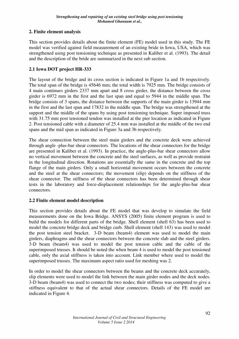
2. Finite element analysis
This section provides details about the finite element (FE) model used in this study. The FE
model was verified against field measurement of an existing bride in Iowa, USA, which was
strengthened using post tensioning technique as presented in Kaliber et al. (1993). The detail
and the description of the bride are summarized in the next sub section.
2.1 Iowa DOT project HR-333
The layout of the bridge and its cross section is indicated in Figure 1a and 1b respectively.
The total span of the bridge is 45646 mm; the total width is 7925 mm. The bridge consists of
4 main continues girders 2337 mm apart and 8 cross girder, the distance between the cross
girder is 6972 mm in the first and the last span and equal to 5944 in the middle span. The
bridge consists of 3 spans, the distance between the supports of the main girder is 13944 mm
in the first and the last span and 17832 in the middle span. The bridge was strengthened at the
support and the middle of the spans by using post tensioning technique. Super imposed truss
with 31.75 mm post tensioned tendon was installed at the pier location as indicated in Figure
2. Post tensioned cable with a diameter of 25.4 mm was installed at the middle of the two end
spans and the mid span as indicated in Figure 3a and 3b respectively.
The shear connection between the steel main girders and the concrete deck were achieved
through angle -plus-bar shear connectors. The locations of the shear connectors for the bridge
are presented in Kaliber et al. (1993). In practice, the angle-plus-bar shear connectors allow
no vertical movement between the concrete and the steel surfaces, as well as provide restraint
in the longitudinal direction. Rotations are essentially the same in the concrete and the top
flange of the main girders. Only a small horizontal movement occurs between the concrete
and the steel at the shear connectors; the movement (slip) depends on the stiffness of the
shear connector. The stiffness of the shear connectors has been determined through shear
tests in the laboratory and force-displacement relationships for the angle-plus-bar shear
connectors.
2.2 Finite element model description
This section provides details about the FE model that was develop to simulate the field
measurements done on the Iowa Bridge. ANSYS (2005) finite element program is used to
build the models for different parts of the bridge. Shell element (shell 63) has been used to
model the concrete bridge deck and bridge curb. Shell element (shell 143) was used to model
the post tension steel bracket. 3-D beam (beam4) element was used to model the main
girders, diaphragms and the shear connectors between the concrete slab and the steel girders.
3-D beam (beam4) was used to model the post tension cable and the cable of the
superimposed trusses. It should be noted the when beam 4 is used to model the post tensioned
cable, only the axial stiffness is taken into account. Link member where used to model the
superimposed trusses. The maximum aspect ratio used for meshing was 2.
In order to model the shear connectors between the beams and the concrete deck accurately,
slip elements were used to model the link between the main girder nodes and the deck nodes.
3-D beam (beam4) was used to connect the two nodes; their stiffness was computed to give a
stiffness equivalent to that of the actual shear connectors. Details of the FE model are
indicated in Figure 4.

Strengthening and repairing of an existing steel bridge using post tensioning
Mohamed Ghannam et al.,
International Journal of Civil and Structural Engineering
Volume 5 Issue 2 2014
93
(a) Bridge layout
(b) Bridge cross section
Figure 1: Layout and cross section of Iowa Bridge (Kaliber et al. 1993)
Figure 2: Details of the super imposed truss (Kaliber et al. 1993)
(a) End Span
(b) Middle Span
Figure 3: Details of post tensioned cable used at the end and middle span (Kaliber et al.
1993)

Strengthening and repairing of an existing steel bridge using post tensioning
Mohamed Ghannam et al.,
International Journal of Civil and Structural Engineering
Volume 5 Issue 2 2014
94
(a) Super imposed truss (b) post tensioning of the middle of the spans
Figure 4: FE model used to simulate Iowa Bridge
2.3 Verification of finite element model
The FE model was verified against the field measurement taken from the bridge. Three types
of loading conditions were used to verify the model. These loading conditions are discussed
below.
2.3.1 The post tension force in all super imposed trusses
The Applied post tension force in all the super imposed truss was 721.2 kN. Figure 5 shows
the comparison between field measurements and the FE model result for the value of strains
in the two outer main girders (North and South as indicated in Figure 1a). As can be seen
from Figure 5, there is a reasonable agreement between the field measurement and the FE
models results.
Figure 5: Strain result for after all super imposed truss is post tensioned.
2.3.2 Post tension force in the west north super imposed trusses (as indicated in Figure
1a)
The second loading condition is to post tension the west north super imposed truss with 721.2
kN. The measured deflection in the North girder was 0.22 mm and the obtained deflection
form the FE model was 0.3 mm which is close to the measured value.
2.3.3 The truck load (1.5) truck (as indicated in Figure 1a)

Strengthening and repairing of an existing steel bridge using post tensioning
Mohamed Ghannam et al.,
International Journal of Civil and Structural Engineering
Volume 5 Issue 2 2014
95
The third load condition is to apply post tension load to all cables plus a truck load (500400
kN) located in the lower middle part of the bridge as indicated in Figure 1a. The total strain
measured in the mid span of the North and south Main girder was 74 and 110 Micro strain
respectively. The calculated Total strain from the FE model for the North and South main
girder was 63 and 102 Micro strain respectively, which shows reasonable agreement with
field measurements.
3. Description of the bridge under study (Sherben Bridge)
This section provides some details about the bridge under study (Sherben Bridge). The bridge
details were provided by Mohsen et al. (2006). The bridge consists of 10 equal spans and
each has a length of 26 m. The two middle spans are movable spans as indicated in Figures
6a. The floor of the bridge has a width of 7.5 m with 1m side walk at each side so the width
of the road way is 5.5m. The floor is orthotropic plate of 10 mm thickness and has
longitudinal ribs of 150*10mm. The cross girders are repeated every 2180 mm with I-section
(240×10/400×8). Between each two cross girders there is two back to back C-channels. The
side walk is supported by a small arched truss every 2.18m at the location of the two back to
back C-channels. The side walk and the floor are illustrated in Figures 6b.
The main girder for the bridge is a box section with 2000 mm width and 2000 mm height.
The flange of the box section has a thickness of 18mm and the web thickness is 10 mm. The
upper and the lower flanges of the bridge are connected to the web by using two equal angles
80×8 as shown in Figure 7. The box girder has entire diaphragm 10 mm thick each 2180 mm
along the bridge. Each diaphragm consists of plate 400 mm width at top and bottom and 220
mm at the middle. At the mid distance between the diaphragms there are vertical stiffeners of
thickness 10 mm. The lower flange is stiffened using two longitudinal T-sections
(150×80×10 mm) as shown in Figure 7.
As it was difficult to test the material properties of the main part of the bridge, the steel
material of the bridge is assumed to be mild steel 37 as per the Egyptian code (ECP 205
2008). The steel material has a yielding stress of 240 MPa, young’s modulus of 2100 MPa.
(a) Sherben bridge (b) Side wake
Figure 6: general view for Sherben Bridge

Strengthening and repairing of an existing steel bridge using post tensioning
Mohamed Ghannam et al.,
International Journal of Civil and Structural Engineering
Volume 5 Issue 2 2014
96
Figure 7: Cross section for Sherben Bridge’s box girder
4. Strengthening the bridge
4.1 Strengthening the continuous part of the bridge
Figure 8 (a and b) shows the finite element (FE) model for the continuous part of the bridge.
In this model the supports are at the ends of the diaphragm at the location of the internal piers,
the length of the girder is taken to be 26 m. After applying a line load on the box girder, it
was found that the bridge failed at a load equal to 340 kN/m’ (distributed load on the upper
flange of the bridge= 170 kN/m2). The maximum bending stress at the flange was 289.6 MPa
as indicated in Figure 8a and the maximum shear stress at the web =141.3 MPa as indicated
in Figure 8b.
(a) Bending stress (b) Shear stress
Figure 8: Failure stresses at the continuous girder without strengthening.
In order to strengthen the continuous part of the bridge using post tensioning, cables has to be
positioned in the positive (lower flange) and the negative moment (upper flange) region. The
brackets that are holding the cables in the positive moment region are at 4360 mm from the
middle of the span. The cables have an eccentricity of 500 mm below the lower flange. The
brackets in the negative moment region are at 3270 mm from the piers. The cables have an
eccentricity of 100 mm below the upper flange.
Figure 9 shows the brackets that are holding the post tensioned cables in the positive and the
negative moment region. In the negative moment region, the brackets, stiffeners and vertical
diaphragm plates are used of 50 mm thickness and the plates where the cables are directly
attached are 100 mm thickness. The upper and the lower flange were strengthened by an
additional plate of 30 mm thickness and a width of 600 mm in order to sustain the
concentration of stresses due to the post tensioning load. In the positive moment region, the

Strengthening and repairing of an existing steel bridge using post tensioning
Mohamed Ghannam et al.,
International Journal of Civil and Structural Engineering
Volume 5 Issue 2 2014
97
brackets, stiffeners and vertical diaphragm plates are used of 80 mm thick. The plates where
cables are attached are 100 mm thick. The upper reinforced plate has a width of 1200 mm and
a thickness of 50 mm. The lower reinforced plate has a thickness of 30 mm and a width of
600 mm.
Figure 9: Post tensioning the continuous girder of the bridge.
4.2 Strengthening the movable part of the bridge
Figure 10 shows the FE model for this part of the bridge. In this model the supports are
considered at the ends of the diaphragm at the location of the movable pier, the length of the
cantilever is taken to be 22 m, this model failed at a load 95.4 kN/m’( distributed load on the
upper flange of the bridge= 47.7 kN/m2). The maximum bending stress at the flange =272.3
MPa as indicated in Figure 10a and the maximum shear stress on the web =78.48 MPa as
indicated in Figure 10b.
(a) Bending stress (b) Shear stress
Figure 10: Failure stresses at the movable girder without strengthening.
In order to strength this part with post tensioning cable, the cable has to be located in the
negative moment region (top flange). The bracket is installed at 3270 mm from the movable
pier. The bracket is formed of a vertical plate joining between the upper and the lower flange
of the bridge and also between the webs. This plate is supported by vertical stiffeners each
167 mm, the cable is attached to the vertical plate at 100 mm below the upper flange; the

Strengthening and repairing of an existing steel bridge using post tensioning
Mohamed Ghannam et al.,
International Journal of Civil and Structural Engineering
Volume 5 Issue 2 2014
98
thickness of the plate and the stiffeners is 40 mm. The cables are at 167 mm apart. The first
stiffener is at 499 mm from the web and the width of the stiffeners is 300 mm. There is
reinforced plate of 22 mm over the flange plate at the location of connection of the stiffeners
with the flange. The reinforced plate width is 40cm at the lower flange and 500 mm at the
upper flange. The details are indicated in Figure 11.
Figure 11: Post tensioning the movable girder of the bridge.
When the movable part of the bridge is closed, its structural system will be converted from
double cantilevers into one continuous beam as shown in Figure 12. Post tensioning the cable
in the negative moment region only will has no significant effect in strengthening the
movable part when it is closed, because the positive moment region of the girder will not be
reduced. It was decided to post tension the cable in the negative (top flange) and the positive
moment (bottom flange) region. When this method is used with the cantilever case it will also
lead to increase in the failure load. Although the cables that are attached under the lower
flange will increase the bending moment when the bridge is open, this increase is not
significant as the moment in this region has a very small value as indicated in figure 12a. The
bracket in the positive moment region will be the same as used in the continuous girder.
(a) Movable girder is opened (b) Movable girder is opened
Figure 12: Structural systems for the movable girder when opened and closed
5. Results and discussion
5.1 Results and analysis for the continuous part
From the Finite element (FE) model result, It was found that the failure load for the
continuous girder increase by 26.6%. The failure load increased from 170 kN/m2 to 215
kN/m2. This failure load equal 3.63 times the load obtained from ECP No.201 (2008) which
is equivalent to 59.2 kN/m2. Also the failure load equal 1.8 times the load obtained from the
AASHTO LRFD (2008) which equivalent to 120 kN/m2. Figures 13 a and b illustrate the
bending and the shear stresses at the failure load respectively.

Strengthening and repairing of an existing steel bridge using post tensioning
Mohamed Ghannam et al.,
International Journal of Civil and Structural Engineering
Volume 5 Issue 2 2014
99
(a) Bending stress (b) Shear stress
Figure 13: Failure stresses at the continuous girder after post tensioning.
5.2 Results and Analysis for the Cantilever Part
From the Finite element (FE) model result, it was found that when the bridge is open, the
failure load for the movable girder increase from 47.7 to 59 kN/m2 when post tensioning is
used, which is an increase of 24%. The failure stress for bending and shear is illustrated in
Figures 14 a and b respectively.
(a) Bending stress (b) Shear stress
Figure 14: Failure stresses at the movable girder after post tensioning.
5.3 Conclusions
In this paper, finite element (FE) model using ANSYS Software was provided to simulate the
strengthening of an existing bridge using post tensioning technique. The FE model was
verified against the field measurement of an existing bridge in USA that has been
strengthened using post tensioned cable. The FE model has reasonable agreement with the
field measurement. The verified FE model was then used in an analytical study to strengthen
an existing bridge crossing the river Nile in Egypt. It was found the strengthening the bridge
using post tensioned cable can increase the load-carrying capacity of the bridge by 25 %. The
vehicle loads indicated in the ECP No. 201 (2008) can be used in loading the bridge with a
factor of safety equal 3.63. This factor of safety will be 1.8 if the AASHTO LRFD (2008)
specification code is used for loading. So the bridge can be reopened again for the traffic and
its movable part to reopen for navigation.
6. References
1. ANSYS (2005), Verification Manual, Release 10.0. ANSYS, Inc., 275 Technology
Drive, Canonsburg, PA 15317, United States.
2. Ayyub, B.M., Sohn Y.G and Saadatmanesh,H, (1990), Prestressed composite girder
under positive moment, journal of structural Engineering 116(11), pp 2931–2951.

Strengthening and repairing of an existing steel bridge using post tensioning
Mohamed Ghannam et al.,
International Journal of Civil and Structural Engineering
Volume 5 Issue 2 2014
100
3. Ayyub, B.M., Sohn, Y.G. and saadatmanesh, H., (1992a), Prestressed composite
girder I: experimental study for negative, journal of structural engineering, 118(10),
pp 2743-2762.
4. Ayyub, B.M., Sohn, Y.G. and Saadatmanesh, H., (1992b), Prestressed composite
Girder II : Analytical study for negative moment, journal of structural engineering ,
118(10), pp 2763–2782.
5. Dunker, K. F., Klaiber, F. W., Beck, B. L. and Sanders, W.W., (1985a), Strengthening
of existing single-span steel-beam and concrete deck bridges, Final Report Part II.
ISU- HR-238, ERI Project 1536, ERIAmes-85231: Engineering Research Institute,
Iowa State University, Iowa Department of Transportation Highway Division and the
Iowa Highway Research Board.
6. Dunker, K. F., Klaiber, F. W. and Sanders, W.W., (1985b), Design manual for.
strengthening single-span composite bridges by post-tensioning, Final Report- Part III
HR-238, ERI Project 1536,ISU-ERI- Ames- 85229, Engineering Research Institute,
Iowa State University, Iowa Department of Transportation Highway Division and the
Iowa Highway Research Board.
7. Egyptian Code for Calculating Loads and Forces on Structures, code no. ECP 201
first edition (2008). Ministry of Housing, Utilities and Urban Communities, Housing
and Building National Research Centre, Cairo, Egypt.
8. Egyptian Code of Practice for Steel Construction and Bridges (Allowable stress
design) code no. ECP 205- 2001- Edition , (2008). Ministry of Housing, Utilities and
Urban Communities, Housing and Building Research National Centre, Cairo, Egypt.
9. Klaiber, F. W., Dunker, K. F., Planck, S. M. and Sanders W.W., (1990),
Strengthening of an existing continuous-span, steel-beam, concrete deck bridge by
Post-.Tensioning, Final Report, ISU-ERI-Ames -90210. Ames: Engineering Research
Institute, Iowa State University, Iowa Department of Transportation Highway
Division and the Iowa Highway Research Board.
10. Klaiber, F.W., Wipf, T.J., Fanous F. S., Bosch T. E. and El-Arabaty H. (1993),
Strengthening of an existing continuous-span, steel-stringer, concrete-deck bridge,
Final Report, HR-333, ISU-ERI-Ames- 94403Sept, Engineering Research Institute,
Iowa State University, Iowa Department of Transportation Highway Division and the
Iowa Highway Research Board.
11. Mohsen, H.A., Dessouki, A.K, Ibrahim, S.A. (2006). “Assessment and rehabilitation
of Sherbeen roadway bridge: case study “International conference on bridge
management systems Monitoring Assessment and rehabilitation, Housing and
Building National Research Centre, Cairo, Egypt, 21-23 March, 2006.
12. Nazir, C.P., (2003), Prestressed steel arch bridge, IE (I) Journal .CV, 84, pp 72-76.
13. Phares, B.M., Wipf, T.J., Klaiber, F. W., Abu-Hawash, A. and Lee Y., (2003),
Strengthening of steel girder bridges using FRP" Proceedings of the 2003 Mid-
Continent Transportation Research Symposium, Ames, Iowa, pp 1-12.