Embed Size (px)
Citation preview
Strength Prediction of Corbels Using Strut-and-Tie Model Analysis
Wael Kassem*
(Received June 2, 2014, Accepted May 6, 2015, Published online May 30, 2015)
Abstract: Astrut-and-tie basedmethod intended for determining the load-carrying capacity of reinforced concrete (RC) corbels is presented
in this paper. In addition to thenormal strut-and-tie force equilibrium requirements, the proposedmodel is basedon secant stiffness formulation,
incorporating strain compatibility and constitutive laws of crackedRC.Theproposedmethod evaluates the load-carrying capacity as limitedby
the failure modes associated with nodal crushing, yielding of the longitudinal principal reinforcement, as well as crushing or splitting of the
diagonal strut. Load-carrying capacity predictions obtained from the proposed analysismethod are in a better agreementwith corbel test results
of a comprehensive database, comprising 455 test results, compiled from the available literature, than other existing models for corbels. This
method is illustrated to provide more accurate estimates of behaviour and capacity than the shear-friction based approach implemented by the
ACI 318-11, the strut-and-tie provisions in different codes (American, Australian, Canadian, Eurocode and New Zealand).
Keywords: corbels, load-carrying capacity, shear strength, strut-and-tie model.
1. Introduction
Reinforced concrete (RC) corbels, defined as short cantileversjutting out from walls or columns having a shear span-to-depthratio, av/d, normally less than 1, are commonly used to supportprefabricated beams or floors at building joints, allowing, at thesame time, the force transmission to the vertical structuralmembers in precast concrete construction. Corbels are primarilydesigned to resist vertical loads and horizontal actions owing torestrained shrinkage, thermal deformation and creep of thesupported beam and/or breaking of a bridge crane. They arebecoming a common feature in building construction with theincreasing use of precast concrete. Owing to their geometricproportions, corbels are commonly classified as a discontinuityregion (D-region), where the strain distribution over their cross-section depth is nonlinear, even in the elastic stage (MacGregorand Wight 2009), and their strength is predominantly controlledby shear rather than flexure (Yang and Ashour 2012).The ACI 318-11 code (ACI Committee 318 2011) requires
corbels having shear span-to-depth ratio, av/d, less than 2 tobe designed using the strut-and-tie method and those withshear-to-span ratio less than 1 to be designed either usingstrut-and-tie method, or by the closely related traditionalACI design method based on shear-friction approach.However, the shear-friction hypothesis has little correlationwith the observed failure phenomenon of concrete crushingin the diagonal strut (Hwang et al. 2000b).
Strut-and-tie models (STM) have been generally recog-nized as an acceptable rational design approach for D-regionmembers including deep beams and corbels (Schlaich et al.1987). In addition, most current design codes [ACI Com-mittee 318; Australian code AS 3600 (2009); Canadian code(CSA A23.3-04); Eurocode 2 (2004) and New Zealand code(NZS 3101-1)] have recommended the STM approach as adesign tool for RC corbels. However, shear capacity ofcorbels evaluated from STMs and available formulae andcomputing procedures showed substantial scatter whencompared to experimental results (Hwang et al. 2000b; Aliand White 2001; Russo et al. 2006). A rational design pro-cedure to produce safe and economic corbels is thereforerequired.In the current paper, a strut-and-tie based method intended
for determining the load-carrying capacity of corbels is pre-sented. In addition to the normal strut-and-tie force equilib-rium requirements, the proposed model accounts for straincompatibility and constitutive laws of cracked reinforcedconcrete, and uses a secant stiffness formulation. A similarapproach was used previously to calculate the shear capacityof of squat walls (Hwang et al. 2001), deep beams (Hwangand Lee 2000), beam-column joints (Hwang and Lee 1999,2000, 2002), dapped-end beams (Lu et al. 2003), and corbels(Hwang et al. 2000a), while using a statically indeterminatetruss for modeling the flow of forces and an approximateestimation of members stiffness in evaluating the capacity.
2. Research Significance
In the present study, a strut-and-tie based method is de-veloped for calculating the load-carrying capacity of rein-forced concrete corbels. The proposed method is based on an
Division of Construction Engineering, College of
Engineering at Al-Qunfudah, Umm Al-Qura University,
P.O. BOX 288, Al-Qunfudah 21912, Saudi Arabia.
*Corresponding Author; E-mail: [email protected]
Copyright � The Author(s) 2015. This article is published
with open access at Springerlink.com
International Journal of Concrete Structures and MaterialsVol.9, No.2, pp.255–266, June 2015DOI 10.1007/s40069-015-0102-yISSN 1976-0485 / eISSN 2234-1315
255
iterative, secant stiffness formulation and employs constitu-tive laws for cracked reinforced concrete, while consideringstrain compatibility. The secant stiffness formulation ap-proach has previously been implemented in nonlinear finiteelement procedures to predict the nonlinear response of re-inforced concrete membrane elements (Vecchio 1989), aswell as to estimate the load-carrying capacity of deep beams(Park and Kuchma 2007). The method accounts for thefailure modes due to crushing of the nodal compression zoneat the top of the diagonal strut, yielding of the longitudinalreinforcement, as well as that of strut crushing or splitting.This method is used successfully to predict the load-carryingcapacity of 455 corbels that have been tested experimentally.The findings illustrate that the strut-and-tie model proposedby different code provisions provide conservative and scat-tered estimates of the strength of corbels, which should beexpected since these provisions were developed for the de-sign of all forms of discontinuity regions and not explicitlyfor corbels.
3. Compatibility-Based Strut-and-Tie ModelApproach for Corbels
Strut-and-tie modelling is a generalisation of the trussanalogy in which a structural continuum is transformed intoa discrete truss with compressive forces being resisted byconcrete and tensile forces by reinforcement. The method isbased on the lower bound theorem of plasticity. Conse-quently, there are an unlimited number of possible solutions
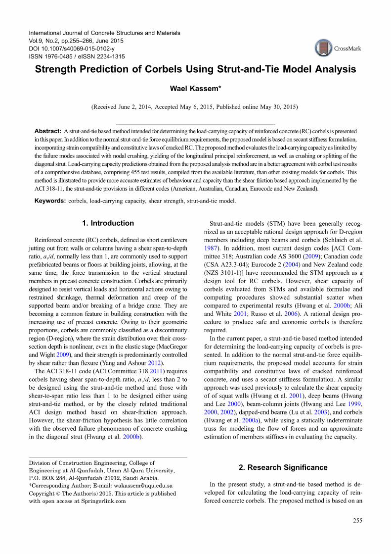
with only some having sufficient ductility for the assumedstress distribution to develop. In the proposed approach, asimple and statically determinate strut-and-tie load path isproposed to model the force transferring within the corbel asshown in Fig. 1. Statically determinant model requires noknowledge of the member stiffness which makes it simple tocalculate member forces using simple statics rules. Theproposed strut-and tie models assumes that the corbel resiststhe loads by compressive struts feeding directly into thecolumn, and a tension tie is required to resist the out-of-balance forces at the loading point.
4. Equilibrium Conditions
Figure 1 presents loads acting on a corbel and the pro-posed force transferring mechanisms in view of the proposedstrut-and-tie model. For corbels with short span-to-depthratios, a large portion of the applied vertical shear force isdirectly transferred to the supporting columns or wallsthrough inclined strut, with the formation of a full-lengthhorizontal tie to balance the thrust of the inclined struts(Fig. 1). The corbel is loaded by the vertical force Vcv ap-plied at the distance av from the column face and it is as-sumed that the horizontal outward load, Nu, is directlyapplied at the centroid of the principal tensile reinforcementand the effect of shifting is neglected for simplicity (Hwanget al. 2000b). The angle between the compressed diagonalconcrete strut and the horizontal direction /, can be definedas (Russo et al. 2006):
Fig. 1 Geometry and strut-and-tie model with forces acting on corbel.
256 | International Journal of Concrete Structures and Materials (Vol.9, No.2, June 2015)
/ ¼ tan�1 Z
av
� �ð1Þ
where Z is the distance of the lever arm from the centroid ofthe principal tension steel to the resultant compressive forceand av is the shear span. According to linear bending theory,the lever arm Z of a singly reinforced rectangular section canbe estimated as (Hwang et al. 2000a):
Z ¼ d � kd
3ð2Þ
where d is the effective depth of the corbel; kd is the depth ofthe neutral axis of the cross section; and coefficient k can bedefined as (Hwang et al. 2000b):
k ¼ffiffiffiffiffiffiffiffiffiffiffiffiffiffiffiffiffiffiffiffiffiffiffiffiffiffiffiffiffiffiffiðnqf Þ2 þ 2nqf
q� nqf ð3Þ
in which n is the ratio of the elastic moduli of steel andconcrete, n = Es/Ec, and the flexural reinforcement ratio qfis assumed to be given by:
qf ¼ As þ XAsh � An
bdð4Þ
where An is the cross-sectional area of principalreinforcement used to resist the applied outward load,taken as An = Nu/fys, where fys is the yielding strength ofthe principal reinforcement, As and Ash are the cross-sectional areas of the principal tensile reinforcement andhorizontal web reinforcement, respectively, and X is anefficiency factor representing the contribution of the webhorizontal reinforcement, assumed equal to 0.2 (He et al.2012). The value of n is obtained by assuming, from ACI318-11, that Es = 200 GPa and Ec ¼ 4700
ffiffiffiffif 0c
p(MPa), it
follows that:
n ¼ 42:6=ffiffiffiffif 0c
p: ð5Þ
The diagonal strut is assumed to have a bottle-shaped form.That is, it spreads laterally along its length. The lateral spreadingof the bottle-shaped strut introduces tensile force transverse tothe strut, Fst. The tensile force could potentially cause crackingalong the length of the strut resulting in a premature failure.Hence, transverse skin reinforcement should be provided inorder to control the cracking. The strut compressive force isassumed to spread at a 2:1 slope (longitudinal: transversedirection) as suggested by the ACI 318-11. The considered strut-and-tie model leads to the following equilibrium equations:
Dc ¼ Vcv
sin /ð6Þ
Hc ¼ Vcv
tan /ð7Þ
Fst ¼ Vcv
4 sin /ð8Þ
where Dc, Hc are the compressive forces in the diagonal andhorizontal concrete struts, respectively; and Fst is the
bursting tensile force in the tie of the strut-and-tie model.Because the bursting force Fst represents a quarter of thecompressive force of the diagonal strut, Dc, the horizontaland vertical components, Fsh and Fsv, of the tie force can beobtained from equilibrium as follows:
Fsh ¼ Vcv
4¼ Ds sin /
4ð9Þ
Fsv ¼ Vcv
4 tan /¼ Ds cos /
4: ð10Þ
4.1 Secant Stiffness FormulationThe proposed procedure is based on a compatibility—based
iterative, secant stiffness formulation and employs constitu-tive relations for cracked concrete and reinforcement. Thesecant stiffness approach was used to calculate the normalstrains in the horizontal concrete strut, diagonal concrete strut,horizontal web steel, vertical web steel, and the longitudinalsteel tie according to the following equations:
ed ¼ Dc
EdAdð11Þ
ec ¼ Hc
EcAcð12Þ
eh ¼ 2Fsh
EshAshð13Þ
ev ¼ 2Fsv
EsvAsvð14Þ
es ¼ TsEsAs
ð15Þ
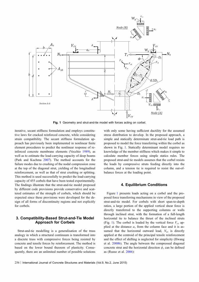
where Ad, Ac are the cross-sectional areas of the diagonal andhorizontal concrete struts; Ash, Asv and As are the cross-sectional areas of horizontal, vertical and longitudinal steelties; Ed ; Ec; Esh; Esv andEs, are the corresponding secantmoduli. Given compatible stress and strain fields, secantmoduli can be defined for the concrete and reinforcement(shown in Fig. 2). Secant moduli can be estimated by (Parkand Kuchma 2007):
Ed ¼ r2ded
ð16Þ
Ec ¼ r2cec
ð17Þ
Esh ¼ fsheh
ð18Þ
Esv ¼ fsvev
ð19Þ
Es ¼ fses
ð20Þ
where r2d; r2c; fsh; fsv and fs are the uniaxial stresses that areobtained from the constitutive relations of each member.
International Journal of Concrete Structures and Materials (Vol.9, No.2, June 2015) | 257
5. Constitutive Relationships of Concreteand Steel
5.1 Softened Concrete in CompressionCracked reinforced concrete in compression has been
observed to exhibit lower strength and stiffness comparedwith uniaxially compressed concrete, see Fig. 2a. Thisphenomenon of strength and stiffness reduction is com-monly referred to as compression softening. Applying thissoftening effect to the strut-and-tie model, it is recognizedthat the tensile straining perpendicular to the strut will re-duce the capacity of the concrete strut to resist compressivestresses. The stress in the concrete is determined from thestrains according to the following equations (Vecchio andCollins 1993):
• The ascending branch
r2 ¼ Wf 0c 2e2We0
� �� e2
We0
� �2" #
e2We0
� �� 1 ð21aÞ
• The descending branch
r2 ¼ W f 0c 1� ðe2=we0Þ � 1
4=w� 1
� �2" #
e2We0
� �� 1 ð21bÞ
W ¼ 1
1 þ kckfkc ¼ 0:35
�e1e2
� 0:28
� �0:8
� 1:0
kf ¼ 0:1825ffiffiffiffif 0c
p� 1:0
where r2 is the average principal stress of concrete in the 2direction; w is the softening coefficient; f 0c is the compressivestrength of a standard concrete cylinder in unit of MPa; e2and e1 are the average principal strains in the 2 and 1directions, respectively; and e0 is the concrete cylinder straincorresponding to the cylinder strength f 0c , which can bedefined approximately as:
e0 ¼ 0:002 þ 0:001f 0c � 20
80
� �20 � f 0c � 100MPa:
ð22Þ
6. Reinforcing Steel
The stress–strain relationship of steel is assumed to belinear up to yielding, followed by a yield plateau (Fig. 2b).This elastic–perfectly plastic type of stress–strain relation-ship is represented mathematically by:
fs ¼ Eses for es � ey ð23aÞ
fs ¼ fy for es [ ey ð23bÞ
where Es is the elastic modulus of the steel bars; fs and es arethe average tensile stress and strain of the reinforcing bars,respectively; and fy and ey are the yield stress and strain ofthe bars, respectively.
7. Compatibility Condition
In the proposed approach, the normal tensile strains in thehorizontal and vertical web steel, eh and ev and the principalcompressive and tensile strain in concrete strut, e2 and e1,have a simple relationship that satisfies the compatibilitycondition of Mohr’s circle (Fig. 2c):
eh þ ev ¼ e2 þ e1: ð24Þ
The compatibility equation employed in this paper is thefirst strain invariant. Equation (24) is used to estimate thevalue of the principal tensile strain, e1, which is directlyrelated to the extent of softening of the concrete, as perEq. (24). Hwang and Lee (2000) pointed out that the usedconcrete softening model tended to overestimate thesoftening effect in situations where behaviour was
Fig. 2 Constitutive relations and secant moduli used in analysis procedures for a concrete in compression, b reinforcing steel; andc compatibility conditions for diagonally cracked concrete.
258 | International Journal of Concrete Structures and Materials (Vol.9, No.2, June 2015)
governed by yielding of all reinforcement crossing the crackdirection. To guard against this, a limiting value of theprincipal tensile strain, e1, was proposed. Thus, the value oftensile strain, eh, in Eq. (24) is limited by the yielding strain,eyh, after yielding, or the value of eh is set to a yielding strainof 0.002 for the corbels not detailed with a horizontal shearreinforcement. Since all the corbels considered in the currentstudy were not provided with vertical shear reinforcement,the tensile strain ev is conservatively taken as 0.002 inEq. (24).
8. Effective Depth of Concrete Struts
Diagonal struts frequently are wider at mid-length than attheir ends because strut stresses is greater at mid-length thanat the ends of the strut. The curved, dashed outlines of thestrut in Fig. 1 represent the effective boundaries of the di-agonal strut. In the proposed model, the bottle-shaped strut isidealized as the prismatic struts shown by the straight, solid-line boundaries of the struts in Fig. 1. The effective depth ofthe diagonal strut, Wd, was assumed equal to (Park andKuchma 2007):
Wd ¼ av sin /2
kd cos / ð25Þ
where av/2 should not be less than the loading plate width,Wp, and kd is the depth of the compression zone at thesection. The horizontal bottom strut was assumed to have auniform prismatic cross section over its length with effectivedepth Wc which is presumed equal to the depth of the neutralaxis (He et al. 2012):
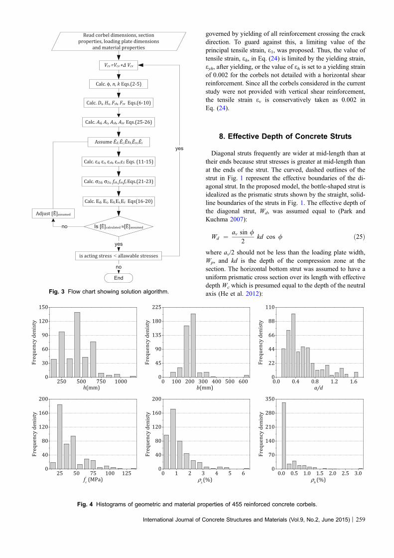
Read corbel dimensions, section
properties, loading plate dimensions
and material properties
Calc. φ, n, k Eqs.(2-5)
Calc. Ds, Hc, Fsh, Fsv Eqs.(6-10)
Calc. Ad, Ac, Ash, Asv Eqs.(25-26)
Calc. εd, εc, εsh, εsv,εS Eqs. (11-15)
Vcv =Vcv + Vcv
Calc. σ2d, σ2c, fsh, fsv,fs Eqs.(21-23)
Assume d, c, h, sv, s
Calc. Εd, Εc, Εh,Εv,Εs Eqs(16-20)
Is [ ]calculated [ ]assumed
Adjust [ ]assumed
no
is acting stress < allawable stresses
yes
yes
End
no
Fig. 3 Flow chart showing solution algorithm.
250 500 750 10000
30
60
90
120
150
Fre
qu
en
cy d
en
isty
h(mm)0 100 200 300 400 500 600
0
45
90
135
180
225
Fre
qu
en
cy d
en
isty
b(mm)0.0 0.4 0.8 1.2 1.60
22
44
66
88
110
Fre
qu
en
cy d
en
isty
a/d
25 50 75 100 1250
40
80
120
160
200
Fre
qu
en
cy d
en
isty
f`c (MPa)
0 1 2 3 4 5 60
40
80
120
160
200
Fre
qu
en
cy d
en
isty
ρs (%)0.0 0.5 1.0 1.5 2.0 2.5 3.0
0
70
140
210
280
350
Fre
qu
en
cy d
en
isty
ρh (%)
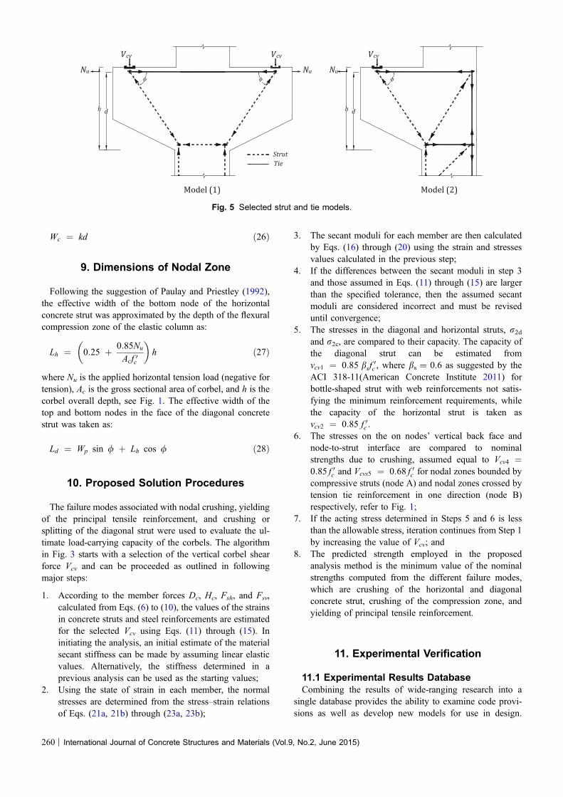
Fig. 4 Histograms of geometric and material properties of 455 reinforced concrete corbels.
International Journal of Concrete Structures and Materials (Vol.9, No.2, June 2015) | 259
Wc ¼ kd ð26Þ
9. Dimensions of Nodal Zone
Following the suggestion of Paulay and Priestley (1992),the effective width of the bottom node of the horizontalconcrete strut was approximated by the depth of the flexuralcompression zone of the elastic column as:
Lh ¼ 0:25 þ 0:85Nu
Acf 0c
� �h ð27Þ
where Nu is the applied horizontal tension load (negative fortension), Ac is the gross sectional area of corbel, and h is thecorbel overall depth, see Fig. 1. The effective width of thetop and bottom nodes in the face of the diagonal concretestrut was taken as:
Ld ¼ Wp sin / þ Lh cos / ð28Þ
10. Proposed Solution Procedures
The failure modes associated with nodal crushing, yieldingof the principal tensile reinforcement, and crushing orsplitting of the diagonal strut were used to evaluate the ul-timate load-carrying capacity of the corbels. The algorithmin Fig. 3 starts with a selection of the vertical corbel shearforce Vcv and can be proceeded as outlined in followingmajor steps:
1. According to the member forces Dc, Hc, Fsh, and Fsv,calculated from Eqs. (6) to (10), the values of the strainsin concrete struts and steel reinforcements are estimatedfor the selected Vcv using Eqs. (11) through (15). Ininitiating the analysis, an initial estimate of the materialsecant stiffness can be made by assuming linear elasticvalues. Alternatively, the stiffness determined in aprevious analysis can be used as the starting values;
2. Using the state of strain in each member, the normalstresses are determined from the stress–strain relationsof Eqs. (21a, 21b) through (23a, 23b);
3. The secant moduli for each member are then calculatedby Eqs. (16) through (20) using the strain and stressesvalues calculated in the previous step;
4. If the differences between the secant moduli in step 3and those assumed in Eqs. (11) through (15) are largerthan the specified tolerance, then the assumed secantmoduli are considered incorrect and must be reviseduntil convergence;
5. The stresses in the diagonal and horizontal struts, r2dand r2c, are compared to their capacity. The capacity ofthe diagonal strut can be estimated fromvcv1 ¼ 0:85 bsf
0c , where bs = 0.6 as suggested by the
ACI 318-11(American Concrete Institute 2011) forbottle-shaped strut with web reinforcements not satis-fying the minimum reinforcement requirements, whilethe capacity of the horizontal strut is taken asvcv2 ¼ 0:85 f 0c .
6. The stresses on the on nodes’ vertical back face andnode-to-strut interface are compared to nominalstrengths due to crushing, assumed equal to Vcv4 ¼0:85 f 0c and Vcvs5 ¼ 0:68 f 0c for nodal zones bounded bycompressive struts (node A) and nodal zones crossed bytension tie reinforcement in one direction (node B)respectively, refer to Fig. 1;
7. If the acting stress determined in Steps 5 and 6 is lessthan the allowable stress, iteration continues from Step 1by increasing the value of Vcv; and
8. The predicted strength employed in the proposedanalysis method is the minimum value of the nominalstrengths computed from the different failure modes,which are crushing of the horizontal and diagonalconcrete strut, crushing of the compression zone, andyielding of principal tensile reinforcement.
11. Experimental Verification
11.1 Experimental Results DatabaseCombining the results of wide-ranging research into a
single database provides the ability to examine code provi-sions as well as develop new models for use in design.
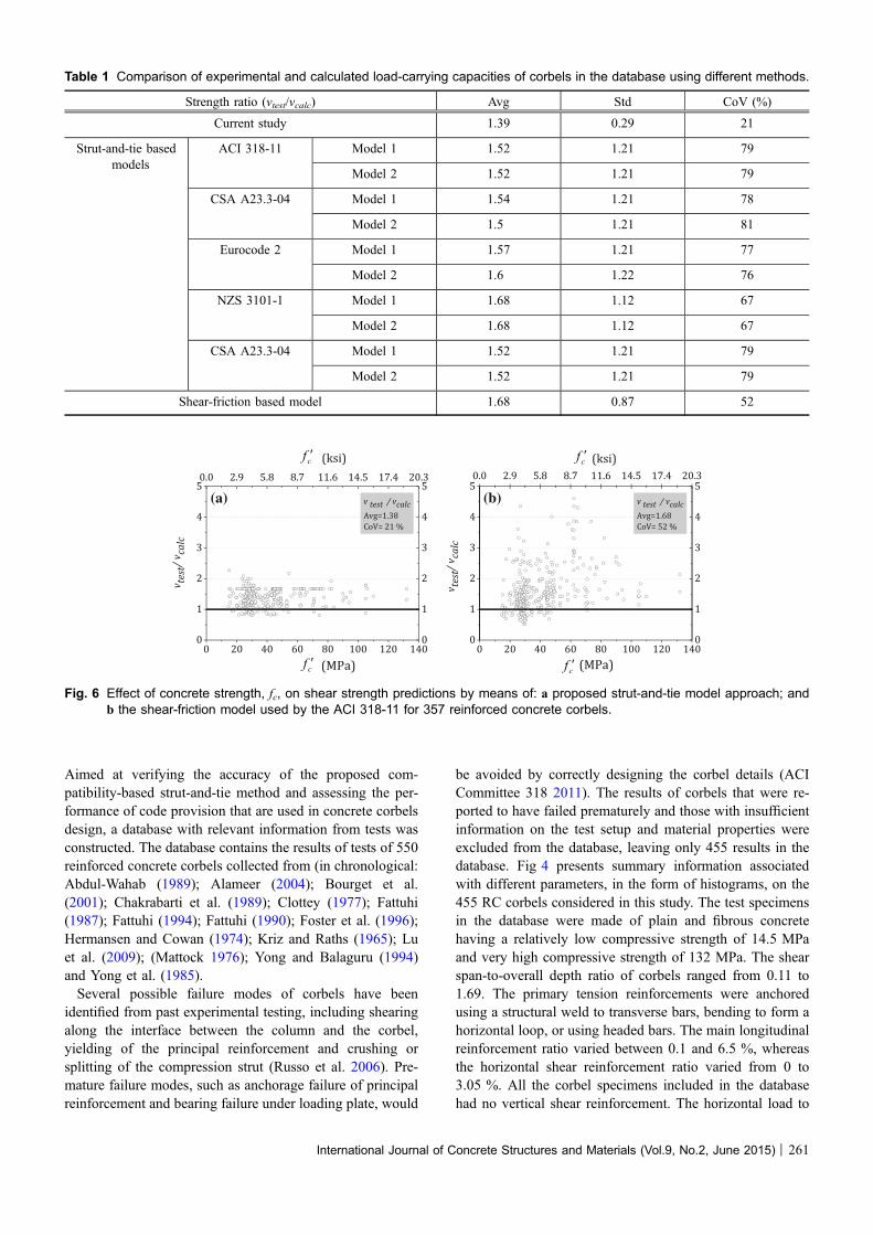
Fig. 5 Selected strut and tie models.
260 | International Journal of Concrete Structures and Materials (Vol.9, No.2, June 2015)
Aimed at verifying the accuracy of the proposed com-patibility-based strut-and-tie method and assessing the per-formance of code provision that are used in concrete corbelsdesign, a database with relevant information from tests wasconstructed. The database contains the results of tests of 550reinforced concrete corbels collected from (in chronological:Abdul-Wahab (1989); Alameer (2004); Bourget et al.(2001); Chakrabarti et al. (1989); Clottey (1977); Fattuhi(1987); Fattuhi (1994); Fattuhi (1990); Foster et al. (1996);Hermansen and Cowan (1974); Kriz and Raths (1965); Luet al. (2009); (Mattock 1976); Yong and Balaguru (1994)and Yong et al. (1985).Several possible failure modes of corbels have been
identified from past experimental testing, including shearingalong the interface between the column and the corbel,yielding of the principal reinforcement and crushing orsplitting of the compression strut (Russo et al. 2006). Pre-mature failure modes, such as anchorage failure of principalreinforcement and bearing failure under loading plate, would
be avoided by correctly designing the corbel details (ACICommittee 318 2011). The results of corbels that were re-ported to have failed prematurely and those with insufficientinformation on the test setup and material properties wereexcluded from the database, leaving only 455 results in thedatabase. Fig 4 presents summary information associatedwith different parameters, in the form of histograms, on the455 RC corbels considered in this study. The test specimensin the database were made of plain and fibrous concretehaving a relatively low compressive strength of 14.5 MPaand very high compressive strength of 132 MPa. The shearspan-to-overall depth ratio of corbels ranged from 0.11 to1.69. The primary tension reinforcements were anchoredusing a structural weld to transverse bars, bending to form ahorizontal loop, or using headed bars. The main longitudinalreinforcement ratio varied between 0.1 and 6.5 %, whereasthe horizontal shear reinforcement ratio varied from 0 to3.05 %. All the corbel specimens included in the databasehad no vertical shear reinforcement. The horizontal load to
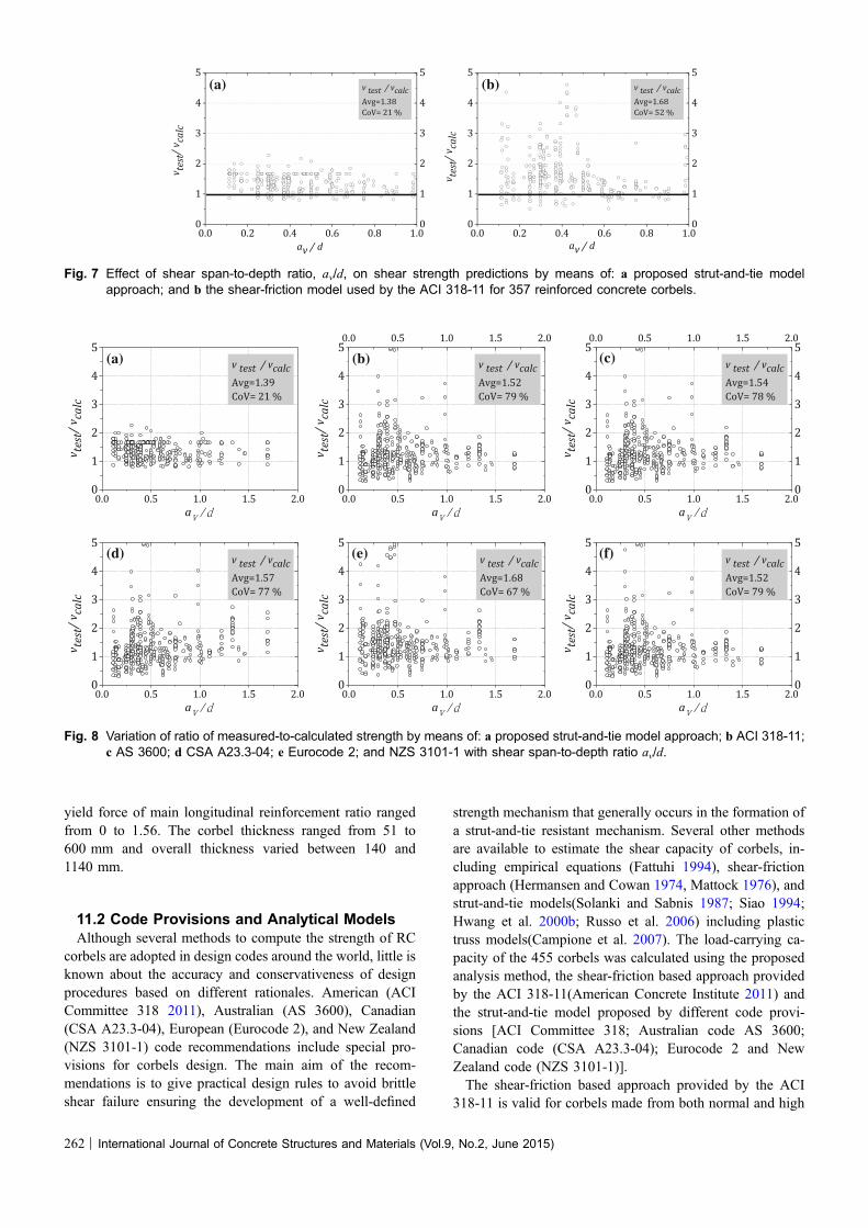
Table 1 Comparison of experimental and calculated load-carrying capacities of corbels in the database using different methods.
Strength ratio (vtest/vcalc) Avg Std CoV (%)
Current study 1.39 0.29 21
Strut-and-tie basedmodels
ACI 318-11 Model 1 1.52 1.21 79
Model 2 1.52 1.21 79
CSA A23.3-04 Model 1 1.54 1.21 78
Model 2 1.5 1.21 81
Eurocode 2 Model 1 1.57 1.21 77
Model 2 1.6 1.22 76
NZS 3101-1 Model 1 1.68 1.12 67
Model 2 1.68 1.12 67
CSA A23.3-04 Model 1 1.52 1.21 79
Model 2 1.52 1.21 79
Shear-friction based model 1.68 0.87 52
(a) (b)
Fig. 6 Effect of concrete strength, fc, on shear strength predictions by means of: a proposed strut-and-tie model approach; andb the shear-friction model used by the ACI 318-11 for 357 reinforced concrete corbels.
International Journal of Concrete Structures and Materials (Vol.9, No.2, June 2015) | 261
yield force of main longitudinal reinforcement ratio rangedfrom 0 to 1.56. The corbel thickness ranged from 51 to600 mm and overall thickness varied between 140 and1140 mm.
11.2 Code Provisions and Analytical ModelsAlthough several methods to compute the strength of RC
corbels are adopted in design codes around the world, little isknown about the accuracy and conservativeness of designprocedures based on different rationales. American (ACICommittee 318 2011), Australian (AS 3600), Canadian(CSA A23.3-04), European (Eurocode 2), and New Zealand(NZS 3101-1) code recommendations include special pro-visions for corbels design. The main aim of the recom-mendations is to give practical design rules to avoid brittleshear failure ensuring the development of a well-defined
strength mechanism that generally occurs in the formation ofa strut-and-tie resistant mechanism. Several other methodsare available to estimate the shear capacity of corbels, in-cluding empirical equations (Fattuhi 1994), shear-frictionapproach (Hermansen and Cowan 1974, Mattock 1976), andstrut-and-tie models(Solanki and Sabnis 1987; Siao 1994;Hwang et al. 2000b; Russo et al. 2006) including plastictruss models(Campione et al. 2007). The load-carrying ca-pacity of the 455 corbels was calculated using the proposedanalysis method, the shear-friction based approach providedby the ACI 318-11(American Concrete Institute 2011) andthe strut-and-tie model proposed by different code provi-sions [ACI Committee 318; Australian code AS 3600;Canadian code (CSA A23.3-04); Eurocode 2 and NewZealand code (NZS 3101-1)].The shear-friction based approach provided by the ACI
318-11 is valid for corbels made from both normal and high
(a) (b)
Fig. 7 Effect of shear span-to-depth ratio, av/d, on shear strength predictions by means of: a proposed strut-and-tie modelapproach; and b the shear-friction model used by the ACI 318-11 for 357 reinforced concrete corbels.
(a) (b)
(d) (e) (f)
(c)
Fig. 8 Variation of ratio of measured-to-calculated strength by means of: a proposed strut-and-tie model approach; b ACI 318-11;c AS 3600; d CSA A23.3-04; e Eurocode 2; and NZS 3101-1 with shear span-to-depth ratio av/d.
262 | International Journal of Concrete Structures and Materials (Vol.9, No.2, June 2015)
strength concrete with span-to-depth ratio less than unity.This procedure refers to two typical modes of failure: thefirst is the failure mode due to shear constraint occurring atthe interface between column and corbel, and which occurswith very small shear-span ratios and reduced percentages ofreinforcement. For a shear failure, the shear strength of acorbel is given by:
Vcv ¼ qvf fys l b d ð29Þ
where qvf = (qs ? qh) is the frictional reinforcement ratio;fys is the yield strength of the friction reinforcement; qs andqh is the principal reinforcement ratio and horizontal webreinforcement ratio, respectively; l is the coefficient offriction (taken as 1.4 for monolithic construction); and b isthe corbel width. The second mode of failure is due toflexural yielding of the principal longitudinal reinforcement,and the carrying capacity can be estimated as:
Vcv ¼ qsfyjd½avð1 þ aðh � dÞÞ� bd ð30Þ
where a is the horizontal-to-vertical loads ratio; and jd is thelever arm calculated by jd ¼ d � ðAsfys � NuÞ
0:88 f 0c b. The corbel
strength is taken as the minimum value of Eqs. (29) and (30).Moreover, the code imposes an upper limit on the load-carrying capacity with a maximum value of Vcv shall notexceed the smallest of 0:2f 0c bd; ð3:3 þ 0:08 f 0c Þbd and 11 bd:
Several code recommendations (CSA Committee A23.32004, NZS 3101 2006) specify the strut-and-tie models forthe design of corbels, while only for corbels having shearspan-to-depth ratio greater than 1.0, the ACI 318-11 rec-ommends the use of a strut-and-tie model described in ACI318-11, Appendix A. However, it does not provide detailedguidance on strut-and-tie models for different cases. It iswell known that in using the strut-and-tie model, the de-signer is free to select the form and dimensions of the load-resisting truss to transfer the applied forces to the supports.More than one strut-and-tie model is usually feasible andthus there is no unique design solution as there typically iswith the use of the conventional sectional design procedures.The safety of the strut-and tie model approach is highlydependent on the suitability of the assumption in lower-bound plasticity theory that the structure is adequatelyductile to allow the load to be supported in the way chosenby the designer.The experimental results are compared with predictions
made on the basis of a simplified strut-and-tie model (STM)accounting for the main tie steel only, a refined strut-and-tiemodel accounting for the secondary crack-control rein-forcement (Reineck 2003). These two models were reportedto be very conservative and assume corbels failure are due toyielding of the tie and/or horizontal web reinforcement, thusprevent the assessment of codes provisions (Yang et al.2012). Instead, two strut-and-tie models for a double-sidedcorbel and a single corbel projected from a column shown inFig. 5, are proposed and it is assumed corbel failure is due to
(a)
(d) (e)
(b) (c)
(f)
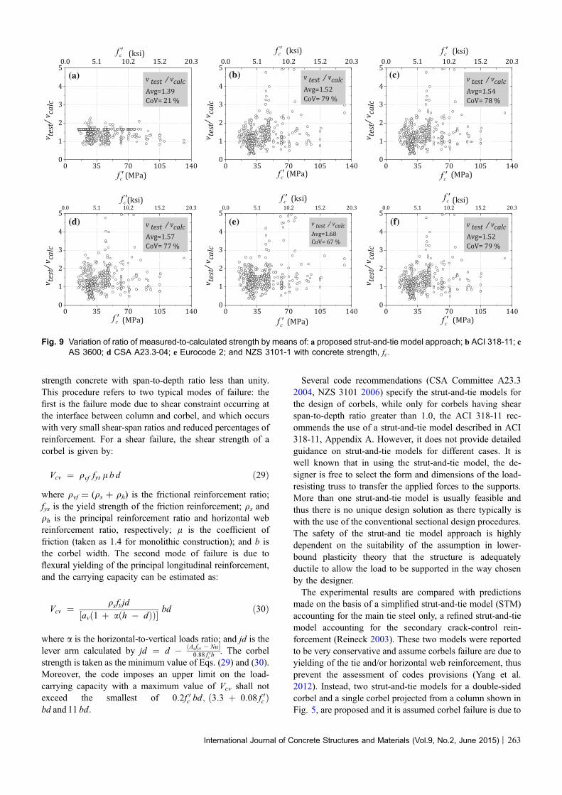
Fig. 9 Variation of ratio of measured-to-calculated strength by means of: a proposed strut-and-tie model approach; b ACI 318-11; cAS 3600; d CSA A23.3-04; e Eurocode 2; and NZS 3101-1 with concrete strength, fc:
International Journal of Concrete Structures and Materials (Vol.9, No.2, June 2015) | 263
either crushing of the horizontal and diagonal concrete strut,crushing of the compression zone, or yielding of principaltensile reinforcement, similar to that assumed in the pro-posed strut-and-tie based method.
11.3 Comparison of Load-Carrying CapacityVery few studies found in the literature on the validity of
load-carrying capacity models of RC corbels in code pro-visions including strut-and-tie models. Table 1 summarizesthe average, Avg, standard deviation, SD, and coefficient ofvariation, CoV, of the ratio between measured and calculatedcapacities, vtest/vcalc, of RC corbels considered, based on theproposed strut-and-tie based method, the shear-friction basedapproach provided by the ACI 318-11, the strut-and-tiemodel proposed by five codes of practice examined (ACI318-11; (c) AS 3600; (d) CSA A23.3-04; (e) Eurocode 2;and NZS 3101-1). The distribution of average strength ratiosfor the specimens in the database against the concretestrength, f 0c , and shear span-to-depth ratio, av/d, is shown inFigs. 6, 7, 8 9, where Avg and CoV values are also reported.For the comparison with the shear-friction based approach
provided by the ACI 318-11, only 357 corbels with shearspan-to-depth ratio less than unity have been taken into ac-count. Careful examination of the results shows that theshear strength ratios, vtest/vcalc, using the shear-friction basedapproach provides highly conservative and scattered esti-mates of the strength of corbels over a wide range of con-crete strength and shear span-to-depth ratio. The coefficientof variation is quite high, with a value of 52 %, thus a low5 % fractile value is to be expected. Altogether, 51 testsexhibit unconservative estimations, which is remarkablymore than the 5 % fractile of 18 tests. Therefore, the resultsfrom this new database, which is much larger and morecomprehensive than that used to calibrate the shear-frictionbased approach of ACI 318-11 in the 1980s, are clearlyunsafe. In particular, the shear-friction based approach isunconservative in the prediction of the load-carrying ca-pacity for corbels with concrete strength less than 50 MPa,(see Fig. 6b). By contrast, the calculated capacities by theproposed strut-and tie based method are both accurate andconservative with low scatter or trends for RC corbels withshear-to-span depth ratios ranging from 0 to 1 (see Fig. 7a).The selected strut-and-tie models shown in Fig. 5 produce
results that are quite similar to each other, refer to Table 1.Figures 7 and 8 present the effect of shear span-to-depthratio, av/d, and concrete strength, f 0c on the load-carryingcapacity predictions of the strut-and-tie based method andthe five codes of practice examined for the double-sidedcorbel model only, respectively. On the whole, the predic-tions of the proposed method are very consistent for a broadrange of concrete strengths and shear span-to-depth ratio,indicating that Avg, SD and COV are 1.39, 0.29, and 21 %,respectively. On the other hand, the overall performances ofthe five codes of practice examined are very similar, highlyconservative and scattered. This conservatism may be at-tributed to the conservatism in the effective depth of thediagonal strut (Park and Kuchma 2007). They consistentlyunderestimate the load-carrying capacity of corbels with
concrete strength greater than 35 MPa and shear span-to-depth ratio greater than 0.3. The largest average of the shearstrength ratios, (vtest/vcalc) of all STM models appear asspecified in Eurocode 2. The size of this test database andthe use of these five code provisions are enough to obtainvaluable insight into the behaviour of RC corbels from a strut-and-tie perspective. Considering the width of the compileddatabase, the obtained results are considered to be adequatelyfair to suggest that the proposed strut-and-tie based methodprovides a reliable and safe means of predicting the load-carrying capacity of reinforced concrete corbels.
12. Summary and Conclusions
A strut-and-tie based method intended for calculating theload-carrying capacity of reinforced concrete corbels hasbeen presented. In addition to the normal strut-and-tie forceequilibrium requirements, the proposed model accounts forstrain compatibility and stress–strain relationship of crackedreinforced concrete, and uses a secant stiffness formulation.Based on the available test results in the literature and theircomparison with the proposed model and the shear-frictionbased approach provided by the ACI 318 formulas as well asthe strut-and-tie provisions in the American, Canadian, NewZealand, Eurocode and Australian codes., the followingconclusions may be drawn:
1. The calculated load-carrying capacities by the proposedmethod were both accurate and conservative withlimited scatter or trends for reinforced concrete corbelswith shear span-to-depth ratios ranging from 0.1 to 2and made from normal or fibrous concrete.
2. The shear-friction based approach provided by theAmerican code is highly conservative and scatteredestimates of the strength of corbels over a wide range.By contrast, the calculated capacities by the proposedstrut-and tie based method are both accurate andconservative with low scatter or trends for RC corbelswith shear-to-span depth ratios ranging from 0 to 1.
3. The predictions by the proposed strut-and-tie basedmethod are adequately conservative and accurate toconclude that it provides a safe and reliable means ofcalculating the load-carrying capacity of concrete corbels.
4. Based on the conclusions drawn from this research, theproposed strut-and-tie should be adopted in futureadjustments to code provisions and in the developmentof design guidelines for all types of D-regions instructural concrete. Furthermore, both experimental andmathematical studies are still needed to investigate theapplicability and limitations of the proposed strut-and-tie method when applied to a wide range of D-regions.
Acknowledgment
The Author would like to thank Prof. Keun-Hyeok Yang,Kyonggi University, South Korea for providing some
264 | International Journal of Concrete Structures and Materials (Vol.9, No.2, June 2015)
information on tests of corbels and assistance in populatingthe corbels database.
Open Access
This article is distributed under the terms of the CreativeCommons Attribution 4.0 International License (http://creativecommons.org/licenses/by/4.0/), which permits un-restricted use, distribution, and reproduction in any medium,provided you give appropriate credit to the original author(s)and the source, provide a link to the Creative Commonslicense, and indicate if changes were made.
References
Abdul-Wahab, H. M. (1989). Strength of reinforced concrete
corbels with fibers. ACI Structural Journal, 86(1), 60–66.
Alameer, M. (2004). Effects of fibres and headed bars on the
response of concrete corbels. M SC thesis, Department of
Civil Engineering and Applied Mechanics, McGill
University, Montreal, Canada.
Ali, M., & White, R. (2001). Consideration of compression
stress bulging and strut degradation in truss modeling of
ductile and brittle corbels. Engineering Structures, 23(3),
240–249.
American Concrete Institute. (2011). Building Code Require-
ments for Structural Concrete (ACI 318-11) and Com-
mentary (ACI 318R-11). Farmington Hills, MI: ACI.
Australian code AS 3600. (2009). Australian Standard for
Concrete Structures (p. 213). North Sydney, Australia:
Standards Australia.
Bourget, M., Delmas, Y., & Toutlememonde, F. (2001). Ex-
perimental study of the behaviour of reinforced high-
strength concrete short corbels. Materials and Structures,
34(3), 155–162.
British Standards Institution. (2004). Eurocode 2: Design of
concrete structures—Part 1–1: General rules and rules for
buildings. London, UK: British Standards Institution.
Campione, G., La Mendola, L., & Mangiavillano, M. L. (2007).
Steel fiber-reinforced concrete corbels: Experimental be-
havior and shear strength prediction. ACI Structural Jour-
nal, 104(5), 570–579.
Chakrabarti, P. R., Farahi, D. J., & Kashou, S. I. (1989). Re-
inforced and precompressed concrete corbels-an ex-
perimental study. ACI Structural Journal, 86(4), 132–142.
Clottey, C. (1977). Performance of lightweight concrete corbels
subjected to static and repeated loads. PhD thesis, Okla-
homa State University, Ann Arbor, MI, pp. 127–127.
CSA Committee A23.3. (2004). Design of concrete structures.
Mississauga, Canada: Canadian Standard Association 232.
Fattuhi, N. (1987). SFRC corbel tests. ACI Structural Journal,
84(2), 119–123.
Fattuhi, N. (1990). Strength of SFRC corbels subjected to ver-
tical load. Journal of Structural Engineering, 116(3),
701–718.
Fattuhi, N. (1994). Reinforced corbels made with plain and
fibrous concretes. ACI Structural Journal, 91(5), 530–536.
Foster, S. J., Powell, R. E., & Selim, H. S. (1996). Performance
of high-strength concrete corbels. ACI Structural Journal,
93(5), 555–563.
He, Z.-Q., Liu, Z., & Ma, Z. J. (2012). Investigation of load-
transfer mechanisms in deep beams and corbels. ACI
Structural Journal, 109(4), 467–476.
Hermansen, B. R., & Cowan, J. (1974). Modified shear-friction
theory for bracket design. ACI Journal Proceedings, 71(2),
55–60.
Hwang, S.-J., Fang, W.-H., Lee, H.-J., & Yu, H.-W. (2001).
Analytical model for predicting shear strength of squat
walls. Journal of Structutral Engineering, ASCE, 127(1),
43–50.
Hwang, S.-J., & Lee, H.-J. (1999). Analytical model for pre-
dicting shear strengths of exterior reinforced concrete
beam-column joints for seismic resistance. ACI Structural
Journal, 96(5), 846–857.
Hwang, S.-J., & Lee, H.-J. (2000). Analytical model for pre-
dicting shear strengths of interior reinforced concrete beam-
column joints for seismic resistance. ACI Structural Jour-
nal, 97(1), 35–44.
Hwang, S.-J., & Lee, H.-J. (2002). Strength prediction for dis-
continuity regions by softened strut-and-tie model. Journal
of Structural Engineering, 128(12), 1519–1526.
Hwang, S.-J., Lu, W.-Y., & Lee, H.-J. (2000a). Shear strength
prediction for deep beams. ACI Structural Journal, 97(3),
367–376.
Hwang, S.-J., Lu, W.-Y., & Lee, H.-J. (2000b). Shear strength
prediction for reinforced concrete corbels. ACI Structural
Journal, 97(4), 543–552.
Kriz, L. B., & Raths, C. H. (1965). Connections in precast
concrete structures—Strength of corbels. PCI Journal,
10(1), 16–61.
Lu, W.-Y., Lin, I.-J., & Hwang, S.-J. (2009). Shear strength of
reinforced concrete corbels. Magazine of Concrete Re-
search, 61(10), 807–813.
Lu, W. Y., Lin, I. J., Hwang, S. J., & Lin, Y. H. (2003). Shear
strength of high-strength concrete dapped-end beams. Journal
of the Chinese Institute of Engineers, 26(5), 671–680.
MacGregor, J., & Wight, J. (2009). Reinforced concrete: Me-
chanics and design. Singapore: Prentice Hall and Pearson
Education South Asia.
Mattock, A. H. (1976). Design proposals for reinforced concrete
corbels. PCI Journal, 21(3), 18–42.
NZS 3101. (2006). Part 1: Code of practice for the design of
concrete structures and Part 2: Commentary on the design
of concrete structures. Wellington, New Zealand: Standards
Association of New Zealand.
Park, J., & Kuchma, D. (2007). Strut-and-tie model analysis for
strength prediction of deep beams. ACI Structural Journal,
104(6), 657–666.
Paulay, T., & Priestley, M. (1992). Seismic design of reinforced
concrete and masonry buildings. New York, NY: Wiley.
Reineck, K. (2003). Examples for the design of structural
concrete with strut-and-tie models. ACI International, SP-
208, 128–141.
International Journal of Concrete Structures and Materials (Vol.9, No.2, June 2015) | 265
Russo, G., Venir, R., Pauletta, M., & Somma, G. (2006). Re-
inforced concrete corbels-shear strength model and design
formula. ACI Materials Journal, 103(1), 3–10.
Schlaich, J., Schafer, K., & Jennewein, M. (1987). Toward a
consistent design of structural concrete. PCI Journal, 32(3),
74–150.
Siao, W. B. (1994). Shear strength of short reinforced concrete
walls, corbels, and deep beams. ACI Structural Journal,
91(2), 123–132.
Solanki, H., & Sabnis, G. M. (1987). Reinforced concrete
corbels-simplified. ACI Structural Journal, 84(5), 428–432.
Vecchio, F. J. (1989). Nonlinear finite element analysis of re-
inforced concrete membranes. ACI Structural Journal,
86(1), 26–35.
Vecchio, F. J., & Collins, M. P. (1993). Compression response
of cracked reinforced concrete. Journal of Structural
Engineering, 119(12), 3590–3610.
Yang, K.-H., & Ashour, A. F. (2012). Shear capacity of rein-
forced concrete corbels using mechanism analysis. Pro-
ceedings of the ICE-Structures and Buildings, 165(3),
111–125.
Yang, J., Lee, J., Yoon, Y., Cook, W., & Mitchell, D. (2012).
Influence of steel fibers and headed bars on the service-
ability of high-strength concrete corbels. Journal of
Structural Engineering, 138(1), 123–129.
Yong, Y., & Balaguru, P. (1994). Behavior of reinforced high-
strength-concrete corbels. Journal of Structural Engineer-
ing, 120(4), 1182–1201.
Yong, Y., McCloskey, D. H., & Nawy, E. G. (1985). Reinforced
corbels of high-strength concrete. London, UK: ACI Spe-
cial Publication. 87.
266 | International Journal of Concrete Structures and Materials (Vol.9, No.2, June 2015)