Embed Size (px)
Citation preview

Strength of Materials 1 Lecture 1 Dr. Ali Ajaam
1
Strength of Materials Ⅰ
References:
1- Mechanics of Materials By R. C. Hibbeler
2- Strength of Materials By Pytel and Singer
3- Introduction to Mechanics of Solids By Popove
Syllabus (course 1)
1- Average Normal Stress
2- Average Shear and bearing Stress
3- Strain and Stress-Strain Relations
4- Axial Load
5- Thermal Stresses
6- Torsion
7- Shear Force and Bending Moment diagram
8- Stresses in Beams
Course Layout
Exam 1 Exam 2 Quizzes &
Assignments
Attendance Laboratory Final
15 15 5 5 10 50

Strength of Materials 1 Lecture 1 Dr. Ali Ajaam
2
Statics
Equilibrium of Deformable Body
Some of the main principles of static are reviewed in this section
External loads:
Figure 1 Types of external loads

Strength of Materials 1 Lecture 1 Dr. Ali Ajaam
3
1. Surface forces are caused by the direct contact of one body with the surface
of another. In all cases the forces are distributed over the area of contact,
which results in three types of loads: Concentrated force when the area of
contact is too small compared to the total surface area (Ex. Force of ground
on a wheel of a bicycle), Linear distributed load when the contact area is a
narrow strip of the body (Ex. Load along the length of a beam),
2. Body Force is developed when one body exerts a force on another body
without a direct physical contact (Ex. Gravity force, weight)
Support Reactions: (as shown in Table 1)
Table 1 Types of support reactions

Strength of Materials 1 Lecture 1 Dr. Ali Ajaam
4
Equation of Equilibrium
Equilibrium of a body requires both a balance of forces (to prevent movement)
and a balance of moments (to prevent rotation). Mathematically, these two
conditions can be expressed as:
∑ (Summation of all forces acting on the body)
∑ (Summation of the moments of all forces about any poit)
When the (x, y, z) coordinate of the system are established, the forces and moment
vectors can be resolve into components along each coordinate axis, as below:
∑ ∑ ∑
∑ ∑ ∑
The best way to account for all these forces is draw the free-body diagram of the
system.
Internal Resultant Loadings
To determine the Resultant loading that acts within a body, we use the principles of
statics by taking an imaginary cut on the specific region within the body. The exact
distribution of the internal loading may be unknown; we can use the principles of
equilibrium to find the resultants and the components. The four different types
components resultant loading can be defined as:

Strength of Materials 1 Lecture 1 Dr. Ali Ajaam
5
Normal force, N. it is a force perpendicular to the area and is developed when the
external loads tend to push or pull on the two segments of the body.
Shear force, V. the shear force lies in the plane of the area and it is developed
when the external loads tend to cause the two segments of the body to side over
one another.
Torsional moment or Torque, T. This effect is developed when external loads
tend to twist one segment of the body with respect to the other about an axis
perpendicular to the area.
Bending moment, M. it is caused by the external loads that tend to bend the body
about an axis lying within the plane of the area.

Strength of Materials 1 Lecture 1 Dr. Ali Ajaam
6
Stresses
Stress is the intensity of the internal forces acting on a specific area. Stress is
measured in Pascal in SI Unites (1 Pa = 1 N/m2) and in psi (pound per square inch)
in US Unites. In general stresses can be classified into:
Normal Stress is the intensity of the force acting normal to the area (σz) sigma, if
the normal force or stress pulls on the area then it referred to as tensile stress, and
if it pushes on the area it referred to as compressive stress.
Shear stress is the intensity of the force acting tangent to the area (τ) tau.
Bearing Stress is the intensity of stress that occurs at the contact presses between
two bodies.
Average Normal Stress
A prismatic bar (with a material approximated to be homogeneous and
isotropic) subjected to a force P passing through the centroid of its cross-section,
the bar will deform uniformly throughout the center region of its length. Hence, it
is necessary that the cross-section be subjected to a constant normal stress
distribution.

Strength of Materials 1 Lecture 1 Dr. Ali Ajaam
7
The general formula is
σ = average normal stress at any point on the cross-sectional area.
P = internal resultant normal force, which acts though the centroid of the cross-
sectional area.
A = cross-sectional area where σ is determined.
Problem 1
Compute the average normal stress in the two prismatic bars that are fixed at the
top points when subjected to the loading shown.
Solution
(
)
⁄
⁄
(constant through the bar length)
5 ton 5 ton
A1=2000 mm2
A2=200 mm2

Strength of Materials 1 Lecture 1 Dr. Ali Ajaam
8
⁄
Maximum Average Normal Stress
In Problem 1, the internal force P and the cross-section of the bars were constant
along the longitudinal axis, so the normal stress was also constant though the bar
length. Sometimes, the bar may be subjected to several external loads along its axis
and/or a change in its cross-sectional area. in such cases, to find the maximum
average normal stress, we should find the location where the ratio of P/A is
maximum.
Problem 2
The bar below has a constant width of 35 mm and a thickness of 10 mm. determine
the maximum average normal stress in the bar when it is subjected to the loading
shown.
Solution
Using the method of sections we find
the max. ratio of P/A
( )
( ) ( )

Strength of Materials 1 Lecture 1 Dr. Ali Ajaam
9
Problem 3
The 80 kg lamp is supported by two rods AB and BC as shown below. If AB has a
diameter of 10 mm and BC has a diameter of 8 mm, determine the average normal
stress in each rod.
Solution
First, draw the free-dody-diagram of the system
to find the exial force in each rod.
→ ∑ (
)
∑ (
)
( )
( )

Strength of Materials 1 Lecture 1 Dr. Ali Ajaam
10
Problem 4
The casting shown below is made of steel that have a specific weight of ℽst = 490
lb/ft3. Determine the average compressive stress acting on points A and B.
Solution
Draw a free-body-diagram of the top segment of the casting where the section
passes through points A and B. Then, Calculate the internal loading (weight of the
top segment)
∑ ,
( )( )[ ( ) ]⁄
Calculate the representative average compressive stress (stresses are the same in A
and B)
( ) ⁄
Strength of Materials 1 Lecture 1 Dr. Ali Ajaam
11
Problem 5
The Member AC is subjected to a vertical force of 3 KN. Determine the position x
of this force so that the average compressive stress at the smooth support C is equal
to the average tensile stress in the tie rod AB. The rod has across-sectional area of
400 mm2 and the contact area at C is 650 mm
2.
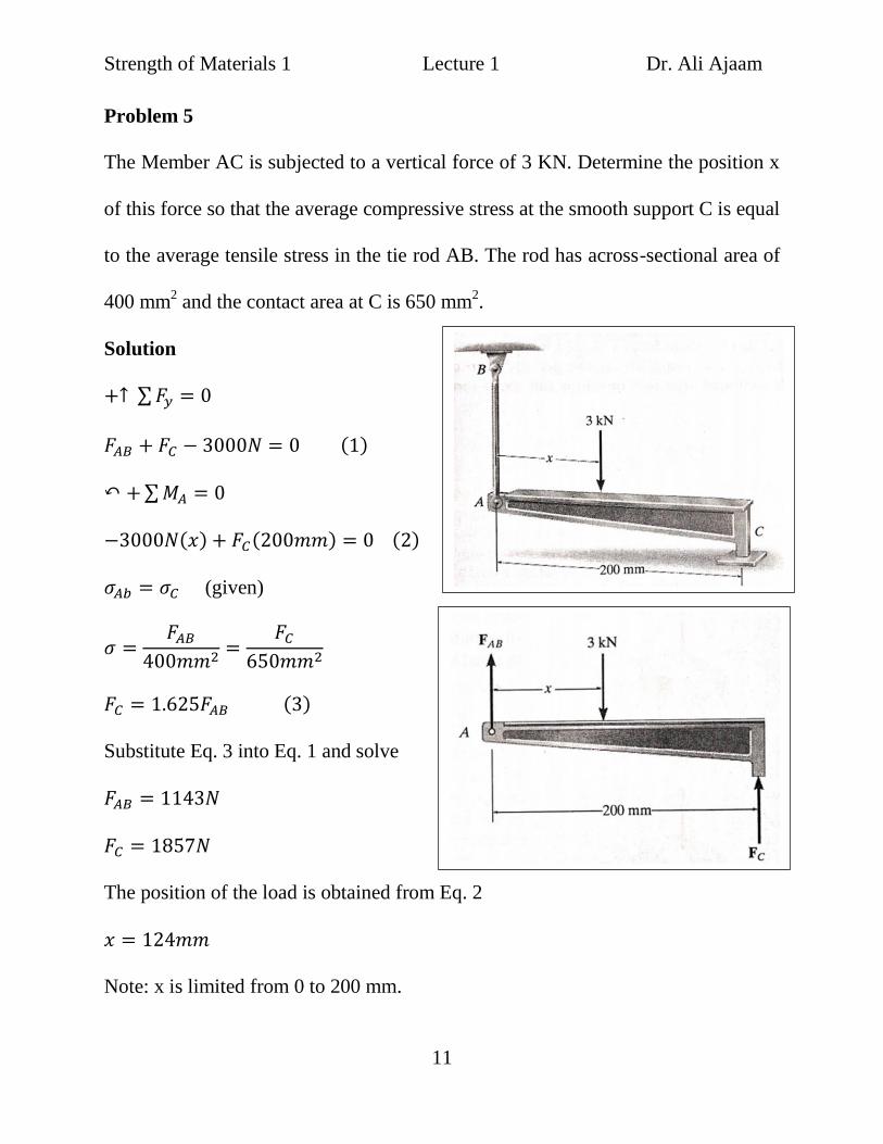
Solution
∑
( )
∑
( ) ( ) ( )
(given)
( )
Substitute Eq. 3 into Eq. 1 and solve
The position of the load is obtained from Eq. 2
Note: x is limited from 0 to 200 mm.

Strength of Materials 1 Lecture 1 Dr. Ali Ajaam
12
Homework
On your text solve problems (1.34, 1.35, 1.36, 1.46, and 1.47)