Embed Size (px)
Citation preview
University of Anbar College of Engineering Civil Engineering Department Iraq-Ramadi
Asst. Prof. Khalid R. Mahmood (PhD.)
322
Strength of different materials
Steel
Tensile strength
Concrete
Compressive strength
Soil
Shear strength
Presence of pore water
Complex
University of Anbar College of Engineering Civil Engineering Department Iraq-Ramadi
Asst. Prof. Khalid R. Mahmood (PhD.)
323
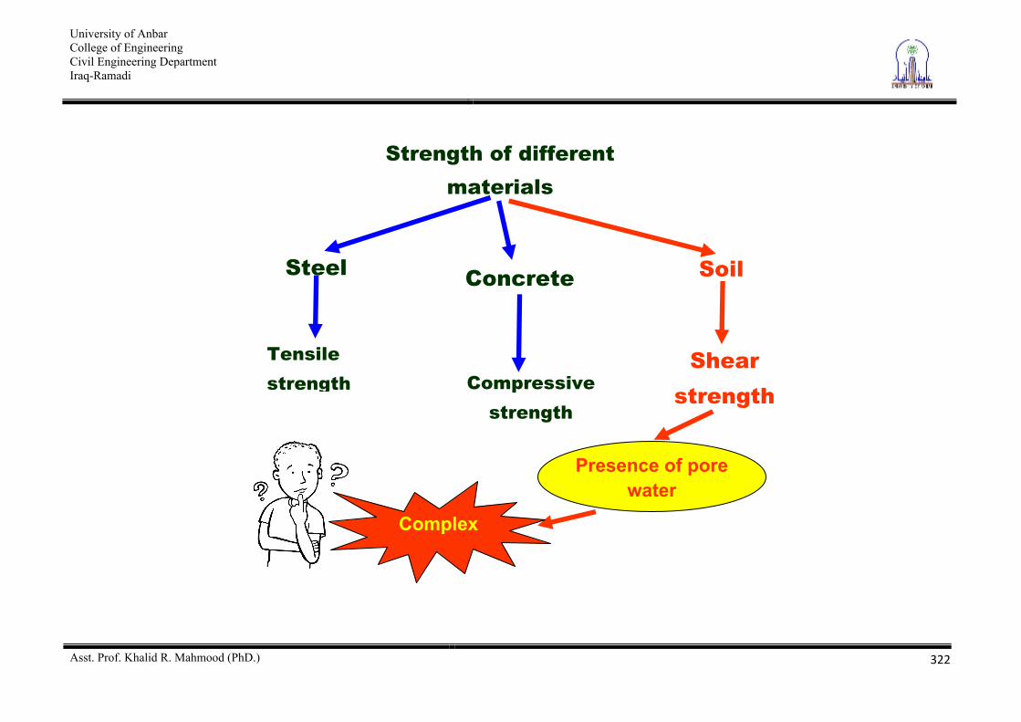
Shear Strength of Soils
Topics Introduction Mohr-Coulomb Failure Criterion Inclination of the plane of failure due to shear Determination of Shear Strength Parameters
1. Direct Shear test 2. Triaxial Shear tests
a. Consolidated-Drained (CD) Test b. Consolidated-Undrained (CU) Test c. Unconsolidated-Undrained (UU) Test
University of Anbar College of Engineering Civil Engineering Department Iraq-Ramadi
Asst. Prof. Khalid R. Mahmood (PhD.)
324
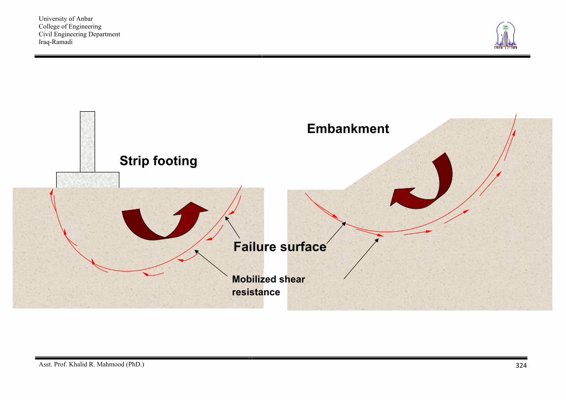
Strip footing
Embankment
Failure surface
Mobilized shear resistance
University of Anbar College of Engineering Civil Engineering Department Iraq-Ramadi
Asst. Prof. Khalid R. Mahmood (PhD.)
325
Introduction Soils are--
essentially frictional materials. are comprised of individual particles that can slide and roll
relative to one another, and it is generally assumed that the particles are not cemented.
Thus, the Shear strength of a soil mass is the internal resistance per unit area that the soil mass can offer to resist failure and sliding along any plane inside it.
University of Anbar College of Engineering Civil Engineering Department Iraq-Ramadi
Asst. Prof. Khalid R. Mahmood (PhD.)
326
One consequence of the frictional nature is that the strength depends on the effective stresses in the soil. As the effective stresses increase with depth, so in general will the strength. The strength will also depend on whether the soil deformation occurs under fully drained conditions, constant volume (undrained) conditions, or with some intermediate state of drainage. In each case, different excess pore pressures will occur resulting in different effective stresses, and hence different strengths. In assessing the stability of soil constructions analyses are usually performed to check the short term (undrained) and long term (fully drained) conditions.
University of Anbar College of Engineering Civil Engineering Department Iraq-Ramadi
Asst. Prof. Khalid R. Mahmood (PhD.)
327
Shear strength components The shear strength components are- Friction resistance- It occurs between the particles of the soil due to the external load consists of-
Friction due to sliding Friction due to rolling Friction due to interlocking
University of Anbar College of Engineering Civil Engineering Department Iraq-Ramadi
Asst. Prof. Khalid R. Mahmood (PhD.)
328
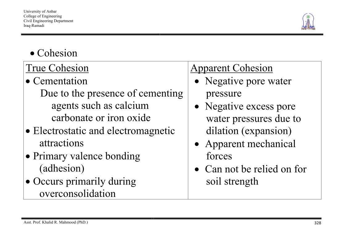
Cohesion True Cohesion Cementation
Due to the presence of cementing agents such as calcium carbonate or iron oxide
Electrostatic and electromagnetic attractions
Primary valence bonding (adhesion)
Occurs primarily during overconsolidation
Apparent Cohesion Negative pore water
pressure Negative excess pore
water pressures due to dilation (expansion)
Apparent mechanical forces
Can not be relied on for soil strength
University of Anbar College of Engineering Civil Engineering Department Iraq-Ramadi
Asst. Prof. Khalid R. Mahmood (PhD.)
329
Mohr-Coulomb Failure Criterion Mohr (1900) presented a theory for rupture in materials that held “a material fails through a critical combination of normal stress ( ) and shear resistance ( f ), and not through either maximum normal or shear stress alone. The functional relationship on a failure plane can be expressed in the form
)(ff In soils the relationship is approximated as a linear relationship as following
University of Anbar College of Engineering Civil Engineering Department Iraq-Ramadi
Asst. Prof. Khalid R. Mahmood (PhD.)
330
tancf This equation is known as the Mohr-Coulomb Failure Criterion. where c = cohesion, and
= angle of internal friction
University of Anbar College of Engineering Civil Engineering Department Iraq-Ramadi
Asst. Prof. Khalid R. Mahmood (PhD.)
331
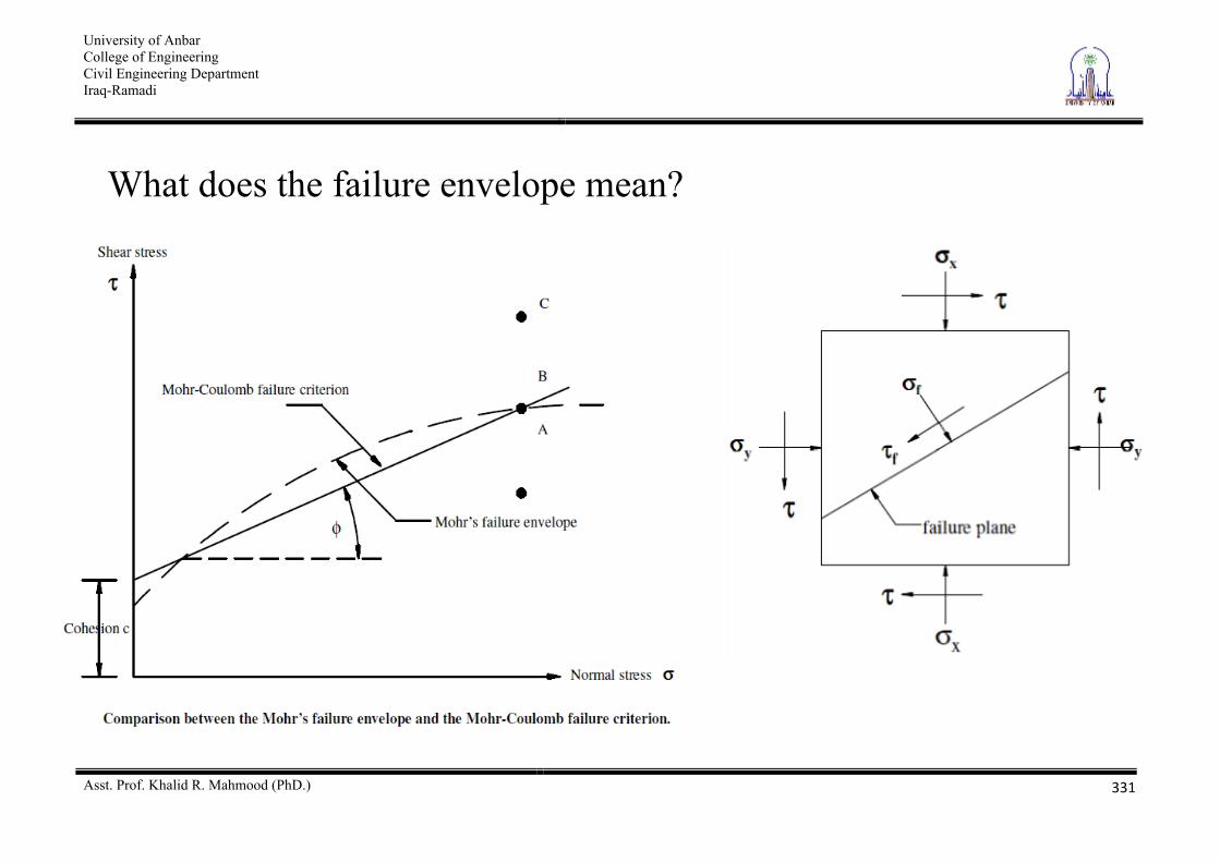
What does the failure envelope mean?
University of Anbar College of Engineering Civil Engineering Department Iraq-Ramadi
Asst. Prof. Khalid R. Mahmood (PhD.)
332
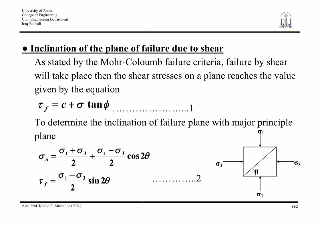
Inclination of the plane of failure due to shear As stated by the Mohr-Coloumb failure criteria, failure by shear will take place then the shear stresses on a plane reaches the value given by the equation
tancf …………………...1 To determine the inclination of failure plane with major principle plane
2sin2
2cos22
31
3131
f
n
…………..2
1
1
3 3
University of Anbar College of Engineering Civil Engineering Department Iraq-Ramadi
Asst. Prof. Khalid R. Mahmood (PhD.)
333
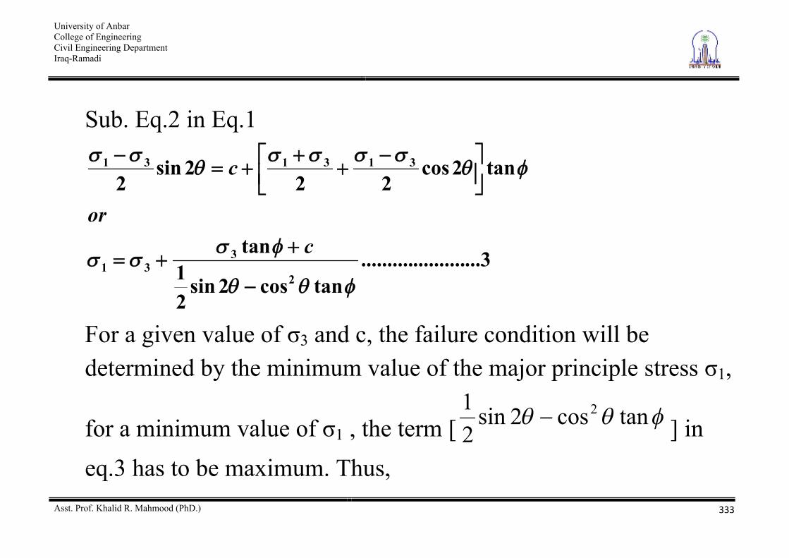
Sub. Eq.2 in Eq.1
3.......................tancos2sin
21
tan
tan2cos22
2sin2
2
331
313131
cor
c
For a given value of 3 and c, the failure condition will be determined by the minimum value of the major principle stress 1,
for a minimum value of 1 , the term [ tancos2sin21 2
] in eq.3 has to be maximum. Thus,
University of Anbar College of Engineering Civil Engineering Department Iraq-Ramadi
Asst. Prof. Khalid R. Mahmood (PhD.)
334
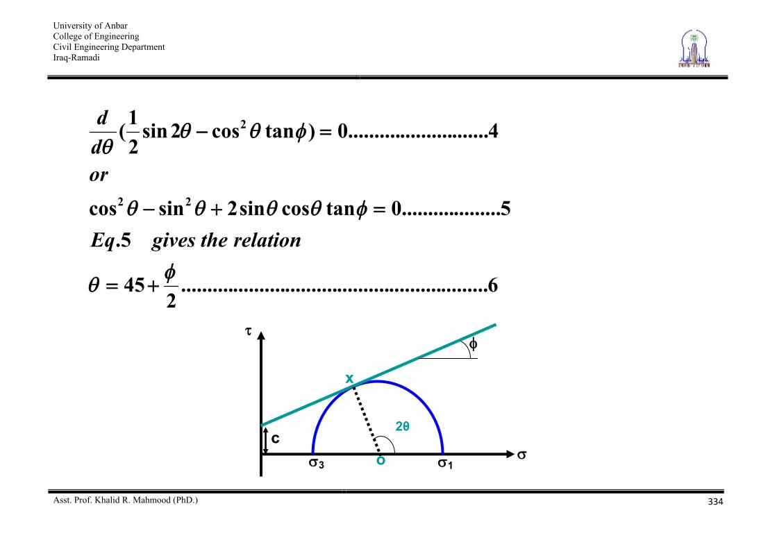
6...........................................................2
45
5.5...................0tancossin2sincos
4...........................0)tancos2sin21(
22
2
relationthegivesEq
ordd
3 1
x
c o
2
University of Anbar College of Engineering Civil Engineering Department Iraq-Ramadi
Asst. Prof. Khalid R. Mahmood (PhD.)
335
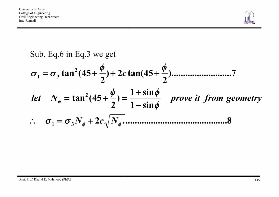
Sub. Eq.6 in Eq.3 we get
8.............................................2
sin1sin1)
245(tan
7.................).........2
45tan(2)2
45(tan
31
2
231
NcN
geometryfromitproveNlet
c
University of Anbar College of Engineering Civil Engineering Department Iraq-Ramadi
Asst. Prof. Khalid R. Mahmood (PhD.)
336
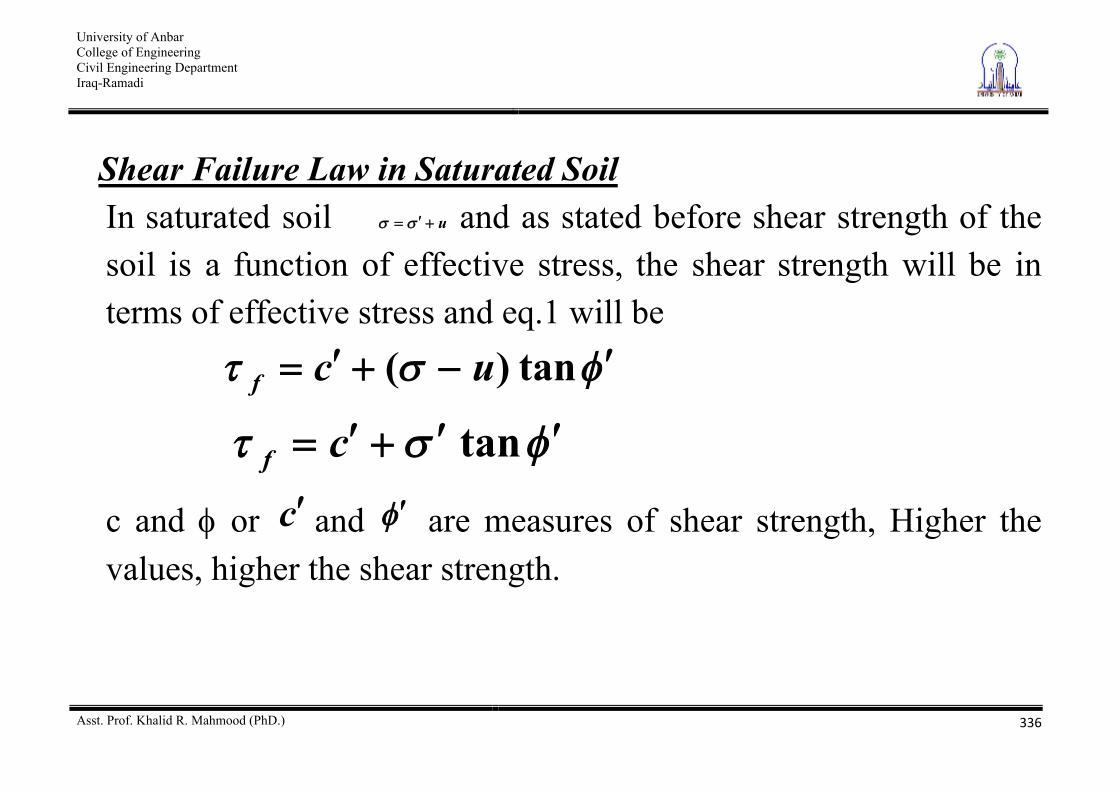
Shear Failure Law in Saturated Soil In saturated soil u and as stated before shear strength of the soil is a function of effective stress, the shear strength will be in terms of effective stress and eq.1 will be
tan)( ucf
tancf
c and or c and are measures of shear strength, Higher the values, higher the shear strength.
University of Anbar College of Engineering Civil Engineering Department Iraq-Ramadi
Asst. Prof. Khalid R. Mahmood (PhD.)
337
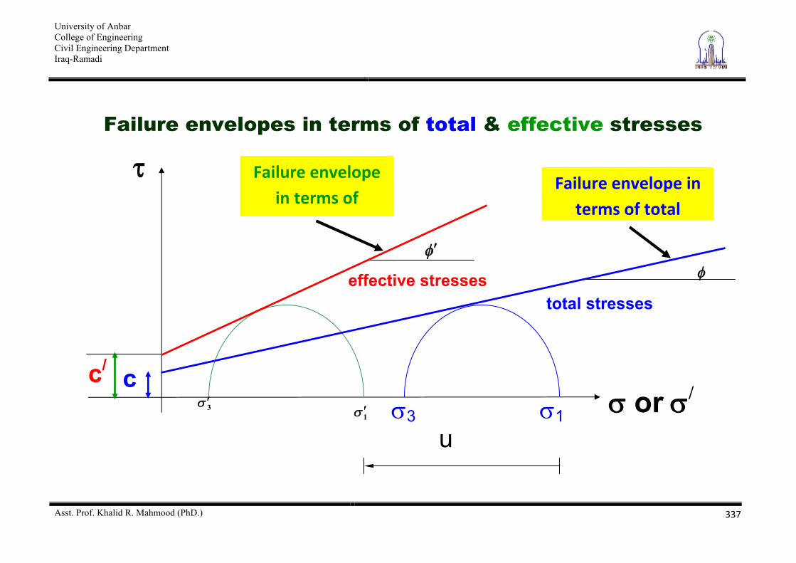
Failure envelopes in terms of total & effective stresses
1 3
total stresses
or / 1 3
effective stresses
u
c
Failure envelope in terms of total
c/
Failure envelope in terms of
effective stresses
University of Anbar College of Engineering Civil Engineering Department Iraq-Ramadi
Asst. Prof. Khalid R. Mahmood (PhD.)
338
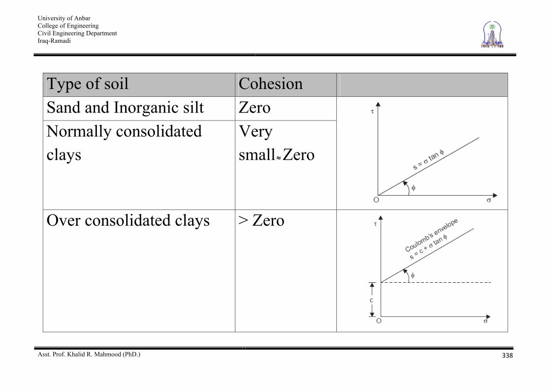
Type of soil Cohesion Sand and Inorganic silt Zero Normally consolidated clays
Very small Zero
Over consolidated clays > Zero
University of Anbar College of Engineering Civil Engineering Department Iraq-Ramadi
Asst. Prof. Khalid R. Mahmood (PhD.)
339
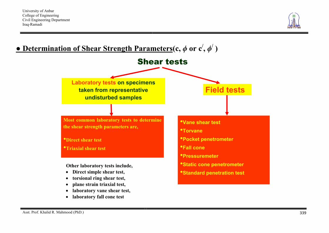
Determination of Shear Strength Parameters(c, or c/, / )
Other laboratory tests include, Direct simple shear test, torsional ring shear test, plane strain triaxial test, laboratory vane shear test, laboratory fall cone test
Shear tests
Laboratory tests on specimens taken from representative
undisturbed samples Field tests
Most common laboratory tests to determine the shear strength parameters are,
•Direct shear test
•Triaxial shear test
•Vane shear test •Torvane •Pocket penetrometer •Fall cone •Pressuremeter •Static cone penetrometer •Standard penetration test
University of Anbar College of Engineering Civil Engineering Department Iraq-Ramadi
Asst. Prof. Khalid R. Mahmood (PhD.)
340
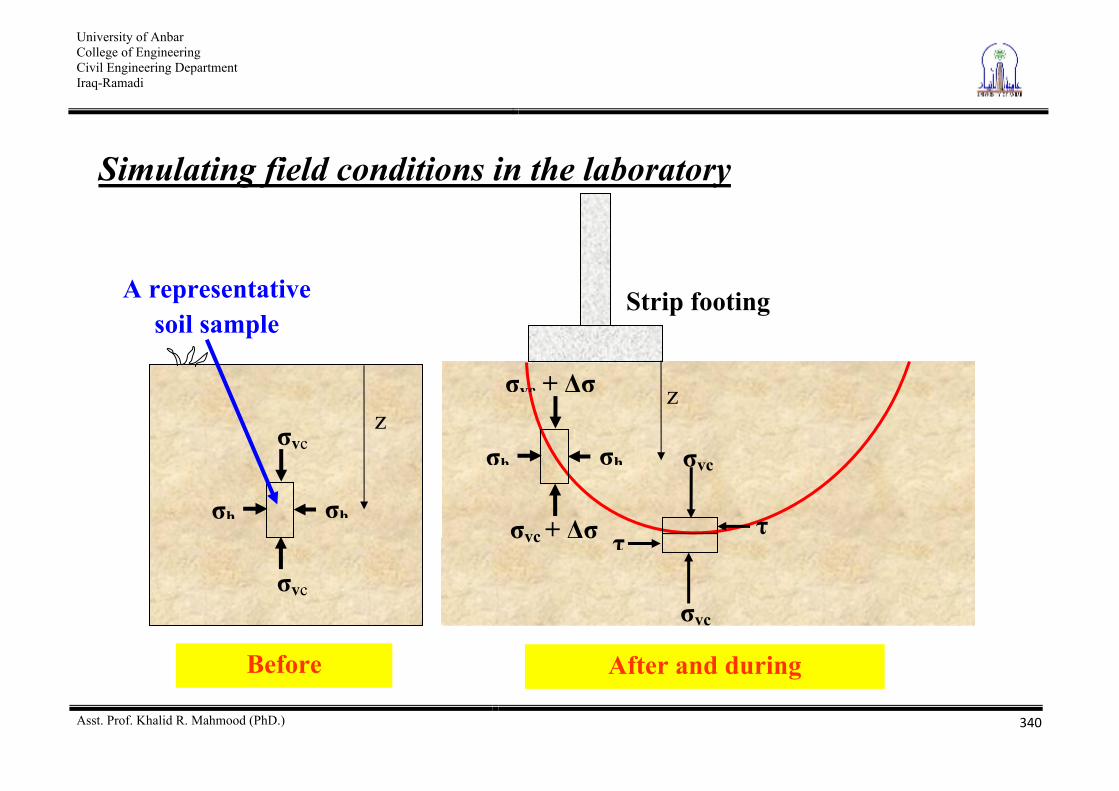
Simulating field conditions in the laboratory
z vc
vc
hh
Before
A representative soil sample
Strip footing
z vc +
vc +
hh
After and during
vc
vc
University of Anbar College of Engineering Civil Engineering Department Iraq-Ramadi
Asst. Prof. Khalid R. Mahmood (PhD.)
341
Step 1 Representative soil sample taken from the site Step 2 Set the specimen in the apparatus and apply the initial stress
condition Step 3 Apply the corresponding field stress conditions
University of Anbar College of Engineering Civil Engineering Department Iraq-Ramadi
Asst. Prof. Khalid R. Mahmood (PhD.)
342
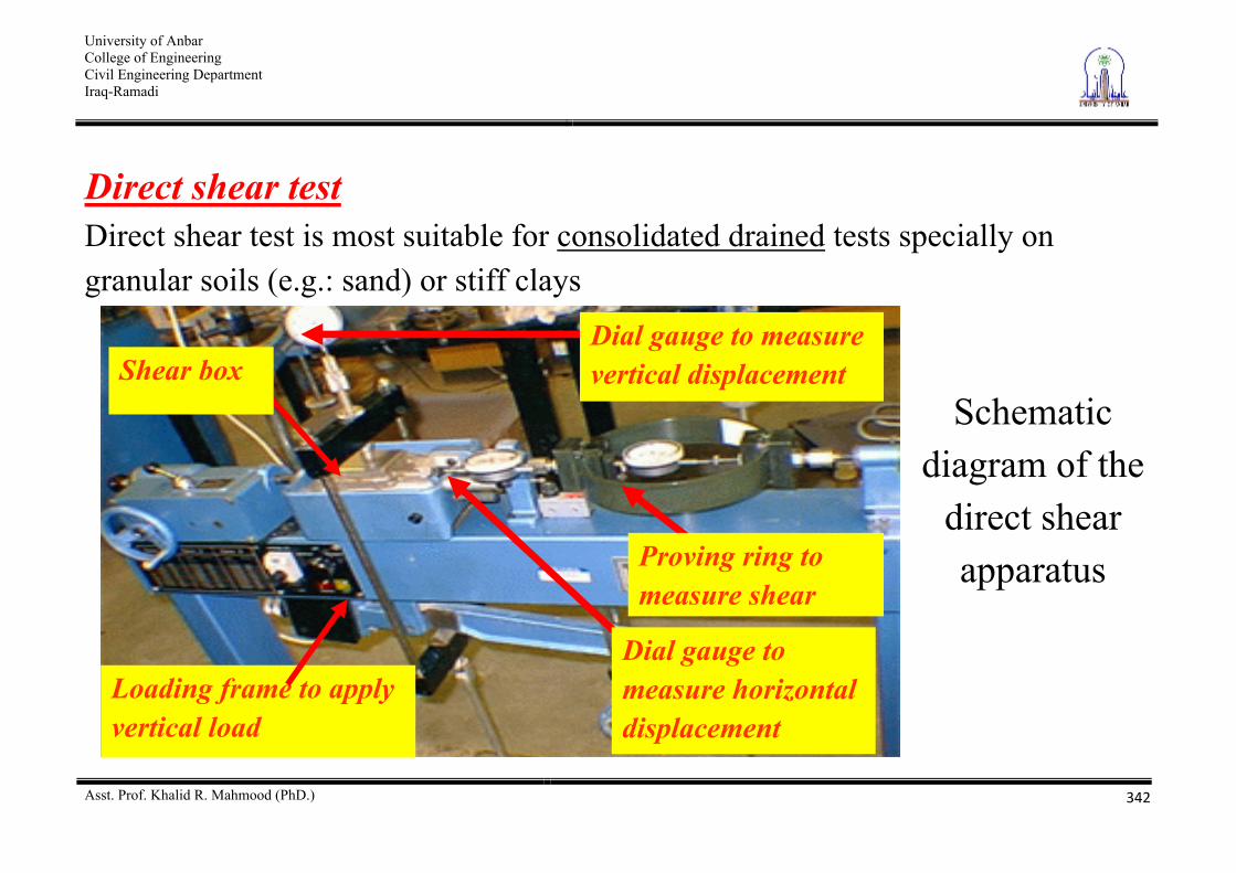
Direct shear test Direct shear test is most suitable for consolidated drained tests specially on granular soils (e.g.: sand) or stiff clays
Loading frame to apply
vertical load
Dial gauge to measure horizontal displacement
Proving ring to measure shear
Dial gauge to measure vertical displacement Shear box
Schematic diagram of the
direct shear apparatus
University of Anbar College of Engineering Civil Engineering Department Iraq-Ramadi
Asst. Prof. Khalid R. Mahmood (PhD.)
343
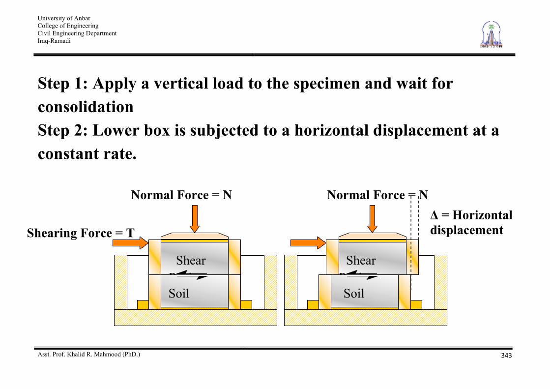
Step 1: Apply a vertical load to the specimen and wait for consolidation Step 2: Lower box is subjected to a horizontal displacement at a constant rate.
Shearing Force = T
Normal Force = N
Soil
Shear Resistan
Normal Force = N
Soil
Shear Resistan
= Horizontal displacement
University of Anbar College of Engineering Civil Engineering Department Iraq-Ramadi
Asst. Prof. Khalid R. Mahmood (PhD.)
344
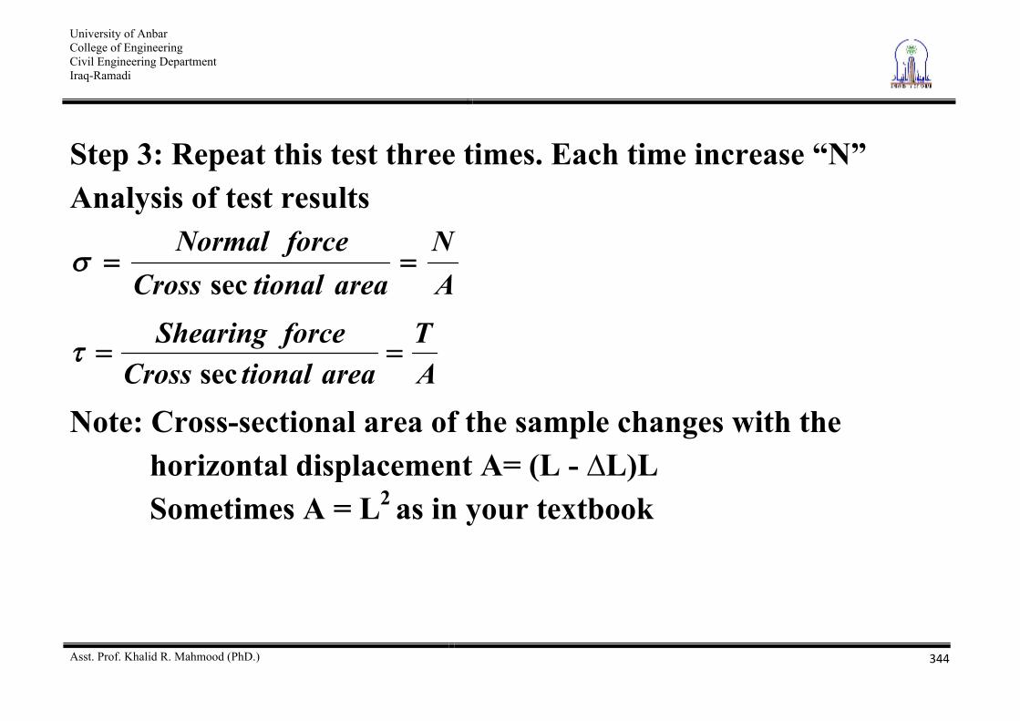
Step 3: Repeat this test three times. Each time increase “N” Analysis of test results
AN
areationalCrossforceNormal
sec
AT
areationalCrossforceShearing
sec
Note: Cross-sectional area of the sample changes with the horizontal displacement A= (L - L)L Sometimes A = L2 as in your textbook
University of Anbar College of Engineering Civil Engineering Department Iraq-Ramadi
Asst. Prof. Khalid R. Mahmood (PhD.)
345
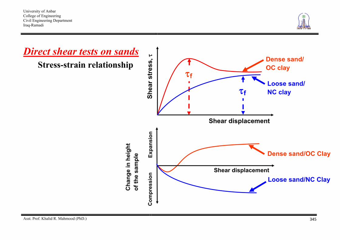
Direct shear tests on sands Stress-strain relationship
Shea
r str
ess,
Shear displacement
Dense sand/ OC clay
f Loose sand/ NC clay f
Dense sand/OC Clay
Cha
nge
in h
eigh
t of
the
sam
ple Ex
pans
ion
Com
pres
sion
Shear displacement Loose sand/NC Clay
University of Anbar College of Engineering Civil Engineering Department Iraq-Ramadi
Asst. Prof. Khalid R. Mahmood (PhD.)
346
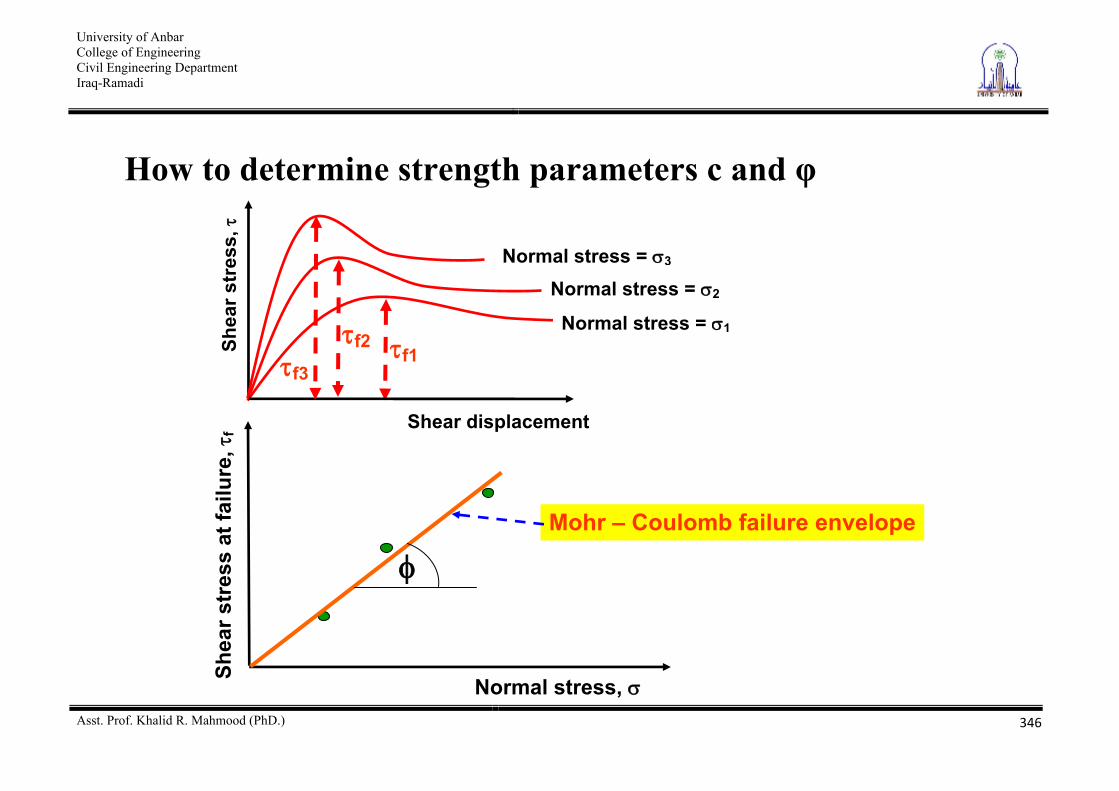
How to determine strength parameters c and
f1
Normal stress = 1
Shea
r str
ess,
Shear displacement
f2
Normal stress = 2
f3
Normal stress = 3
Shea
r str
ess
at fa
ilure
,f
Normal stress,
Mohr – Coulomb failure envelope
University of Anbar College of Engineering Civil Engineering Department Iraq-Ramadi
Asst. Prof. Khalid R. Mahmood (PhD.)
347
Some important facts on strength parameters c and f of sand Sand is cohesionless hence c = 0 Direct shear tests are drained and pore water pressures are dissipated, hence u = 0, Therefore,
= / and c = c/
University of Anbar College of Engineering Civil Engineering Department Iraq-Ramadi
Asst. Prof. Khalid R. Mahmood (PhD.)
348
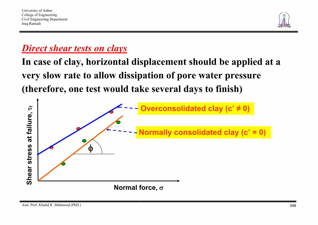
Direct shear tests on clays In case of clay, horizontal displacement should be applied at a very slow rate to allow dissipation of pore water pressure (therefore, one test would take several days to finish)
Shea
r str
ess
at fa
ilure
,f
Normal force,
Normally consolidated clay (c’ = 0)
Overconsolidated clay (c’ 0)
University of Anbar College of Engineering Civil Engineering Department Iraq-Ramadi
Asst. Prof. Khalid R. Mahmood (PhD.)
349
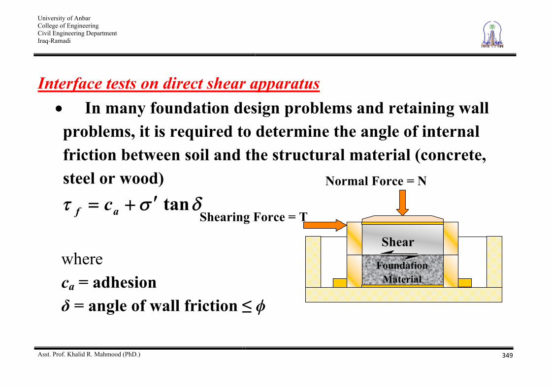
Interface tests on direct shear apparatus In many foundation design problems and retaining wall problems, it is required to determine the angle of internal friction between soil and the structural material (concrete, steel or wood)
tanaf c where ca = adhesion
= angle of wall friction
Shearing Force = T
Normal Force = N
Foundation Material
Shear Resistance
University of Anbar College of Engineering Civil Engineering Department Iraq-Ramadi
Asst. Prof. Khalid R. Mahmood (PhD.)
350
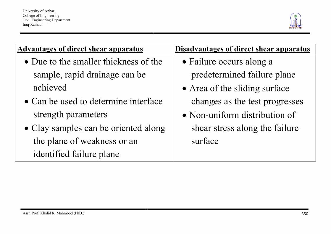
Advantages of direct shear apparatus Disadvantages of direct shear apparatus
Due to the smaller thickness of the sample, rapid drainage can be achieved
Can be used to determine interface strength parameters
Clay samples can be oriented along the plane of weakness or an identified failure plane
Failure occurs along a predetermined failure plane
Area of the sliding surface changes as the test progresses
Non-uniform distribution of shear stress along the failure surface
University of Anbar College of Engineering Civil Engineering Department Iraq-Ramadi
Asst. Prof. Khalid R. Mahmood (PhD.)
351
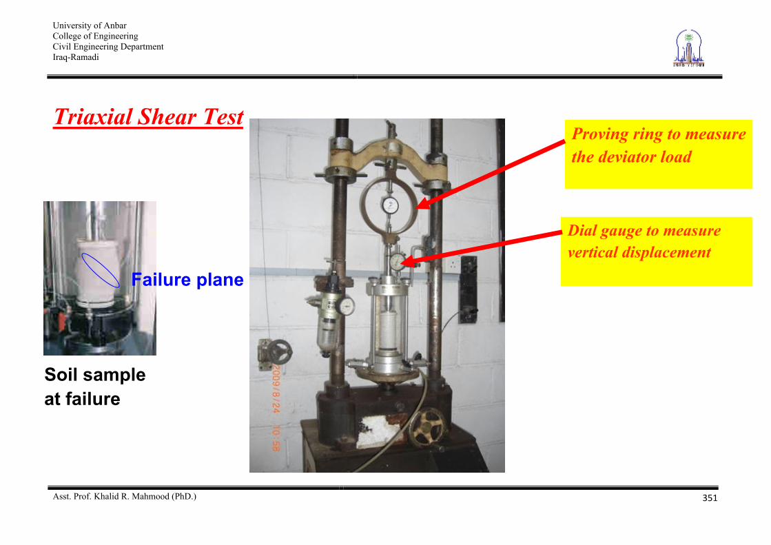
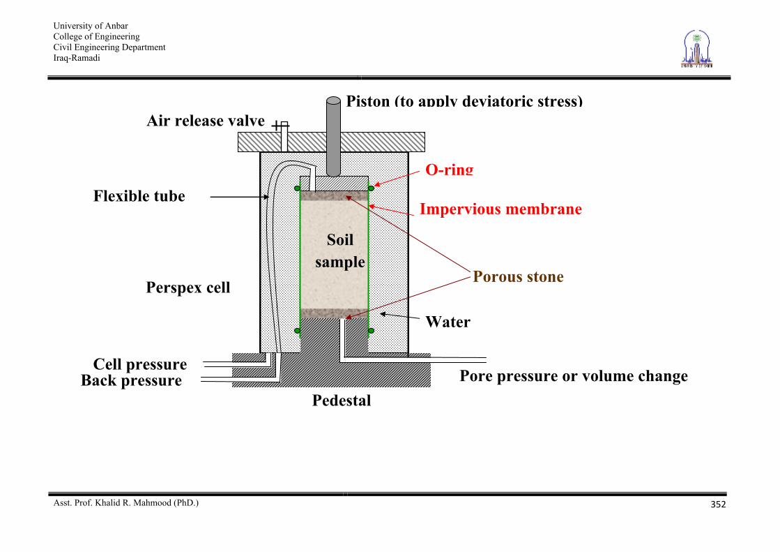
Triaxial Shear Test
Soil sample at failure
Failure plane
Proving ring to measure the deviator load
Dial gauge to measure vertical displacement
University of Anbar College of Engineering Civil Engineering Department Iraq-Ramadi
Asst. Prof. Khalid R. Mahmood (PhD.)
352
Porous stone
Impervious membrane
Piston (to apply deviatoric stress)
O-ring
Pedestal
Perspex cell
Cell pressure Back pressure Pore pressure or volume change
Water
Soil sample
Air release valve
Flexible tube
University of Anbar College of Engineering Civil Engineering Department Iraq-Ramadi
Asst. Prof. Khalid R. Mahmood (PhD.)
353
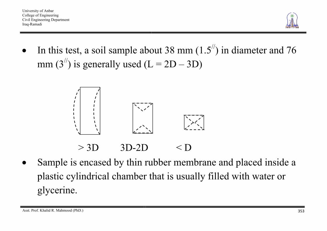
In this test, a soil sample about 38 mm (1.5//) in diameter and 76 mm (3//) is generally used (L = 2D – 3D)
> 3D 3D-2D < D Sample is encased by thin rubber membrane and placed inside a
plastic cylindrical chamber that is usually filled with water or glycerine.
University of Anbar College of Engineering Civil Engineering Department Iraq-Ramadi
Asst. Prof. Khalid R. Mahmood (PhD.)
354
Confining pressure is applied by compression of fluid in the chamber (air sometimes used as a compression medium)
To cause shear failure in the sample, axial stress is applied through a vertical loading ram (called deviator stress). This can be done in one of two ways
Stress-controlled – load is applied in increments and the deformation is measured
Strain-controlled – load is applied at a constant rate of deformation
University of Anbar College of Engineering Civil Engineering Department Iraq-Ramadi
Asst. Prof. Khalid R. Mahmood (PhD.)
355
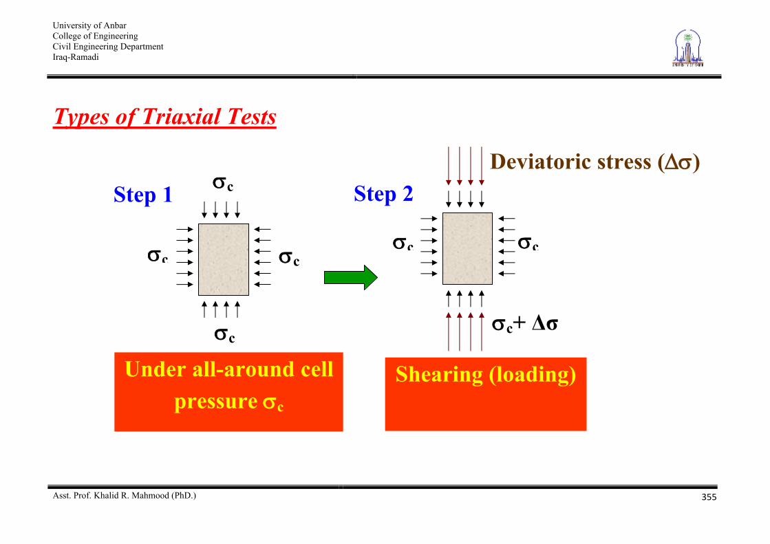
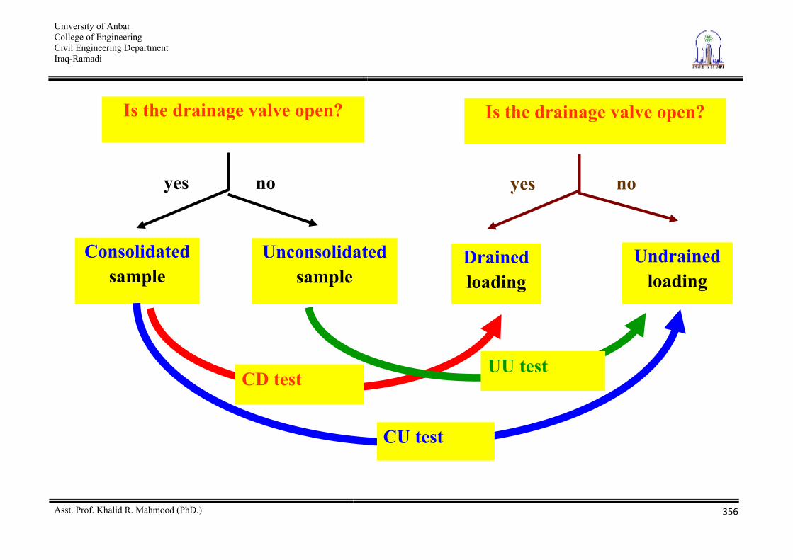
Types of Triaxial Tests
Under all-around cell pressure c
c c
c
c Step 1 Deviatoric stress ( )
Shearing (loading)
Step 2
c c
c+
University of Anbar College of Engineering Civil Engineering Department Iraq-Ramadi
Asst. Prof. Khalid R. Mahmood (PhD.)
356
Is the drainage valve open?
yes no
Consolidated sample
Unconsolidated sample
Is the drainage valve open?
yes no
Drained loading
Undrained loading
CD test
CU test
UU test
University of Anbar College of Engineering Civil Engineering Department Iraq-Ramadi
Asst. Prof. Khalid R. Mahmood (PhD.)
357
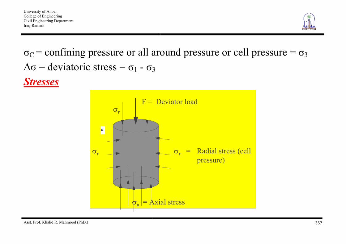
C = confining pressure or all around pressure or cell pressure = 3 = deviatoric stress = 1 - 3
Stresses
r r = Radial stress (cellpressure)
a = Axial stress
F = Deviator loadr
u
University of Anbar College of Engineering Civil Engineering Department Iraq-Ramadi
Asst. Prof. Khalid R. Mahmood (PhD.)
358
From vertical equilibrium we have a rFA
The term F/A is known as the deviator stress, and is usually given the symbol .
Hence we can write = a - r = 1 - 3 (The axial and radial stresses are principal stresses)
If = 0 increasing cell pressure will result in:
Volumetric compression if the soil is free to drain. The effective stresses will increase and so will the strength
University of Anbar College of Engineering Civil Engineering Department Iraq-Ramadi
Asst. Prof. Khalid R. Mahmood (PhD.)
359
Increasing pore water pressure if soil volume is constant (that is, undrained). As the effective stresses cannot change it follows that
u = 3 Strains From the measurements of change in height, dh, and change in volume dV we can determine
Axial strain a = -dh/h0
Volume strain v = -dV/V0
Where h0 is the initial height, and V0 the initial volume. The conventional small strain assumption is generally used.
University of Anbar College of Engineering Civil Engineering Department Iraq-Ramadi
Asst. Prof. Khalid R. Mahmood (PhD.)
360
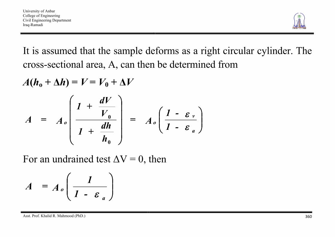
It is assumed that the sample deforms as a right circular cylinder. The cross-sectional area, A, can then be determined from
A(ho + h) = V = V0 + V
a
voo -1
-1 A=
hdh + 1
VdV + 1
A= A
0
0
For an undrained test V = 0, then
ao -1
1 A= A
University of Anbar College of Engineering Civil Engineering Department Iraq-Ramadi
Asst. Prof. Khalid R. Mahmood (PhD.)
361
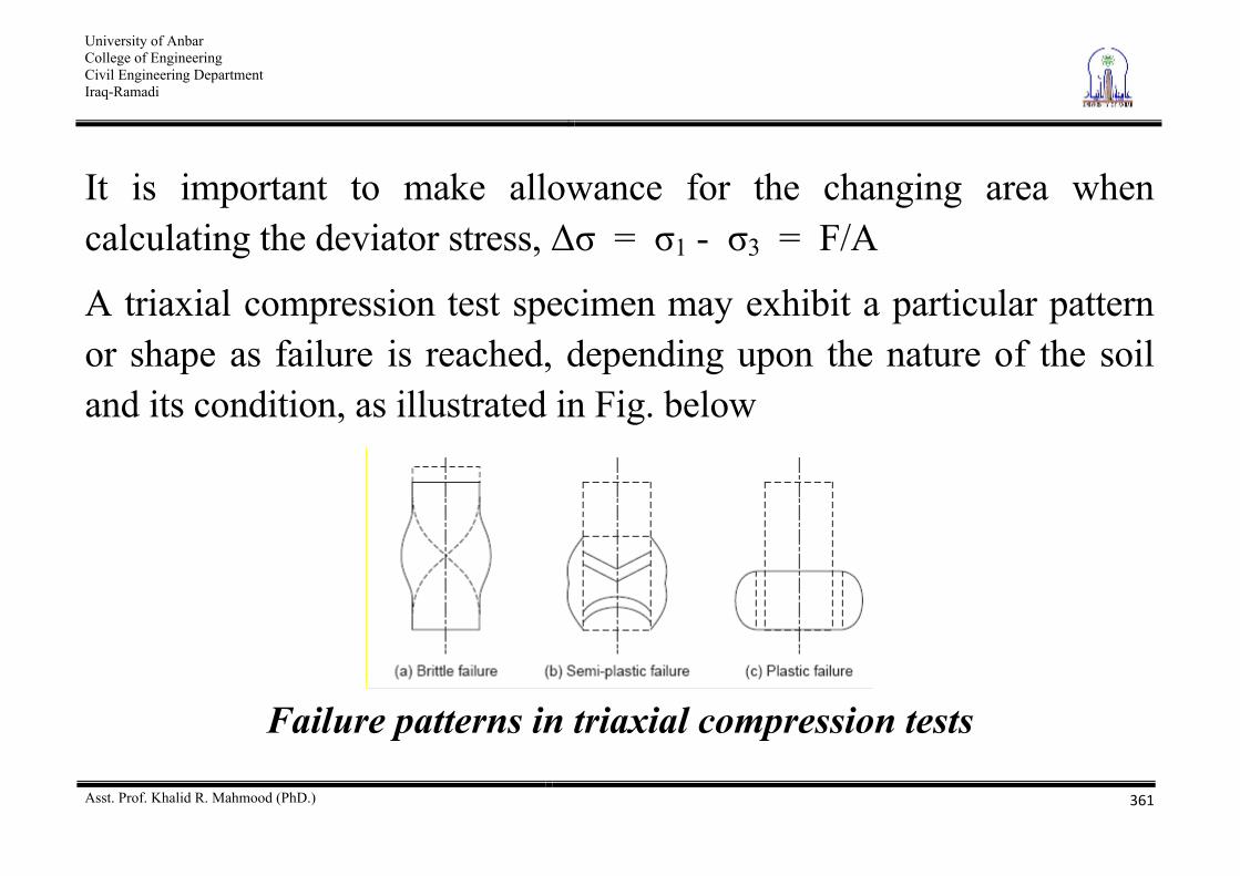
It is important to make allowance for the changing area when calculating the deviator stress, = 1 - 3 = F/A
A triaxial compression test specimen may exhibit a particular pattern or shape as failure is reached, depending upon the nature of the soil and its condition, as illustrated in Fig. below
Failure patterns in triaxial compression tests
University of Anbar College of Engineering Civil Engineering Department Iraq-Ramadi
Asst. Prof. Khalid R. Mahmood (PhD.)
362
brittle failure with well-defined shear plane, semi-plastic failure showing shear cones and some lateral bulging, Plastic failure with well-expressed lateral bulging.
In the case of plastic failure, the strain goes on increasing slowly at a reduced rate with increasing stress, with no specific stage to pin-point failure. In such a case, failure is assumed to have taken place when the strain reaches an arbitrary value such as 20%.
University of Anbar College of Engineering Civil Engineering Department Iraq-Ramadi
Asst. Prof. Khalid R. Mahmood (PhD.)
363
Merits of Triaxial Compression Test The following are the significant points of merit of triaxial compression test: (1) Failure occurs along the weakest plane unlike along the
predetermined plane in the case of direct shear test. (2) The stress distribution on the failure plane is much more uniform
than it is in the direct shear test: the failure is not also progressive, but the shear strength is mobilised all at once. Of course, the effect of end restraint for the sample is considered to be a disadvantage; however, this may not have pronounced effect on the results since
University of Anbar College of Engineering Civil Engineering Department Iraq-Ramadi
Asst. Prof. Khalid R. Mahmood (PhD.)
364
the conditions are more uniform to the desired degree near the middle of the height of the sample where failure usually occurs.
(3) Complete control of the drainage conditions is possible with the triaxial compression test; this would enable one to simulate the field conditions better.
(4) The possibility to vary the cell pressure or confining pressure also affords another means to simulate the field conditions for the sample, so that the results are more meaningfully interpreted.
(5) Precise measurements of pore water pressure and volume changes during the test are possible.
University of Anbar College of Engineering Civil Engineering Department Iraq-Ramadi
Asst. Prof. Khalid R. Mahmood (PhD.)
365
(6) The state of stress within the specimen is known on all planes and not only on a predetermined failure plane as it is with direct shear tests.
(7) The state of stress on any plane is capable of being determined not only at failure but also at any earlier stage.
(8) Special tests such as extension tests are also possible to be conducted with the triaxial testing apparatus.
(9) It provides an ingenious and a symmetrical three-dimensional stress system better suited to simulate field conditions.
University of Anbar College of Engineering Civil Engineering Department Iraq-Ramadi
Asst. Prof. Khalid R. Mahmood (PhD.)
366
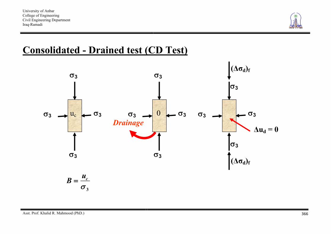
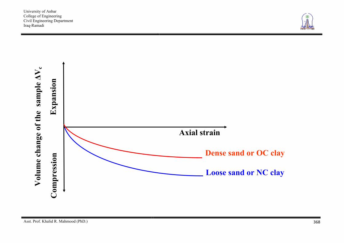
Consolidated - Drained test (CD Test)
3
cuB
Drainage 3 3
3
3
uc 3 3
3
3
0 3 3
3
3
ud = 0
( d)f
( d)f
University of Anbar College of Engineering Civil Engineering Department Iraq-Ramadi
Asst. Prof. Khalid R. Mahmood (PhD.)
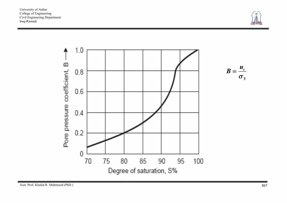
367
3
cuB
University of Anbar College of Engineering Civil Engineering Department Iraq-Ramadi
Asst. Prof. Khalid R. Mahmood (PhD.)
368
Dense sand or OC clay
Loose sand or NC clay
Vol
ume
chan
ge o
f the
sam
ple
Vc
Com
pres
sion
Axial strain
Exp
ansi
on
University of Anbar College of Engineering Civil Engineering Department Iraq-Ramadi
Asst. Prof. Khalid R. Mahmood (PhD.)
369
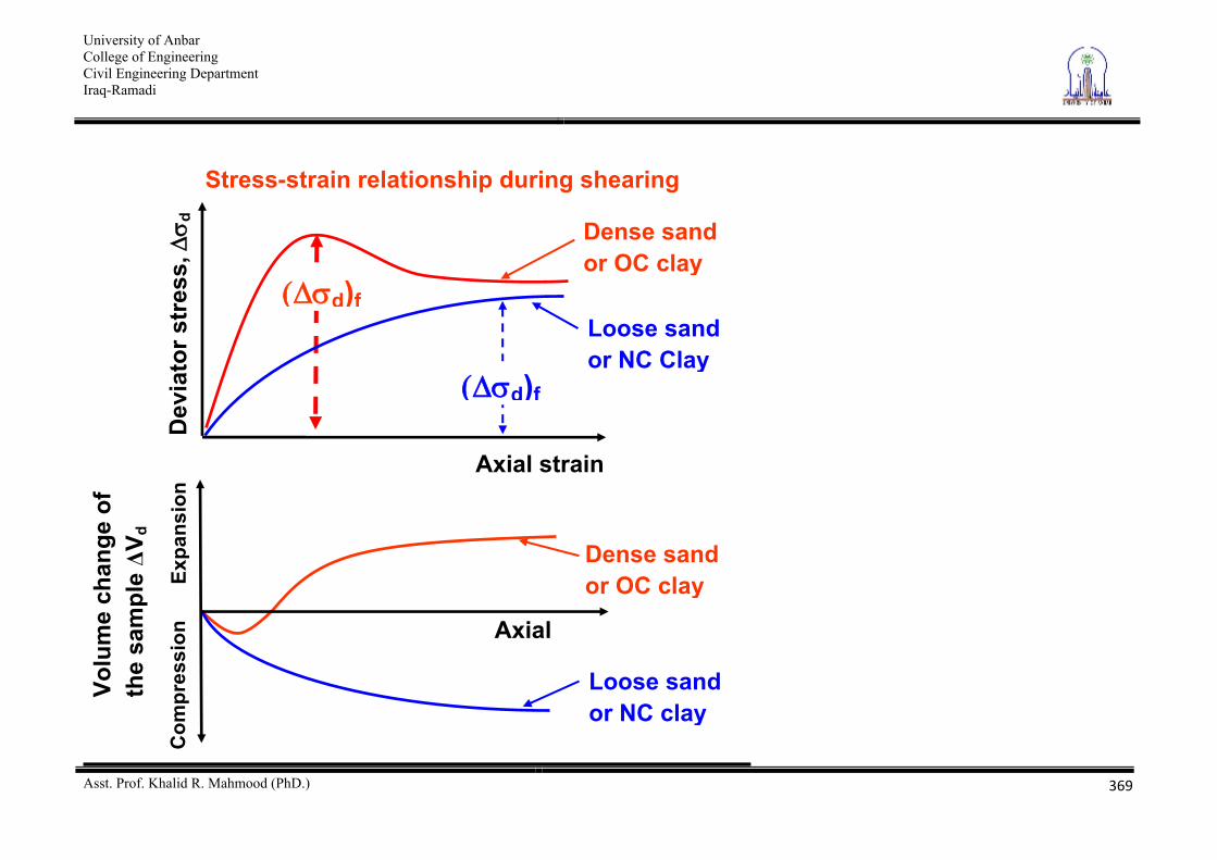
Dev
iato
r str
ess,
d
Axial strain
Dense sand or OC clay
d)f
Expa
nsio
n
Dense sand or OC clay
Loose sand or NC clay
Volu
me
chan
ge o
f th
e sa
mpl
e V d
Com
pres
sion
Axial
Stress-strain relationship during shearing
Loose sand or NC Clay
d)f
University of Anbar College of Engineering Civil Engineering Department Iraq-Ramadi
Asst. Prof. Khalid R. Mahmood (PhD.)
370
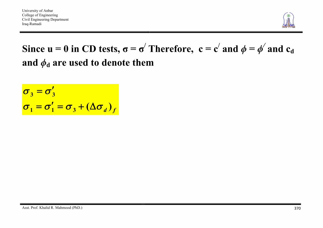
Since u = 0 in CD tests, = / Therefore, c = c/ and = / and cd and d are used to denote them
fd )(311
33
University of Anbar College of Engineering Civil Engineering Department Iraq-Ramadi
Asst. Prof. Khalid R. Mahmood (PhD.)
371
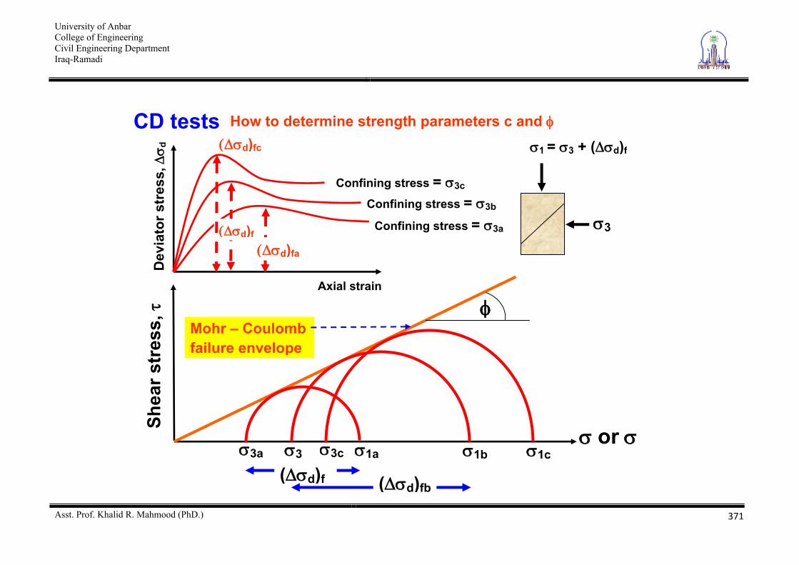
CD tests How to determine strength parameters c and
Dev
iato
r str
ess,
d
Axial strain
Shea
r str
ess,
or
Mohr – Coulomb failure envelope
d)fa
Confining stress = 3a d)f
Confining stress = 3b
d)fc
Confining stress = 3c
3c 1c 3a 1a
( d)f
3 1b
( d)fb
1 = 3 + ( d)f
3
University of Anbar College of Engineering Civil Engineering Department Iraq-Ramadi
Asst. Prof. Khalid R. Mahmood (PhD.)
372
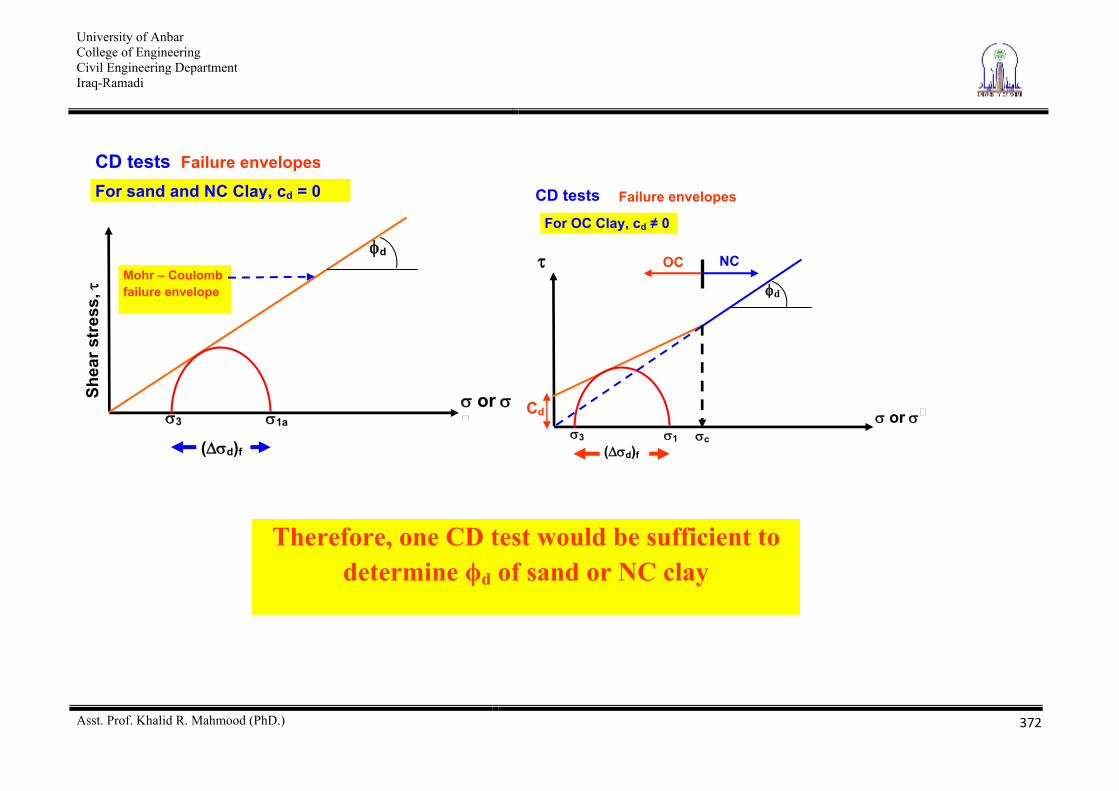
CD tests Failure envelopes
Shea
r str
ess,
or
d
Mohr – Coulomb failure envelope
3 1a
( d)f
For sand and NC Clay, cd = 0 CD tests For OC Clay, cd 0
or
d
3 1 ( d)f
c
OC NC
Failure envelopes
Cd
Therefore, one CD test would be sufficient to determine d of sand or NC clay
University of Anbar College of Engineering Civil Engineering Department Iraq-Ramadi
Asst. Prof. Khalid R. Mahmood (PhD.)
373
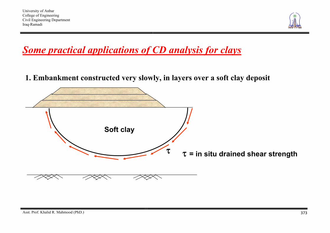
Some practical applications of CD analysis for clays
= in situ drained shear strength
Soft clay
1. Embankment constructed very slowly, in layers over a soft clay deposit
University of Anbar College of Engineering Civil Engineering Department Iraq-Ramadi
Asst. Prof. Khalid R. Mahmood (PhD.)
374
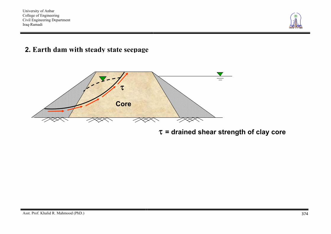
2. Earth dam with steady state seepage
= drained shear strength of clay core
Core
University of Anbar College of Engineering Civil Engineering Department Iraq-Ramadi
Asst. Prof. Khalid R. Mahmood (PhD.)
375
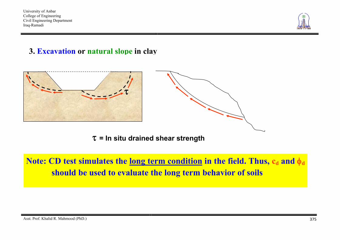
3. Excavation or natural slope in clay
= In situ drained shear strength
Note: CD test simulates the long term condition in the field. Thus, cd and d should be used to evaluate the long term behavior of soils
University of Anbar College of Engineering Civil Engineering Department Iraq-Ramadi
Asst. Prof. Khalid R. Mahmood (PhD.)
376
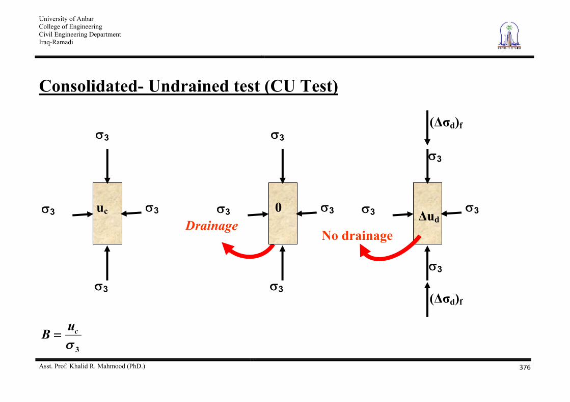
Consolidated- Undrained test (CU Test)
3
cuB
Drainage 3 3
3
3
uc 3 3
3
3
0 3 3
3
3
ud
( d)f
( d)f
No drainage
University of Anbar College of Engineering Civil Engineering Department Iraq-Ramadi
Asst. Prof. Khalid R. Mahmood (PhD.)
377
University of Anbar College of Engineering Civil Engineering Department Iraq-Ramadi
Asst. Prof. Khalid R. Mahmood (PhD.)
378
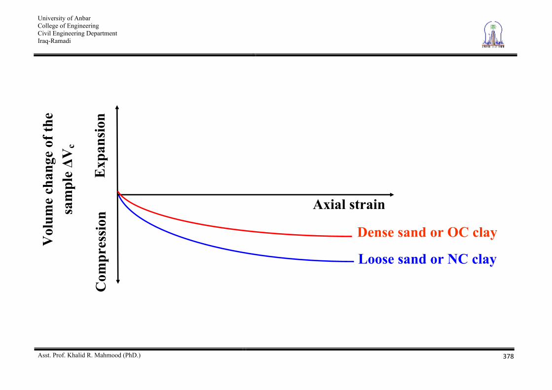
Dense sand or OC clay
Loose sand or NC clay
Vol
ume
chan
ge o
f the
sa
mpl
e V
c
Com
pres
sion
Axial strain
Exp
ansi
on
University of Anbar College of Engineering Civil Engineering Department Iraq-Ramadi
Asst. Prof. Khalid R. Mahmood (PhD.)
379
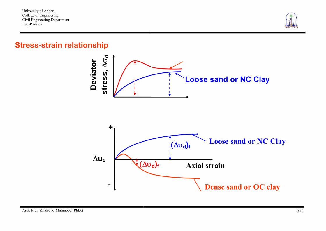
Stress-strain relationship
Dev
iato
r st
ress
,d
Loose sand or NC Clay
d)f
d)f
Dense sand or OC clay
ud
+
-
Axial strain
Loose sand or NC Clay
University of Anbar College of Engineering Civil Engineering Department Iraq-Ramadi
Asst. Prof. Khalid R. Mahmood (PhD.)
380
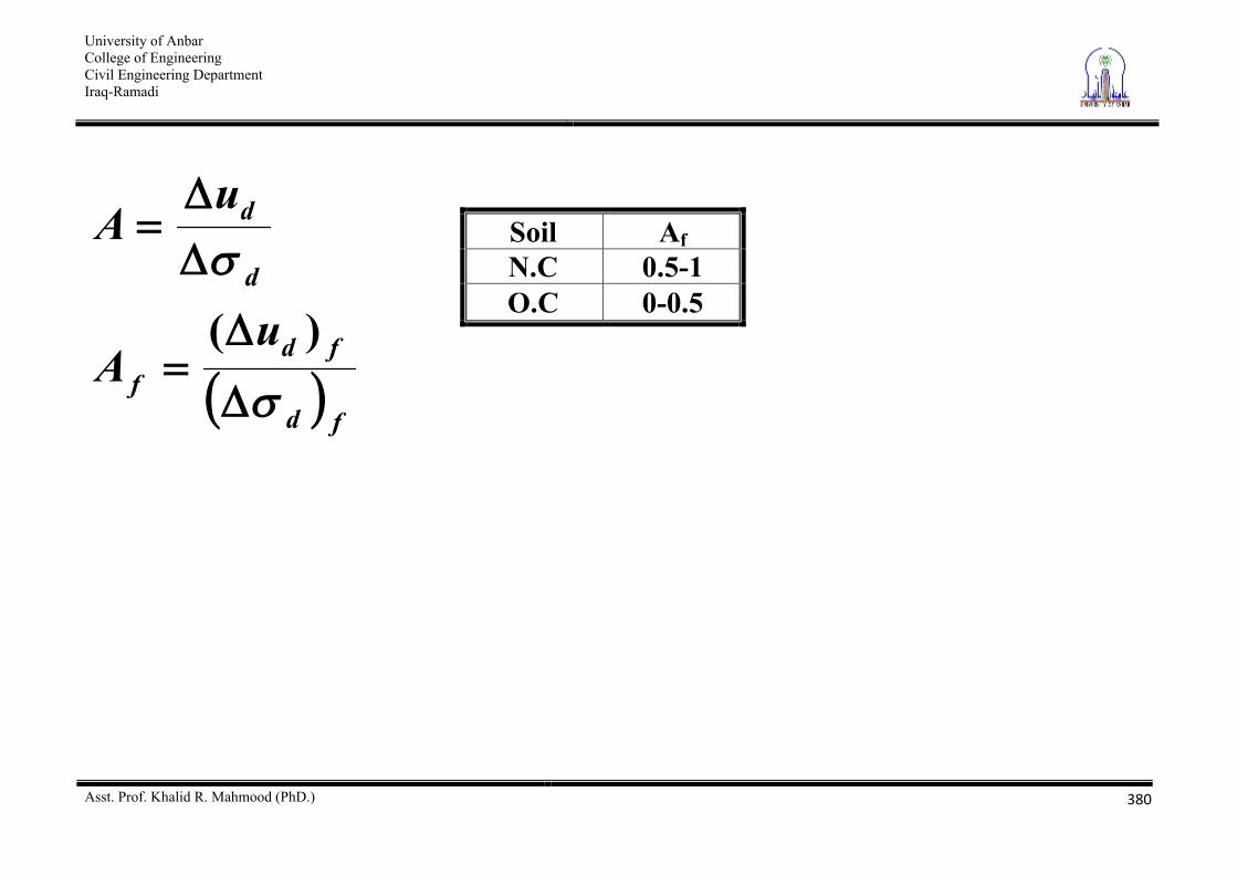
fd
fdf
d
d
uA
uA
)(
Soil Af N.C 0.5-1 O.C 0-0.5
University of Anbar College of Engineering Civil Engineering Department Iraq-Ramadi
Asst. Prof. Khalid R. Mahmood (PhD.)
381
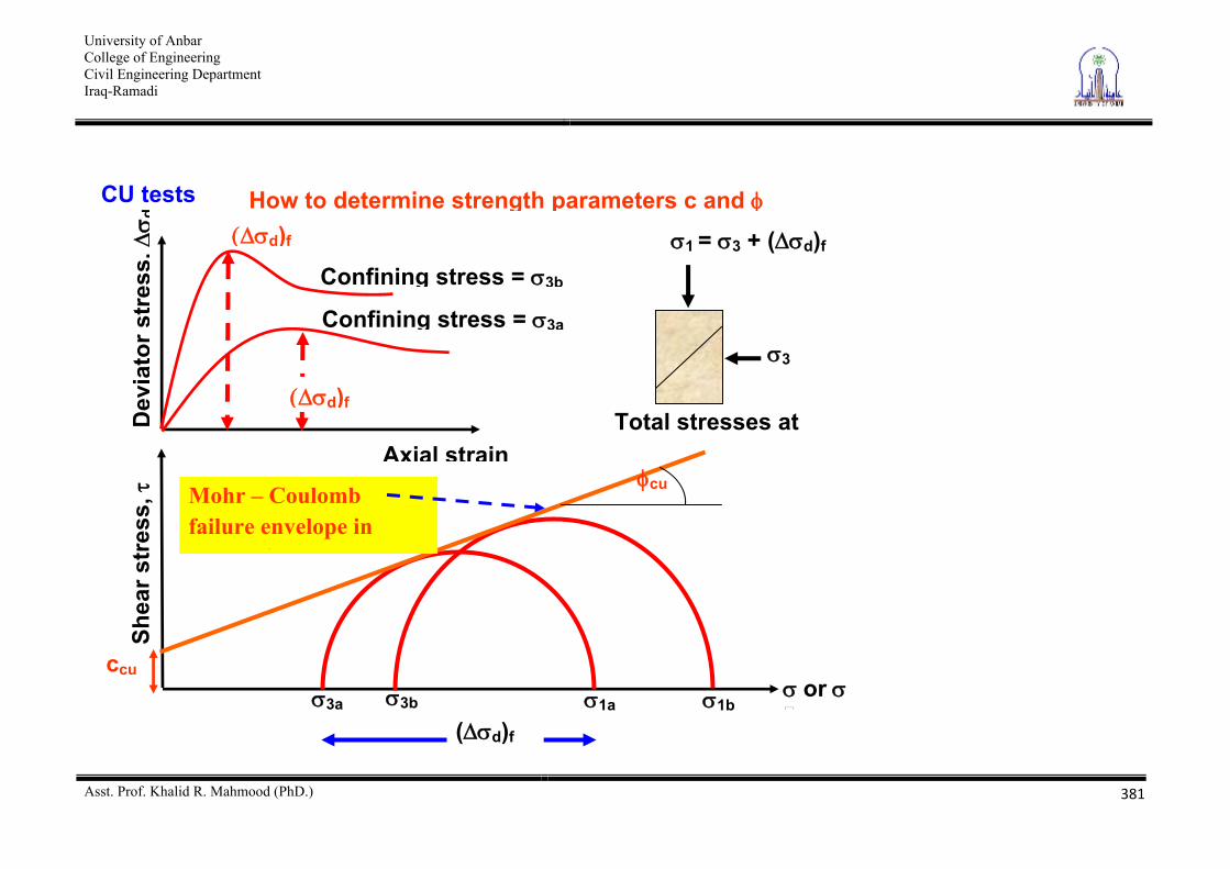
CU tests How to determine strength parameters c and
Dev
iato
r str
ess,
d
Axial strain
Shea
r str
ess,
or
d)f
Confining stress = 3b
3b 1b 3a 1a
( d)f
cu Mohr – Coulomb failure envelope in terms of total stresses
ccu
1 = 3 + ( d)f
3
Total stresses at d)f
Confining stress = 3a
University of Anbar College of Engineering Civil Engineering Department Iraq-Ramadi
Asst. Prof. Khalid R. Mahmood (PhD.)
382
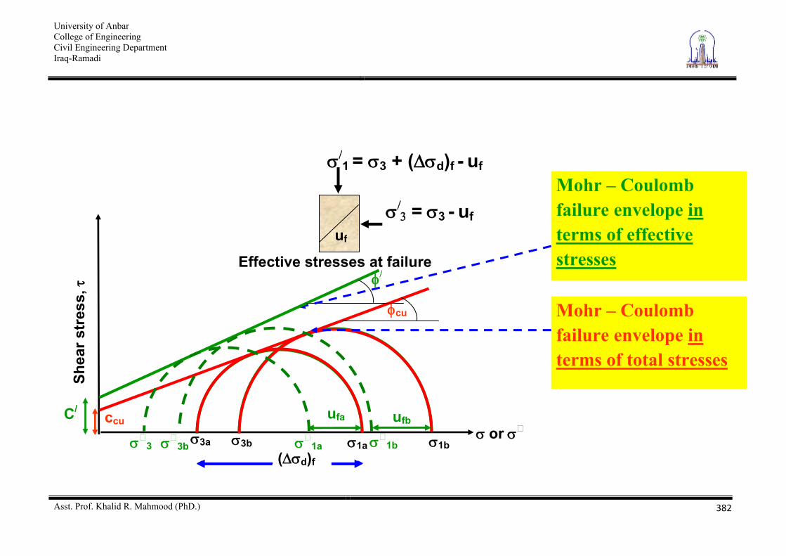
( d)fa
Shea
r str
ess,
or3b 1b 3a 1a
( d)f
cu Mohr – Coulomb failure envelope in terms of total stresses
ccu
1b 3 1a
Mohr – Coulomb failure envelope in terms of effective stresses
C/ ufa ufb
1 = 3 + ( d)f - uf
= 3 - uf
Effective stresses at failure
uf
3b
University of Anbar College of Engineering Civil Engineering Department Iraq-Ramadi
Asst. Prof. Khalid R. Mahmood (PhD.)
383
Shear strength parameters in terms of total stresses are Ccu and cu Shear strength parameters in terms of effective stresses are C/ and / C/= Cdrained and / = drained
University of Anbar College of Engineering Civil Engineering Department Iraq-Ramadi
Asst. Prof. Khalid R. Mahmood (PhD.)
384
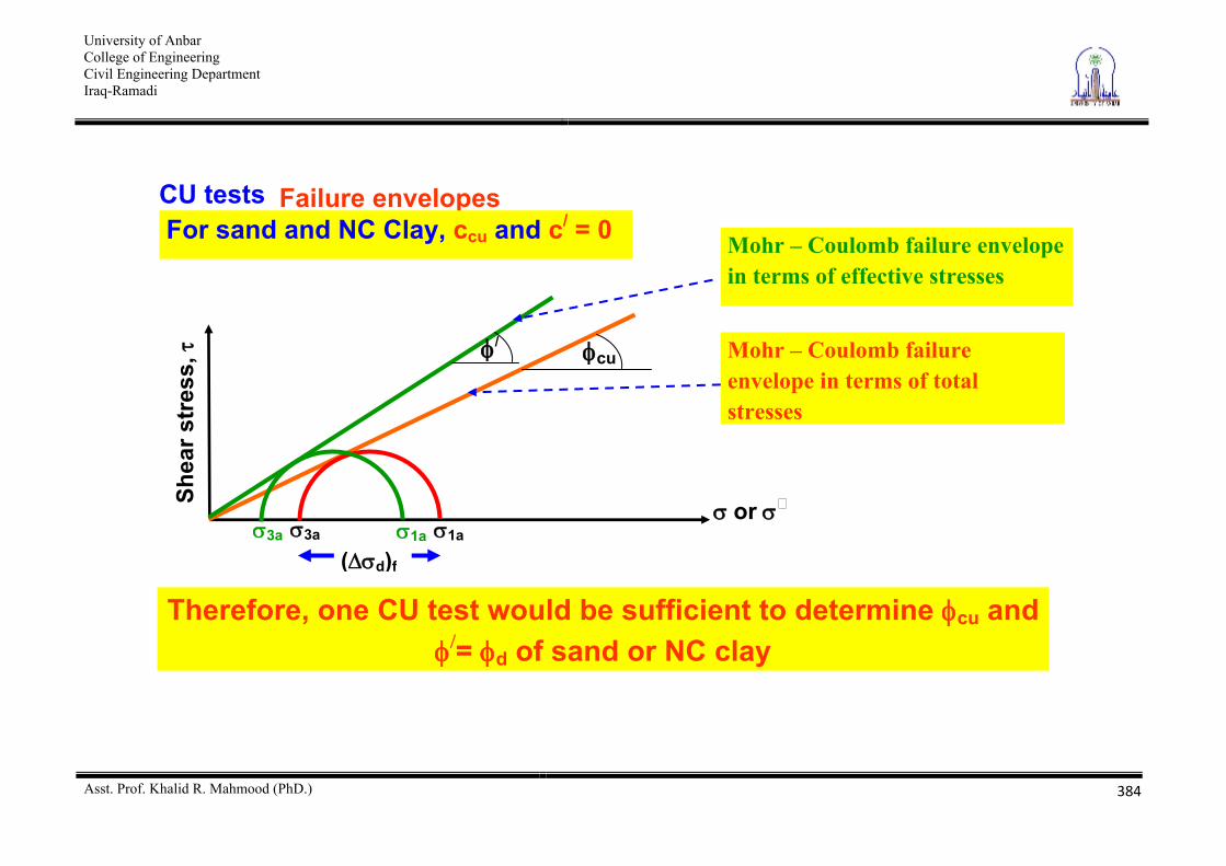
CU tests Failure envelopesFor sand and NC Clay, ccu and c/ = 0
Therefore, one CU test would be sufficient to determine cu and = d of sand or NC clay
Shea
r str
ess,
or
cu Mohr – Coulomb failure envelope in terms of total stresses
3a 1a
( d)f
3a 1a
/
Mohr – Coulomb failure envelope in terms of effective stresses
University of Anbar College of Engineering Civil Engineering Department Iraq-Ramadi
Asst. Prof. Khalid R. Mahmood (PhD.)
385
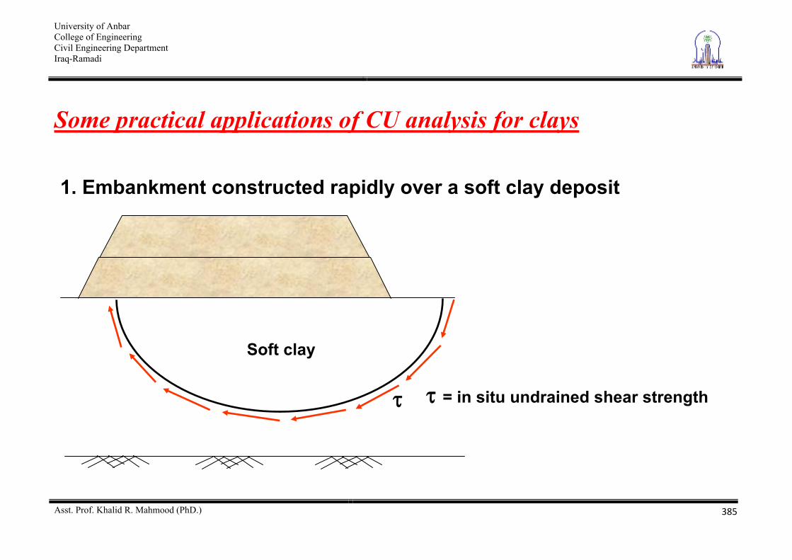
Some practical applications of CU analysis for clays
= in situ undrained shear strength
Soft clay
1. Embankment constructed rapidly over a soft clay deposit
University of Anbar College of Engineering Civil Engineering Department Iraq-Ramadi
Asst. Prof. Khalid R. Mahmood (PhD.)
386
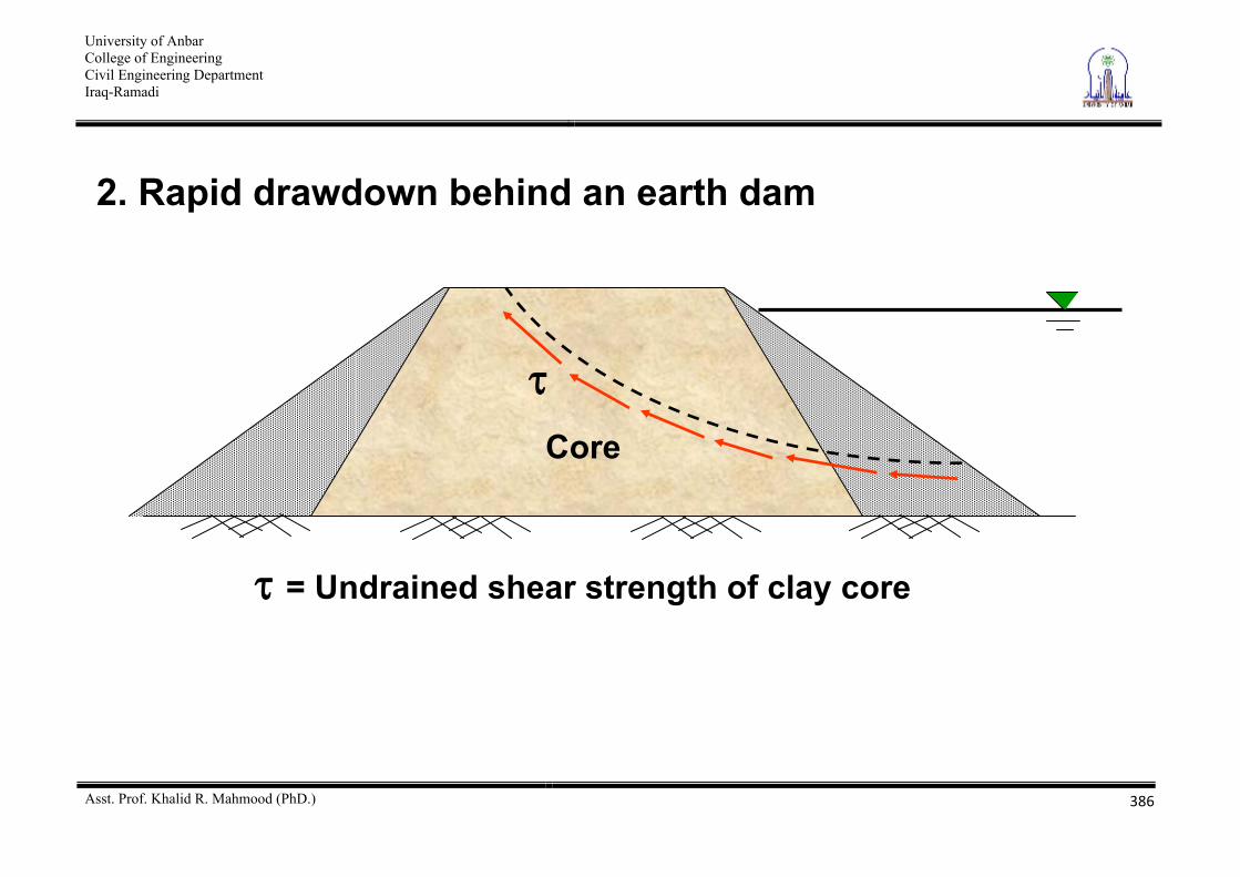
2. Rapid drawdown behind an earth dam
= Undrained shear strength of clay core
Core
University of Anbar College of Engineering Civil Engineering Department Iraq-Ramadi
Asst. Prof. Khalid R. Mahmood (PhD.)
387
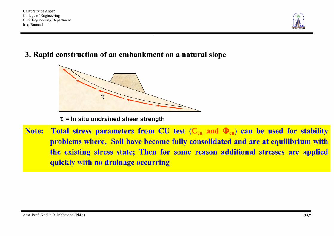
3. Rapid construction of an embankment on a natural slope
Note: Total stress parameters from CU test (Ccu and cu) can be used for stability problems where, Soil have become fully consolidated and are at equilibrium with the existing stress state; Then for some reason additional stresses are applied quickly with no drainage occurring
= In situ undrained shear strength
University of Anbar College of Engineering Civil Engineering Department Iraq-Ramadi
Asst. Prof. Khalid R. Mahmood (PhD.)
388
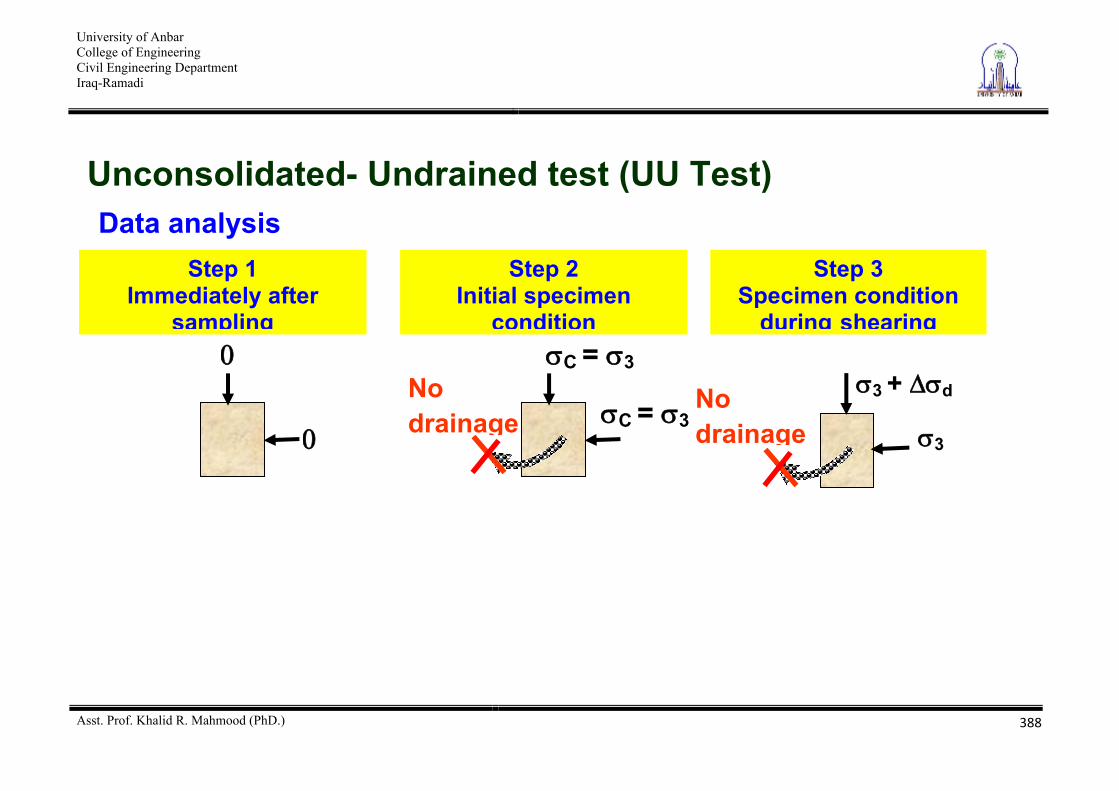
Unconsolidated- Undrained test (UU Test) Data analysis
C = 3
C = 3 No drainage
Step 2 Initial specimen
condition
3 + d
3
No drainage
Step 3 Specimen condition
during shearing
Step 1 Immediately after
sampling
University of Anbar College of Engineering Civil Engineering Department Iraq-Ramadi
Asst. Prof. Khalid R. Mahmood (PhD.)
389
= +
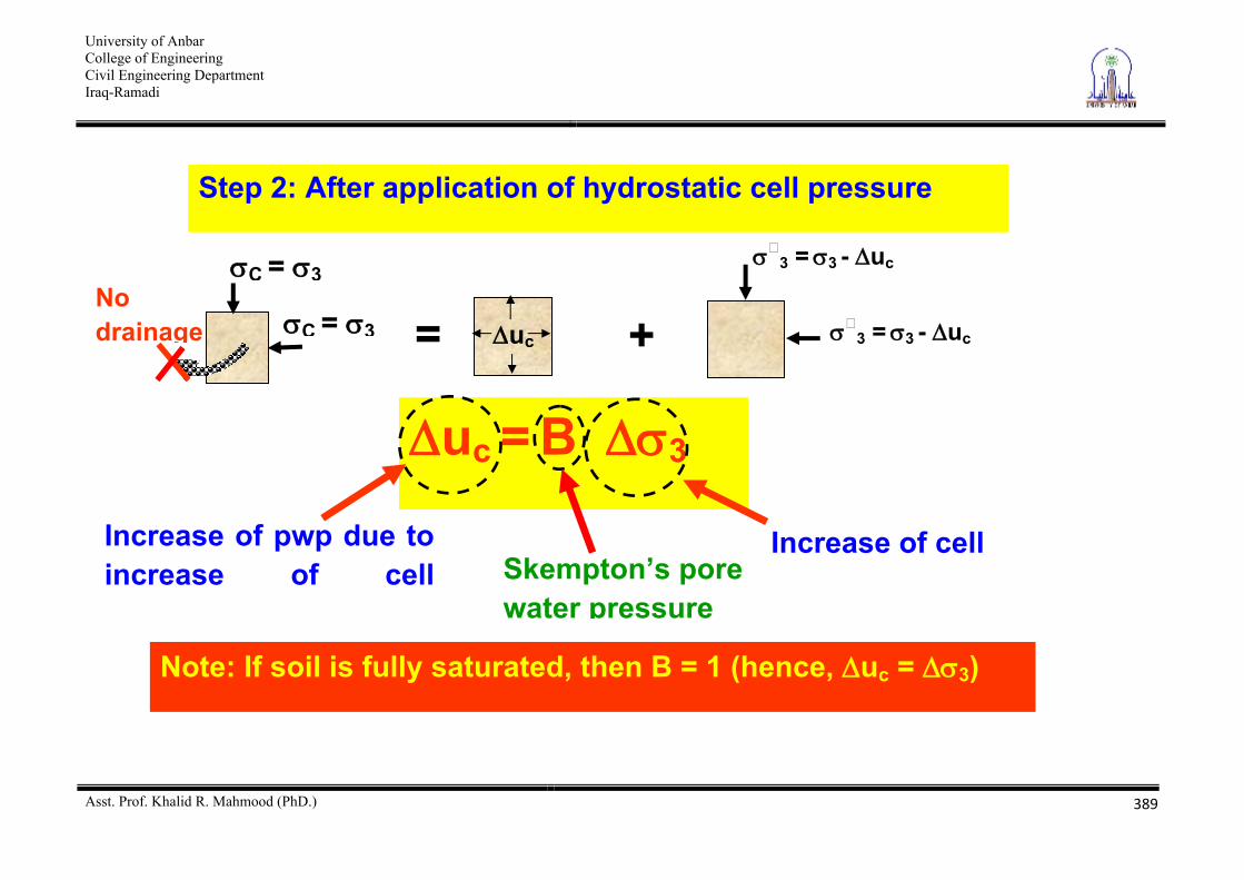
Step 2: After application of hydrostatic cell pressure
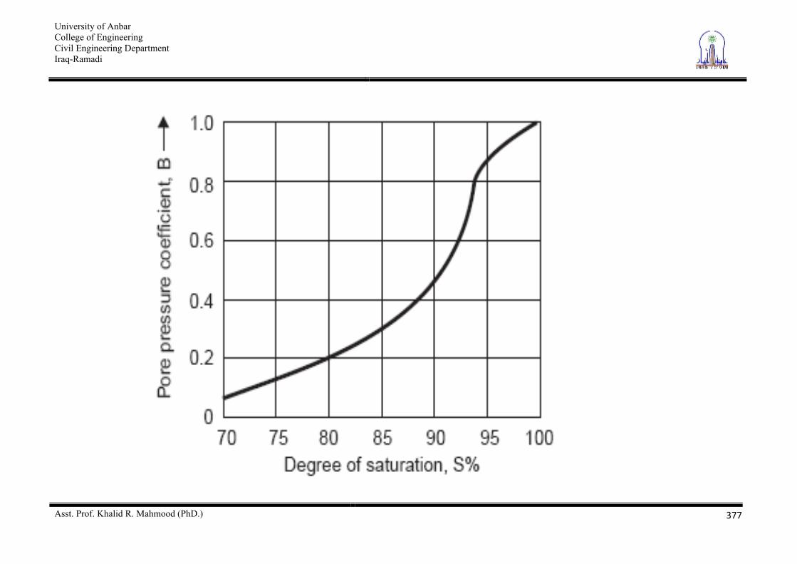
uc = B 3
C = 3
C = 3 uc
3 = 3 - uc
3 = 3 - uc
No drainage
Increase of pwp due to increase of cell
Increase of cell Skempton’s pore water pressure
Note: If soil is fully saturated, then B = 1 (hence, uc = 3)
University of Anbar College of Engineering Civil Engineering Department Iraq-Ramadi
Asst. Prof. Khalid R. Mahmood (PhD.)
390
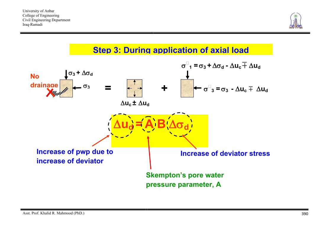
Step 3: During application of axial load
3 + d
3
No drainage
1 = 3 + d - uc ud
3 = 3 - uc ud
ud = A B d
uc ± ud
= +
Increase of pwp due to increase of deviator
Increase of deviator stress
Skempton’s pore water pressure parameter, A
University of Anbar College of Engineering Civil Engineering Department Iraq-Ramadi
Asst. Prof. Khalid R. Mahmood (PhD.)
391
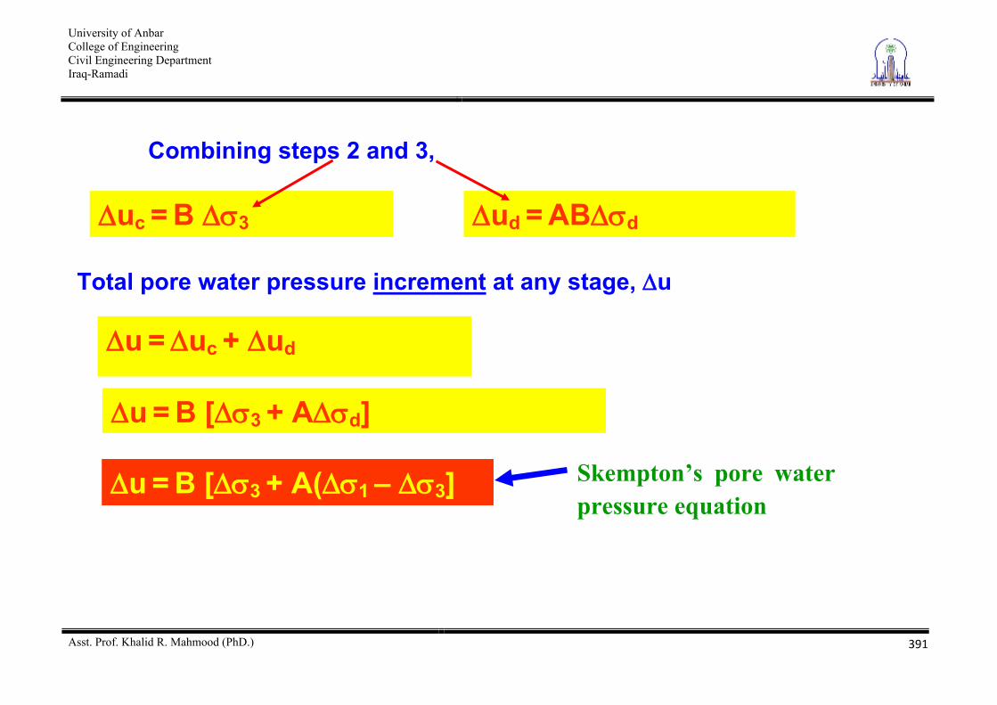
Combining steps 2 and 3,
uc = B 3 ud = AB d
u = uc + ud
Total pore water pressure increment at any stage, u
u = B [ 3 + A d]
Skempton’s pore water pressure equation
u = B [ 3 + A( 1 – 3]
University of Anbar College of Engineering Civil Engineering Department Iraq-Ramadi
Asst. Prof. Khalid R. Mahmood (PhD.)
392
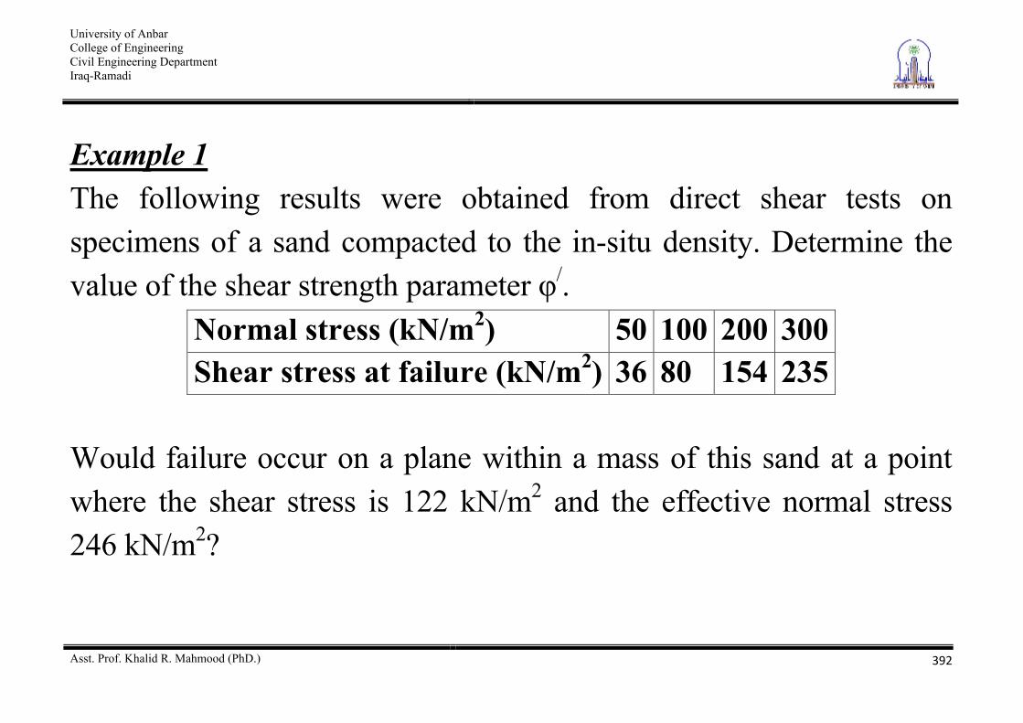
Example 1 The following results were obtained from direct shear tests on specimens of a sand compacted to the in-situ density. Determine the value of the shear strength parameter /.
Normal stress (kN/m2) 50 100 200 300 Shear stress at failure (kN/m2) 36 80 154 235
Would failure occur on a plane within a mass of this sand at a point where the shear stress is 122 kN/m2 and the effective normal stress 246 kN/m2?
University of Anbar College of Engineering Civil Engineering Department Iraq-Ramadi
Asst. Prof. Khalid R. Mahmood (PhD.)
393
University of Anbar College of Engineering Civil Engineering Department Iraq-Ramadi
Asst. Prof. Khalid R. Mahmood (PhD.)
394
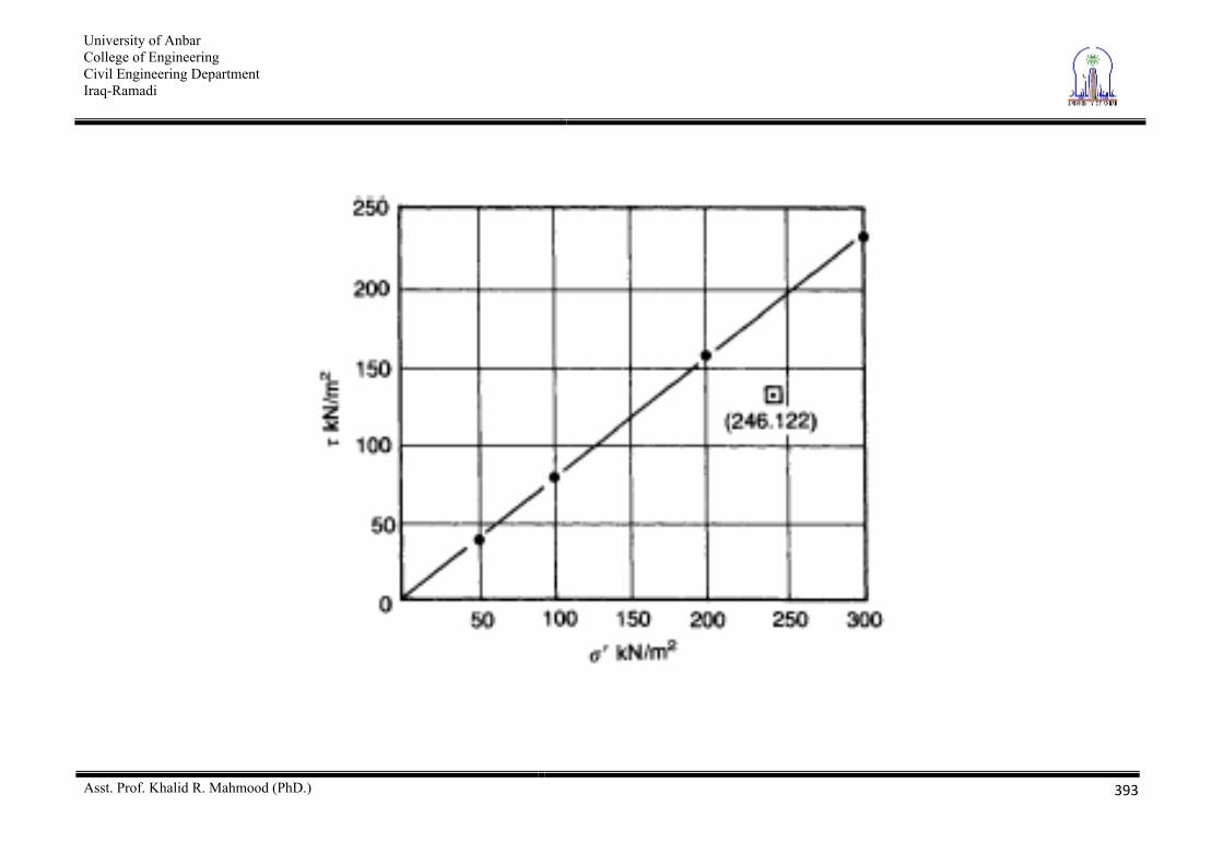
The values of shear stress at failure are plotted against the corresponding values of normal stress, as shown in Figure above. The failure envelope is the line having the best fit to the plotted points; in this case a straight line through the origin. If the stress scales are the same, the value of / can be measured directly and is 38o. The stress state =122kN/m2, / = 246 kN/m2 plots below the failure envelope, and therefore would not produce failure.
University of Anbar College of Engineering Civil Engineering Department Iraq-Ramadi
Asst. Prof. Khalid R. Mahmood (PhD.)
395
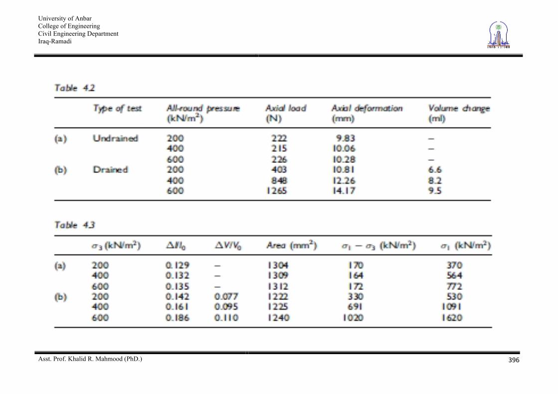
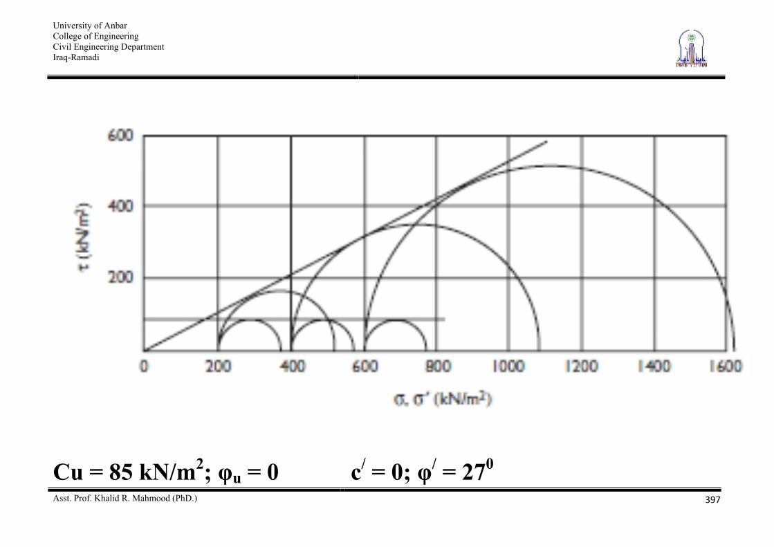
Example 2 The results shown in Table below were obtained at failure in a series of triaxial tests on specimens of a saturated clay initially 38mm in diameter by 76mm long. Determine the values of the shear strength parameters with respect to (a) total stress and (b) effective stress. Solution The initial values of length, area and volume for each specimen are: lo = 76mm; A0 = 1135mm2; V0 = 86 x 103 mm3
University of Anbar College of Engineering Civil Engineering Department Iraq-Ramadi
Asst. Prof. Khalid R. Mahmood (PhD.)
396
University of Anbar College of Engineering Civil Engineering Department Iraq-Ramadi
Asst. Prof. Khalid R. Mahmood (PhD.)
397
Cu = 85 kN/m2; u = 0 c/ = 0; / = 270
University of Anbar College of Engineering Civil Engineering Department Iraq-Ramadi
Asst. Prof. Khalid R. Mahmood (PhD.)
398
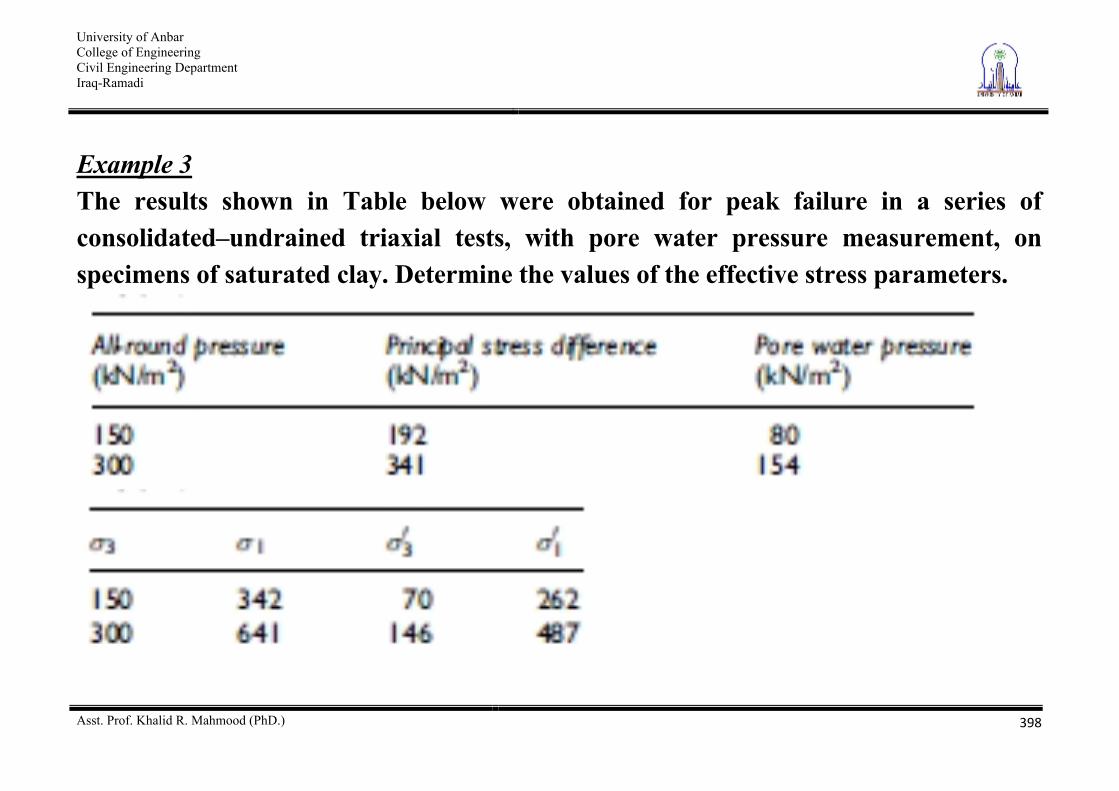
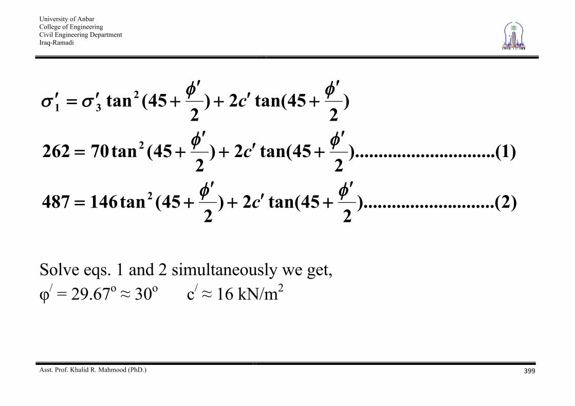
Example 3 The results shown in Table below were obtained for peak failure in a series of consolidated–undrained triaxial tests, with pore water pressure measurement, on specimens of saturated clay. Determine the values of the effective stress parameters.
University of Anbar College of Engineering Civil Engineering Department Iraq-Ramadi
Asst. Prof. Khalid R. Mahmood (PhD.)
399
)2.........(..........).........2
45tan(2)2
45(tan146487
)1.(....................).........2
45tan(2)2
45(tan70262
)2
45tan(2)2
45(tan
2
2
231
c
c
c
Solve eqs. 1 and 2 simultaneously we get, / = 29.67o 30o c/ 16 kN/m2