Embed Size (px)
Citation preview

HAL Id: hal-02160926https://hal.archives-ouvertes.fr/hal-02160926
Submitted on 20 Jun 2019
HAL is a multi-disciplinary open accessarchive for the deposit and dissemination of sci-entific research documents, whether they are pub-lished or not. The documents may come fromteaching and research institutions in France orabroad, or from public or private research centers.
L’archive ouverte pluridisciplinaire HAL, estdestinée au dépôt et à la diffusion de documentsscientifiques de niveau recherche, publiés ou non,émanant des établissements d’enseignement et derecherche français ou étrangers, des laboratoirespublics ou privés.
Strength measurement and rupture mechanisms of amicron thick nanocrystalline MoS2 coating using AFM
based micro-bending testsGuillaume Colas, Peter Serles, Aurélien Saulot, Tobin Filleter
To cite this version:Guillaume Colas, Peter Serles, Aurélien Saulot, Tobin Filleter. Strength measurement and rupturemechanisms of a micron thick nanocrystalline MoS2 coating using AFM based micro-bending tests.Journal of the Mechanics and Physics of Solids, Elsevier, 2019, 128, pp.151 - 161. �hal-02160926�
Strength measurement and rupture mechanisms of a micron thick
nanocrystalline MoS2 coating using AFM based micro-bending tests
G. Colas 1,2, P. Serles 1, A. Saulot 3, T. Filleter 1
1 Department of Mechanical and Industrial Engineering, University of Toronto, 5 King’s college
road, Toronto ON M5S 3G8, Canada
2 FEMTO-ST institute - Department of Applied Mechanics, Univ. Bourgogne Franche-Comté,
CNRS, 24 Chemin de l'Epitaphe, 25000 Besançon, France.
3 Université de Lyon, LaMCoS, INSA-Lyon, CNRS UMR 5259, France
Abstract
The present study focuses on the measurement of mechanical properties of a 1.1 µm thick
nanocrystalline MoS2 coating deposited by magnetron sputtering with a particular interest in the
strength of the coating. Mechanical strength is one of the most important properties to best predict
failure of the coating, especially in the case of dry contact lubricated systems in which the coating
of interest is often used. An Atomic Force Microscope based micro-bending experiment was
developed to measure the rupture strength of MoS2 micro cantilever-beams directly milled in the
coating using a Focused Ion Beam. Rupture strength of the MoS2 coatings was measured to be 728
± 88 MPa. Comparisons with nanoindentation was used to validate the micro-bending technique
via the statistically indifferent measurement of the Young’s modulus: 63.1 ± 5.0 GPa and
64.5 ± 4.0 GPa respectively. In depth study of the fractured beam surface and the microstructure
of the coating revealed that the surface roughness and the crystallite size can be directly correlated
to the rupture pattern. The crack was additionally shown to propagate within the nanocrystalline
network existing in the coating. Parallels with the tribological behaviour of the coating are drawn
and further confirm the lubrication mechanism described in previous studies.
Keyword:
MoS2, rupture strength, AFM bending test, focused ion beam, micro cantilever-beam
1 Introduction
Micron thickness coatings deposited through highly controlled synthesis methods such as physical
and chemical vapour deposition have demonstrated their suitability in a broad range of applications
including lubrication [1,2], machining [3], nuclear energy [4], and high-speed electronics [5].
While these coatings exhibit favourable functionally driven properties in this wide range of
applications, the understanding of their mechanical and structural characteristics remains, in many
cases, limited. Of particular interest is the synthesis and characterization of MoS2 coatings intended
to be used in tribological applications. In literature, significantly different MoS2 coating structures
are observed due to wide variances in deposition methods such as direct-current or radio-frequency
sputtering, and sputtering parameters such as chamber pressure and voltage [6–8]. Even the same
deposition parameters have been shown to produce different coating structures during subsequent
depositions due to variability in the system, sputtering target, or contaminants in the system [9].
This deposition variability directly influences the structure of MoS2 coatings; ranging from highly
organized columnar structures [6] to fully amorphous structures [10]. Studies on the mechanical
properties of MoS2 coatings also demonstrate a wide variance with Young’s modulus and hardness
values ranging from 50 to 170 GPa [3,10–12] and from 0.5 to 8 GPa [3,10–16] respectively.
Furthermore, there is a limited number of studies on both the rupture and the fracture strength of

the coatings. Measurement of those properties can be done via scratch testing, however finite
element modelling can be required to evaluate, from the experimental data, the stress intensity
factor related to fracture strength of the coating material [17]. Precise knowledge of these
parameters is very important for predicting coating failure through crack formation and
propagation, because it ultimately leads to particle detachment and coating delamination.
Most commonly, mechanical properties of micron-thin coatings are determined using
nanoindentation as it allows the measurement of hardness and Young’s modulus with minimal
sample preparation [18]. However, nanoindentation suffers from limitations linked to a number of
instrument and material parameters including: material pile-up and sink-in, substrate and
roughness effects, and system compliance which are known to strongly influence the measurement
reliability [18]. To overcome these limitations, a new approach has emerged throughout the last
15 years; high-precision milling of microstructures using a Focused Ion Beam (FIB) and deflecting
the structure through the use of nanoindentation techniques. These structures take a variety of
shapes including: free standing films [19,20]; micro pillars [21–23]; or micro-bridges and micro-
cantilever beams [4,23–29]. Of particular interest, micro-bending tests allow the study of several
mechanical properties – Young’s modulus, yield stress, strength, fracture toughness – relative to
the specific crystal orientation [4,28], the substructure of hierarchical architectures [26], or as an
average for the entire coating [4,27]. However, effective use of this technique requires high-
resolution measurements of the deflection, the applied force, and an exact knowledge of the
location of loading. Additionally, indenter penetration into the beam has to be considered as it can
lead to significant error in deflection values [24,30]. While this leads to complications for
nanoindenters and in situ Scanning Electron Microscope experiments (SEM), Atomic Force
Microscopy (AFM) can be a good solution as higher resolution in force, deflection, and accurate

loading location can be achieved. Micro-bending tests using AFM on submicron beams fabricated
by FIB [31] and chemical and wet etching processes [32–35] have allowed the study of stiffness,
bending strength, fracture toughness, and even fatigue toughness of materials.
In the present study, micro-cantilevers beams prepared by FIB-milling a 1.1 µm thick
nanocrystalline MoS2 coating were subjected to bending tests using an AFM. Through the use of
AFM deflection, high accuracy study of the Young’s modulus, rupture strength, and structural
fracture mechanism of the coating was conducted. The AFM micro-bending tests were additionally
validated via static and continuous stiffness nanoindentation measurements. As well, to better
understand the structural characteristics of the coating a Transmission Electron Microscopy (TEM)
study of the coating cross-sectional microstructure was also performed.
2 Experiments
2.1 Materials
The material of focus is a 1.10 ± 0.01 µm thick MoS2 coating deposited by radio-frequency
magnetron sputtering. The coating was sputtered on an N-doped Silicon wafer having a 285 nm
thick SiO2 oxide layer. The coating is space-qualified, i.e. it passed all tests imposed by space
agencies to be used in space, and it has been used for many years. It was deposited by Blösch AG.,
Grenchen, Switzerland.
This particular MoS2 coating has been previously described as a dense columnar-like
nanocrystalline structure (fibrous and vertically oriented) [36] based on the cauliflower aspect of
its surface, the deposition parameters, and fractured surfaces of delaminated portions [15,36–39].
Delamination and cracks have been observed under Scanning Electron Microscopy (SEM) and
their features suggest that rupture likely occurs at the interface between grains/columns [38].

However, to the author’s knowledge, there are neither studies on the rupture mechanism of such
MoS2 coatings nor reports of the strength of the interface between grains.
2.2 Micro-cantilever beam Preparation
MoS2 micro-cantilever beams were prepared using a Hitachi NB5000 high precision dual-beam
FIB and SEM. In order to achieve micro-cantilever beams consisting of freestanding MoS2, the
FIB-milling was performed without the protective metallic layer on the MoS2 coating which is
commonly used during FIB-milling. The beams were milled using a high-voltage Ga+ gun in a
three-stage process allowing for the creation of free-standing triangular cantilever beams as seen
in Figure 1a. First, 3 rectangular volumes are removed using a high energy beam (40 kV, 19.5 nA)
creating a rectangular structure of MoS2 coating with one end connected to the bulk of the coating.
Second, the undercut was performed at angles of either 45° or 58° on each side with a medium ion
beam energy (40 kV, 3.8 nA). At this stage, re-deposition of material, primarily made of Si and
Ga, accumulates on the undercut side of the micro-cantilever beam, therefore, a third low-energy
(40 kV, 0.8 nA) slow cleaning cut was performed to remove this re-deposited layer (cf. SI 1).
These beam energies were carefully selected to minimize the FIB induced damage and
amorphization of the coating [40–43] (SI 2). In total 11 micro-cantilever beams were successfully
characterized with dimensions varying from 9 to 15 µm in length, 1.4 to 2.2 µm in width, and 0.6
to 1.3 µm in height.
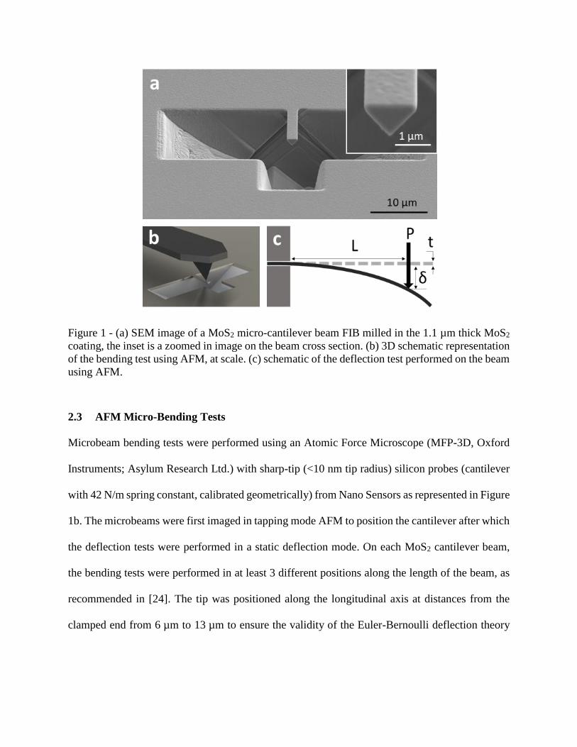
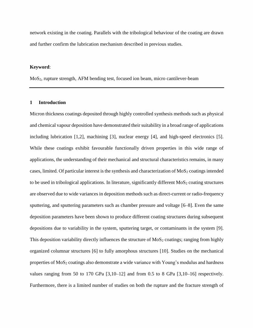
Figure 1 - (a) SEM image of a MoS2 micro-cantilever beam FIB milled in the 1.1 µm thick MoS2
coating, the inset is a zoomed in image on the beam cross section. (b) 3D schematic representation
of the bending test using AFM, at scale. (c) schematic of the deflection test performed on the beam
using AFM.
2.3 AFM Micro-Bending Tests
Microbeam bending tests were performed using an Atomic Force Microscope (MFP-3D, Oxford
Instruments; Asylum Research Ltd.) with sharp-tip (<10 nm tip radius) silicon probes (cantilever
with 42 N/m spring constant, calibrated geometrically) from Nano Sensors as represented in Figure
1b. The microbeams were first imaged in tapping mode AFM to position the cantilever after which
the deflection tests were performed in a static deflection mode. On each MoS2 cantilever beam,
the bending tests were performed in at least 3 different positions along the length of the beam, as
recommended in [24]. The tip was positioned along the longitudinal axis at distances from the
clamped end from 6 µm to 13 µm to ensure the validity of the Euler-Bernoulli deflection theory
[44]. At each location, incremental loading was performed from 0.5-10 µN with 5 deflections at
each load.
To create consistency between all beam sizes and loading conditions, the deflection test data was
converted into a stress-strain curve using the same model as Bechtle et al. [26]. In the calculation
of the beam deflection from the AFM measurements, no indentation depth correction was needed
because the tip does not indent the coating by more than 10 nm at a load of 20µN for an equivalent
beam deflection up to 800 nm. Equations (1) and (2) were used to calculate the stress 𝜎 and the
strain 휀 respectively. 𝑃 is the force applied at the loading point, located at a distance 𝐿 from the
clamped end. 𝑡 represents the thickness of the beam, 𝑤 the width, and 𝛿 is the beam deflection, as
schematized on Figure 1c. The coating is assumed to be macroscopically homogenous and
assumed to exhibit isotropic mechanical properties.
𝜎 =12∗𝑃∗𝐿
𝑤∗𝑡2 (1)
휀 =𝛿∗𝑡
𝐿2 (2)
The Young’s modulus E is calculated based on the linear fit of the curves in the 0 to 0.1% strain
range. The rupture strength Rm is determined as the stress at which the micro-cantilever beam
fractures.
2.4 Surface, Microstructure, and Compositional Analysis
The FIB micro-cantilever beam structures were analyzed using SEM (Hitachi SU3500) and
HRSEM (Hitachi SU5000) secondary electron imaging to determine beam dimensions and analyze
the surfaces after fracture. The coating surface morphology was studied using AFM in tapping-
mode. The characterization of the coating cross-section was performed using Transmission

Electron Microscopy (TEM) (Hitachi HF3300) and Scanning Transmission Electron Microscopy
(STEM) to study the microstructure at the nanoscale using backscatter, bright-field, and dark-field
micrographs. The TEM samples were prepared by a standard lift-out procedure using the same
high precision FIB with Ga+ ions accelerated to 40 kV. To preserve the structure of the MoS2
coating during FIB cross-sectional lift-outs, a 0.5 µm thick tungsten layer was deposited on the
coating prior to milling using ion beam plasma deposition from a WC2 gas. Two samples of 65 nm
and 76 nm in thickness respectively were examined in TEM and STEM using accelerating voltage
and emission currents of 300 kV and 5 µA respectively.
2.5 Nanoindentation Tests
The nanoindentation measurements were performed on an Anton Parr UNHT nanoindentor with a
diamond Berkovich tip to evaluate the Young’s modulus E and the Hardness H of the coating. In
addition to mechanical characterization of the coating, the measurement of the Young’s modulus
(depth variation, and bulk values) was used to compare with the cantilever beam tests results. In
total, 50 indentations were performed (two sets of 25) with the load pattern of: (1) load up to
500 µN at a speed of 3000 µN/min, (2) hold at 500 µN for 10 seconds to allow for stress relaxation,
(3) unload the contact at rate of 3000 µN/min. The extraction of E and H parameters was done
using the Oliver-Pharr method [45] considering a Poisson’s ratio of 0.27 [46]. Additionally, 12
measurements in the Continuous Stiffness Measurement (CSM) nanoindentation mode were
performed. CSM is a technique in which the indentation tip is continuously loaded and unloaded
throughout the depth of indentation thereby generating E and H values incrementally throughout
the depth [47,48]. To avoid instrument errors such as the woodpecker effect and low signal-to-
noise ratio, CSM parameters of 300 µN/min loading rate, 40 µN sinusoidal amplitude, and

maximum load of 2 mN were selected [49]. The woodpecker effect refers to “the tip losing contact
with the specimen during loading and unloading cycles during CSM” [49]. The surface function
of the tip was re-calibrated before each set of measurements to ensure coherence. After indentation,
the surface was imaged using the AFM in tapping mode to identify the effective contact area
(material pile-up or sink-in around the indent) which is used in E and H calculations.
3 Results
3.1 Cross-Sectional Electron Microscopy Characterization
The SEM image of the fractured coating cross-section (Figure 2a) shows a dense microstructure
with roughly vertically oriented grains. These grains appear to be in accordance with the dark field
STEM micrograph (Figure 2b) where large light gray vertically oriented regions of similar
magnitude are delimited by thin dark frontiers. The high-resolution STEM images (Figure 2 c,d,e)
show three distinct phases vertically distributed within the coating. The surface 47 ± 5 nm exhibits
a purely amorphous phase (Figure 2c) while the central bulk of the coating exhibits a
nanocrystalline phase embedded in an amorphous matrix (Figure 2d). These bulk nanocrystals are
vertically oriented within ±28º of the vertical axis and represent approximately 35% of the total
volume. Across 10 micrographs studied, a total of 189 nanocrystals were identified with widths of
13.1 ± 1.1 atomic layers (8.1 ± 2 nm; cMoS2 = 6.15 Å [50]) in the [001] direction and lengths of 12
± 4 nm in the [100] or [010] directions. The third phase exists as the bottom interface of the coating
with a height of 17 ± 4 nm and consists of similarly sized nanocrystals in an amorphous matrix as
in the bulk, but horizontally oriented within ±22º of the horizontal axis as seen in Figure 2e.
Figure 2 - (a) SEM image of the fractured cross-section of MoS2 coating. (b) to (e) TEM images
of the coating cross-section; (b) low magnification dark filed image of the entire coating thickness
with a small portion of the wafer substrate; (c) high magnification image of the coating top surface
showing an amorphous structure; (d) high magnification image of the coating bulk showing
vertically aligned crystallites; and (e) high magnification image showing the horizontally aligned
crystallites at the bottom interface with the SiO2 layer.
3.2 Nanoindentation
50 static mode indentations were conducted in two sets of 25 with indentation depths of 59 ± 1 nm
and 43 ± 4 nm respectively, both below the 10% thickness limit recommended for thin film
characterization [18]. The average Young’s modulus and hardness for this MoS2 coating obtained
from the all 50 measures were found to be E = 63.1 ± 5 GPa and H = 4.0 ± 0.7 GPa respectively

with no significant difference between the two measurement sets. The indentation loading curves
show a plateau when the load is maintained constant at 500 µN for 10s (Figure 3a). This plateau
is the effect of stress-induced creep which can be linked to viscoelasticity or viscoplasticity in the
material [18]. During unloading, the curve demonstrates hysteresis with a different slope as
compared to the loading curve (Figure 3a). However, surprisingly, the AFM topographic study of
the indented regions shows no significant indent (Figure 3b). To ensure proper location, one indent
at 2 mN load was performed at known distances from the 500 µN indents. Note that no significant
material pile-up or sink-in is detected in and around the high load indent (Figure 3b). The two sets
of 25 indentations which were performed show differences that are attributed to rounding of the
Berkovich tip between the measurements as evidenced by changes in the calibrated tip function
(cf. SI 3).
(a)
(b)
Figure 3 – (a) Examples of static mode indentation curves from the 1st and 2nd set of 25 indents
and AFM image of the surface after indentation; inset on the indentation curve gives the calculated
values of E and H over the 50 indents. (b) Example of CSM data obtained on pristine MoS2,
average value from the 2nd set of 25 indents from static mode indentation is shown for comparison.
The indentations performed in CSM mode (Figure 3b) were considered only up to an indentation
depth of 100 nm (<10% coating thickness) and the first 10 nm of indentation was negated due to
noise from the woodpecker effect. Interestingly, the MoS2 sample shows an increasing trend for E
and H values with respect to the indentation depth, in particular at depths below ~ 45 nm. As well,

for E there exists a transition from nonlinear to linear which corresponds with approximately
45 nm of depth. In comparison to the second set of static indentations (same tip function as in CSM
mode), at 43 nm of depth (corresponding to 500 µN load) both the E and H values are consistent
with the static mode values as reported in the inset of the graph on Figure 3a.
3.3 Micro-bending tests
The rupture strength (Rm) values for the five micro-cantilever beams that were successfully
fractured as well as the values of Young’s modulus (E) measured from nine beams are presented
in Table 1. The results show very consistent E values across the beams giving E = 64.5 ± 4.0 GPa.
Beam #10 demonstrated an AFM tip-sliding event (cf. SI 4) which might have modified the
tip/beam interface (e.g. transfer of material to the tip). This may explain the strong non-linearity
observed during the first 1% strain and consequently the outlier E value of 81.7 ± 4.5 GPa; beam
#10 was thus removed from the E average. As discussed in SI 5, contrary to E, the Rm of beam #5
does not appear to be as sensitive to the redeposition. Rm indeed stays within the range of values
defined by the other beams. Considering this additional Rm value to the five presented in Table
1, the average value is Rm = 728 ± 88 MPa. Although both E and Rm exhibit values within a
reasonably narrow range across the six beams considered, two groups tend to be observed if the
strain to rupture is considered. Indeed, four beams (#3, #5, #7 and #9) exhibit a strain to rupture in
the 1.2% - 1.3% range while beams #8 and #10 exhibit a strain to rupture higher than 2.4% as seen
in Figure 4a.
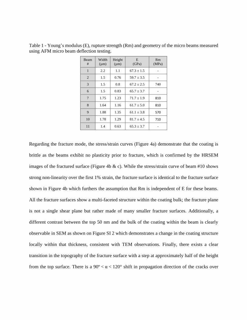
Table 1 - Young’s modulus (E), rupture strength (Rm) and geometry of the micro beams measured
using AFM micro beam deflection testing.
Beam
#
Width
(µm)
Height
(µm)
E
(GPa)
Rm
(MPa)
1 2.2 1.1 67.3 ± 1.5 -
2 1.5 0.76 59.7 ± 3.5 -
3 1.5 0.8 67.2 ± 2.5 740
6 1.5 0.83 65.7 ± 3.7 -
7 1.75 1.23 71.7 ± 1.9 810
8 1.64 1.16 61.7 ± 5.0 810
9 1.88 1.35 61.1 ± 3.8 570
10 1.78 1.29 81.7 ± 4.5 710
11 1.4 0.63 65.3 ± 3.7 -
Regarding the fracture mode, the stress/strain curves (Figure 4a) demonstrate that the coating is
brittle as the beams exhibit no plasticity prior to fracture, which is confirmed by the HRSEM
images of the fractured surface (Figure 4b & c). While the stress/strain curve of beam #10 shows
strong non-linearity over the first 1% strain, the fracture surface is identical to the fracture surface
shown in Figure 4b which furthers the assumption that Rm is independent of E for these beams.
All the fracture surfaces show a multi-faceted structure within the coating bulk; the fracture plane
is not a single shear plane but rather made of many smaller fracture surfaces. Additionally, a
different contrast between the top 50 nm and the bulk of the coating within the beam is clearly
observable in SEM as shown on Figure SI 2 which demonstrates a change in the coating structure
locally within that thickness, consistent with TEM observations. Finally, there exists a clear
transition in the topography of the fracture surface with a step at approximately half of the height
from the top surface. There is a 90º < α < 120° shift in propagation direction of the cracks over

few hundred nm distance around half the beam thickness before the second straight brittle fracture
finally occurs.
Figure 4 - (a) Stress/strain curves up to fracture of the beams on which rupture strength has been
measured, (b) & (c) fracture surface of the beam at the clamped end
4 Discussions
4.1 Stiffness & Ductility
Great consistency is observed between the indentation tests and the microbeam deflection tests,
which validates the AFM based deflection method. Both evaluation methods independently show
a Young’s modulus of approximately 64 GPa which compares well with the range of 50-170 GPa
reported in literature for MoS2 coatings [10–12]. This good correlation between both measurement
techniques supports the two major assumptions that were made in determining the Young’s
modulus. First, the assumption of isotropic mechanical properties through the entirety of the
coating which was made for the microbeams is validated as it provides a statistically indifferent E

value to nanoindentation which interacts only with the surface volume rather than the entire
volume. Second, the strong correlation between the results obtained by the two independent
techniques indirectly validates that the Poisson ratio for MoS2 is ν = 0.27. This value of Poisson’s
ratio is, to the authors’ knowledge, the only reported value measured for MoS2 and is the result of
a single crystal study conducted 40 years ago [46]. In the present study, only the nanoindentation
calculation uses the Poisson’s ratio to determine E while the microbeam deflection is independent
of this value thus indirectly confirming the validity.
The CSM measurements for the MoS2 coating show a nonlinear increasing trend for E which is
characteristic of porous materials response to such loading [51–53]. This supports well the already
suspected presence of porosities due to significant gas desorption during friction of the same
coating [36,54]. Since porosity promotes crack propagation, this further suggests that this is a low-
ductility brittle coating [55,56].
While the nanoindentation and micro-cantilever beam techniques provide statistically indifferent
values for E, as the micro-cantilever beams were FIB-milled without the protective tungsten layer
on the coating, concern of Ga+ ion induced amorphization was considered. In order to identify if
this occurred during the micro-cantilever beam manufacturing, two studies were performed to
compare the pristine coating to the area immediately surrounding the microbeam structures (SI 2).
Both investigations presented statistically indifferent results between the microbeam region and
the pristine coating, which suggests that the stray Ga+ ions in the present study had a negligible
impact on the microbeam evaluations.

4.2 Hardness
Regarding the hardness, the static nanoindentation results present a medium-high hardness value
of 4.0 GPa compared to 0.5-8 GPa for MoS2 coatings in literature [10–16]. This is likely due to
the nanocrystalline structure of the coating in accordance with the Hall-Petch effect [57]; the high
concentration of grain boundaries in nanocrystalline materials inhibit dislocation movement which
provides a material with high hardness and low ductility [58]. Although the nanocrystals are
embedded in an amorphous matrix, the hardness is nonetheless expected to be high as the
crystallites were measured to be 12 ± 4 nm in length which represents nearly the smallest size and
therefore maximum hardness before the breakdown of the Hall-Petch relationship [59].
Interestingly, while clear energy dissipation (usually linked to plasticity) is observed during static
mode indentation, no residual imprint was found (Figure 3a). Stempflé et al. noted the same effect
in indentation of graphite based 3rd body [60] and suggested that “the deformation energy during
the indentation is partly dissipated by structural changes of the elemental particles”. It is known
that under compression and shear stress (i.e. friction) amorphous MoS2 based material can
crystallize into crystalline MoS2 [61–63]. However, it could not be verified in the shallow
indentation case as studied here. Another assumption might be that the surface is able to elastically
recover while the stresses are transferred into the subsurface bulk of the coating. In the MoS2 case
studied here, there is a plateau during the time the load is kept constant, which means the indenter
continues penetrating in the material. This, in combination with the observed lack of indent
detected on the surface, suggests that the MoS2 coating is either demonstrating viscoelastic
properties or slow structural rearrangement such as the recrystallization mentioned above.

Such a behaviour could explain the low linear increase in hardness observed past the 45 nm
indentation depth. Altogether, evidence supports material “reconfiguration” rather than visco-
elasticity/plasticity.
4.3 Rupture Strength & Fracture
For six of the microbeams, deflection until fracture was achieved which ultimately demonstrated
brittle failure of the MoS2 coating. The resulting rupture strength provides a comparable value to
the MoS2 yield stress measured during nano-compression tests reported as 821 ± 141 MPa [64].
For a material exhibiting a brittle failure such as this, yield would result right before rupture, which
occurs at Rm = 728 ± 88 MPa in the present case. Additionally, the brittle fracture pattern of the
coating observed after the micro-bending rupture tests is consistent with the nano-indentation
results which suggest a brittle response of the MoS2 coating. This is also consistent with
observations from tribological tests during which brittle failure of the coating with partial
delamination has been seen [38]. Interestingly, results can be divided into two classes based on the
strain to failure. No clear explanation for these two regimes was found except for inherent
heterogeneities within the coating.
The multi-facetted morphology shown in the HRSEM images of the fracture surfaces (Figure 4b)
is consistent with the idea of a nanocrystalline structure within the coating; the crack propagation
within the coating would follow an intergranular fracture pattern along the variably oriented
nanocrystallites thus providing a multi-facetted morphology as seen herein. Additionally, the
general direction of fracture isn’t straight but presents two fracture directions oriented at
90º < α < 120º to each other. The transition between the two directions is a clear step located
approximately half of the thickness below the top surface of the beam. This location is slightly

below the theoretical neutral bending axis of a triangular prism, which divides the tensile and
compressive regimes above and below the neutral axis respectively. Similar fracture surface
morphology has been seen in the past for similar scale tests on Si, which corresponded to the
neutral bending axis [32]. Additionally, in porous brittle material, it has been shown that while
tensile stress creates unstable crack propagation leading to catastrophic failure, the propagation
quickly stabilizes under compressive stress and is rather contained [56]. However, in the MoS2
case studied herein, a difference in compressive regime versus tensile regime may not solely
explain such unusual fracture surface. The shift in crack propagation at half the beam height
however corresponds to the location of maximum shear stress, which would suggest that the bulk
of the MoS2 coating is sensitive to rupture by shear stress, even if the TEM appears to show
vertically aligned crystallites.
If Griffith’s theory is considered, it is possible to link the fracture stress to the crack length thanks
to equation (3). If Rm is used as the fracture stress 𝜎𝑓 and either the specific surface energy of
MoS2 (0.11 Nm-1) or the interlayer binding energy of MoS2 layers (0.22 Nm-1) [65] are used as
values for the surface energies of the crack 𝛾, then the crack length a determined from equation
(3) is within the 9 nm to 16 nm range. These values are consistent with peak-to-valley distances
measured on the top surface roughness of the beam (cf. SI 6), which was also demonstrated in the
Si microbeam case [32]. The roughness would thus act as a pre-crack. That means roughness can
most likely be at the origin of crack initiation, with the crack propagating within the MoS2
crystallites or at the interface between them.
𝜎𝑓 = √2𝛾𝐸
𝜋𝑎 (3)
It has been shown that friction between crystallites occurs due to the rupture of weak points at the
inter-crystallite interface [66]. Moreover, tests performed on 2D MoS2 crystals show that interlayer
sliding during bending occurs only when the number of layers is higher than 10 [65] while the
TEM study shows that nanocrystallites comprising the MoS2 coating studied herein are made of
13.1 ± 1.1 atomic layers on average. As a result, combination of soft interface fracture at the
interface between the nanocrystallites and interlayer sliding within the nanocrystallites is the most
likely to happen.
As a consequence of several different internal mechanisms, it is proposed that the rupture
mechanism of the micro-cantilever beam fabricated in the MoS2 coating is most likely a
combination of different phenomena governed by the roughness for crack initiation, the internal
porosities, and the nanocrystalline network for crack propagation until failure. The sensitivity to
shear stress (horizontal crack propagation in lower half) is suspected to be associated with
crystallite reconfiguration via possible reorientation of crystallites after rupture of weak points at
the inter-crystallite interface [66]. The morphology of the sheared surface appears flatter than, and
not as multifaceted as, the other two straight parts of the fractured surfaces.
4.4 Implications for Tribological Behaviour
During previous studies, the MoS2 coating studied herein has been tested as a dry lubricant coating,
which is one of its primary uses. The mechanical characterization conducted in the present study
plays a key role in better understanding the tribological behavior of this lubricant. The noted
nanocrystalline structure aids in explaining why this lubricant performs better than purely
amorphous coatings [1] or much harder coatings (H=8 GPa) [15]. The present study demonstrates
that the coating can resist compressive stresses more than tensile stresses as the nanocrystalline
network and porosities deter crack propagation throughout in the bulk under compression.
Therefore, during normal compressive loading, the coating will not crack as quickly. When sliding

occurs, shear can generate both tensile and compressive regimes in the coating. Due to the
crystalline and the porous networks coupled with sensitivity to shear stress, the propagation of the
fracture can easily, and quickly, shift direction from perpendicular to the friction track to parallel
to it without the crack propagating deep in the bulk. As the structure in the bulk of the coating is
comprised of grains of small size, such behavior could most likely lead to small particle
detachment. This ability to “feed” the contact by detaching small enough particles to be trapped in
the contact and lubricate it is the mechanism of 3rd body formation proposed in the previous
tribological studies performed on this specific coating [1,38]. Within all their MoS2 coatings,
Vierneusel et al. [15] obtained the best friction performances from a coating whose (i) surface
exhibits similar surface morphologies to the coating studied here, and (ii) hardness and
microstructure description that matches the present coating. However, TEM showed the presence
of a 47 nm thick amorphous layer on top of the coating. This does not affect the scenario
established above because under compression and shear, MoS2 can recrystallize [61–63].
5 Summary & Conclusion
This study focuses on the measurement of the rupture strength of a 1.1 µm thick nanocrystalline
MoS2 coating deposited by magnetron sputtering. An experimental protocol to perform bending
tests using AFM on triangular FIB-milled micro-cantilever beams has been developed to
characterize the mechanical properties of the coating. Alongside the micro-cantilever beams, an
in-depth analysis of the mechanical properties and rupture behaviour under bending conditions
was performed in conjunction with mechanical and structural analysis using nanoindentation,
SEM, and TEM instruments. Better understanding of the tribological behavior identified in
previous studies was thus possible. Furthermore, it is consistent with the assumed, but not

concretely proven, mechanisms of particle detachment in the 3rd body creation that is leading to
the success of the lubrication.
For the first time, the rupture strength of the MoS2 coating is measured to be Rm = 728 ± 88 MPa.
The micro-bending tests also confirm the brittle nature of the coating, which was indirectly
expected based on wear mechanisms observed in previous friction tests. The micro-bending tests
combined with nanoindentation and microstructural studies using TEM demonstrated both the
nanocrystalline and porous structure of the coating. Comparison with nanoindentation test results
additionally validated the microbeam deflection technique as the Young’s modulus determined
independently with both techniques presents statistically indifferent results: 63.1 ± 5.0 GPa and
64.5 ± 4.0 GPa respectively. This sets an overall average value of E = 63.8 ± 5 GPa. Additionally,
the consistency in the Young’s modulus measured with both techniques allows for the
confirmation that the Poisson’s ratio value of ν = 0.27 is accurate for MoS2.
This study has consequently determined both the microstructural (crystallinity, grain shape and
size, presence of porosity) and mechanical properties (E, H, Rm, ν) of this MoS2 coating thus
presenting a near-complete understanding of the coating for tribological testing. It also
demonstrated the influence of surface roughness and crystallite size in the coating resistance to
fracture. This therefore sets the groundwork for future studies such as numerical simulation of the
tribological behavior of the coating, structural compatibility with other thin-films for applications
such as batteries and semi-conductors, and microstructural understanding for applications such as
flexible electronics and nuclear energy.
Appendix
Information and DOI for our SI
Acknowledgement
The authors acknowledge support from the National Science and Engineering Research Council
of Canada (NSERC), the Erwin Edward Hart Professorship, the Connaught Fund at the University
of Toronto and the Canadian Foundation for Innovation (CFI). The authors would like to thank the
Ontario Centre for the Characterization of Advanced Materials (OCCAM) and especially Sal
Boccia and Jason Tam for their help in FIB-milling the micro-beams, FIB sample preparation for
TEM, and TEM characterization; Prof. C.V. Singh as well as Eric Nicholson from the Material
Science and Engineering Department of the University of Toronto for access and technical support
with the nanoindenter.
Funding
The National Sciences and Engineering Research Council of Canada;
The Ontario Ministry of Research and Innovation Early Researcher Award; the Erwin Edward
Hart Endowed Professorship; Canadian Foundation for Innovation
References
[1] G. Colas, A. Saulot, E. Regis, Y. Berthier, Investigation of crystalline and amorphous MoS2
based coatings: Towards developing new coatings for space applications, Wear. 330–331
(2015) 448–460. doi:10.1016/j.wear.2015.01.011.
[2] C. Wang, B. Li, X. Ling, J. Zhang, Superlubricity of hydrogenated carbon films in a nitrogen
gas environment: adsorption and electronic interactions at the sliding interface, RSC Adv.
7 (2017) 3025–3034. doi:10.1039/C6RA25505A.
[3] W.H. Kao, Tribological properties and high speed drilling application of MoS2-Cr coatings,
Wear. 258 (2005) 812–825. doi:10.1016/j.wear.2004.09.045.
[4] X. Zhao, R.M. Langford, J. Tan, P. Xiao, Mechanical properties of SiC coatings on spherical
particles measured using the micro-beam method, Scr. Mater. 59 (2008) 39–42.
doi:10.1016/j.scriptamat.2008.02.022.
[5] R.A. Street, Thin-film transistors, Adv. Mater. 21 (2009) 2007–2022.
doi:10.1002/adma.200803211.
[6] J. Moser, F. Levy, Crystal Reorientation and Wear Mechanisms in Mos2 Lubricating Thin-
Films Investigated By TEM, J. Mater. Res. 8 (1993) 206–213. doi:10.1557/jmr.1993.0206.
[7] J. Moser, F. Levy, Growth Mechanisms and Near-Interface Structure in Relation To
Orientation of Mos2 Sputtered Thin-Films, J. Mater. Res. 7 (1992) 734–740.
doi:10.1557/jmr.1992.0734.
[8] J.M. Martin, H. Pascal, C. Donnet, T. Le Mogne, J.L. Loubet, T. Epicier, Superlubricity of
MoS2: crystal orientation mechanisms, Surf. Coat. Technol. 68 (1994) 427–432.
[9] D.G. Teer, V. Bellido-Gonzales, H. Hampshire, Molybdenum-Sulphur Coatings, US
PATENT 6423419, 2002.
[10] X. Wang, Y. Xing, S. Ma, X. Zhang, K. Xu, D.G. Teer, Microstructure and mechanical
properties of MoS2/titanium composite coatings with different titanium content, Surf.
Coatings Technol. 201 (2007) 5290–5293. doi:10.1016/j.surfcoat.2006.07.124.
[11] N.M. Renevier, V.C. Fox, D.G. Teer, J. Hampshire, Properties of sputter-deposited
MoS2/metal composite coatings deposited by closed field unbalanced magnetron sputter
ion plating, Surf. Coatings Technol. 127 (2000) 24–37.
[12] T. Le Mogne, C. Donnet, J.M. Martin, A. Tonck, N. Millard‐Pinard, S. Fayeulle, N.
Moncoffre, Nature of super‐lubricating MoS 2 physical vapor deposition coatings, J. Vac.
Sci. Technol. A Vacuum, Surfaces, Film. 12 (1994) 1998–2004. doi:10.1116/1.578996.
[13] S. Watanabe, J. Noshiro, S. Miyake, Tribological characteristics of WS2/MoS2 solid
lubricating multilayer films, Surf. Coatings Technol. 183 (2004) 347–351.
doi:10.1016/j.surfcoat.2003.09.063.
[14] J. V. Pimentel, T. Polcar, A. Cavaleiro, Structural, mechanical and tribological properties
of Mo-S-C solid lubricant coating, Surf. Coatings Technol. 205 (2011) 3274–3279.
doi:10.1016/j.surfcoat.2010.11.043.
[15] B. Vierneusel, S. Tremmel, S. Wartzack, Effects of deposition parameters on hardness and
lubrication properties of thin MoS 2 films, Materwiss. Werksttech. 43 (2012) 1029–1035.
doi:10.1002/mawe.201200942.
[16] M.. Simmonds, A. Savan, E. Pflüger, H. Van Swygenhoven, Mechanical and tribological
performance of MoS2 co-sputtered composites, Surf. Coatings Technol. 126 (2000) 15–24.
doi:10.1016/S0257-8972(00)00521-1.
[17] K. Holmberg, H. Ronkainen, A. Laukkanen, K. Wallin, S. Hogmark, S. Jacobson, U.
Wiklund, R.M. Souza, P. Ståhle, Residual stresses in TiN, DLC and MoS2coated surfaces
with regard to their tribological fracture behaviour, Wear. 267 (2009) 2142–2156.
doi:10.1016/j.wear.2009.01.004.
[18] A.C. Fischer-Cripps, Nanoindentation, 2011. doi:10.1007/978-1-4419-9872-9.
[19] C.J. Shute, J.B. Cohen, Determination of yielding and debonding in Al-Cu thin films from
residual stress measurements via diffraction, J. Mater. Res. 6 (1991) 950–956.
doi:10.1557/JMR.1991.0950.
[20] Y. Xiang, X. Chen, T.Y. Tsui, J.I. Jang, J.J. Vlassak, Mechanical properties of porous and
fully dense low-κ dielectric thin films measured by means of nanoindentation and the plane-
strain bulge test technique, J. Mater. Res. 21 (2006) 386–395. doi:10.1557/jmr.2006.0045.
[21] P. Stoyanov, R. Merz, P.A. Romero, F.C. Wa, O.T. Abad, R. Gralla, P. Stemmer, M.
Kopnarski, M. Moseler, R. Bennewitz, M. Dienwiebel, Surface Softening in Metal À
Ceramic Sliding Contacts : An Experimental and Numerical Investigation, (2015) 1478–
1491. doi:10.1021/nn505968m.
[22] A.M. Korsunsky, M. Sebastiani, E. Bemporad, Residual stress evaluation at the micrometer
scale: Analysis of thin coatings by FIB milling and digital image correlation, Surf. Coatings
Technol. 205 (2010) 2393–2403. doi:10.1016/j.surfcoat.2010.09.033.
[23] T. Schwark, O. Kraft, R. Schwaiger, The boundaries of soft magnetic composites reveal
their complexity in compression and bending tests at the micro-scale, Mater. Sci. Eng. A.
684 (2017) 270–274. doi:10.1016/j.msea.2016.12.056.

[24] S. Massl, W. Thomma, J. Keckes, R. Pippan, Investigation of fracture properties of
magnetron-sputtered TiN films by means of a FIB-based cantilever bending technique, Acta
Mater. 57 (2009) 1768–1776. doi:10.1016/j.actamat.2008.12.018.
[25] M. Sebastiani, C. Eberl, E. Bemporad, G.M. Pharr, Depth-resolved residual stress analysis
of thin coatings by a new FIB-DIC method, Mater. Sci. Eng. A. 528 (2011) 7901–7908.
doi:10.1016/j.msea.2011.07.001.
[26] S. Bechtle, H. Ozcoban, E.T. Lilleodden, N. Huber, a. Schreyer, M. V. Swain, G. a.
Schneider, Hierarchical flexural strength of enamel: transition from brittle to damage-
tolerant behaviour, J. R. Soc. Interface. 9 (2012) 1265–1274. doi:10.1098/rsif.2011.0498.
[27] D. Di Maio, S.G. Roberts, Measuring fracture toughness of coatings using focused-ion-
beam-machined microbeams, J. Mater. Res. 20 (2005) 299–302.
doi:doi:10.1557/JMR.2005.0048.
[28] F. Iqbal, J. Ast, M. Göken, K. Durst, In situ micro-cantilever tests to study fracture
properties of NiAl single crystals, Acta Mater. 60 (2012) 1193–1200.
doi:10.1016/j.actamat.2011.10.060.
[29] J. Schaufler, C. Schmid, K. Durst, M. G??ken, Determination of the interfacial strength and
fracture toughness of a-C:H coatings by in-situ microcantilever bending, Thin Solid Films.
522 (2012) 480–484. doi:10.1016/j.tsf.2012.08.031.
[30] W. a Sasangka, C.L. Gan, D. Lai, C.S. Tan, C. V Thompson, Characterization of the
Young’s modulus, residual stress and fracture strength of Cu–Sn–In thin films using
combinatorial deposition and micro-cantilevers, J. Micromechanics Microengineering. 25
(2015) 035023. doi:10.1088/0960-1317/25/3/035023.
[31] D. Lu, A.H. Barber, Optimized nanoscale composite behaviour in limpet teeth, J. R. Soc.
Interface. 9 (2012) 1318–1324. doi:10.1098/rsif.2011.0688.
[32] T. Namazu, Y. Isono, T. Tanaka, Evaluation of size effect on mechanical properties of single
crystal silicon by nanoscale bending test using AFM, J. Microelectromechanical Syst. 9
(2000) 450–459. doi:10.1109/84.896765.
[33] S. Sundararajan, B. Bhushan, Development of AFM-based techniques to measure
mechanical properties of nanoscale structures, Sensors Actuators A. 101 (2002) 338–351.
[34] D. Choi, J. Jeon, P. Lee, W. Hwang, K. Lee, H. Park, Young’s modulus measurements of
nanohoneycomb structures by flexural testing in atomic force microscopy, Compos. Struct.
79 (2007) 548–553. doi:10.1016/j.compstruct.2006.02.023.
[35] W. Sumelka, T. Blaszczyk, C. Liebold, Fractional Euler-Bernoulli beams: Theory,
numerical study and experimental validation, Eur. J. Mech. A/Solids. 54 (2015) 243–251.
doi:10.1016/j.euromechsol.2015.07.002.
[36] G. Colas, A. Saulot, C. Godeau, Y. Michel, Y. Berthier, Decrypting third body flows to
solve dry lubrication issue - MoS2 case study under ultrahigh vacuum, Wear. 305 (2013)
192–204. doi:10.1016/j.wear.2013.06.007.
[37] P.D. Fleischauer, M.R. Hilton, R. Baeur, Effects of microstructure and adhesion on
performance of sputter-deposited MoS2 solid lubricant coatings, 1990.
[38] G. Colas, Utilisation raisonnée de contaminants pour caractériser la rhéologie des 1ers et
3ème corps solides : Application à la tribologie en ambiances spatiales, INSA de Lyon,
2013. https://tel.archives-ouvertes.fr/tel-00961216/.
[39] J. Moser, Composition and growth mode of MoSx sputtered films, J. Vac. Sci. Technol. A
Vacuum, Surfaces, Film. 12 (1994) 494. doi:10.1116/1.579157.
[40] F. Hofmann, E. Tarleton, R.J. Harder, N.W. Phillips, P.-W. Ma, J.N. Clark, I.K. Robinson,

B. Abbey, W. Liu, C.E. Beck, 3D lattice distortions and defect structures in ion-implanted
nano-crystals, Sci. Rep. 7 (2017) 45993. doi:10.1038/srep45993.
[41] D. Kiener, C. Motz, M. Rester, M. Jenko, G. Dehm, FIB damage of Cu and possible
consequences for miniaturized mechanical tests, Mater. Sci. Eng. A. 459 (2007) 262–272.
doi:10.1016/j.msea.2007.01.046.
[42] M.B. Lowry, D. Kiener, M.M. Leblanc, C. Chisholm, J.N. Florando, J.W. Morris, A.M.
Minor, Achieving the ideal strength in annealed molybdenum nanopillars, Acta Mater. 58
(2010) 5160–5167. doi:10.1016/j.actamat.2010.05.052.
[43] S. Rubanov, P.R. Munroe, FIB-induced damage in silicon, J. Microsc. 214 (2004) 213–221.
doi:10.1111/j.0022-2720.2004.01327.x.
[44] S.K. Park, X.L. Gao, Bernoulli-Euler beam model based on a modified couple stress theory,
J. Micromechanics Microengineering. 16 (2006) 2355–2359. doi:10.1088/0960-
1317/16/11/015.
[45] W.C. Oliver, G.M. Pharr, An improved technique for determining hardness and elastic
modulus using load and displacemenent sensing indentation experiments, J. Mater. Res. 7
(1992) 1564–1583.
[46] J.L. Feldman, Elastic constants of 2H-MoS2 and 2H-NbSe2 extracted from measured
dispersion curves and linear compressibilities, Solid State Commun. 19 (1976) viii.
doi:10.1016/0038-1098(76)90082-X.
[47] X. Li, B. Bhushan, A review of nanoindentation continuous stiffness measurement
technique and its applications, Mater. Charact. 48 (2002) 11–36. doi:10.1016/S1044-
5803(02)00192-4.
[48] J. Hay, P. Agee, E. Herbert, Continuous stiffness measurement during instrumented
indentation testing, Exp. Tech. 34 (2010) 86–94. doi:10.1111/j.1747-1567.2010.00618.x.
[49] G.M. Pharr, J.H. Strader, W.C. Oliver, Critical issues in making small-depth mechanical
property measurements by nanoindentation with continuous stiffness measurement, J.
Mater. Res. 24 (2009) 653–666. doi:10.1557/jmr.2009.0096.
[50] X. Li, H. Zhu, Two-dimensional MoS2: Properties, preparation, and applications, J. Mater.
1 (2015) 33–44. doi:10.1016/j.jmat.2015.03.003.
[51] D. Jauffrès, C. Yacou, M. Verdier, R. Dendievel, A. Ayral, Mechanical properties of
hierarchical porous silica thin films: Experimental characterization by nanoindentation and
Finite Element modeling, Microporous Mesoporous Mater. 140 (2011) 120–129.
doi:10.1016/j.micromeso.2010.09.004.
[52] X. Chen, Y. Xiang, J.J. Vlassak, Novel technique for measuring the mechanical properties
of porous materials by nanoindentation, J. Mater. Res. 21 (2006) 715–724.
doi:10.1557/jmr.2006.0088.
[53] A.A. Volinsky, J.B. Vella, W.W. Gerberich, Fracture toughness, adhesion and mechanical
properties of low-K dielectric thin films measured by nanoindentation, Thin Solid Films.
429 (2003) 201–210. doi:10.1016/S0040-6090(03)00406-1.
[54] G. Colas, A. Saulot, N. Bouscharain, C. Godeau, Y. Michel, Y. Berthier, How far does
contamination help dry lubrication efficiency?, Tribol. Int. 65 (2013) 177–189.
doi:10.1016/j.triboint.2012.12.011.
[55] C.G. Sammis, M.F. Ashby, The failure of brittle porous solids under compressive stress
states, Acta Metall. 34 (1986) 511–526. doi:10.1016/0001-6160(86)90087-8.
[56] S. Samborski, T. Sadowski, Experimental Investigations and Modelling of Porous
Ceramics, in: S. Samborski (Ed.), IUTAM Symp. Multiscale Model. Damage Fract.

Process. Compos. Mater., Springer, 2006: pp. 263–270.
[57] E. Gnecco, Fundamentals of Friction and Wear, Springer, 2007. doi:10.1007/978-3-540-
36807-6.
[58] A.A. Voevodin, J.S. Zabinski, C. Muratore, Recent Advances in Hard , Tough , and Low
Friction Nanocomposite Coatings New Directions in Hard Coatings, Tsinghua Sci. Technol.
10 (2005) 665–679.
[59] A.H. Chokshi, A. Rosen, J. Karch, H. Gleiter, On the validity of the Hall-Petch relationship
in nanocrystalline materials, Scr. Metall. 23 (1989) 1679–1684.
doi:10.1016/j.egypro.2009.02.265.
[60] P. Stempflé, J. Von Stebut, Nano-mechanical behaviour of the 3rd body generated in dry
friction - Feedback effect of the 3rd body and influence of the surrounding environment on
the tribology of graphite, Wear. 260 (2006) 601–604. doi:10.1016/j.wear.2005.03.021.
[61] K.J. Wahl, D.N. Dunn, I.L. Singer, Wear behavior of Pb-Mo-S solid lubricating coatings,
Wear. 230 (1999) 175–183. doi:10.1016/S0043-1648(99)00100-3.
[62] J.R. Lince, Tribology of co-sputtered nanocomposite Au/MoS2 solid lubricant films over a
wide contact stress range, Tribol. Lett. 17 (2004) 419–428.
doi:10.1023/B:TRIL.0000044490.03462.6e.
[63] F. Gustavsson, S. Jacobson, A. Cavaleiro, T. Polcar, Frictional behavior of self-adaptive
nanostructural Mo-Se-C coatings in different sliding conditions, Wear. 303 (2013) 286–
296. doi:10.1016/j.wear.2013.03.032.
[64] A. a. Tedstone, D.J. Lewis, R. Hao, S.-M. Mao, P. Bellon, R.S. Averback, C.P. Warrens,
K.R. West, P. Howard, S. Gaemers, S.J. Dillon, P. O’Brien, Mechanical Properties of
Molybdenum Disulfide and the Effect of Doping: An in Situ TEM Study, ACS Appl. Mater.
Interfaces. 7 (2015) 20829–20834. doi:10.1021/acsami.5b06055.
[65] D.-M. Tang, D.G. Kvashnin, S. Najmaei, Y. Bando, K. Kimoto, P. Koskinen, P.M. Ajayan,
B.I. Yakobson, P.B. Sorokin, J. Lou, D. Golberg, Nanomechanical cleavage of molybdenum
disulphide atomic layers, Nat. Commun. 5 (2014) 922872–922872.
doi:10.1038/ncomms4631.
[66] E.E. Hoffman, L.D. Marks, Soft Interface Fracture Transfer in Nanoscale MoS2, Tribol.
Lett. 64 (2016) 1–10. doi:10.1007/s11249-016-0743-2.