Embed Size (px)
Citation preview
STRENGTH DETERMINATION ANO SHEAR FAILURE MODES OF UNREINFORCED BRICK MASONRY WITH LOW STRENGTH MORTAR
Kariotis, J.C., Ewing, R.D., and Johnson, A.W. Co-Principal Investigators
ABK, A Joint Venture, El Segundo, California, USA
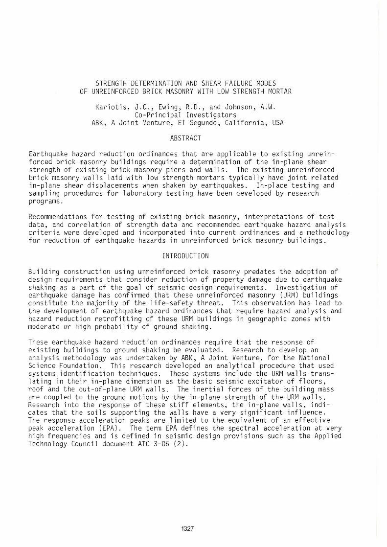
ABSTRACT
Earthquake hazard reduction ordinances that are applicable to existing unreinforced brick masonry buildings require a determination of the in-plane shear strength of existing brick masonry piers and walls. The existing unreinforced brick masonry walls laid with low strength mortars typically have joint related in-plane shear displacements when shaken by earthquakes. In-place testing and sampling procedures for laboratory testing have been developed by research programs.
Recommendations for testing of existing brick masonry, interpretations of test data, and correlation of strength data and recommended earthquake hazard analysis criteria were developed and incorporated into current ordinances and a met hodology for reduction of earthquake hazards in unreinforced brick masonry buildings.
INTRODUCTION
Building construction using unreinforced brick masonry predates the adoption of design requirements that consider reduction of property damage due to earthquake shaking as a part of the goal of seismic design requirements. Investigation of earthquake damage has confirmed that these unreinforced masonry (URM) buildings constitute the majority of the life-safety threat. This observation has lead to the development of earthquake hazard ordinances that require hazard analysis and hazard reduction retrofitting of these URM buildings in geographic zones with moderate or high probability of ground shaking.
These earthquake hazard reduction ordinances require that the response of existing buildings to ground shaking be evaluated. Research to develop an analysis methodology wa s undertaken by ABK, A Joint Venture, for the National Science Foundation. This research developed an analytical procedure that used systems identification techniques. These systems include the URM walls translating in their in-plane dimension as the basic seismic excitator of floors, roof and the out-of-plane URM walls. The inertial forces of the building mass are coupled to the ground motions by the in-plane strength of the URM walls. Research into the response of these stiff elements, the in-plane walls, indicates that the soils supporting the walls have a very significant influence. The response acceleration peaks are limited to the equivalent of an effective peak acceleration (EPA). The term EPA defines the spectral acceleration at very high frequencies and is defined in seismic design provisions such as the Applied Technology Council document ATC 3-06 (2).
1327
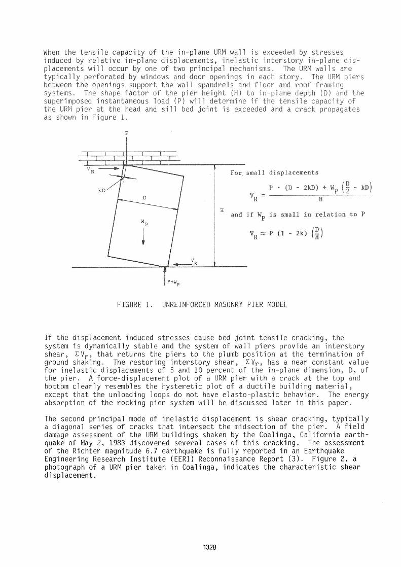
When t he t ensi le capacity of t he i n-p lane URM wall is exceeded by stresses induced by relat i ve in- pl ane displ acements, ine l asti c interst ory i n-plane displac ement s will occur by one of t wo pri ncipal mechanisms. The URM walls are t yp icall y perf orated by wi ndows and door openings in each story. The URM piers between the opening s support the wall spandrels and floor and roof framing systems. The shape f actor of t he pi er height (H ) to in-plane depth (O) and the superimposed i nstant aneous load (P) will determine if the tensile capacity of the URM pi er at the head and sill bed joint is exceeded and a crack propagates as shown in Figure 1.
p
For small displacements
P • (D - 2kD) + Wp (~ - kD ) V = -------=;---'-----
R H
H and if Wp i s small in relation to P
VR ~ P (1 - 2k ) (~ )
FIGURE 1. UNREI NFORCEO MASONRY PIER MOOEL
If the disp l acement induced str esses cause bed joint t ensile cracking, the system i s dynamically stabl e and the system of wal l piers provide an i nter st ory shear, EV , that r etu rns t he piers to t he plumb posit i on at the termination of ground shak i ng . The r estoring interstory shear, EVr , has a near constant value for i nel asti c dis placements of 5 and 10 percent of t he i n-plane dimension, O, of the pier. A forc e-displ acement plot of a URM pier with a crack at the t op and bo ttom cl ear ly r esembl es the hyst ereti c plot of a ductile bu i lding mater i al, except t hat the un l oadi ng l oo ps do not have elasto-plastic behavior . The energy absorption of the r ock ing pier system will be discussed later in th is paper.
Th e second principal mod e of i nelasti c displ acement is shear cracki ng, t ypi cally a diagonal series of cracks that i nter sect the mi dsect ion of the pi e~. A f ield damag e assessment of the URM bui l ding s sha ken by the Coali nga , Cal i forn i a earth quake of May 2, 1983 discovered several cases of thi s cracking . The assessment of the Richter magnitude 6.7 earthquake is fully reported in an Earthquake Engineering Research Institute (EERI) Reconnaissance Report (3) . Figure 2, a photograph of a URM pier taken in Coalinga, indicates the characteristic shear displacement.
1328
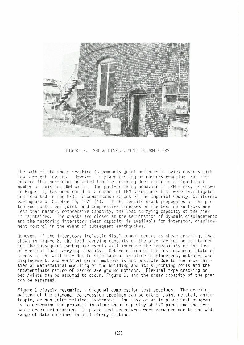
FIGURE 2. SHEAR DISPL AC EMENT IN URM PIERS
The path of the shear cracking is commonly joint oriented in brick masonry with low strength mortars. However, in-place testing of masonry cracking has discovered that non-joint oriented tensile cracking does occur in a significant number of existing URM walls. The post-cracking behavior of URM piers, as shGwn in Figure 1, has been noted in a number of URM structures that were invest ig ated and reported in the EERI Reconnaissance Report of the Imperial County, California earthquake of October 15, 1979 (4). If the tensile crack propagates on the pier top and bottom bed joint, and compressive stresses on the bearing surfaces are less than masonry compressive capacity, the load carrying capacity of the pier is maintained. The cracks are closed at the termination of dynamic displacements and the restoring interstory shear capacity is available for interstory displacement control in the event of subsequent earthquakes .
However, if the inters tory inelastic displacement occurs as shear cracking, that shown in Figure 2, the load carrying capacity of the pier may not be maintained and the subsequent earthquake events will increase the probability of the l oss of vertical load carrying capacity. Determination of the instantaneous state of stress in t he wa ll pier due to simultaneous in-plane displacement, out-of - plane displacement, and vertical ground motions is not possible due to the uncertainties of mathematical modeling of the building and its supporting soils and the indeterminate nature of earthquake ground motions. Flexural type cracking on bed joints can be assumed to occur, Figure 1, and the sh ear capacity of the pier can be assessed.
Figure 1 closely resembles a diagonal compression test specimen. The cracking pattern of the diagonal compression specimen can be either joint related, anisotropic, or non-joint related, isotropic. The tas k of an in-place test program is to determine the probable in-plane shear capacity of URM piers and the probable crack orientation. In-place test procedures were required due to the wide range of data obtained in preliminary testing.
1329
CURRENT TESTING PROCEDURE
Observation of shear cracking in unreinforced brick masonry with low strength mortars indicates the capacity is related to the adhesive and cohesive shear strength of the mortar. Adhesive strength is defined as bond strength of the mortar to the brick unit. Cohesive strength of the mortar is defined as the internal shear strength of the mortar. Observed data and research by Drs. Johnson and Thompson (5) indicates the shear capacity of the masonry assemblage is strongly influenced by the force component normal to the bed joints.
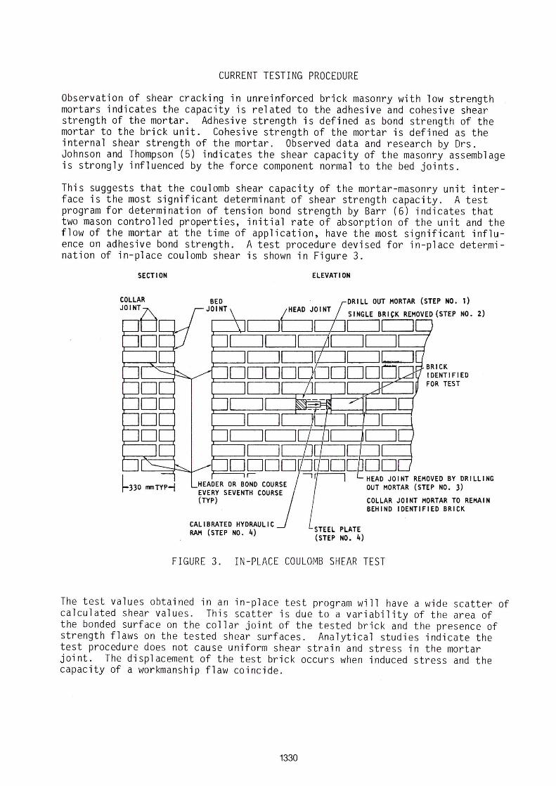
This suggests that the coulomb shear capacity of the mortar-masonry unit interface is the most significant determinant of shear strength capacity. A test program for determination of tension bond strength by Barr (6) indicates that two mason controlled properties. initial rate of absorption of the unit and the flow of the mortar at the time of application. have the most significant influence on adhesive bond strength. A test procedure devised for in-place determination of in-place coulomb shear is shown in Figure 3.
SECTION
I
HEAOER OR BONO COURSE EVERY SEVENTH COURSE (TYP)
CALIBRATEO HYORAULIC RAH (STEP NO. 4)
ELEVATION
ORILL OUT MORTAR (STEP NO. 1)
SINGLE BRICK REMOVE0 (STEP NO. 2) ,...--.,1--'1 11 I
STEEL PLATE (STEP NO. 4)
HEAO JOINT REMOVE0 BY ORILLING OUT MORTAR (STEP NO. 3)
COLLAR JOINT MORTAR TO REMAIN BEHINO IOENTIFIEO BRICK
FIGURE 3. IN-PLACE COULOMB SHEAR TEST
The test values obtained in an in-place test program will have a wide scatter of calculated shear values. This scatter is due to a variability of the area of the bonded surface on the collar joint of the tested brick and the presence of strength flaws on the tested shear surfaces. Analytical studies indicate the test procedure does not cause uniform shear strain and stress in the mortar joint. The displacement of the test brick occurs when induced stress and the capacity of a workmanship flaw coincide.
1330
In two buildings of 1910 vintage in the city of San Diego, California, displacement of the test brick did not occur prior to failure of the jack bearing surfaces. Eight inch round cores and sawn diagonal compression specimens had nonjoint oriented failure similar to masonry specimens that were constructed and tested in recent research programs. The tensile values determined from these tests had a much more normal distribution of data. The general interpretation of this data distribution is that the distribution of strength reduction flaws in critical stress zones of the test specimen is much more uniform than that determined by individual brick testing. However, this does indicate that the size of the sample should be as large as can be handled.
ANALYSIS OF THE SHEAR TESTING PROGRAM
The test programs conducted in URM buildings that were scheduled for demolition are fully reported in references (1), Appendices C and D, and reference (7). The correlation of data obtained by test procedures used in 1978 and 1983 was adequate to determine techniques for interpretation of in-place shear testing. The need to utilize existing masonry as the test samples restricts the rigorous determination of masonry properties. However, the uncertainty associated with URM tensile strength is no more or less than the uncertainties of structural response to earthquake motions or the uncertainty of real time combination of three dimensional ground motions.
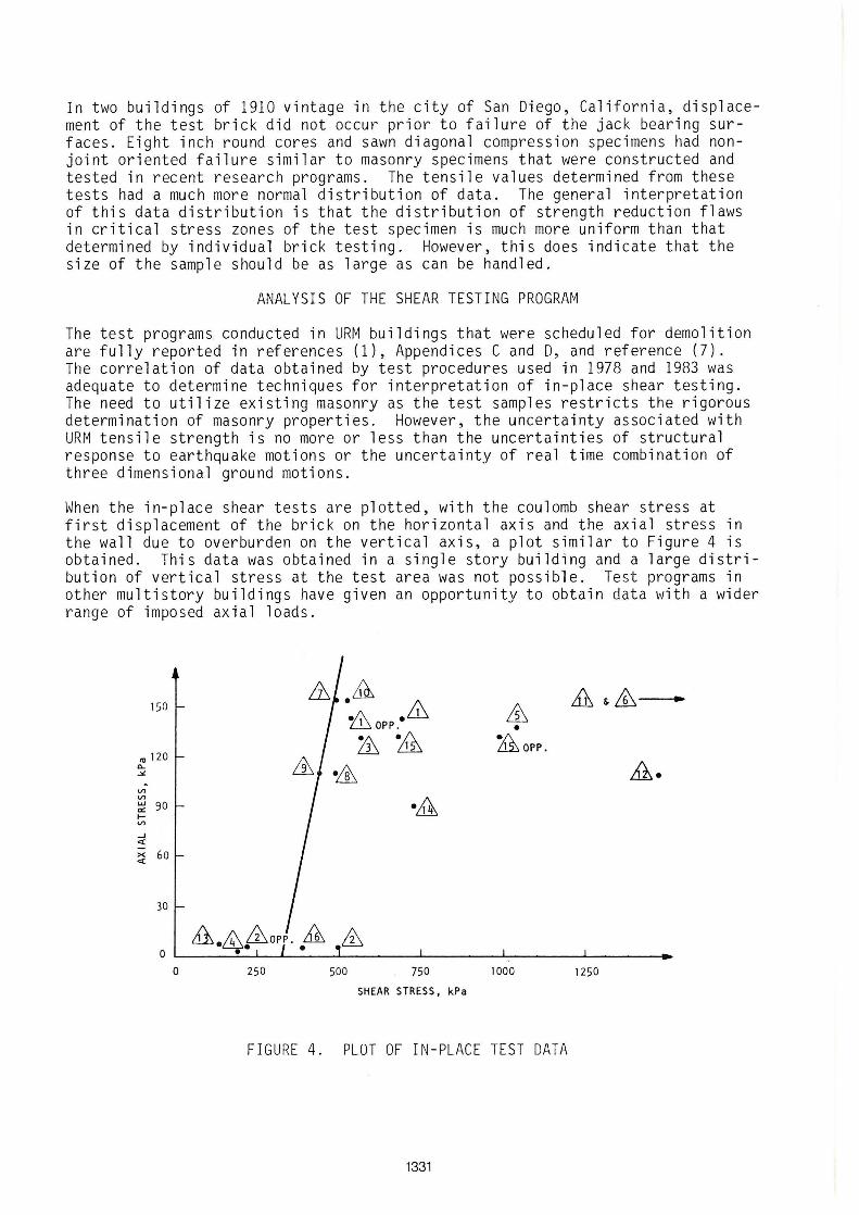
When the in-place shear tests are plotted, with the coulomb shear stress at first displacement of the brick on the horizontal axis and the axial stress in the wall due to overburden on the vertical axis, a plot similar to Figure 4 is obtained. This data was obtained in a single story building and a large distribution of vertical stress at the test area was not possible. Test programs in other multistory buildings have given an opportunity to obtain data with a wider range of imposed axial loads.
J1 M&ffi .. 150 ·m .ffi &
OPP. •
'" 120 ill Li1 L11 OPP.
~ .& .11. ~
-V) V) • .61 w 90 a: l-V)
..J
::: >< 60 <t
30
A.~fooPP .• M, ffi o
o 250 500 750 1000 1250
SHEAR STRESS, kPa
FIGURE 4. PLOT OF IN-PLACE TEST DATA
1331
The analysis of the t~sting programs assumes the coulomb shear capacity of the mortar-brick interface can be expressed by:
Va = k (r • vt + 0 P/A)
where: k r
vt
0
P/A
=
constant < 1 to adjust capacity for workmanshi p fl aws. reduction factor to adjust tested values for probable bonding on the collar joint. bed joint shear stress as determined by in-place testing. v is reduced to an equivalent shear at zero axial load normal to fhe bed joint. factor to account for increase in shear due to loads normal to the bed joint. axial stress normal to the bed joint.
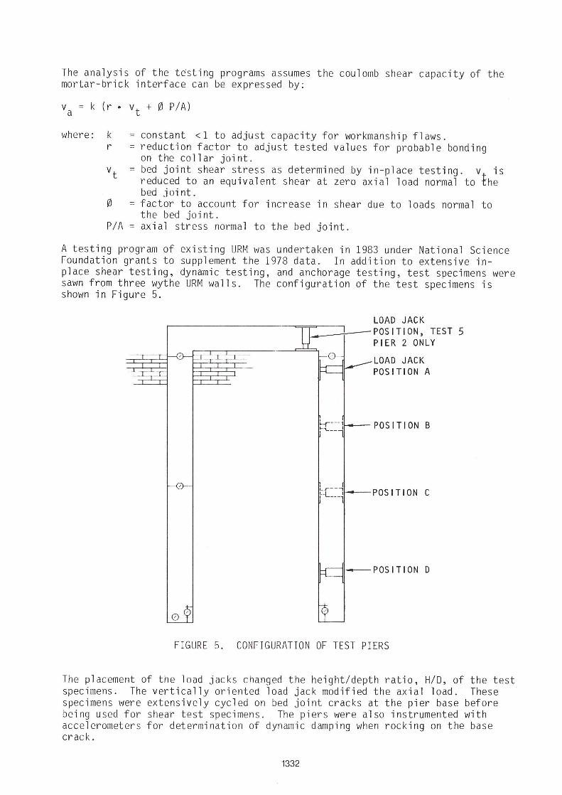
A testing program of existing URM was undertaken in 1983 under National Science Foundation grants to supplement the 1978 data . In addition to extensive inplace shear testing, dynamic testing, and anchorage testing, test specimens were sawn from three wythe URM walls. The configuration of the test specimens is shown in Figure 5.
LOAD JACK I~_-;--- POS I TI ON, TEST 5
, ,
PIER 2 ONLY
LOAD JACK POSITION A
~,- --1 POS I T I ON B ~""l.. __ I
t-r--j POS I T I ON C I -L ___ ,
I~--''--- POS I T I ON D
FIGURE 5. CONFIGURATION OF TEST PIERS
The placement of the load jacks changed the height/depth ratio, H/O, of the test specimens. The vertically oriented load jack modified the axial load . These specimens were extensi vely cycled on bed joint cracks at the pier base before being used for shear test specimens. The piers were also instrumented with accelerometers for determination of dynamic damping when rocking on the base crack.
1332
Data from the 1978 test program and the 1983 program was used to estimate the "r" factor. A large number of the 1978 tests separated the test brick on the collar joint prior to testing. Comparison of the in-place shear test values to diagonal compression test specimens sampled from the same building indicated that the "r" factor approximated 3/4. This reduction factor is the same as if the face area of the brick on the collar joint is deducted from the surfaces available for mortar bond.
The determination of Vt from the test data requires that 0, the factor defining the effect of normal stress on the shear plane, be estimated first. Determination of 0 independent of flaw effects is very difficult. A test program in a three story building gave an opportunity to obtain a uniform distribution of axial stressin the test zones. A series of in-place tests in this building of 1900 vintage indicated that if the data is plotted as shown in Figure 4, and horizontal data scatter due to flaw effect is assumed to be included in the determination of 0, 0 mean is calculated as 2.4 with a standard deviation of 1.3. This calculation determined vt by tests where PIA is near zero. The data obtained in this zone had a mean Vt of 330 kPa and a standard deviation of 95 kPa. To further investigate the probable values of 0, the test specimens shown in Figure 5 were displaced laterally on previously cracked surfaces. When cohesion had been reduced to zero by flexural cracks, 0 values calculated had a range of 1.5 to 1.75 on original surfaces without prior horizontal displacement. When the specimen was subjected to several cyclic shear displacements, the minimum calculated value of 0 was 1.15. In-place shear tests indicate that disregarding the adhesion strength effect on coulomb shear will not have a significant effect on determination of acceptable shear capacity in URM walls of very low strength mortars. However, this will significantly underestimate the shear capacity in moderate strength mortar specimens. Shear displacement of a test brick or a test specimen is not a brittle failure in mortars with low to moderate adhesive and cohesive strengths. Surprisingly, jacking loads must be increased for increasing shear displacement after first observed movement in the majority of in-place shear tests. Large scale specimens were cyclically displaced on cracked surfaces without significant reduction of test load.
The test data is reduced to equivalent zero axial stress by assuming 0 = 1.0. The value Vt is taken as the twentieth percentile value of the data in lieu of use of a mean reduced by a multiple of the standard deviation of the test data. The estimation of Vt by use of this procedure is simpler and adequate, considering the uncertainty of ground motions and mathematical modeling.
The factor "k" compares to the capacity reduction factor used in strength design of reinforced concrete. An estimate of its value was made from data obtained by large scale tests, after estimates of r, Vt and 0 were determined. This reduction factor includes the lesser contribution of the inner wythes to the shear capacity of the multiwythe wall and the increased probability that a workmanship flaw will occur in the critical stress zone of a large pier. Finite element studies indicate that there is a large near-uniform biaxial stress zone in the center of the typical pier, Figure 1. Interpretation of fracture mechanics indicates the shear crack initiates at a flaw and propagates immediately through the mid-section of the pier in the pattern observed in Figure 2. This crack propogation was observed to be sudden and with an audible sound. Correlation of full scale tests with the assumed equation for determination of acceptable shear, va ' estimated k as 3/4. The standard deviation of the test data was 0.11. If only the data from the 1978 tests is used the mean value of k is 0.78. If only the data from the 1983 tests is used the mean value of k is 0.73 .
1333
ANALYTICAL STUOIES
The analysis of the testing program utilized finite element studies of the 1983 test specimens and of varied pier configuration. It was recognized that brick masonry is not isotropic even if shear crack patterns are not joint related. Finite element studies that model the unit and the mortar joints independently indicate that stress concentrations occur at the intersection of head and bed joints. The analytical finite element studies were used to indicate the general state of biaxial stress in piers with shape factors that are common to the inventory of existing URM buildings. These studies indicated that for piers with shape factors, H/O, of 0.5 and greater, the shear, T~V' is estimated as 1.5 V divided by the gross in-plane area of the pier. For wall piers with shape factors of less than 0.5, the shear is estimated as 1. 0 V divided by the gross in-plane area of the wall.
The finite element studies of the piers confirmed that calculations based on usual bending formulas do not predict bed joint tension at the top and bottom of wall piers. The large scale tests gave visual evidence that the propagation of a flexural crack across the pier section is not sudden. The force-d i splacement plotting gave a better indication of the occurrence of cracking than visual observations .
Analytical studies of URM piers indicate that the probability of compressiv e failure of the toe of a pier in a rocking mode, Figure I, is extremely small . The apparent compressive modulus of elasticity of low strength mortar is very low . The testing displaced piers to a top displacement of six to eight times elastic limito The observed length of the compression surface was not linear with top displacement. This behavior is attributed to a nearly constant stress with increasing strain . Stress-strain plots such as this are noted for low strength concrete specimens.
CURRENT RECOMMENOATIONS
The Methodology, reference (1), recommends that the acceptabl e unit shear strength of a URM pier be calculated as:
va 3/4 (3/4 vt + P/A)
where: Vt is the twentieth percentile of the in-place shear tests reduced to an equivalent shear at zero axial load
P is the axial load in the wall pier
A is the gross area of the pier
P and A are in stress units consistent with vt Structural response shear on the pier is calculated as 1.5 V
A
where: V is response shear assigned to the pier by rigidity analysis. For the determination of the relative rigidity, pier stiffness is taken as H/O if piers are of equal thickness and identical material.
1334
The analysis of URM walls that are pier and spandrel systems is difficult due to modeling uncertainties . If the pier systems have a shape factor and applied loads such that tension cracks develop on the bed joint at the top and bottom of the pier, the in-plane shear capacity can be readily compared to the restoring shear Vr , Figure 1. Vr cannot be exceeded in this pier system and is independent of structural response. A corollary of this behavior is the shear design of a reinforced concrete member for the sum of yield moments at the ends. If the shear capacity of the pier is less than Vr , then shear displacement within the pier section is probable and the upper bound of structural response of the URM wall must be considered.
Cracking can also occur in spandrels in a perforated wall instead of in the piers. This URM wall performance is similar to coupled shear walls. This probability can be reduced by installation of ties of substantial stiffness at floor levels if such ties do not exist in the existing structural system. However, when such spandrel cracking has been observed in investigation of URM earthquake damage, the life-safety threat posed has been minimal. Lintels or arches generally contain the cracked spandrel and the load carrying capacity of the URM piers is not diminished.
DYNAMIC CHARACTERISTICS OF ROCKING PIERS
The observation of URM buildings shaken by moderate to large earthquakes notes that the absence of diagonal cracking in perforated wall systems cannot be rationalized by in-plane strengths. Special investigation of probable tensile bed joint cracking at the top and bottom of piers was made in the inventory of URM buildings after the Imperial County, California earthquake of October 15, 1979, reference (4). This investigation indicated that the bed joint crack was observable only in painted masonry surfaces. Unpainted masonry piers that had identical relative displacements did not have visible cracking. The roughness of interface of the mortar and brick concealed the crack. This was also noted in large scale test specimens that were examined after cracking displacements.
As previously discussed, the force-displacement plot of a cracked pier system has a loading envelope nearly identical to a yielding ductile member. The unloading cycle does not have an elasto-plastic loop that indicates energy absorption. Studies by Professor Chopra (8) indicated that energy loss from the rocking block system is related to a a coefficient of restitution, that is less than one, upon crack closing.
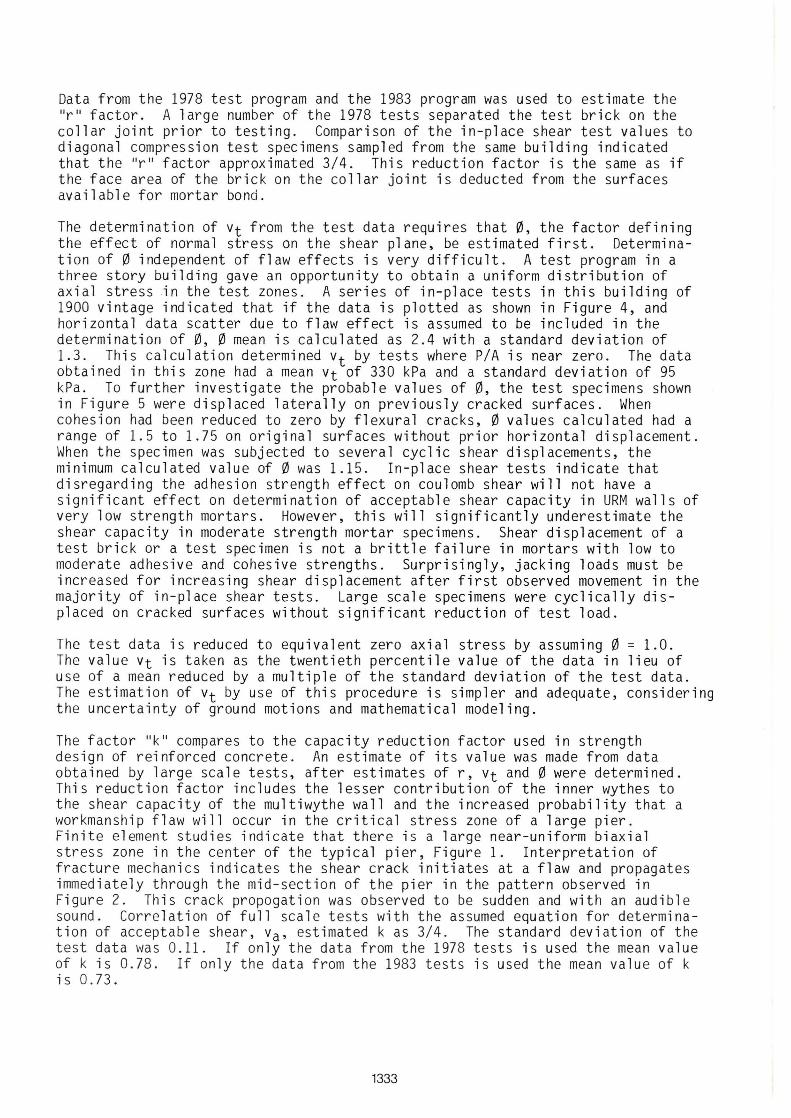
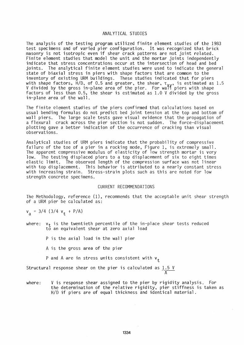
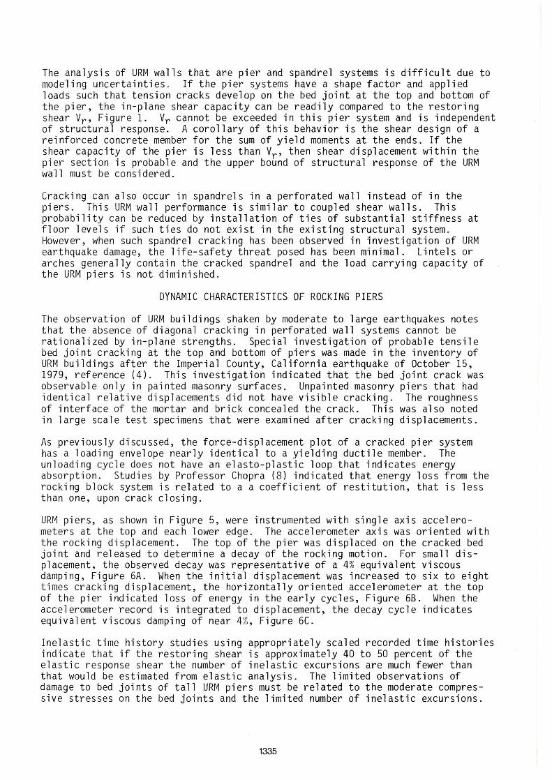
URM piers, as shown in Figure 5, were instrumented with single axis accelerometers at the top and each lower edge. The accelerometer axis was oriented with the rocking displacement. The top of the pier was displaced on the cracked bed joint and released to determine a decay of the rocking motion. For small displacement, the observed decay was representative of a 4% equivalent viscous damping, Figure 6A. When the initial displacement was increased to six to eight times cracking displacement, the horizontally oriented accelerometer at the top of the pier indicated loss of energy in the early cycles, Figure 68. When the accelerometer record is integrated to displacement, the decay cycle indicates equivalent viscous damping of near 4%, Figure 6C .
Inelastic time history studies using appropriately scaled recorded time histories indicate that if the restoring shear is approximately 40 to 50 percent of the elastic response shear the number of inelastic excursions are much fewer than that would be estimated from elastic analysis. The limited observations of damage to bed joints of tall URM piers must be related to the moderate compressive stresses on the bed joints and the limited number of inelastic excursions.
1335
; 00 0 . 40 .. ..
~ I I~ , .. J(t:OIIDS
FIGURE 6A. DYNAMIC PIER TEST DATA RUN 2, STATION B (HOR)
1I11( 1. S ' 0 D
FIGURE 6B. DYNAMIC PIER TEST DATA RUN 6, STATION A (UP)
l . o '.1. 1-10 1 . 10 t." 4.40 4 · 10 ' .1. ' . "0 " . 00 ".t.
;I~ ~Iª FIGURE 6C. DYNAMIC PIER TEST DATA RUN 6, STATION C (UP)
1336
ACKNOWLEDGEMENT
This research was conducted by ABK, A Joint Venture, for the National Science Foundation under Contract No. NSF-C-PFR-78-19200 and Grant No. CEE-8100532. The Joint Venture ABK consists of the three firms, Agbabian Associates, S.B. Barnes & Associates, and Kariotis & Associates, all in the Los Angeles area. The principal investigators for the three firms are R.D. Ewing, A.W. Johnson, and J.C. Kariotis. Dr. J.B. Scalzi served as Technical Director of this project for the National Science Foundation and maintained scientific and technical liaison with the joint venture throughout all phases of the research programo His contributions and support are greatly appreciated.
REFERENCES
(1) ABK, A Joint Venture, Methodology for Mitigation of Seismic Hazards in Existing Unreinforced Masonry Buildings. The Methodology, ABK-TR-08, El Segundo, California, USA, 1984.
(2) Applied Technology Council (ATC), Tentative Provisions for the Development of Seismic Regulations for Buildings, ATe 3-06, Palo Alto, California, USA, 1978.
(3) Earthquake Engineering Research Institute (EERI), Coalinga, California Earthquake of May 2, 1983, Reconnaissance Report, Berkeley, California, USA, 1979.
(4) EERI, Imperial County, California, Earthguake of October 15, 1979, Reconnaissance Report, Berkeley, California, USA, 1979.
(5) Johnson, F.B. and Thompson, J.N., The Development of Diametral Testing Procedures to Provide a Measure of Strength Characteristics of Masonry Assemblages, International Conference on Masonry Structural Systems, Austin, Texas, USA, 1967.
(6) Baur, J.C., Compression and Tension Bond Strength of Small Scale Masonry Specimens, M.S. Thesis, University of Colorado, Boulder, Colorado, USA, 1977.
(7) Schmid, B., Kariotis, J.C., and Schwartz, E., Tentative Los Angeles Ordinance and Testing Program for Unreinforced Masonry Buildings. Proceedings of 47th Annual Convention, Structural Engineers Association of California, San Francisco, California, USA, 1978.
(8) Chopra, A.K., Vim, C.S., and Penzien, J., Rocking Response of Rigid Blocks to Earthguakes, UCB/EERC - 80102 Berkeley, California, USA, 1980.
1337

1338