Embed Size (px)
DESCRIPTION
Stray Current Effects Mitigation in Subway Tunnels
Citation preview

2304 IEEE TRANSACTIONS ON POWER DELIVERY, VOL. 27, NO. 4, OCTOBER 2012
Stray Current Effects Mitigation in Subway TunnelsAlberto Dolara, Student Member, IEEE, Federica Foiadelli, Member, IEEE, and Sonia Leva, Member, IEEE
Abstract—This paper brings an original contribution in theanalysis of stray current and the evaluation of maximum potentialin reference to particular transportation service conditions. Be-ginning with a real new transit system under construction in Italy,a finite element method analysis has been developed in order topropose precautionary measures to prevent the growth of anodicareas in reinforcement bars and to influence the design proce-dure for better environmental compatibility. A possible solutionto respect the limits imposed by the international standards ispresented. Real infield measurements with the aim to validate thedata implemented in the model complete the study.
Index Terms—Equipotential connection, finite-element method(FEM) analysis, stray current, tramway and subway transporta-tion.
I. INTRODUCTION
I N REGARDS to the disturbance propagation, a “railwaydomain” is composed of electric and electronic power
equipment as well as the control and communication systems.This “railway domain” electromagnetically interacts with itsoperating environment, both as a disturbing agent and as atarget of interference from other signals existing in its sur-roundings and generated by other sources. It is then clear howeach single subsystem is at the same time source and victim ofdisturbances, thereby creating a complex cause-effect process.In particular, the running rails are a sensitive element because
besides for mechanical support/guide way, they are used as elec-tric conductors for traction and signaling currents.Since the rails have finite resistance and poor insulation from
the ground, a fraction of traction current leaves the rails andflows back to the negative side of the traction electrical substa-tion (ESS) through the soil. In dc systems, these currents, thatit is known as “stray currents” or “leakage currents,” can affectthe rail transit system itself and buried metallic infrastructureby causing corrosion and maintenance problems. These straycurrents are the main cause of corrosion not only for the struc-tures and piping of the transportation systems, but also for themetallic parts which are located in the proximity of the railway.Therefore, transit system design characteristics are funda-
mental considering their environmental compatibility. In fact,the essential elements of a transit system, such as the route with
Manuscript received January 24, 2012; revised April 27, 2012; accepted May29, 2012. Date of publication July 20, 2012; date of current version September19, 2012. Paper no. TPWRD-00089-2012.The authors are with the Department of Energy of the Politecnico di
Milano, Milano 20133, Italy (e-mail: [email protected]; [email protected]; [email protected]).Color versions of one or more of the figures in this paper are available online
at http://ieeexplore.ieee.org.Digital Object Identifier 10.1109/TPWRD.2012.2203829
its characteristic, rails, power supply and vehicles, strongly in-fluence the total stray current leaving the rails and reaching theadjacent structures and underground piping or tunnels. In partic-ular, considering the metropolitan areas where different powersystems have to coexist among themselves and with many un-derground metallic elements, the stray current performance isa primary topic to be considered during a transit system designprocedure.These days, the research on the stray current in railway transit
systems is related to the strategies to control and reduce straycurrent [1]–[5]; to develop monitoring systems [6], [7] or de-vices [8] and measurement apparatus [9]. Furthermore, otherstudies regard the analysis of stray current and the evaluationof maximum potential referred to particular transportation ser-vice conditions [10]–[12].This paper brings an original contribution in the latter area,
considering a real Italian situation: the new driverless subwayline that is under construction in the city of Milan and thatis mainly located under important streets and under alreadyexisting and working surface tramway lines. Considering theinterference among the tramway and subway lines, the averagereinforcement bars-to-soil voltage of tunnel segment rings dueto the tramway return currents and, therefore, the electrolyticcorrosion due to stray currents has been evaluated in [13].In this paper, the finite-element method (FEM) analysis hasbeen deepened in order to propose precautionary measures toprevent the development of anodic areas in reinforcement barsand to influence the design procedure for better environmentalcompatibility. A possible solution of corrosion problems dueto stray current is the equipotential connection between thereinforcement bars of the adjacent segments and of the adjacentrings. In this way, it is possible to respect the limits imposedby the international standard [14]. Real infield measurementsof the average track voltage and of the electrical conductivityof the reinforced concrete complete the study with the aim ofvalidating the data implemented in the model.
II. STUDY CASE: NEW DRIVERLESS SUBWAY LINE IN MILANO
The study case analyzed in this paper refers to the new driver-less subway line that is under construction in Milano, Italy,that is located under important streets and it runs parallel to al-ready existing and working surface tramway lines, as depictedin Fig. 1. This figure shows one section of the planned workwhere the tunnel boring machine (TBM) for the excavation ofthe tunnel will be lowered. The TBM consists of a shield (a largemetal cylinder) and trailing support mechanisms. More detailsabout this technology are reported in [13].Fig. 1 presents a possible cross section because other possi-
bilities are realized depending on different factors, such as thenumber of the track for the same tramway line direction or the
0885-8977/$31.00 © 2012 IEEE
DOLARA et al.: STRAY CURRENT EFFECTS MITIGATION IN SUBWAY TUNNELS 2305
Fig. 1. Typical cross section of the subway tunnel with the above tramwaylines.
Fig. 2. Diagram of the absorbed current by tram vehicle type A between twostops. It correspond to its traction diagram divided in: 0–15 s acceleration, 15–25s coasting and braking, and 40–70 s stopping time phases.
presence of the retaining wall of reinforced concrete placed lat-erally to the tunnel.In order to evaluate the possible corrosion due to stray cur-
rent produced by the tramway line, the average voltage of themetallic structures (as the concrete reinforcement bars) with re-spect to the soil must be estimated during the design stage andmaybe measured during or at the end of the construction work.The standard [14] suggests considering the average value ofsource voltage in the study about stray current.Considering the nearness of a subway line and a tramway line,
the calculation of the average voltage of the metallic structurescould be carried out by means of a finite-elements (FE) tool. Inthis case, the interference on the subway structures is due to thestray current that leaves the rail of the above tramway becauseof the track voltage—that is the source of the interference.In the following text, the rail voltagewill be evaluated starting
from the vehicles distribution along the tramway line and theiraverage traction current, and consequently from the typical trac-tion diagram, and the electrical resistance of the track. The ob-tained results will be compared with the rail voltage measuredin one particular section of the tramway line of Milan.
A. Average Rail Voltage Calculation
The tramway track above the subway tunnel is shared by sev-eral transportation lines. The traffic data employed in this anal-ysis are deducted considering the timetable during a workingday. In the higher traffic hours—from 6.00 A.M. to 20.00 P.M.
Fig. 3. Diagram of the absorbed current by tram vehicle type B between twostops. It corresponds to its traction diagram divided in: 0–15 s acceleration,15–25 s coasting, 25–40 s braking, and 40–70 s stopping time phases.
Fig. 4. Sequence of the tram types on the 4.4-km tramway line characterizingthe two considered cases.
—there are an average of 6 vehicles in the 4.4-km tramway linefor each direction. In the other hours, the frequency per hour isabout one half that in the higher traffic hours.On the tramway line considered in this paper, two types
of trams usually run. The first type, here called Train A, isa low-power old-type tram that employs dc motors withoutelectronic drive and regenerative braking, and it is character-ized by a low absorbed current (see Fig. 2). The second typeof train, Train B, is a new type and it can realize regenerativebraking [13]. With respect to Train A, this type of train absorbsadditional significant current also for the auxiliary systems. Thediagram of the absorbed current by Train B is shown in Fig. 3.The part of the current that flows through the soil is about 50%
of the total current; the remaining current is divided into equalparts in the two rails. Therefore, the average rail current due toeach vehicle is equal to the 25% of the average traction current.The average rail current considered in this study is estimatedabout 7.5 A for Train A and 35 A for train B.The overhead catenary is supplied at 600-V dc by an ESS
connected at one side. The track characteristics are typical ofa tramway line where the rails have a linear mass of 60 kg/m:each track has an electrical resistance of 12.5 m /km.In the following analysis, an alternating sequence of vehicles
on the tramway line composed by 3 Trains A and 3 Trains B uni-formly spaced is taken into account. Two cases are considereddepending on the type of the 6 vehicles present in the 4.4-kmtramway line, as reported in Fig. 4.The calculated average track voltage along the line is reported
in Fig. 5 for the two different cases.The worst case corresponds to the maximum distance from
the ESS. The average value between the two cases is 8.17 V.

2306 IEEE TRANSACTIONS ON POWER DELIVERY, VOL. 27, NO. 4, OCTOBER 2012
Fig. 5. Average track voltage along the line.
Fig. 6. Measured track voltage 4.2 km far from ESS.
However, this value refers to the cases characterized by amaximum distance between trams and ESS. An average trackvoltage equal to 8 V is assumed as the source in the FEMmodel.
B. Rail Voltage Measurement
The average track voltage calculation as a function of dis-tance from the ESS has been validated by measurements. Dailytrack voltage recordings are available for some points along thetramway line. Track voltage has been recorded with a 1-s sam-pling interval, starting from 5:30 A.M. to 1:00 A.M. (next day).Fig. 6 reports the track voltage measured 4.2 km far from theESS. Its behavior is very similar to the one recorded by the otherauthors and reported in [16].Track voltage is more or less between 0 V and 25 V during
higher traffic hours (form 6:00 A.M. to 8:00 P.M.); while thetrack voltage upper limit halves in the other hours. Moreover,the measured average track voltage at 4.2 km far from the ESSis 7.42 V, while the calculated average track voltage is 8.06 V.
III. FEM MODEL FOR THE TRACTION SYSTEM
The system just described has been simulated usingfinite-element (FE) software as described in [13].The FE analysis enables considering the tunnel geometrical
structure, the electrical properties of materials used for itsconstruction, and the average track voltage during higher traffic
Fig. 7. Measurement of the electrical conductivity of the reinforced concrete.
conditions. The FE model input data are the cross-sectiongeometry of the system (tunnel segments, reinforcement bars,etc ) and the electrical characteristics of the various mate-rials (concrete, iron, ground, etc ). The sources consist inthe rails-to-ground voltage, which was set to the value of theaverage voltage track previously calculated.The electromagnetic steady-state analysis of the conduction
field, solved by numerical calculation, returns the electric poten-tial and the electric and current density fields at all points in thespace that are characterized by nonzero electrical conductivity.The main parameters are well described in [13] and summa-
rized in the following text for easy reading.The system was modeled considering 6 rails (see Fig. 1)
in order to simulate the worst case. The rail was modeled asan iron square conductor of 150 mm laid on the soil surfaceand the voltage was set on the face in contact with the soil.Rails-to-ground voltage is a boundary condition of the dcconduction problem.The soil was modeled with a semicircular section with a ra-
dius of 100 m and a resistivity of 100 m [17], which is atypical value for the Milan area. Detailed data concerning thestratification are not available: therefore, the soil has been re-garded as uniform. The semicircular outer surface was taken asa voltage reference using as a boundary condition the voltageequal to zero.The tunnel was modeled considering a circular cross section
with an internal diameter of 8.3 m. The structure of the tunnelis constituted by rings subdivided in 6 precast segments of re-inforced concrete, placed directly by the TBM during the ex-cavation of the tunnel. The thickness of the segment is 40 cm;consequently, the outside diameter of the tunnel is 9.1 m. Thetop of the tunnel is located at a depth of 6.78 m measured fromthe road surface. Each segment ring, which is the 60 arc sectorthat is the basic element of the tunnel structure, was representedin the FE model, also considering its reinforcement bars. For acorrect data input, the electrical conductivity of the reinforcedconcrete has been measured on two concrete samples in the lab-oratory and it was equal to 6.67 mS/m (Fig. 7).The internal iron reinforcement bars were modeled consid-
ering them on the perimeter of the segment, as shown in Fig. 8.The reinforcement bars, with a diameter of 15 mm, are placed

DOLARA et al.: STRAY CURRENT EFFECTS MITIGATION IN SUBWAY TUNNELS 2307
Fig. 8. Segment ring with a reinforced bars model.
Fig. 9. Zoom of the wedge inserted between two segments and the equipoten-tial connection between reinforcement bars.
Fig. 10. Equipotential connection between reinforcement bars.
at a distance of 5 cm from the outer surface of the segment. Aniron conductivity of 1.03 S/m was taken into account.The contact resistance between two adjacent segments was
modeled by inserting a wedge of lower conductivity equal to0.25 mS/m and 10 mm thick, as shown in Fig. 9.The model also considers improving the solution of the
equipotential connection between the reinforcement bars of theadjacent segments and of the adjacent rings introduced in orderto avoid the zones with high output current density as shownin Figs. 9 and 10. Fig. 10 shows three different segments: twoof them belong to a ring while the third segment belongs to theadjacent ring. The traces of the reinforcement bars are depictedwith a red dashed line. These reinforcement bars are connectedtogether with a plate connection joining the connection points(red line). All of these equipotential elements are connected tothe equipotential wire by the copper connection.
Fig. 11. Equipotential surfaces, current field, and segment placement in posi-tion A with a track voltage equal to 8 V and without the equipotential connec-tion.
Fig. 12. Equipotential surfaces, current field, and segment placement in posi-tion Bwith a track voltage equal to 8V andwithout the equipotential connection.
IV. SYSTEM SIMULATIONS
The simulations already presented in [13] show the differenceof potential between the reinforcing bars and the soil, verifyingpossible corrosion effects due to stray currents. The analysiswas performed considering different tram traffic conditions andfor the different arrangement of the segments along the circum-ference of the subway tunnel. The results have been obtainedtaking into account the arrangement of the segments along thecircumference of the tunnel shown in Fig. 11 (position A) andin Fig. 12 (position B), respectively.It was noted that for the average tramway track voltage equal
to 8 V, corresponding to the hours of higher traffic, there arelocalized areas where the difference of potential between rein-forcement bars and soil is greater than or close to the maximumvalue allowed by the standard [14] (100 mV). In fact, the max-imum value of the average bar-to-soil potential—calculated asthe difference between the potential at the reinforced bars and

2308 IEEE TRANSACTIONS ON POWER DELIVERY, VOL. 27, NO. 4, OCTOBER 2012
Fig. 13. Equipotential surfaces and current field for the anodic area of the rein-forcement bar of segment 6 in position A with a track voltage equal to 8 V andwithout the equipotential connection.
Fig. 14. Equipotential surfaces and current field for the anodic area of the rein-forcement bar of segment 5 in position B with a track voltage equal to 8 V andwithout the equipotential connection.
the potential near the corner of the segment ring in the areaswhere the current leaves the segments—resulted for segment 6in position A and for segment 5 in position B about 140 mV and150 mV, respectively, as reported in Figs. 13 and 14, where theequipotential lines inside the concrete and soil and the conduc-tion field inside the concrete are shown.Corrosion localized in the anodic areas where the current
leaves the segments reinforcement bars is therefore possible.Consequently, it is clear that measures to prevent the creation ofanodic areas in reinforcement bars must be necessary adopted.In the following text, the introduction of an equipotential con-nection between the reinforcement bars of the adjacent seg-ments and of the adjacent rings in order to avoid the zoneswith high output current density is presented. Only the worstcase corresponding to the hours of higher traffic is reported, be-cause for average tramway track voltage equal to 4 V, that can
Fig. 15. Zoom of the equipotential surfaces, current field for segment 5-6 inposition A with a track voltage equal to 8 V and without the equipotential con-nection.
Fig. 16. Zoom of the equipotential surfaces, current field for segment 1-6 inposition A with a track voltage equal to 8 V and without the equipotential con-nection.
be observed in the low/medium traffic hours, simulations neverlead to potential values higher than 100 mV. Nevertheless, thevoltage potential was close to the maximum allowed value.Without considering the introduction of the equipotential
connection, the part of the current that leaves the rails tendsto flow in the tunnel iron reinforcement bars as illustrated inFig. 11. The currents come into the tunnel from the top and goout from the bottom. Furthermore, the current density betweentwo adjacent segments tends to increase due to the high contactresistance.The dissymmetry in the electric fields reflects the dissym-
metry of the aforementioned tramway line because there are 4rails on the left and only 2 rails on the right.In order to evaluate the effect of the equipotential connection
introduction, the zoom of some contact areas between twoadjacent segments obtained with the segments in position
DOLARA et al.: STRAY CURRENT EFFECTS MITIGATION IN SUBWAY TUNNELS 2309
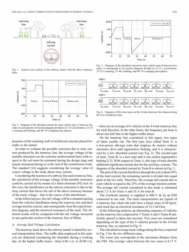
Fig. 17. Zoom of the equipotential surfaces, current field for segment 5-4 inposition B with a track voltage equal to 8 V and without the equipotential con-nection.
Fig. 18. Equipotential surfaces, current field inside soil, and reinforcement barsin position A with a track voltage equal to 8 V and with the equipotential con-nection.
A and without the equipotential connection are reported inFigs. 15–17.In particular, these figures show the effect of the electrical in-
sulation provided by the concrete and the contact resistance be-tween the segments themselves on the current conduction. Thecurrent leaves the upper segment, flows into the ground, andthen returns within the adjacent segment. This phenomenon de-pends on the placement of the segments in the tunnel ring. If thecontact surface between two adjacent segments is almost par-allel to the conduction field (i.e., segments 1-6), this phenom-enon is negligible. Vice-versa, it is noticeable when the contactsurface is almost perpendicular to the conduction field, such asbetween segments 5-6 and 5-4.As shown in [13], the different displacement of the segment
rings does not substantially change the phenomenon but only thenumerical values vary. Fig. 17 shows the worst case consideringthe segment ring in position B.The introduction of the equipotential connection brings about
the two global situations represented in Figs. 18 and 19 for theposition A and B, respectively.
Fig. 19. Equipotential surfaces, current field inside soil, and reinforcement barsin position B with a track voltage equal to 8 V and with the equipotential con-nection.
Fig. 20. Zoom of the equipotential surfaces, current field inside soil, and rein-forcement bars for segment 5-6 in position A with a track voltage equal to 8 Vand with the equipotential connection.
Fig. 21. Zoom of the equipotential surfaces, current field inside soil, and rein-forcement bars for segment 1-6 in position A with a track voltage equal to 8 Vand with the equipotential connection.
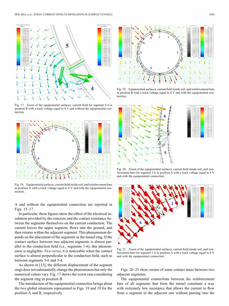
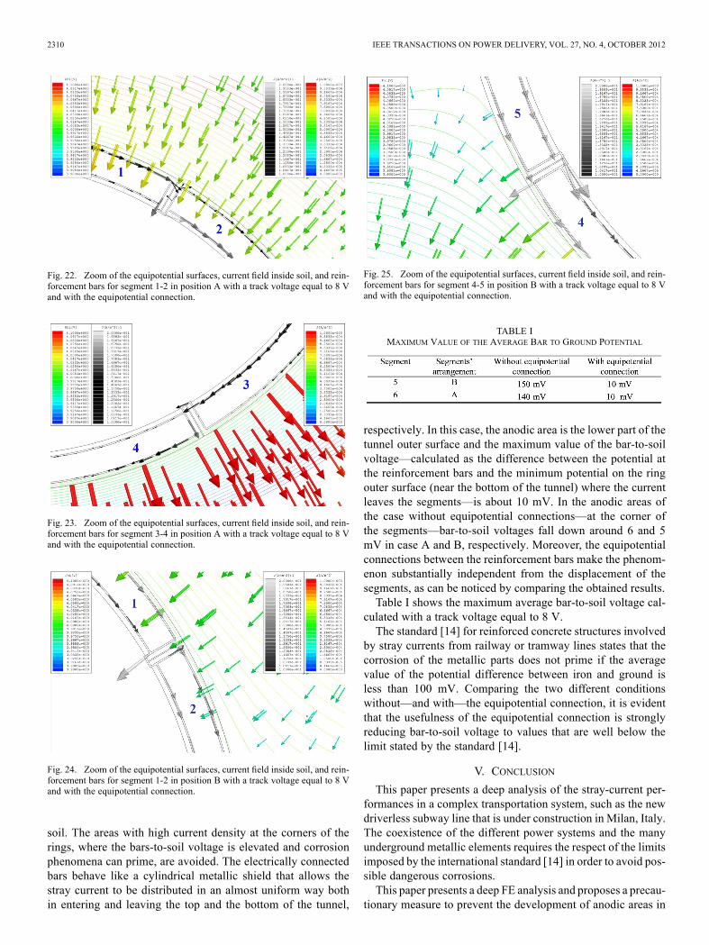
Figs. 20–25 show zooms of some contact areas between twoadjacent segments.The equipotential connections between the reinforcement
bars of all segments that form the tunnel constitute a waywith extremely low resistance that allows the current to flowfrom a segment to the adjacent one without passing into the
2310 IEEE TRANSACTIONS ON POWER DELIVERY, VOL. 27, NO. 4, OCTOBER 2012
Fig. 22. Zoom of the equipotential surfaces, current field inside soil, and rein-forcement bars for segment 1-2 in position A with a track voltage equal to 8 Vand with the equipotential connection.
Fig. 23. Zoom of the equipotential surfaces, current field inside soil, and rein-forcement bars for segment 3-4 in position A with a track voltage equal to 8 Vand with the equipotential connection.
Fig. 24. Zoom of the equipotential surfaces, current field inside soil, and rein-forcement bars for segment 1-2 in position B with a track voltage equal to 8 Vand with the equipotential connection.
soil. The areas with high current density at the corners of therings, where the bars-to-soil voltage is elevated and corrosionphenomena can prime, are avoided. The electrically connectedbars behave like a cylindrical metallic shield that allows thestray current to be distributed in an almost uniform way bothin entering and leaving the top and the bottom of the tunnel,
Fig. 25. Zoom of the equipotential surfaces, current field inside soil, and rein-forcement bars for segment 4-5 in position B with a track voltage equal to 8 Vand with the equipotential connection.
TABLE IMAXIMUM VALUE OF THE AVERAGE BAR TO GROUND POTENTIAL
respectively. In this case, the anodic area is the lower part of thetunnel outer surface and the maximum value of the bar-to-soilvoltage—calculated as the difference between the potential atthe reinforcement bars and the minimum potential on the ringouter surface (near the bottom of the tunnel) where the currentleaves the segments—is about 10 mV. In the anodic areas ofthe case without equipotential connections—at the corner ofthe segments—bar-to-soil voltages fall down around 6 and 5mV in case A and B, respectively. Moreover, the equipotentialconnections between the reinforcement bars make the phenom-enon substantially independent from the displacement of thesegments, as can be noticed by comparing the obtained results.Table I shows the maximum average bar-to-soil voltage cal-
culated with a track voltage equal to 8 V.The standard [14] for reinforced concrete structures involved
by stray currents from railway or tramway lines states that thecorrosion of the metallic parts does not prime if the averagevalue of the potential difference between iron and ground isless than 100 mV. Comparing the two different conditionswithout—and with—the equipotential connection, it is evidentthat the usefulness of the equipotential connection is stronglyreducing bar-to-soil voltage to values that are well below thelimit stated by the standard [14].
V. CONCLUSION
This paper presents a deep analysis of the stray-current per-formances in a complex transportation system, such as the newdriverless subway line that is under construction in Milan, Italy.The coexistence of the different power systems and the manyunderground metallic elements requires the respect of the limitsimposed by the international standard [14] in order to avoid pos-sible dangerous corrosions.This paper presents a deep FE analysis and proposes a precau-
tionary measure to prevent the development of anodic areas in
DOLARA et al.: STRAY CURRENT EFFECTS MITIGATION IN SUBWAY TUNNELS 2311
reinforcement bars, influencing the design procedure for betterenvironmental compatibility. In fact, the results obtained in thepreliminary study reported in [13] showed that the average po-tential of the reinforcement bars of tunnel segment rings dueto the tramway return currents could exceed the limits, causingpossible corrosion effects due to stray current.This paper starts from the model presented in [13] and, first
of all, validates the data implemented in the model through aninfield rail voltage measurement survey.Following this, it considers a possible improved solution
in order to avoid the zones with high-output current density.Therefore, the introduction of an equipotential connectionbetween the reinforcement bars of the adjacent segments hasbeen proposed. The simulation results demonstrate that thisprecautionary measure leads to a complete respect of thestandard limits and it can be considered as a solution to beintroduced in the transit system design in order to preventcorrosion phenomena once the system has been constructed.
REFERENCES[1] L. Chien-Hsing and L. Chien-Jung, “Assessment of grounding schemes
on rail potential and stray currents in a DC transit system,” IEEE Trans.Power Del., vol. 21, no. 4, pp. 1941–1947, Oct. 2006.
[2] I. Cotton, C. Charalambous, P. Aylott, and P. Ernst, “Stray current con-trol in DC mass transit systems,” IEEE Trans. Veh. Technol., vol. 54,no. 2, pp. 722–730, Mar. 2005.
[3] M. Niasati and A. Gholami, “Overview of stray current control in DCrailway systems,” in Proc. Int. Conf. Railway Eng.—Challenges forRailway Transport. Inf. Age, Mar. 25–28, 2008, pp. 1–6.
[4] S. Jamali, M. M. Alamuti, and M. Savaghebi, “Effects of differentearthing schemes on the stray current in rail transit systems,” in Proc.43rd Int. Univ. Power Eng. Conf., Sep. 1–4, 2008, pp. 1–5.
[5] Y. C. Liu and J. F. Chen, “Control scheme for reducing rail potentialand stray current in MRT systems,” in Proc. Inst. Elect. Eng., Elect.Power Appl., May 2005, vol. 152, no. 3, 6, pp. 612–618.
[6] M. Longhua and Zhouwei, “Stray current automatic monitoring systemand intelligent obviating, current device in metro,” in Proc. Int. PowerEng. Conf., Dec. 3–6, 2007, pp. 1070–1074.
[7] W. M. Sim and C. F. Chan, “Stray current monitoring and control onsingapore MRT system,” in Proc. Int. Conf. Power Syst. Technol., Nov.21–24, 2004, vol. 2, pp. 1898–1903.
[8] Jinmin and M. Longhua, “A novel on-line monitoring device of straycurrent in dc rail transit systems,” in Proc. Int. Conf. Power Syst.Technol., Oct. 22–26, 2006, pp. 1–4.
[9] J.-H. Bae, Y.-C. Ha, T.-H. Ha, H.-G. Lee, D.-K. Kim, and J.-D. Lee,“Data logger apparatus for stray current measurement of subway andpower line,” in Proc. 30th Annu. Conf. IEEE Ind. Electron. Soc., Nov.2–6, 2004, vol. 2, pp. 1563–1566.
[10] K. D. Pham, R. S. Thomas, and W. E. Stinger, “Analysis of stray cur-rent, track-to-earth potentials and substation negative grounding in DCtraction electrification system,” in Proc. IEEE/ASME Joint RailroadConf., Apr. 17–19, 2001, pp. 141–160.
[11] C.-H. Lee, “Evaluation of the maximum potential rise in taipei railtransit systems,” IEEE Trans. Power Del., vol. 20, no. 2, pt. 2, pp.1379–1384, Apr. 2005.
[12] S.-L. Chen, S.-C. Hsu, C.-T. Tseng, K.-H. Yan, H.-Y. Chou, and T.-M.Too, “Analysis of rail potential and stray current for taipei metro,”IEEE Trans. Veh. Technol., vol. 55, no. 1, pp. 67–75, Jan. 2006.
[13] M. Brenna, A. Dolara, S. Leva, and D. Zaninelli, “Effects of the DCstray currents on subway tunnel structures evaluated by FEM analysis,”inProc. IEEE Power Energy Soc. Gen. Meeting, Minneapolis,MN, Jul.25–29, 2010, p. 7.
[14] Railway Applications-Fixed Installations-Part 2: Protective Provi-sions Against The Effects of Stray Currents Caused By d.c. TractionSystems, Standard EN 50122-2, 1999.
[15] M. Brenna, F. Foiadelli, and D. Zaninelli, “New stability analysis fortuning PI controller of power converters in railway application,” IEEETrans. Ind. Electron., vol. 58, no. 2, pp. 533–543, Feb. 2011.
[16] T. Yii-Shen and L. Chien-Hsing, “Analysis of rail potential and straycurrents in a direct-current transit system,” IEEE Trans. Power Del.,vol. 25, no. 3, pp. 1516–1525, Jul. 2010.
[17] R. J. HiII, S. Brillante, and P. J. Leonard, “Railway track trans-mission line parameters from finite element field modeling—Seriesimpedance,” in Proc. Inst. Elect. Eng., Elect. Power Appl., Nov. 1999,vol. 146, no. 6.
[18] L. Bertolini, B. Elsener, R. Polder, and P. Pedeferri, Corrosion of Steelin Concrete—Prevention, Diagnosis, Repair. Hoboken, NJ: Wiley,Mar. 2004.
Alberto Dolara (S’09) received the M.S. andPh.D. degrees in electrical engineering from thePolitecnico di Milano, Milan, Italy, in 2005 and2010, respectively.Currently, is Temporary Researcher with the De-
partment of Energy, Politecnico di Milano, Milano,Italy. His areas of research include traction systems,power quality, electromagnetic compatibility, and re-newable sources.
Federica Foiadelli (M’08) received the M.Sc. andPh.D. degrees in electrical engineering from the Po-litecnico di Milano, Milan, Italy, in 2003 and 2008,respectively.Currently, she is Assistant Professor with the De-
partment of Energy, Politecnico di Milano. Her areasof research include electric power systems and elec-tric traction.Prof. Foiadelli is a member of CIFI (Italian Group
of Engineering about Railways and the Italian Elec-tric Association (AEI).
Sonia Leva (M’01) received the M.S. and Ph.D. de-grees in electrical engineering from the Politecnico diMilano, Milan, Italy, in 1997 and 2001, respectively.Currently, she is an Associate Professor of Elec-
trical Engineering with the Department of Energy,Politecnico di Milano. Her research interests includeelectromagnetic compatibility, power quality, thefoundation of the electromagnetic theory of theelectric network, and renewable energy.Prof. Leva is a member of the Italian Standard Au-
thority (CEI/CT82) and of the IEEE Working Group“Distributed Resources: Modeling & Analysis” and of the Task Force on “Mod-eling and Analysis of Electronically-Coupled Distributed Resources.”