Embed Size (px)
Citation preview

Stratix 5950 Security ApplianceCatalog Numbers 1783-SAD4T0SBK9, 1783-SAD4T0SPK9, 1783-SAD2T2SBK9, 1783-SAD2T2SPK9
User ManualOriginal Instructions
Important User Information
Read this document and the documents listed in the additional resources section about installation, configuration, and operation of this equipment before you install, configure, operate, or maintain this product. Users are required to familiarize themselves with installation and wiring instructions in addition to requirements of all applicable codes, laws, and standards.
Activities including installation, adjustments, putting into service, use, assembly, disassembly, and maintenance are required to be carried out by suitably trained personnel in accordance with applicable code of practice.
If this equipment is used in a manner not specified by the manufacturer, the protection provided by the equipment may be impaired.
In no event will Rockwell Automation, Inc. be responsible or liable for indirect or consequential damages resulting from the use or application of this equipment.
The examples and diagrams in this manual are included solely for illustrative purposes. Because of the many variables and requirements associated with any particular installation, Rockwell Automation, Inc. cannot assume responsibility or liability for actual use based on the examples and diagrams.
No patent liability is assumed by Rockwell Automation, Inc. with respect to use of information, circuits, equipment, or software described in this manual.
Reproduction of the contents of this manual, in whole or in part, without written permission of Rockwell Automation, Inc., is prohibited
Throughout this manual, when necessary, we use notes to make you aware of safety considerations.
Labels may also be on or inside the equipment to provide specific precautions.
WARNING: Identifies information about practices or circumstances that can cause an explosion in a hazardous environment, which may lead to personal injury or death, property damage, or economic loss.
ATTENTION: Identifies information about practices or circumstances that can lead to personal injury or death, property damage, or economic loss. Attentions help you identify a hazard, avoid a hazard, and recognize the consequence.
IMPORTANT Identifies information that is critical for successful application and understanding of the product.
SHOCK HAZARD: Labels may be on or inside the equipment, for example, a drive or motor, to alert people that dangerous voltage may be present.
BURN HAZARD: Labels may be on or inside the equipment, for example, a drive or motor, to alert people that surfaces may reach dangerous temperatures.
ARC FLASH HAZARD: Labels may be on or inside the equipment, for example, a motor control center, to alert people to potential Arc Flash. Arc Flash will cause severe injury or death. Wear proper Personal Protective Equipment (PPE). Follow ALL Regulatory requirements for safe work practices and for Personal Protective Equipment (PPE).
Table of Contents
Preface . . . . . . . . . . . . . . . . . . . . . . . . . . . . . . . . . . . . . . . . . . . . . . . . . . . . . . . .7Additional Resources . . . . . . . . . . . . . . . . . . . . . . . . . . . . . . . . . . . . . . . . . . . 8
Chapter 1About the Security Appliance Overview . . . . . . . . . . . . . . . . . . . . . . . . . . . . . . . . . . . . . . . . . . . . . . . . . . . . . . 9
Hardware Features . . . . . . . . . . . . . . . . . . . . . . . . . . . . . . . . . . . . . . . . . . . . 10Status Indicators. . . . . . . . . . . . . . . . . . . . . . . . . . . . . . . . . . . . . . . . . . . 13
Installation of the Security Appliance . . . . . . . . . . . . . . . . . . . . . . . . . . . 14Express Setup Button . . . . . . . . . . . . . . . . . . . . . . . . . . . . . . . . . . . . . . . . . . 14Power Supply . . . . . . . . . . . . . . . . . . . . . . . . . . . . . . . . . . . . . . . . . . . . . . . . . 15Small Form-Factor Pluggable (SFP) Modules . . . . . . . . . . . . . . . . . . . . 15Memory and Storage . . . . . . . . . . . . . . . . . . . . . . . . . . . . . . . . . . . . . . . . . . 15SD Card. . . . . . . . . . . . . . . . . . . . . . . . . . . . . . . . . . . . . . . . . . . . . . . . . . . . . . 15USB Ports . . . . . . . . . . . . . . . . . . . . . . . . . . . . . . . . . . . . . . . . . . . . . . . . . . . . 15Management Ethernet Port . . . . . . . . . . . . . . . . . . . . . . . . . . . . . . . . . . . . 16Console Port. . . . . . . . . . . . . . . . . . . . . . . . . . . . . . . . . . . . . . . . . . . . . . . . . . 16Alarm Ports. . . . . . . . . . . . . . . . . . . . . . . . . . . . . . . . . . . . . . . . . . . . . . . . . . . 17Power Supply . . . . . . . . . . . . . . . . . . . . . . . . . . . . . . . . . . . . . . . . . . . . . . . . . 17
CLI Commands . . . . . . . . . . . . . . . . . . . . . . . . . . . . . . . . . . . . . . . . . . . 17Temperature Sensor . . . . . . . . . . . . . . . . . . . . . . . . . . . . . . . . . . . . . . . . . . . 18Software Features . . . . . . . . . . . . . . . . . . . . . . . . . . . . . . . . . . . . . . . . . . . . . 18
Chapter 2Industrial Firewall Use Cases Industrial Firewall Technology Overview. . . . . . . . . . . . . . . . . . . . . . . . 19
Logical Framework . . . . . . . . . . . . . . . . . . . . . . . . . . . . . . . . . . . . . . . . . . . . 21Network Protection (Adaptive Security Appliance) . . . . . . . . . . . . . . 21Intrusion Prevention and Detection (FirePOWER). . . . . . . . . . . . . . 23Machine/Skid Protection . . . . . . . . . . . . . . . . . . . . . . . . . . . . . . . . . . . . . . 23
Transparent Mode. . . . . . . . . . . . . . . . . . . . . . . . . . . . . . . . . . . . . . . . . 23Routed Mode . . . . . . . . . . . . . . . . . . . . . . . . . . . . . . . . . . . . . . . . . . . . . . . . . 24
NAT . . . . . . . . . . . . . . . . . . . . . . . . . . . . . . . . . . . . . . . . . . . . . . . . . . . . . 24Considerations . . . . . . . . . . . . . . . . . . . . . . . . . . . . . . . . . . . . . . . . . . . . 25
Redundant Star Cell/Area Zone Protection . . . . . . . . . . . . . . . . . . . . . 26Considerations . . . . . . . . . . . . . . . . . . . . . . . . . . . . . . . . . . . . . . . . . . . . 26
Ring Cell/Area Zone Protection. . . . . . . . . . . . . . . . . . . . . . . . . . . . . . . . 27Considerations . . . . . . . . . . . . . . . . . . . . . . . . . . . . . . . . . . . . . . . . . . . . 28
Cell/Area Zone Monitoring. . . . . . . . . . . . . . . . . . . . . . . . . . . . . . . . . . . . 29Considerations . . . . . . . . . . . . . . . . . . . . . . . . . . . . . . . . . . . . . . . . . . . . 29
Time Synchronization . . . . . . . . . . . . . . . . . . . . . . . . . . . . . . . . . . . . . . . . . 30
Rockwell Automation Publication 1783-UM010B-EN-P - March 2018 3
Table of Contents
Chapter 3Configure the Security Appliance Prerequisites . . . . . . . . . . . . . . . . . . . . . . . . . . . . . . . . . . . . . . . . . . . . . . . . . . 38
Ethernet Devices . . . . . . . . . . . . . . . . . . . . . . . . . . . . . . . . . . . . . . . . . . . . . . 38Device Setup. . . . . . . . . . . . . . . . . . . . . . . . . . . . . . . . . . . . . . . . . . . . . . . . . . 39
Startup Wizard. . . . . . . . . . . . . . . . . . . . . . . . . . . . . . . . . . . . . . . . . . . . 41Configure FirePOWER Administrative Settings . . . . . . . . . . . . . 49Configure the HTTPS Certificate Information . . . . . . . . . . . . . . 51
Configure a Test Policy to Block CIP Administrative Traffic . . . . . 53Add a Rule . . . . . . . . . . . . . . . . . . . . . . . . . . . . . . . . . . . . . . . . . . . . . . . . 60Update Real Time Eventing View . . . . . . . . . . . . . . . . . . . . . . . . . . . 63Change the Device from Monitor Mode to a Full Blocking Configuration (Inline Mode Only). . . . . . . . . . . . . . . . . . . . . . . . . . 65Configure SPAN Port monitoring settings. . . . . . . . . . . . . . . . . . . 67Change the IP Address of the Communication Module. . . . . . . 68
Chapter 4Monitor the Security Appliance Status Indicators . . . . . . . . . . . . . . . . . . . . . . . . . . . . . . . . . . . . . . . . . . . . . . 71
Chapter 5Centralized Management Overview . . . . . . . . . . . . . . . . . . . . . . . . . . . . . . . . . . . . . . . . . . . . . . . . . . . . . 73
FireSIGHT Management Center . . . . . . . . . . . . . . . . . . . . . . . . . . . . . . . 73Cisco Security Manager (CSM) . . . . . . . . . . . . . . . . . . . . . . . . . . . . . . . . 75Management Recommendations. . . . . . . . . . . . . . . . . . . . . . . . . . . . . . . . 77Integration of New Firewalls . . . . . . . . . . . . . . . . . . . . . . . . . . . . . . . . . . . 77Centralized Management . . . . . . . . . . . . . . . . . . . . . . . . . . . . . . . . . . . . . . 78
Chapter 6Hardware Bypass Power Failure of the System . . . . . . . . . . . . . . . . . . . . . . . . . . . . . . . . . . . . 79
Enable the Hardware Bypass by Using CLI Commands . . . . . . . . . . 79Default State of the Hardware Bypass . . . . . . . . . . . . . . . . . . . . . . . 80
ASA CLI Commands for Hardware Bypass . . . . . . . . . . . . . . . . . . . . . 80Limitations of Hardware Bypass . . . . . . . . . . . . . . . . . . . . . . . . . . . . . . . . 81
Hardware Bypass CLI. . . . . . . . . . . . . . . . . . . . . . . . . . . . . . . . . . . . . . 81
Chapter 7CIP Inspection CIP Preprocessor. . . . . . . . . . . . . . . . . . . . . . . . . . . . . . . . . . . . . . . . . . . . . . 85
CIP Access Control Policies . . . . . . . . . . . . . . . . . . . . . . . . . . . . . . . . 86CIP Access Control Policy Rule Limitations . . . . . . . . . . . . . . . . . 87CIP Intrusion Policies . . . . . . . . . . . . . . . . . . . . . . . . . . . . . . . . . . . . . 87
4 Rockwell Automation Publication 1783-UM010B-EN-P - March 2018
Table of Contents
Chapter 8Firewall Modes Industrial Firewall Deployment Considerations. . . . . . . . . . . . . . . . . . 90
Inline Transparent Mode . . . . . . . . . . . . . . . . . . . . . . . . . . . . . . . . . . 90Inline Transparent Monitor-only Mode . . . . . . . . . . . . . . . . . . . . . 92
Inline Routed Mode . . . . . . . . . . . . . . . . . . . . . . . . . . . . . . . . . . . . . . . . . . . 93Passive Monitor-only Mode . . . . . . . . . . . . . . . . . . . . . . . . . . . . . . . . . . . . 93Deployment Recommendations . . . . . . . . . . . . . . . . . . . . . . . . . . . . . . . . 94Industrial Firewall Use Cases . . . . . . . . . . . . . . . . . . . . . . . . . . . . . . . . . . . 95
Machine/Skid Protection . . . . . . . . . . . . . . . . . . . . . . . . . . . . . . . . . . 95Redundant Star Cell/Area Zone Protection. . . . . . . . . . . . . . . . . . 97Ring Cell/Area Zone Protection . . . . . . . . . . . . . . . . . . . . . . . . . . . . 99Cell/Area Zone Monitoring . . . . . . . . . . . . . . . . . . . . . . . . . . . . . . . 100
Chapter 9Troubleshoot Obtain the Current Running Software Versions . . . . . . . . . . . . . . . . 101
Updating ASA/ASDM software. . . . . . . . . . . . . . . . . . . . . . . . . . . . . . . 102(ASDM) Upgrade from Your Local Computer. . . . . . . . . . . . . . 102
Reset the Device to Factory Defaults . . . . . . . . . . . . . . . . . . . . . . . . . . . 103Uninstall an Old SFR Module . . . . . . . . . . . . . . . . . . . . . . . . . . . . . 104Reinstall an SFR Module . . . . . . . . . . . . . . . . . . . . . . . . . . . . . . . . . . 105Install the SFR 5.4.1.2 Update . . . . . . . . . . . . . . . . . . . . . . . . . . . . . 107Install the SFR 5.4.1.4 Update . . . . . . . . . . . . . . . . . . . . . . . . . . . . . 108Install SFR 5.4.1.6 Update . . . . . . . . . . . . . . . . . . . . . . . . . . . . . . . . 108Install the SFR License . . . . . . . . . . . . . . . . . . . . . . . . . . . . . . . . . . . . 108Final Reset . . . . . . . . . . . . . . . . . . . . . . . . . . . . . . . . . . . . . . . . . . . . . . . 109
Glossary . . . . . . . . . . . . . . . . . . . . . . . . . . . . . . . . . . . . . . . . . . . . . . . . . . . . 111
Index . . . . . . . . . . . . . . . . . . . . . . . . . . . . . . . . . . . . . . . . . . . . . . . . . . . . . . 113
Rockwell Automation Publication 1783-UM010B-EN-P - March 2018 5

Table of Contents
Notes:
6 Rockwell Automation Publication 1783-UM010B-EN-P - March 2018
Preface
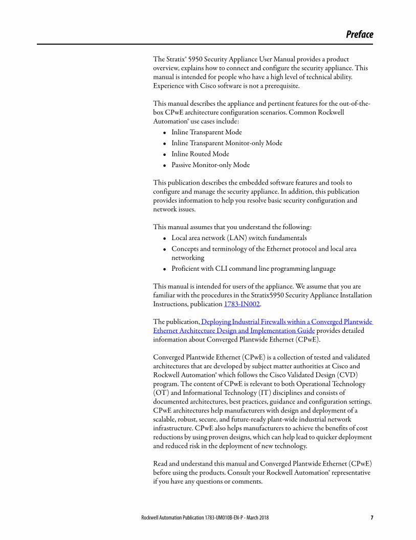
The Stratix® 5950 Security Appliance User Manual provides a product overview, explains how to connect and configure the security appliance. This manual is intended for people who have a high level of technical ability. Experience with Cisco software is not a prerequisite.
This manual describes the appliance and pertinent features for the out-of-the-box CPwE architecture configuration scenarios. Common Rockwell Automation® use cases include:
• Inline Transparent Mode• Inline Transparent Monitor-only Mode• Inline Routed Mode• Passive Monitor-only Mode
This publication describes the embedded software features and tools to configure and manage the security appliance. In addition, this publication provides information to help you resolve basic security configuration and network issues.
This manual assumes that you understand the following:• Local area network (LAN) switch fundamentals• Concepts and terminology of the Ethernet protocol and local area
networking• Proficient with CLI command line programming language
This manual is intended for users of the appliance. We assume that you are familiar with the procedures in the Stratix5950 Security Appliance Installation Instructions, publication 1783-IN002.
The publication, Deploying Industrial Firewalls within a Converged Plantwide Ethernet Architecture Design and Implementation Guide provides detailed information about Converged Plantwide Ethernet (CPwE).
Converged Plantwide Ethernet (CPwE) is a collection of tested and validated architectures that are developed by subject matter authorities at Cisco and Rockwell Automation® which follows the Cisco Validated Design (CVD) program. The content of CPwE is relevant to both Operational Technology (OT) and Informational Technology (IT) disciplines and consists of documented architectures, best practices, guidance and configuration settings. CPwE architectures help manufacturers with design and deployment of a scalable, robust, secure, and future-ready plant-wide industrial network infrastructure. CPwE also helps manufacturers to achieve the benefits of cost reductions by using proven designs, which can help lead to quicker deployment and reduced risk in the deployment of new technology.
Read and understand this manual and Converged Plantwide Ethernet (CPwE) before using the products. Consult your Rockwell Automation® representative if you have any questions or comments.
Rockwell Automation Publication 1783-UM010B-EN-P - March 2018 7
Preface
Download firmware, associated files, and access product release notes from the Product Compatibility and Download Center at:http://www.rockwellautomation.com/rockwellautomation/support/pcdc.page
The Cisco Firewall and Firepower manuals provide detailed instructions, including these topics:
• Cisco ASA software and hardware compatibility and requirements• Cisco ASA series documentation• Cisco Security Manager • FirePOWER System, Cisco SSL Appliance, and FireAMP
Links to these manuals are available in Additional Resources on page 8.
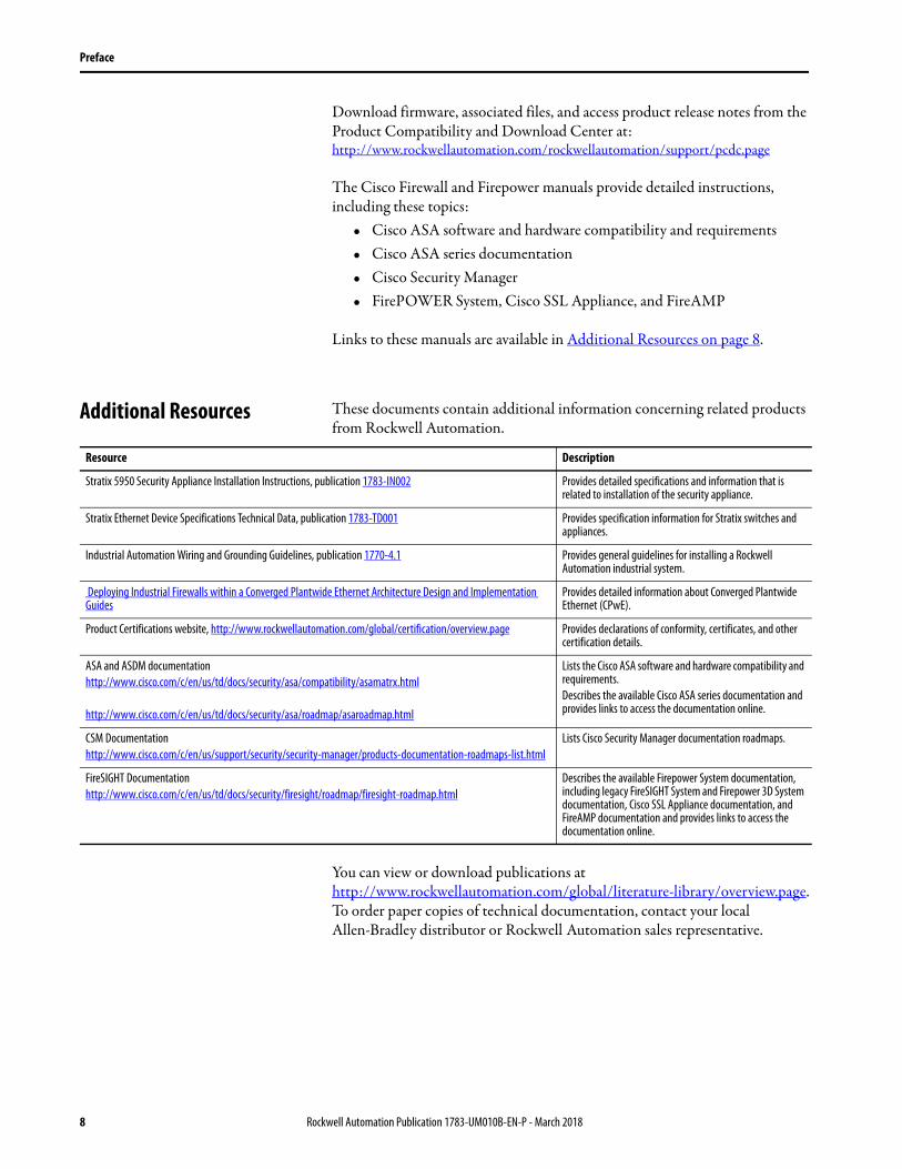
Additional Resources These documents contain additional information concerning related products from Rockwell Automation.
You can view or download publications athttp://www.rockwellautomation.com/global/literature-library/overview.page. To order paper copies of technical documentation, contact your local Allen-Bradley distributor or Rockwell Automation sales representative.
Resource Description
Stratix 5950 Security Appliance Installation Instructions, publication 1783-IN002 Provides detailed specifications and information that is related to installation of the security appliance.
Stratix Ethernet Device Specifications Technical Data, publication 1783-TD001 Provides specification information for Stratix switches and appliances.
Industrial Automation Wiring and Grounding Guidelines, publication 1770-4.1 Provides general guidelines for installing a Rockwell Automation industrial system.
Deploying Industrial Firewalls within a Converged Plantwide Ethernet Architecture Design and Implementation Guides
Provides detailed information about Converged Plantwide Ethernet (CPwE).
Product Certifications website, http://www.rockwellautomation.com/global/certification/overview.page Provides declarations of conformity, certificates, and other certification details.
ASA and ASDM documentationhttp://www.cisco.com/c/en/us/td/docs/security/asa/compatibility/asamatrx.html
http://www.cisco.com/c/en/us/td/docs/security/asa/roadmap/asaroadmap.html
Lists the Cisco ASA software and hardware compatibility and requirements.Describes the available Cisco ASA series documentation and provides links to access the documentation online.
CSM Documentationhttp://www.cisco.com/c/en/us/support/security/security-manager/products-documentation-roadmaps-list.html
Lists Cisco Security Manager documentation roadmaps.
FireSIGHT Documentationhttp://www.cisco.com/c/en/us/td/docs/security/firesight/roadmap/firesight-roadmap.html
Describes the available Firepower System documentation, including legacy FireSIGHT System and Firepower 3D System documentation, Cisco SSL Appliance documentation, and FireAMP documentation and provides links to access the documentation online.
8 Rockwell Automation Publication 1783-UM010B-EN-P - March 2018
Chapter 1
About the Security Appliance
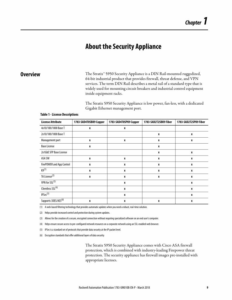
Overview The Stratix™ 5950 Security Appliance is a DIN Rail-mounted ruggedized, 64-bit industrial product that provides firewall, threat defense, and VPN services. The term DIN Rail describes a metal rail of a standard type that is widely used for mounting circuit breakers and industrial control equipment inside equipment racks.
The Stratix 5950 Security Appliance is low power, fan-less, with a dedicated Gigabit Ethernet management port.
The Stratix 5950 Security Appliance comes with Cisco ASA firewall protection, which is combined with industry-leading Firepower threat protection. The security appliance has firewall images pre-installed with appropriate licenses.
Table 1 - License Descriptions
License Attribute 1783-SAD4T0SBK9 Copper 1783-SAD4T0SPK9 Copper 1783-SAD2T2SBK9 Fiber 1783-SAD2T2SPK9 Fiber
4x10/100/1000 Base T x x
2x10/100/1000 Base T x x
Management port x x x x
Base License x x
2x1GbE SFP Base License x x
ASA SW x x x x
FirePOWER and App Control x x x x
K9(1) x x x x
TA License(2) x x x x
VPN for SSL(3) x x
Clientless SSL(4) x x
IPSec(5) x x
Supports 3DES/AES(6) x x x x
(1) A web-based filtering technology that provides automatic updates when you need a robust, real-time solution.
(2) Helps provide increased control and protection during system updates.
(3) Allows for the creation of a secure, encrypted connection without requiring specialized software on an end user’s computer.
(4) Helps ensure secure access to pre-configured network resources on a corporate network using an SSL-enabled web browser.
(5) IPSec is a standard set of protocols that provide data security at the IP packet level.
(6) Encryption standards that offer additional layers of data security
Rockwell Automation Publication 1783-UM010B-EN-P - March 2018 9

Chapter 1 About the Security Appliance
Hardware Features The following are the hardware features Stratix 5950 Security Appliance.• Dedicated management-only Gigabit Ethernet port• Mini-USB and RJ45 Console port• Bypass Relay (only available on copper ports). Bypass relay is used when
there is a loss of power or under software control• +/- 12V DC to 48V DC Rated (9.6V DC to 60V DC Maximum)
redundant power inputs with 20-12 AWG screw cage terminals • Cisco ASA firewall protection, which is combined with industry-
leading Firepower threat protection• Two external USB-A ports for addition of memory cards, security
tokens, modems, or other USB 2.0 compliant devices• Two alarm inputs• Fault relay outputs • DIN Rail mounts incorporated into the chassis• Fan-less design• Industrial temperature SDHC card • Secure boot support
For complete information on how to install the security appliance, see the Stratix 5950 Security Appliance Installation Instructions, publication 1783-IN002.
10 Rockwell Automation Publication 1783-UM010B-EN-P - March 2018
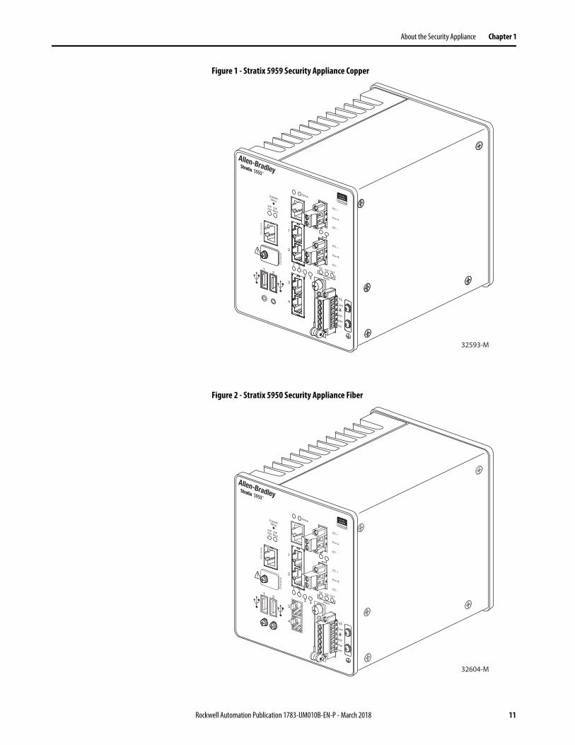
About the Security Appliance Chapter 1
Figure 1 - Stratix 5959 Security Appliance Copper
Figure 2 - Stratix 5950 Security Appliance Fiber
32593-M
32604-M
Rockwell Automation Publication 1783-UM010B-EN-P - March 2018 11
Chapter 1 About the Security Appliance
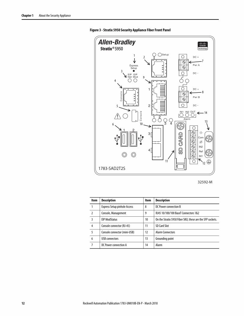
Figure 3 - Stratix 5950 Security Appliance Fiber Front Panel
Item Description Item Description
1 Express Setup pinhole Access 8 DC Power connection B
2 Console, Management 9 RJ45 10/100/100 BaseT Connectors 1&2
3 EIP ModStatus 10 On the Stratix 5950 Fiber SKU, these are the SFP sockets.
4 Console connector (RJ-45) 11 SD Card Slot
5 Console connector (mini-USB) 12 Alarm Connectors
6 USB connectors 13 Grounding point
7 DC Power connection A 14 Alarm
32592-M
1783-SAD2T2S
®1
7
9
6
4
3
8
14
13
1211
10
5
2
12 Rockwell Automation Publication 1783-UM010B-EN-P - March 2018
About the Security Appliance Chapter 1
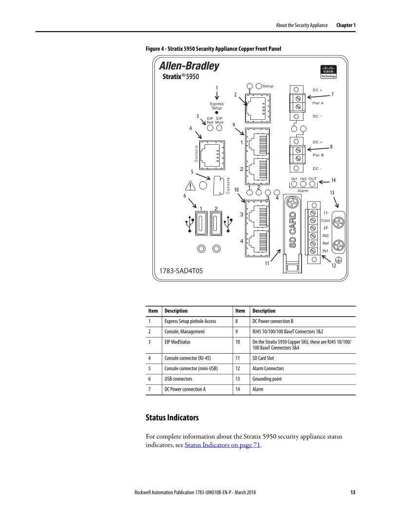
Figure 4 - Stratix 5950 Security Appliance Copper Front Panel
Status Indicators
For complete information about the Stratix 5950 security appliance status indicators, see Status Indicators on page 71.
Item Description Item Description
1 Express Setup pinhole Access 8 DC Power connection B
2 Console, Management 9 RJ45 10/100/100 BaseT Connectors 1&2
3 EIP ModStatus 10 On the Stratix 5950 Copper SKU, these are RJ45 10/100/100 BaseT Connectors 3&4
4 Console connector (RJ-45) 11 SD Card Slot
5 Console connector (mini-USB) 12 Alarm Connectors
6 USB connectors 13 Grounding point
7 DC Power connection A 14 Alarm
1783-SAD4T0S
®1
7
9
6
4
3
8
14
13
1211
10
5
2
Rockwell Automation Publication 1783-UM010B-EN-P - March 2018 13
Chapter 1 About the Security Appliance
Installation of the Security Appliance
To install the Stratix 5950 Security Appliance, follow the introductions in the Stratix 5950 Security Appliance Installation Instructions, publication 1783-IN002.
Express Setup Button The Express Setup button resets the security appliance ASA configuration to the default configuration set by the factory.
To restore the security appliance configuration to the default configuration set by the factory, follow these steps.
1. Use a standard size #1 paper clip with wire gauge 0.033 inches or smaller and
2. Press the Express Setup button after the device is fully booted.
When depressed the push button follows these actions:• Depressed 0 to < 3 seconds or > 15 seconds — No action is taken.• Depressed > 3 seconds < 15 seconds —
The appliance automatically restarts when the button is pushed. After restart, the unit runs the original factory default configuration.
The FirePOWER module is NOT reset to Factory Default with the Express Setup button pressed for >3 seconds and < 15 seconds.
TIP The new configuration does not take effect until after the system restarts. The system boots with the original factory default configuration, including ROMMON variables. The administrator can disable this feature via ASA CLI so that no action is taken when the push button is depressed.
14 Rockwell Automation Publication 1783-UM010B-EN-P - March 2018
About the Security Appliance Chapter 1
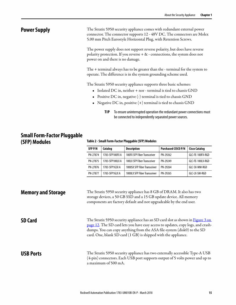
Power Supply The Stratix 5950 security appliance comes with redundant external power connector. The connector supports 12 - 48V DC. The connectors are Molex 5.00 mm Pitch Eurostyle Horizontal Plug, with Retention Screws.
The power supply does not support reverse polarity, but does have reverse polarity protection. If you reverse + & - connections, the system does not power on and there is no damage.
The + terminal always has to be greater than the - terminal for the system to operate. The difference is in the system grounding scheme used.
The Stratix 5950 security appliance supports three basic schemes:• Isolated DC in, neither + nor - terminal is tied to chassis GND• Positive DC in, negative (-) terminal is tied to chassis GND• Negative DC in, positive (+) terminal is tied to chassis GND
Small Form-Factor Pluggable (SFP) Modules
Memory and Storage The Stratix 5950 security appliance has 8 GB of DRAM. It also has two storage devices, a 50 GB SSD and a 15 GB update device. All memory components are factory default and not upgradeable by the end user.
SD Card The Stratix 5950 security appliance has an SD card slot as shown in Figure 3 on page 12. The SD card lets you have easy access to updates, copy logs, and crash-dumps. You can copy anything from the ASA file-system (disk0) to the SD card. One, blank SD card (1 GB) is shipped with the appliance.
USB Ports The Stratix 5950 security appliance has two externally accessible Type-A USB (4-pin) connectors. Each USB port supports output of 5 volts power and up to a maximum of 500 mA.
TIP To ensure uninterrupted operation the redundant power connections must be connected to independently separated power sources.
Table 2 - Small Form-Factor Pluggable (SFP) Modules
SFP P/N Catalog Description Purchased CISCO P/N Cisco Catalog
PN-27874 1783-SFP100FX A 100FX SFP Fiber Transceiver PN-29262 GLC-FE-100FX-RGD
PN-27875 1783-SFP100LX A 100LX SFP Fiber Transceiver PN-29249 GLC-FE-100LX-RGD
PN-27876 1783-SFP1GSX A 1000SX SFP Fiber Transceiver PN-29264 GLC-SX-MM-RGD
PN-27877 1783-SFP1GLX A 1000LX SFP Fiber Transceiver PN-29265 GLC-LX-SM-RGD
Rockwell Automation Publication 1783-UM010B-EN-P - March 2018 15
Chapter 1 About the Security Appliance
Management Ethernet Port A management-only 10/100/1000 BaseT Ethernet port is provided. This port is the only port that is able to configure the device for initial setup of the system. This port is Management1/1 in the ASA configuration.
Console Port You can configure the Stratix 5950 security appliance through a web interface, or through the console port. The console port is either a RJ45 or a Mini USB connector. You can use the Rockwell Automation USB to RJ45 console cable (part number 9300-USBCBL-CNSL).
The default configuration settings for the RJ45 console port are:
9600 baud, 8 data bits, no parity, 1 stop bit, no flow control.
If the USB Console Port is active (cable that is inserted and remote personal computer drivers are enabled) by default the console switches from RJ45 to USB when the USB cable is detected. If both ports are connected, the Mini USB console port is used.
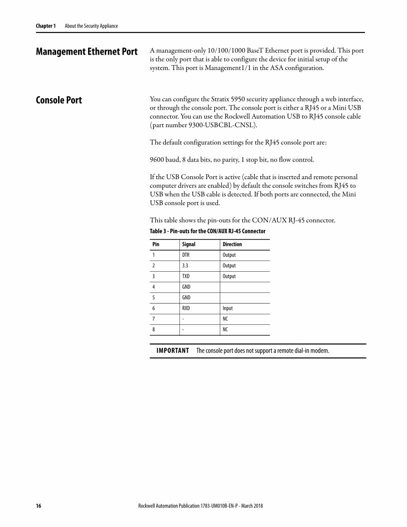
This table shows the pin-outs for the CON/AUX RJ-45 connector.Table 3 - Pin-outs for the CON/AUX RJ-45 Connector
Pin Signal Direction
1 DTR Output
2 3.3 Output
3 TXD Output
4 GND
5 GND
6 RXD Input
7 - NC
8 - NC
IMPORTANT The console port does not support a remote dial-in modem.
16 Rockwell Automation Publication 1783-UM010B-EN-P - March 2018
About the Security Appliance Chapter 1
Alarm Ports The Stratix 5950 security appliance has alarm ports as shown in Figure 1 on page 11. There are two conditions that can generate an alarm:
• When dual power supply is configured, and there is a failed or missing power supply.
• When the CPU temperature is in critical condition below -40 °C or above 105 °C (below -40 °F or above 221 °F)
When either condition is met, the alarm status indicator turns red, and a syslog message and SNMP trap is triggered.
The Stratix 5950 security appliance has alarm relay contacts that can be used for an external alert system. The alarm condition of a missing/failed power supply, when ‘power-supply dual’ is configured, triggers Alarm Relay output. This alarm condition also sets the alarm output status indicator to solid RED and sends out a syslog message.
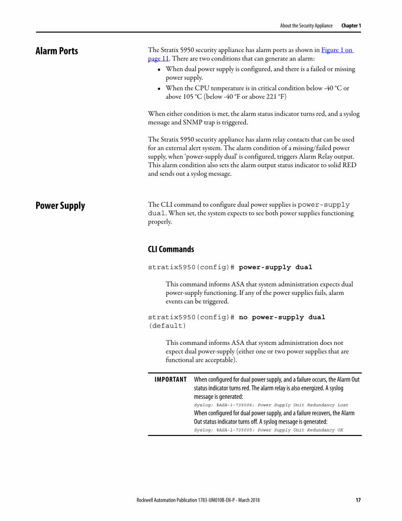
Power Supply The CLI command to configure dual power supplies is power-supply dual. When set, the system expects to see both power supplies functioning properly.
CLI Commands
stratix5950(config)# power-supply dual
This command informs ASA that system administration expects dual power-supply functioning. If any of the power supplies fails, alarm events can be triggered.
stratix5950(config)# no power-supply dual (default)
This command informs ASA that system administration does not expect dual power-supply (either one or two power supplies that are functional are acceptable).
IMPORTANT When configured for dual power supply, and a failure occurs, the Alarm Out status indicator turns red. The alarm relay is also energized. A syslog message is generated:Syslog: %ASA-1-735006: Power Supply Unit Redundancy Lost
When configured for dual power supply, and a failure recovers, the Alarm Out status indicator turns off. A syslog message is generated:Syslog: %ASA-1-735005: Power Supply Unit Redundancy OK
Rockwell Automation Publication 1783-UM010B-EN-P - March 2018 17
Chapter 1 About the Security Appliance
Temperature Sensor The operating system monitors the CPU temperature when it is running.• If the CPU temperature is in a critical condition, below -40 °C or above
+105 °C (below -40 °F or above +221 °F) the Alarm Out status indicator turns red.
• When the CPU temperature returns to a normal condition, the Alarm Out status indicator turns off.
The critical range of temperature is not configurable. It is hard-coded as below -40° C or above +105 °C (below -40 °F or above +221 °F).
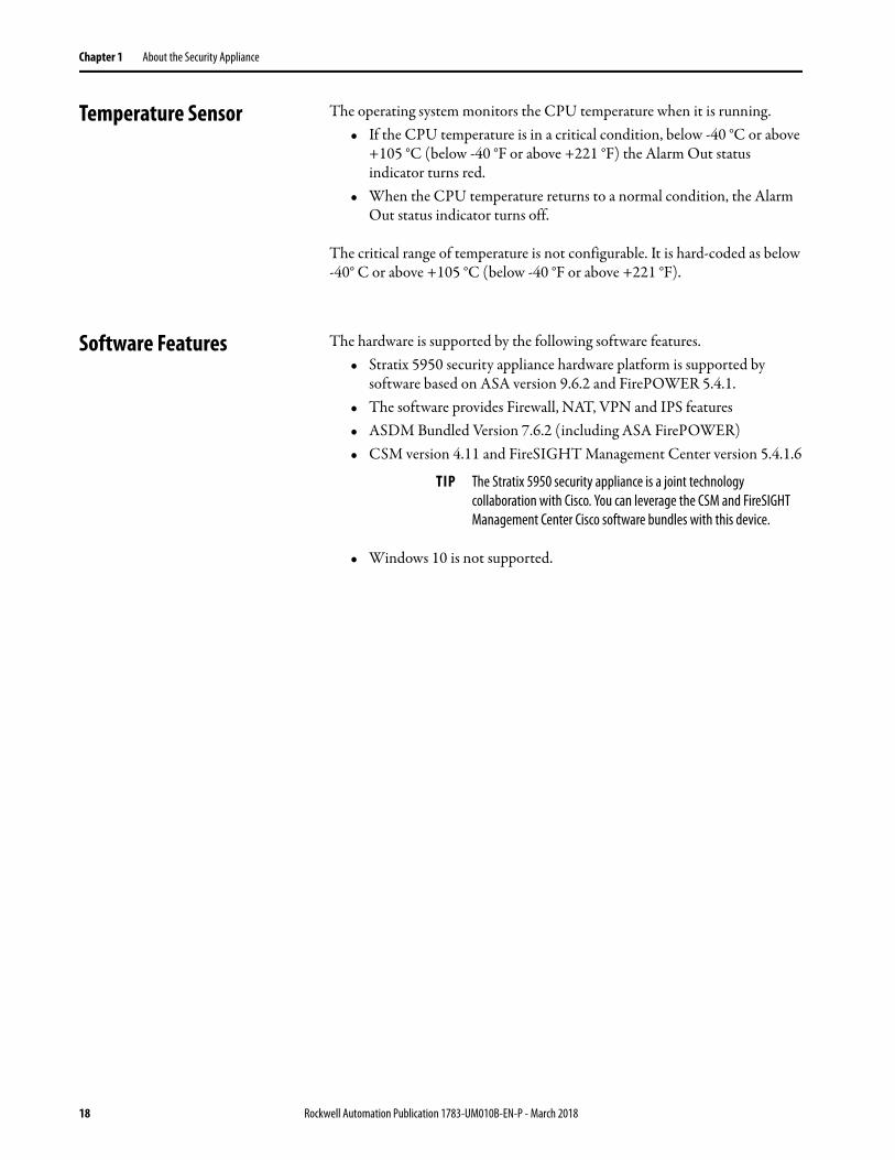
Software Features The hardware is supported by the following software features.• Stratix 5950 security appliance hardware platform is supported by
software based on ASA version 9.6.2 and FirePOWER 5.4.1.• The software provides Firewall, NAT, VPN and IPS features • ASDM Bundled Version 7.6.2 (including ASA FirePOWER)• CSM version 4.11 and FireSIGHT Management Center version 5.4.1.6
• Windows 10 is not supported.
TIP The Stratix 5950 security appliance is a joint technology collaboration with Cisco. You can leverage the CSM and FireSIGHT Management Center Cisco software bundles with this device.
18 Rockwell Automation Publication 1783-UM010B-EN-P - March 2018
Chapter 2
Industrial Firewall Use Cases
An IACS is deployed in a wide variety of discrete and process manufacturing industries such as automotive, pharmaceuticals, consumer goods, pulp and paper, oil and gas, mining and energy. IACS applications are made up of multiple control and information disciplines such as continuous process, batch, discrete and hybrid combinations. One of the challenges facing manufacturers is the industrial hardening of standard Ethernet and IP converged IACS networking technologies to take advantage of the business benefits associated with the Industrial Internet of Things (IIoT).
Industrial Firewall Technology Overview
The Industrial Firewall (IFW) is used to separate networks with differing security requirements and is also strategically placed within a network to monitor and log traffic. In this section, several architectures and the use cases they are meant to address are discussed.
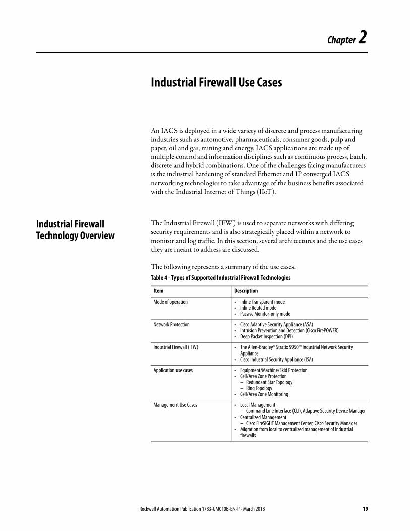
The following represents a summary of the use cases.Table 4 - Types of Supported Industrial Firewall Technologies
Item Description
Mode of operation • Inline Transparent mode• Inline Routed mode• Passive Monitor-only mode
Network Protection • Cisco Adaptive Security Appliance (ASA)• Intrusion Prevention and Detection (Cisco FirePOWER) • Deep Packet Inspection (DPI)
Industrial Firewall (IFW) • The Allen-Bradley® Stratix 5950™ Industrial Network Security Appliance
• Cisco Industrial Security Appliance (ISA)
Application use cases • Equipment/Machine/Skid Protection• Cell/Area Zone Protection
– Redundant Star Topology– Ring Topology
• Cell/Area Zone Monitoring
Management Use Cases • Local Management– Command Line Interface (CLI), Adaptive Security Device Manager
• Centralized Management – Cisco FireSIGHT Management Center, Cisco Security Manager
• Migration from local to centralized management of industrial firewalls
Rockwell Automation Publication 1783-UM010B-EN-P - March 2018 19

Chapter 2 Industrial Firewall Use Cases
Figure 5 - Plant-wide Industrial Firewall Deployments
20 Rockwell Automation Publication 1783-UM010B-EN-P - March 2018
Industrial Firewall Use Cases Chapter 2
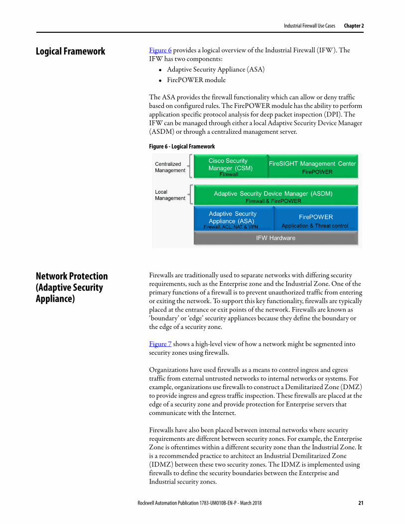
Logical Framework Figure 6 provides a logical overview of the Industrial Firewall (IFW). The IFW has two components:
• Adaptive Security Appliance (ASA)• FirePOWER module
The ASA provides the firewall functionality which can allow or deny traffic based on configured rules. The FirePOWER module has the ability to perform application specific protocol analysis for deep packet inspection (DPI). The IFW can be managed through either a local Adaptive Security Device Manager (ASDM) or through a centralized management server.
Figure 6 - Logical Framework
Network Protection (Adaptive Security Appliance)
Firewalls are traditionally used to separate networks with differing security requirements, such as the Enterprise zone and the Industrial Zone. One of the primary functions of a firewall is to prevent unauthorized traffic from entering or exiting the network. To support this key functionality, firewalls are typically placed at the entrance or exit points of the network. Firewalls are known as ‘boundary’ or ‘edge’ security appliances because they define the boundary or the edge of a security zone.
Figure 7 shows a high-level view of how a network might be segmented into security zones using firewalls.
Organizations have used firewalls as a means to control ingress and egress traffic from external untrusted networks to internal networks or systems. For example, organizations use firewalls to construct a Demilitarized Zone (DMZ) to provide ingress and egress traffic inspection. These firewalls are placed at the edge of a security zone and provide protection for Enterprise servers that communicate with the Internet.
Firewalls have also been placed between internal networks where security requirements are different between security zones. For example, the Enterprise Zone is oftentimes within a different security zone than the Industrial Zone. It is a recommended practice to architect an Industrial Demilitarized Zone (IDMZ) between these two security zones. The IDMZ is implemented using firewalls to define the security boundaries between the Enterprise and Industrial security zones.
Rockwell Automation Publication 1783-UM010B-EN-P - March 2018 21

Chapter 2 Industrial Firewall Use Cases
Figure 7 shows how the security zones depicted can be applied to the CPwE network architecture to create DMZs and other types of segmentation.
Figure 7 - Security Zones within CPwE Architecture
Firewalls are normally positioned either as a node where the network splits into multiple paths, or inline with a single network path. In routed networks, the firewall usually resides at the location immediately before traffic enters the router. The vast majority of firewalls are capable of providing routing and in some network designs, the firewall will act as both the firewall and the router.
Most firewalls are capable of inspecting the following elements of a packet:• Source MAC or IP Address• Destination MAC or IP Address• Source TCP or UDP Port • Destination TCP or UDP Port• Protocol - Layer 2, 3, 4, or 7
These are commonly known as five-tuple firewalls. Typically firewall rules will include these five elements to configure a rule. The firewall will be configured to permit or deny ingress and egress traffic based on these five-tuple rules.
A firewall may inspect traffic for conformance with proper protocol behavior and drop non-compliant traffic, but the firewall will not have deep knowledge of the protocol. In order to inspect and make permit and deny decisions at the protocol level, deep packet inspection (DPI) capabilities are needed, and these are discussed in the following section.
22 Rockwell Automation Publication 1783-UM010B-EN-P - March 2018
Industrial Firewall Use Cases Chapter 2
Intrusion Prevention and Detection (FirePOWER)
Deep packet inspection (DPI) provides the ability to inspect the packet past the basic header information at the protocol level. DPI determines the contents of a particular packet, and then either records that information for statistical purposes or performs an action on the packet such as permit or discard. DPI is a capability while Intrusion Detection and Intrusion Prevention use DPI technology. IPS and IDS relate to what is to be done after the packet has been inspected by DPI.
As mentioned in the previous section, the primary function of the firewall is to permit or deny traffic between networks based on configured rules. Some firewalls may inspect traffic for conformance with proper protocol behavior and drop non-compliant traffic but DPI functionality is required to interpret beyond the basic protocol behavior. Protocol interpretation is added to the DPI module so an administrator can configure DPI rules to monitor, log, permit or deny packets as they relate to the protocol.
Intrusion Prevention System (IPS) inspects traffic flowing through a network and is capable of blocking or otherwise remediating flows that it determines are malicious. Usually IPS devices are placed inline with the traffic so the traffic can be blocked before entering or exiting the network or before it reaches the end hosts.
Intrusion Detection System (IDS) are similar to IPS but does not affect flows in any way. IDS only logs or alerts on malicious traffic based on the DPI rules.
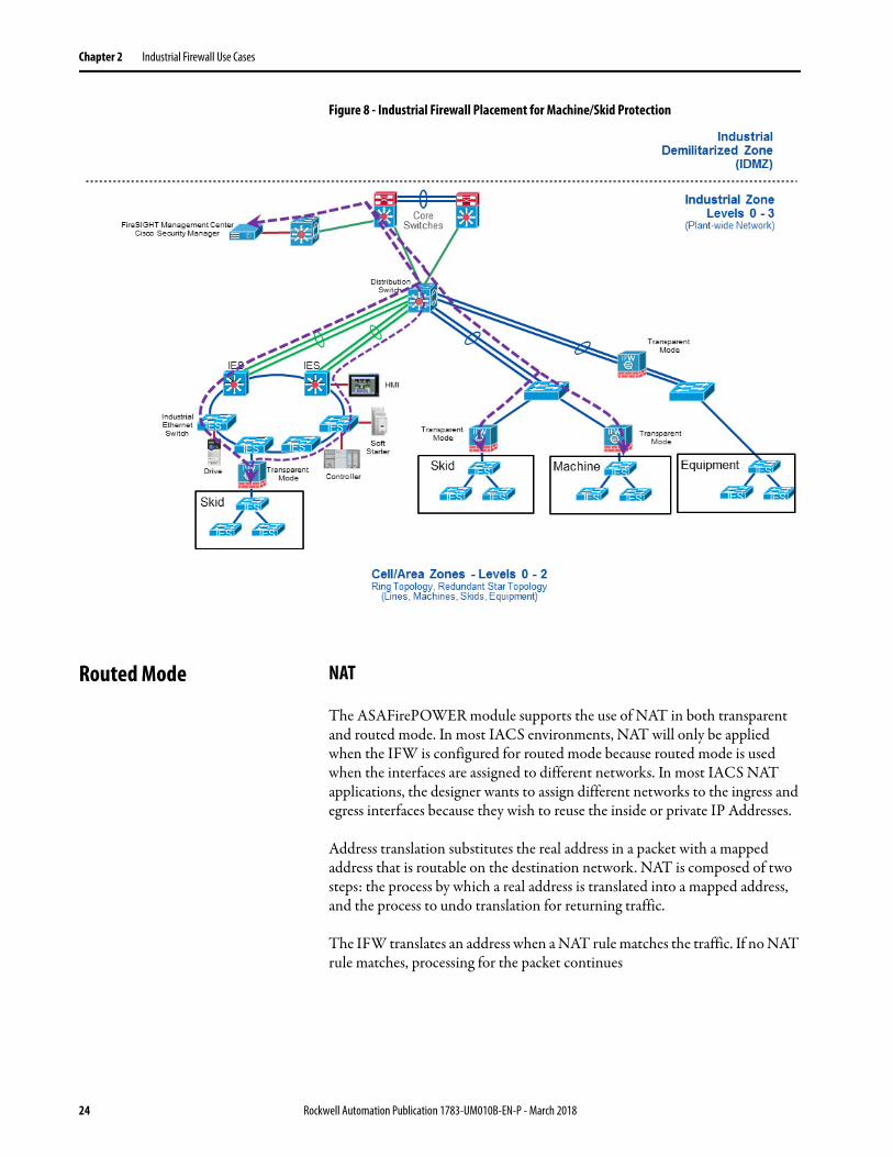
Machine/Skid Protection The machine/skid protection use case is used to separate a machine, skid or unit from a higher level network. This may be to support different security requirements between the larger network and the machine/skid or to restrict ingress and egress traffic. In this placement, the IFW can be run in either transparent or routed mode (refer to the corresponding subsection for details).
Transparent Mode
As shown in Figure 2-14 below, the Transparent Mode firewalls are placed between a larger network and a grouping of automation equipment that act as a machine, skid or unit. In each case, the IFW acts as an ingress and egress point to the machine/skid where traffic can be monitored or controlled through firewall or DPI security policies.
Rockwell Automation Publication 1783-UM010B-EN-P - March 2018 23
Chapter 2 Industrial Firewall Use Cases
Figure 8 - Industrial Firewall Placement for Machine/Skid Protection
Routed Mode NAT
The ASAFirePOWER module supports the use of NAT in both transparent and routed mode. In most IACS environments, NAT will only be applied when the IFW is configured for routed mode because routed mode is used when the interfaces are assigned to different networks. In most IACS NAT applications, the designer wants to assign different networks to the ingress and egress interfaces because they wish to reuse the inside or private IP Addresses.
Address translation substitutes the real address in a packet with a mapped address that is routable on the destination network. NAT is composed of two steps: the process by which a real address is translated into a mapped address, and the process to undo translation for returning traffic.
The IFW translates an address when a NAT rule matches the traffic. If no NAT rule matches, processing for the packet continues
24 Rockwell Automation Publication 1783-UM010B-EN-P - March 2018
Industrial Firewall Use Cases Chapter 2
Considerations
Before implementing the IFW in a machine/skid protection architecture, it is recommended that the designer understand and document:
• Ingress and egress traffic source and destination host communications. For example, IP Addresses of controllers, HMI, engineering workstations and all communications that enter or leave the machine / skid must be known so firewall and DPI security policies can be configured.
• Ingress and egress traffic source and destination protocols must be known to configure the firewall and DPI rules.
• Ingress and egress traffic volume (refer to performance subsections within Industrial Firewall Deployment Considerations section)
• Redundancy and availability requirements. For example, when considering high availability, one must consider the security considerations while in hardware bypass mode.
• Hardware bypass is only supported when the IFW is placed inline with an access link. When the IFW is placed inline with a trunk link, hardware bypass is not supported.
Rockwell Automation Publication 1783-UM010B-EN-P - March 2018 25
Chapter 2 Industrial Firewall Use Cases
Redundant Star Cell/Area Zone Protection
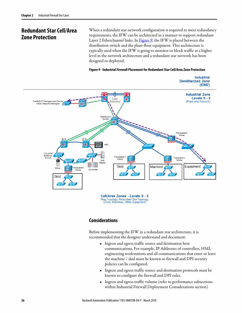
When a redundant star network configuration is required to meet redundancy requirements, the IFW can be architected in a manner to support redundant Layer 2 Etherchannel links. In Figure 9, the IFW is placed between the distribution switch and the plant floor equipment. This architecture is typically used when the IFW is going to monitor or block traffic at a higher level in the network architecture and a redundant star network has been designed or deployed.
Figure 9 - Industrial Firewall Placement for Redundant Star Cell/Area Zone Protection
Considerations
Before implementing the IFW in a redundant star architecture, it is recommended that the designer understand and document:
• Ingress and egress traffic source and destination host communications. For example, IP Addresses of controllers, HMI, engineering workstations and all communications that enter or leave the machine / skid must be known so firewall and DPI security policies can be configured.
• Ingress and egress traffic source and destination protocols must be known to configure the firewall and DPI rules.
• Ingress and egress traffic volume (refer to performance subsections within Industrial Firewall Deployment Considerations section)
26 Rockwell Automation Publication 1783-UM010B-EN-P - March 2018
Industrial Firewall Use Cases Chapter 2
• Redundancy and availability requirements. For example, when the IFW is configured with trunk ports, then hardware bypass mode is not available in this architecture.
• Hardware bypass is only supported when the IFW is placed inline with an access link. When the IFW is placed inline with a trunk link, hardware bypass is not supported.
Ring Cell/Area Zone Protection
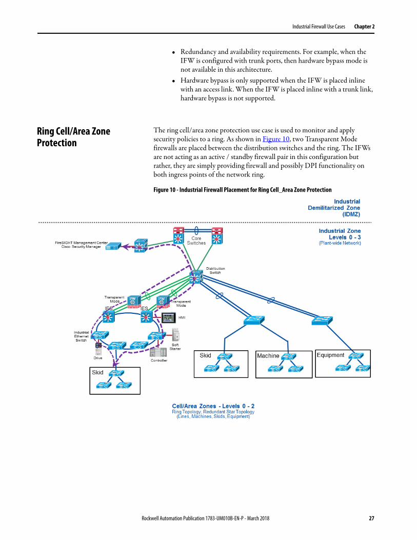
The ring cell/area zone protection use case is used to monitor and apply security policies to a ring. As shown in Figure 10, two Transparent Mode firewalls are placed between the distribution switches and the ring. The IFWs are not acting as an active / standby firewall pair in this configuration but rather, they are simply providing firewall and possibly DPI functionality on both ingress points of the network ring.
Figure 10 - Industrial Firewall Placement for Ring Cell_Area Zone Protection
Rockwell Automation Publication 1783-UM010B-EN-P - March 2018 27
Chapter 2 Industrial Firewall Use Cases
Considerations
Before implementing the IFW in a ring cell/area zone protection architecture, it is recommended that the designer understand and document:
• Ingress and egress traffic source and destination host communications. For example, IP Addresses of controllers, HMI, engineering workstations and all communications that enter or leave the machine / skid must be known so firewall and DPI security policies can be configured.
• Ingress and egress traffic source and destination protocols must be known to configure the firewall and DPI rules.
• Ingress and egress traffic volume (refer to performance subsections within Industrial Firewall Deployment Considerations section)
• Redundancy and availability requirements. In this use case, the ports are configured for Layer 3 Etherchannel.
• Hardware bypass is supported when the IFW is placed inline with a Layer 3 link.
IMPORTANT While it is a valid use case, implementing ring cell/area zone protection using the IFW as described in this section is not recommended due to architectural limitations of this deployment. Since active/standby pairing of the IFWs is not supported in this use case, when one IFW is disrupted, its connection state information will be lost. Any persistent connections that were established via the disrupted IFW will need to time out, then re-establish via the remaining IFW, resulting in significant communication downtime.
28 Rockwell Automation Publication 1783-UM010B-EN-P - March 2018
Industrial Firewall Use Cases Chapter 2
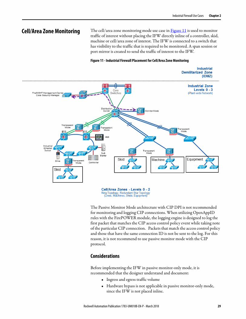
Cell/Area Zone Monitoring The cell/area zone monitoring mode use case in Figure 11 is used to monitor traffic of interest without placing the IFW directly inline of a controller, skid, machine or cell/area zone of interest. The IFW is connected to a switch that has visibility to the traffic that is required to be monitored. A span session or port mirror is created to send the traffic of interest to the IFW.
Figure 11 - Industrial Firewall Placement for Cell/Area Zone Monitoring
The Passive Monitor Mode architecture with CIP DPI is not recommended for monitoring and logging CIP connections. When utilizing OpenAppID rules with the FirePOWER module, the logging engine is designed to log the first packet that matches the CIP access control policy event while taking note of the particular CIP connection. Packets that match the access control policy and those that have the same connection ID is not be sent to the log. For this reason, it is not recommend to use passive monitor mode with the CIP protocol.
Considerations
Before implementing the IFW in passive monitor-only mode, it is recommended that the designer understand and document:
• Ingress and egress traffic volume• Hardware bypass is not applicable in passive monitor-only mode,
since the IFW is not placed inline.
Rockwell Automation Publication 1783-UM010B-EN-P - March 2018 29
Chapter 2 Industrial Firewall Use Cases
Time Synchronization In addition to the initial setup steps, the IFW must be configured with information on where to obtain its time synchronization data from. The firewall and FirePOWER components of the IFW have separate settings for time, and both must be configured independently.
To configure time synchronization for the firewall component, complete the following steps:
1. Click Configuration at the top left, then Device Setup at the bottom left. From the Device Setup pane, select System Time > NTP.
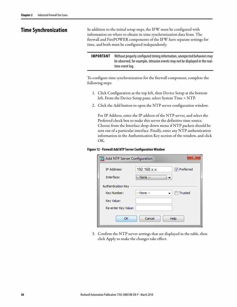
2. Click the Add button to open the NTP server configuration window.
For IP Address, enter the IP address of the NTP server, and select the Preferred check box to make this server the definitive time source. Choose from the Interface drop-down menu if NTP packets should be sent out of a particular interface. Finally, enter any NTP authentication information in the Authentication Key section of the window, and click OK.
Figure 12 - Firewall Add NTP Server Configuration Window
3. Confirm the NTP server settings that are displayed in the table, then click Apply to make the changes take effect.
IMPORTANT Without properly configured timing information, unexpected behaviors may be observed, for example, intrusion events may not be displayed in the real-time event log.
30 Rockwell Automation Publication 1783-UM010B-EN-P - March 2018
Industrial Firewall Use Cases Chapter 2
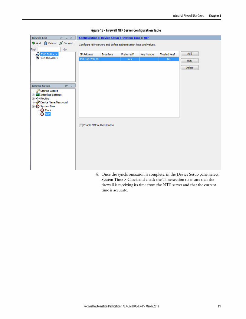
Figure 13 - Firewall NTP Server Configuration Table
4. Once the synchronization is complete, in the Device Setup pane, select System Time > Clock and check the Time section to ensure that the firewall is receiving its time from the NTP server and that the current time is accurate.
Rockwell Automation Publication 1783-UM010B-EN-P - March 2018 31
Chapter 2 Industrial Firewall Use Cases
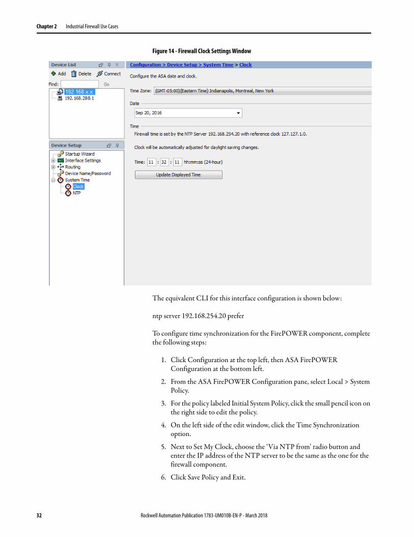
Figure 14 - Firewall Clock Settings Window
The equivalent CLI for this interface configuration is shown below:
ntp server 192.168.254.20 prefer
To configure time synchronization for the FirePOWER component, complete the following steps:
1. Click Configuration at the top left, then ASA FirePOWER Configuration at the bottom left.
2. From the ASA FirePOWER Configuration pane, select Local > System Policy.
3. For the policy labeled Initial System Policy, click the small pencil icon on the right side to edit the policy.
4. On the left side of the edit window, click the Time Synchronization option.
5. Next to Set My Clock, choose the ‘Via NTP from’ radio button and enter the IP address of the NTP server to be the same as the one for the firewall component.
6. Click Save Policy and Exit.
32 Rockwell Automation Publication 1783-UM010B-EN-P - March 2018
Industrial Firewall Use Cases Chapter 2
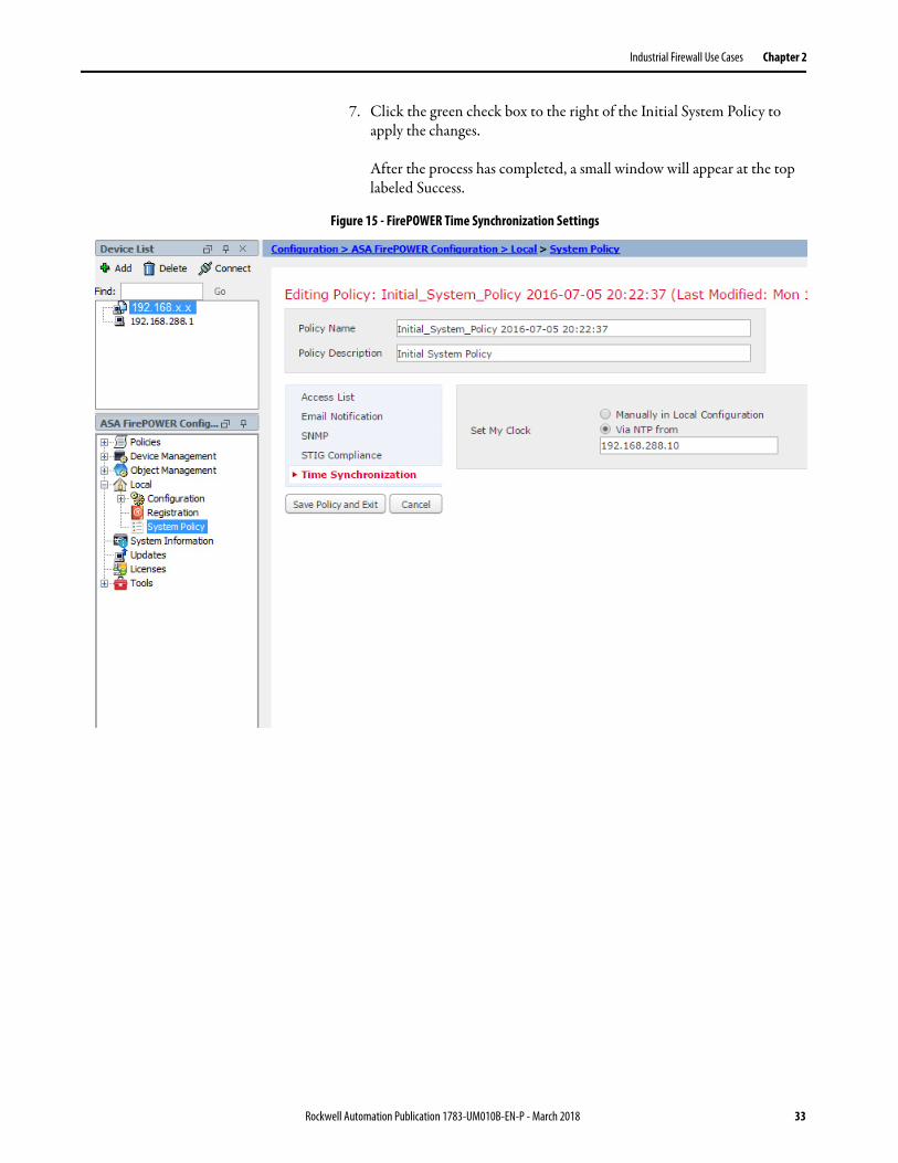
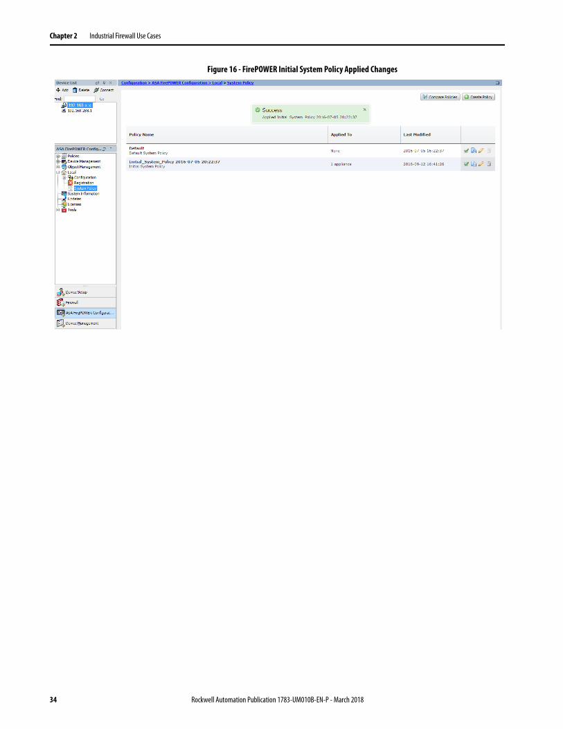
7. Click the green check box to the right of the Initial System Policy to apply the changes.
After the process has completed, a small window will appear at the top labeled Success.
Figure 15 - FirePOWER Time Synchronization Settings
Rockwell Automation Publication 1783-UM010B-EN-P - March 2018 33
Chapter 2 Industrial Firewall Use Cases
Figure 16 - FirePOWER Initial System Policy Applied Changes
34 Rockwell Automation Publication 1783-UM010B-EN-P - March 2018
Industrial Firewall Use Cases Chapter 2
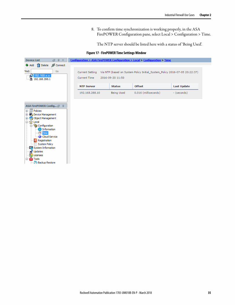
8. To confirm time synchronization is working properly, in the ASA FirePOWER Configuration pane, select Local > Configuration > Time.
The NTP server should be listed here with a status of ‘Being Used’.
Figure 17 - FirePOWER Time Settings Window
Rockwell Automation Publication 1783-UM010B-EN-P - March 2018 35

Chapter 2 Industrial Firewall Use Cases
Notes:
36 Rockwell Automation Publication 1783-UM010B-EN-P - March 2018
Chapter 3
Configure the Security Appliance
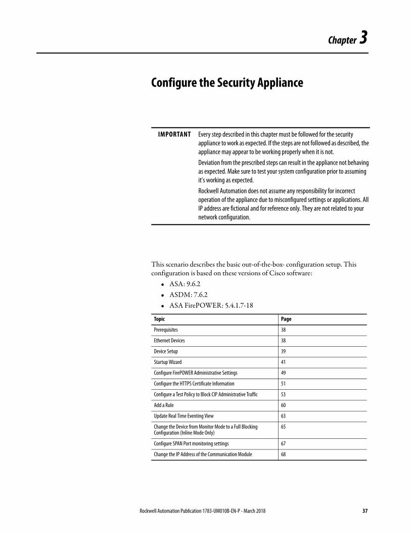
This scenario describes the basic out-of-the-box- configuration setup. This configuration is based on these versions of Cisco software:
• ASA: 9.6.2• ASDM: 7.6.2• ASA FirePOWER: 5.4.1.7-18
IMPORTANT Every step described in this chapter must be followed for the security appliance to work as expected. If the steps are not followed as described, the appliance may appear to be working properly when it is not.Deviation from the prescribed steps can result in the appliance not behaving as expected. Make sure to test your system configuration prior to assuming it's working as expected. Rockwell Automation does not assume any responsibility for incorrect operation of the appliance due to misconfigured settings or applications. All IP address are fictional and for reference only. They are not related to your network configuration.
Topic Page
Prerequisites 38
Ethernet Devices 38
Device Setup 39
Startup Wizard 41
Configure FirePOWER Administrative Settings 49
Configure the HTTPS Certificate Information 51
Configure a Test Policy to Block CIP Administrative Traffic 53
Add a Rule 60
Update Real Time Eventing View 63
Change the Device from Monitor Mode to a Full Blocking Configuration (Inline Mode Only)
65
Configure SPAN Port monitoring settings 67
Change the IP Address of the Communication Module 68
Rockwell Automation Publication 1783-UM010B-EN-P - March 2018 37
Chapter 3 Configure the Security Appliance
Prerequisites Follow these prerequisite steps before you attempt to configure the Stratix™ 5950 Security Appliance. There are two deployment configurations described in this chapter. You need to select a deployment configuration mode: Inline or SPAN Port.
All steps listed in this chapter apply to both configurations unless otherwise noted.
You will need:• Deployment Configuration Guide• Power supply• Console cable• Ethernet cable• Device • Personal computer
Ethernet Devices Identify the Ethernet devices that you are going to connect to the device: switch, servers, and workstations or personal computers. Verify that each device has a network interface card (NIC) for connecting to Ethernet ports.
It is required that you partially configure the device using Cisco ASA commands through the console port. You need an ASCII terminal or a personal computer that is running terminal emulation software to connect to the console port.
1. Make sure that you are using a personal computer configured with a supported operating system. For a list of supported operating systems, see the release notes at:
http://www.cisco.com/c/en/us/td/docs/security/asdm/7_6/release/notes/rn76.html
2. Install the latest version of Java.
Go to https://www.java.com
3. Install a Terminal Emulator, such as PuTTY.
4. Obtain the Stratix 5950 security appliance from the factory, no cables connected.
5. Obtain the cable, DB9-to-RJ45 that is shipped with the appliance.
6. Determine the Management network for the device, for example: 10.0.1.0.24
7. Contact your Network Administrator, and obtain two IP addresses in the Management network.a. IP address 1 is for the ASA management IP address, for example:
10.0.1.1
38 Rockwell Automation Publication 1783-UM010B-EN-P - March 2018
Configure the Security Appliance Chapter 3
b. IP address 2 is for the SFR management IP address, for example: 10.0.1.2
8. Determine the network that you want to use the appliance to monitor, for example: 192.168.1.0/24 (Inline configuration mode only)
9. Contact your Network Administrator and obtain an IP address in the network that you want to monitor, for example: 192.168.1.218 (Inline configuration mode only)
10. Obtain a list of DNS servers from your Network Administrator.
Device Setup Follow these steps to configure the Cisco ASA software.
1. Set NIC on your computer to DHCP.
Next, you need to connect the Management interface on the Stratix 5950 security appliance to the NIC on your computer.
2. Connect the serial cable from Console port on the security appliance to the serial port on your computer.
3. Apply power to the security appliance.
4. Wait until the EIP Mod status indicator turns solid green.
The green status indicator flashes until complete, about 5 minutes.
5. Connect to https://169.254.0.1/admin.
Ignore self-signed certificate warnings.
6. Click either Install ASDM Launcher or Run ASDM, depends on what your system displays.
If you are required to click Install ASDM Launcher, steps 8…10 apply.
7. When prompted for a username and password, leave the fields blank and click login.
8. Run the dm-launcher.msi file that was downloaded.
9. Install using the default options.
Cisco ASDM-IDM Launcher launches automatically.
Rockwell Automation Publication 1783-UM010B-EN-P - March 2018 39
Chapter 3 Configure the Security Appliance
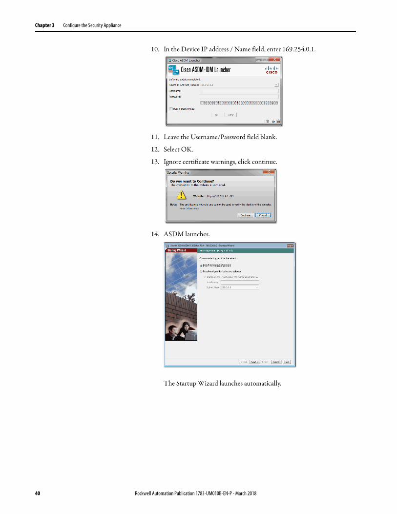
10. In the Device IP address / Name field, enter 169.254.0.1.
11. Leave the Username/Password field blank.
12. Select OK.
13. Ignore certificate warnings, click continue.
14. ASDM launches.
The Startup Wizard launches automatically.
Stratix 5950 ASDM 7.6(2) for ASA - 169.226.0.2 - Startup Wizard
40 Rockwell Automation Publication 1783-UM010B-EN-P - March 2018

Configure the Security Appliance Chapter 3
Startup Wizard
Follow these steps to complete the configuration by using the Startup Wizard. Be sure to complete all screens.
1. Choose a starting point and click Next.
2. Enter the host name and the domain name of the ASA.
Stratix 5950 ASDM 7.6(2) for ASA - 169.226.0.2 - Startup Wizard
Stratix 5950 ASDM 7.6(2) for ASA - 169.226.0.2 - Startup Wizard
Rockwell Automation Publication 1783-UM010B-EN-P - March 2018 41

Chapter 3 Configure the Security Appliance
3. Provide password information.
4. On the Management IP address Configuration dialog box (Step 2of 13).a. Inline Mode Only:
Enter the IP address and Subnet Mask from the range of the network you want to monitor.
b. SPAN Port Mode Only:
Enter a temporary/dummy IP address that is not in the management network.
The Subnet Mask must be changed to something other than 255.255.255.255. For example, IP Address = 2.2.2.2, Subnet Mask = 255.255.255.0
IMPORTANT This address is NOT the Management IP addresses in the Management network.
Stratix 5950 ASDM 7.6(2) for ASA - 169.226.0.2 - Startup Wizard
Stratix 5950 ASDM 7.6(2) for ASA - 169.226.0.2 - Startup Wizard
10.51.72.223
255.255.252.0
42 Rockwell Automation Publication 1783-UM010B-EN-P - March 2018
Configure the Security Appliance Chapter 3
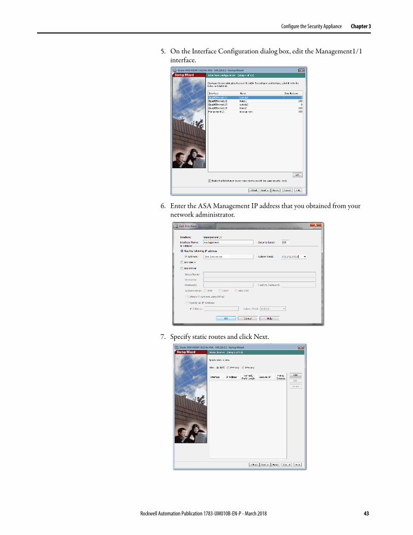
5. On the Interface Configuration dialog box, edit the Management1/1 interface.
6. Enter the ASA Management IP address that you obtained from your network administrator.
7. Specify static routes and click Next.
Stratix 5950 ASDM 7.6(2) for ASA - 169.226.0.2 - Startup Wizard
1xx.1xx.xx.xx
Stratix 5950 ASDM 7.6(2) for ASA - 169.226.0.2 - Startup Wizard
Rockwell Automation Publication 1783-UM010B-EN-P - March 2018 43
Chapter 3 Configure the Security Appliance
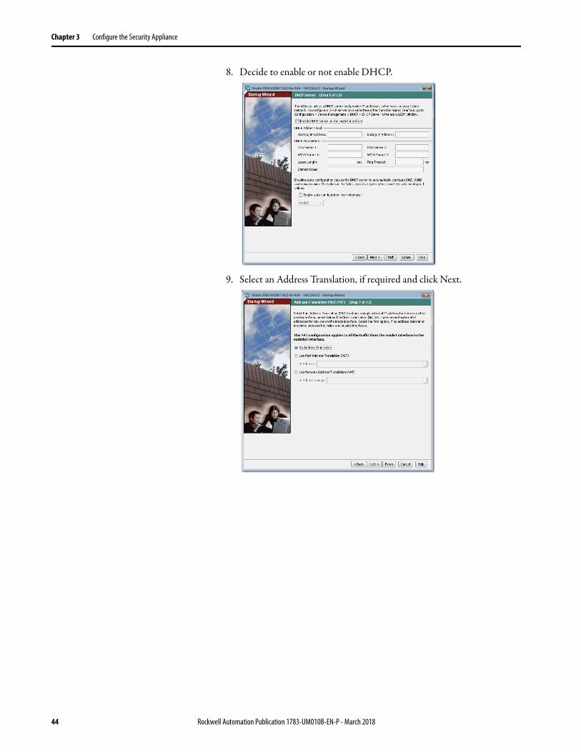
8. Decide to enable or not enable DHCP.
9. Select an Address Translation, if required and click Next.
Stratix 5950 ASDM 7.6(2) for ASA - 169.226.0.2 - Startup Wizard
Stratix 5950 ASDM 7.6(2) for ASA - 169.226.0.2 - Startup Wizard
44 Rockwell Automation Publication 1783-UM010B-EN-P - March 2018
Configure the Security Appliance Chapter 3
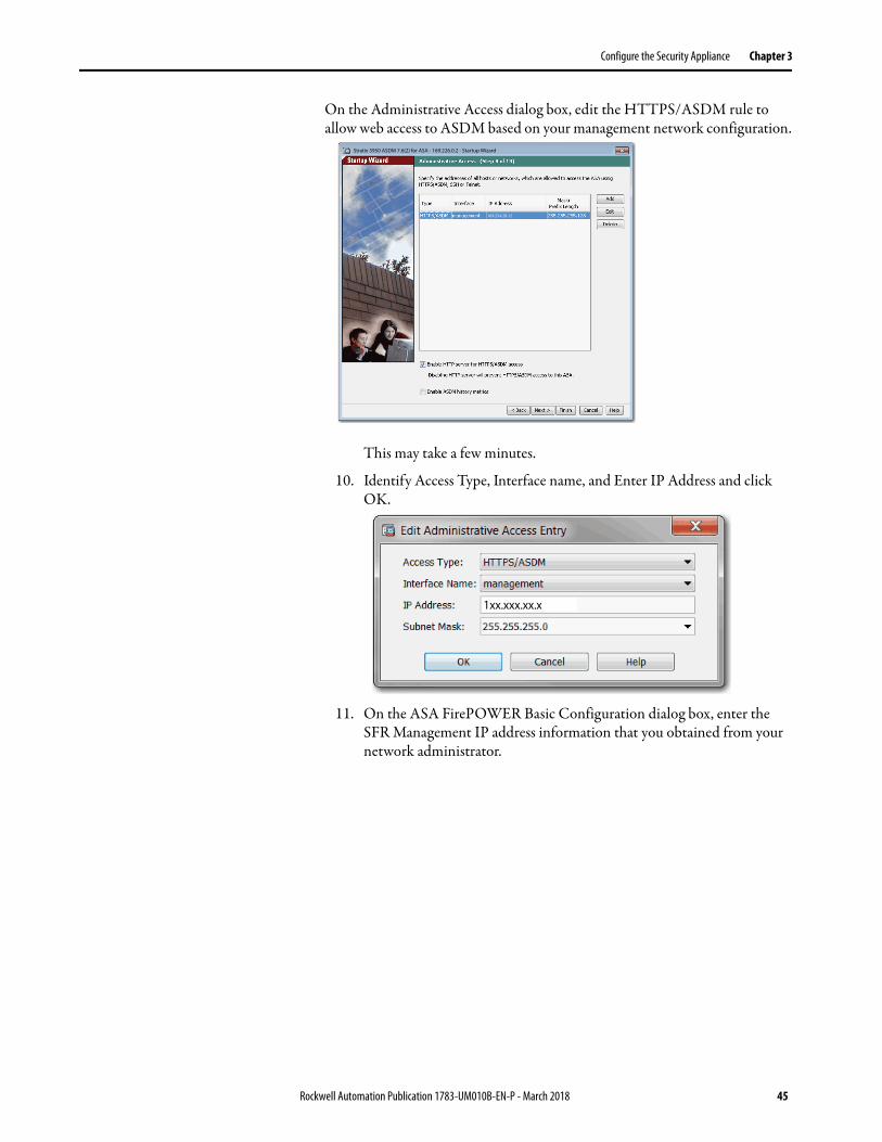
On the Administrative Access dialog box, edit the HTTPS/ASDM rule to allow web access to ASDM based on your management network configuration.
This may take a few minutes.
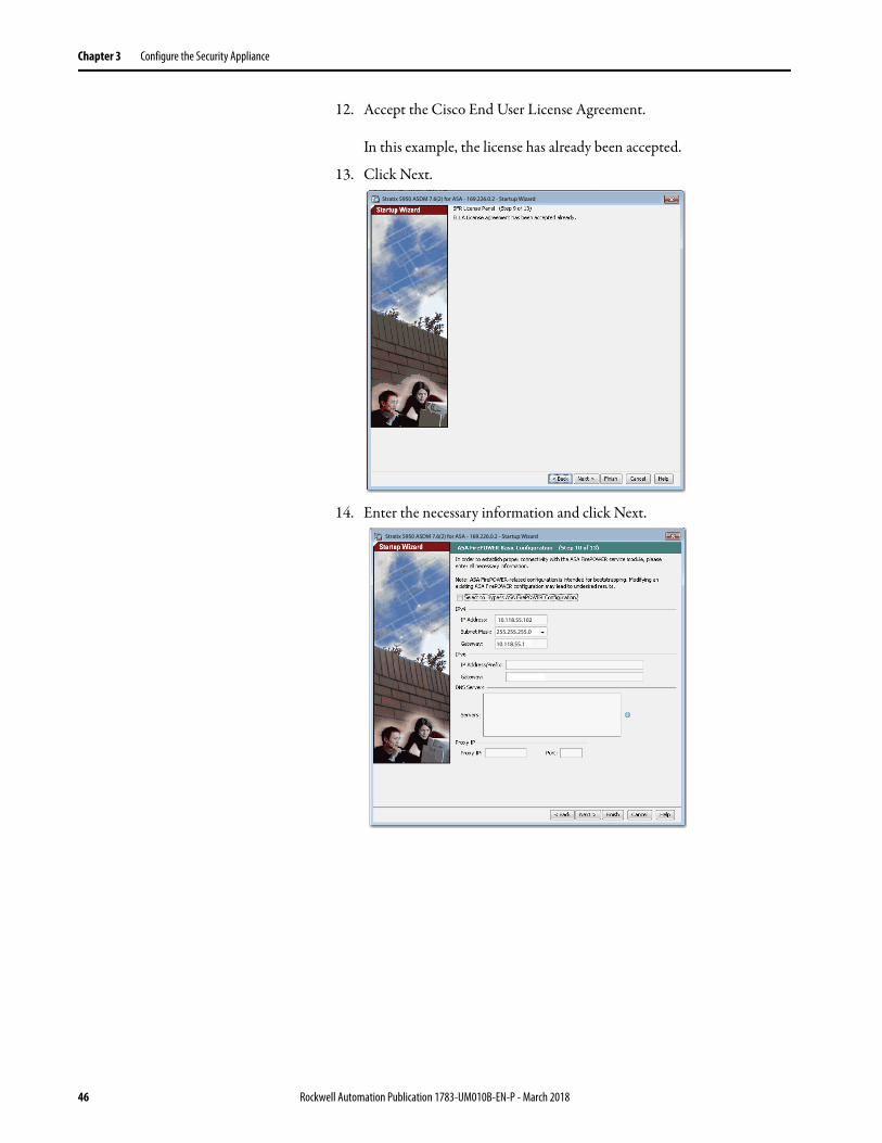
10. Identify Access Type, Interface name, and Enter IP Address and click OK.
11. On the ASA FirePOWER Basic Configuration dialog box, enter the SFR Management IP address information that you obtained from your network administrator.
Stratix 5950 ASDM 7.6(2) for ASA - 169.226.0.2 - Startup Wizard
169.254.20.12
1xx.xxx.xx.x
Rockwell Automation Publication 1783-UM010B-EN-P - March 2018 45
Chapter 3 Configure the Security Appliance
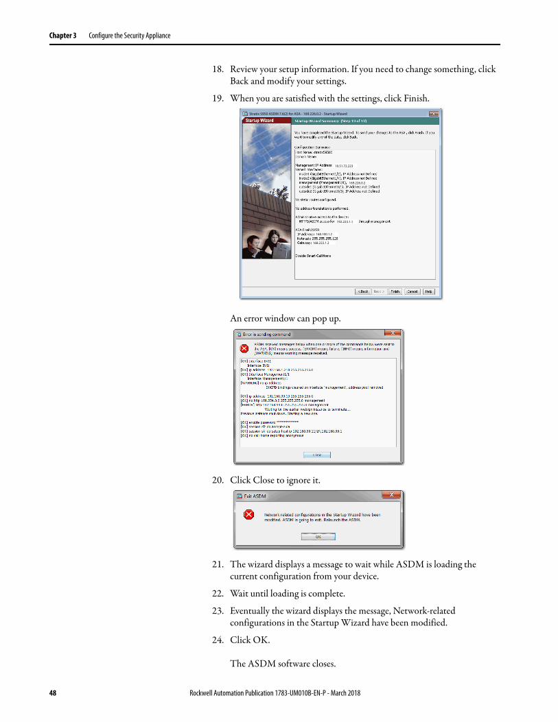
12. Accept the Cisco End User License Agreement.
In this example, the license has already been accepted.
13. Click Next.
14. Enter the necessary information and click Next.
Stratix 5950 ASDM 7.6(2) for ASA - 169.226.0.2 - Startup Wizard
Stratix 5950 ASDM 7.6(2) for ASA - 169.226.0.2 - Startup Wizard
10.118.55.102
10.118.55.1
255.255.255.0
46 Rockwell Automation Publication 1783-UM010B-EN-P - March 2018

Configure the Security Appliance Chapter 3
15. Enable Auto Update for ASA, if needed and click Next.
16. On Startup Wizard Summary click Finish.
'The ‘Management IP Address’ listed in the ‘Configuration Summary’ is NOT the Management IP addresses in the Management network. This is the IP address of the network that you want to monitor.
The wizard displays a wait message for a couple minutes.
17. Enable Smart Call, if desired and click Next.
Stratix 5950 ASDM 7.6(2) for ASA - 169.226.0.2 - Startup Wizard
Stratix 5950 ASDM 7.6(2) for ASA - 169.226.0.2 - Startup Wizard
Rockwell Automation Publication 1783-UM010B-EN-P - March 2018 47
Chapter 3 Configure the Security Appliance
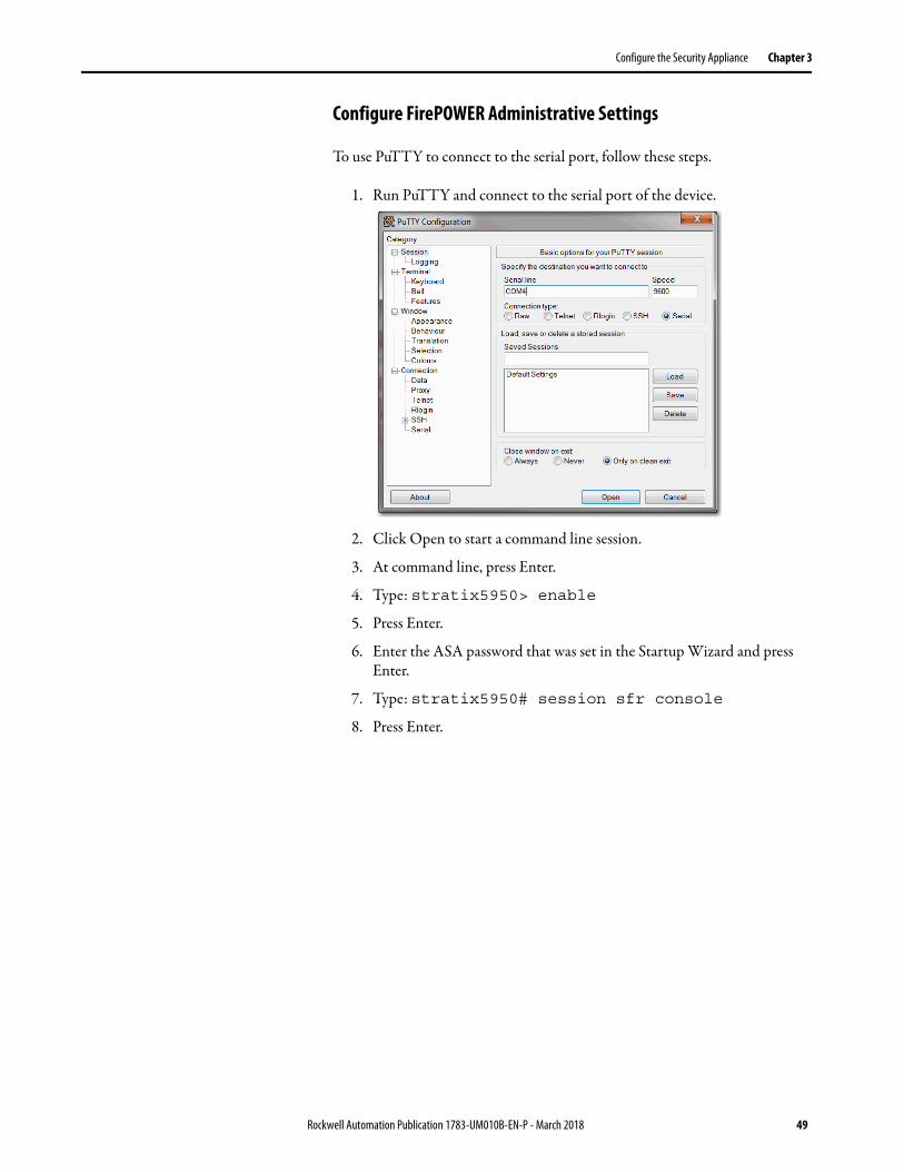
18. Review your setup information. If you need to change something, click Back and modify your settings.
19. When you are satisfied with the settings, click Finish.
An error window can pop up.
20. Click Close to ignore it.
21. The wizard displays a message to wait while ASDM is loading the current configuration from your device.
22. Wait until loading is complete.
23. Eventually the wizard displays the message, Network-related configurations in the Startup Wizard have been modified.
24. Click OK.
The ASDM software closes.
Stratix 5950 ASDM 7.6(2) for ASA - 169.226.0.2 - Startup Wizard
10.51.72.223
169.226.0.2
168.100.1.2
192.223.1.1
168.222.1.2
48 Rockwell Automation Publication 1783-UM010B-EN-P - March 2018
Configure the Security Appliance Chapter 3
Configure FirePOWER Administrative Settings
To use PuTTY to connect to the serial port, follow these steps.
1. Run PuTTY and connect to the serial port of the device.
2. Click Open to start a command line session.
3. At command line, press Enter.
4. Type: stratix5950> enable
5. Press Enter.
6. Enter the ASA password that was set in the Startup Wizard and press Enter.
7. Type: stratix5950# session sfr console
8. Press Enter.
Rockwell Automation Publication 1783-UM010B-EN-P - March 2018 49
Chapter 3 Configure the Security Appliance
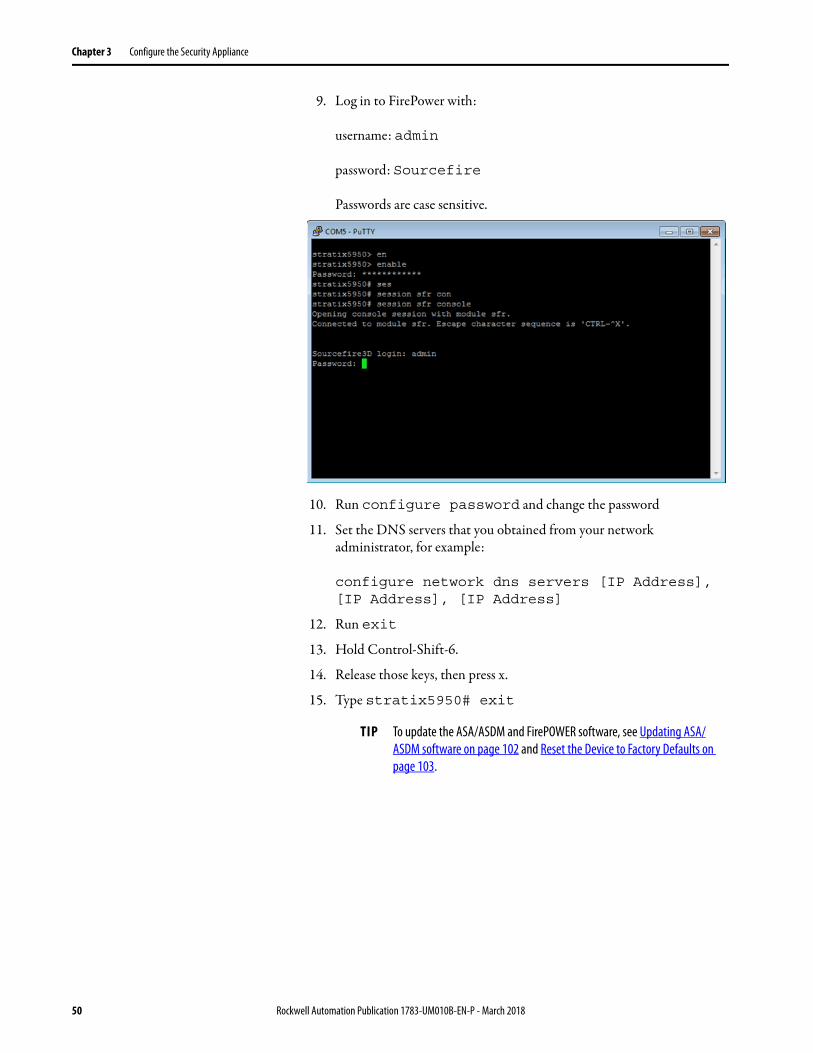
9. Log in to FirePower with:
username: admin
password: Sourcefire
Passwords are case sensitive.
10. Run configure password and change the password
11. Set the DNS servers that you obtained from your network administrator, for example:
configure network dns servers [IP Address], [IP Address], [IP Address]
12. Run exit
13. Hold Control-Shift-6.
14. Release those keys, then press x.
15. Type stratix5950# exit
TIP To update the ASA/ASDM and FirePOWER software, see Updating ASA/ASDM software on page 102 and Reset the Device to Factory Defaults on page 103.
50 Rockwell Automation Publication 1783-UM010B-EN-P - March 2018
Configure the Security Appliance Chapter 3
Configure the HTTPS Certificate Information
Follow these steps to configure the HTTPS certificate.
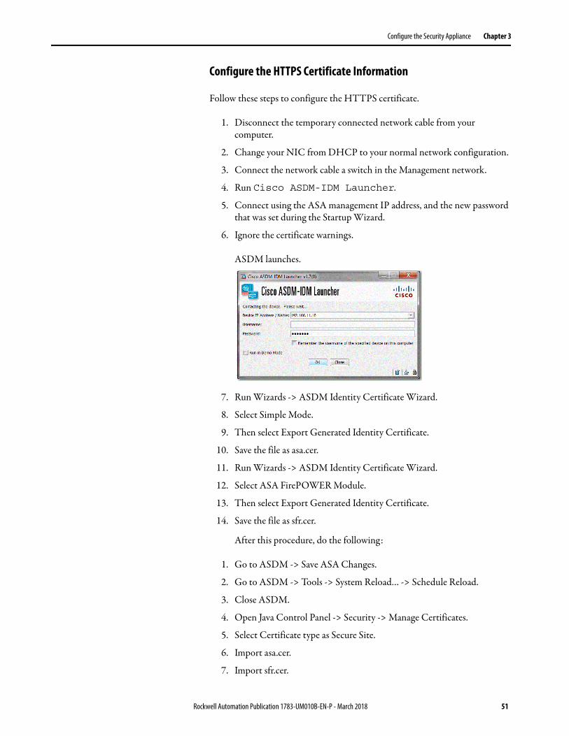
1. Disconnect the temporary connected network cable from your computer.
2. Change your NIC from DHCP to your normal network configuration.
3. Connect the network cable a switch in the Management network.
4. Run Cisco ASDM-IDM Launcher.
5. Connect using the ASA management IP address, and the new password that was set during the Startup Wizard.
6. Ignore the certificate warnings.
ASDM launches.
7. Run Wizards -> ASDM Identity Certificate Wizard.
8. Select Simple Mode.
9. Then select Export Generated Identity Certificate.
10. Save the file as asa.cer.
11. Run Wizards -> ASDM Identity Certificate Wizard.
12. Select ASA FirePOWER Module.
13. Then select Export Generated Identity Certificate.
14. Save the file as sfr.cer.
After this procedure, do the following:
1. Go to ASDM -> Save ASA Changes.
2. Go to ASDM -> Tools -> System Reload… -> Schedule Reload.
3. Close ASDM.
4. Open Java Control Panel -> Security -> Manage Certificates.
5. Select Certificate type as Secure Site.
6. Import asa.cer.
7. Import sfr.cer.
Rockwell Automation Publication 1783-UM010B-EN-P - March 2018 51

Chapter 3 Configure the Security Appliance
8. Wait until the EIP Mod status indicator on the Stratix 5950 security appliance is solid green.
This takes about 5 minutes.
9. Run Cisco ASDM-IDM Launcher.
There should be no certificate warning dialogs.
ASDM opens.
52 Rockwell Automation Publication 1783-UM010B-EN-P - March 2018

Configure the Security Appliance Chapter 3
Configure a Test Policy to Block CIP Administrative Traffic
Configure a test policy to verify the expected behavior of CIP DPI functionality. This test policy verifies that the CIP RA Administrative traffic is blocked from passing through the device.
To configure a test policy to block CIP admin traffic, follow these steps.
1. ASDM -> Configuration -> ASA FirePOWER Configuration -> Policies -> Access Control Policy -> New Policy.
2. Name the policy, for example, Block_CIP_Admin_Policy
3. Change the Default Action to Intrusion Prevention.
4. Click Store ASA FirePOWER Changes.
Rockwell Automation Publication 1783-UM010B-EN-P - March 2018 53
Chapter 3 Configure the Security Appliance
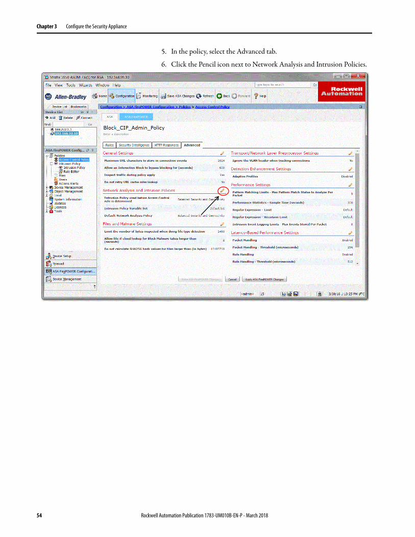
5. In the policy, select the Advanced tab.
6. Click the Pencil icon next to Network Analysis and Intrusion Policies.
54 Rockwell Automation Publication 1783-UM010B-EN-P - March 2018
Configure the Security Appliance Chapter 3
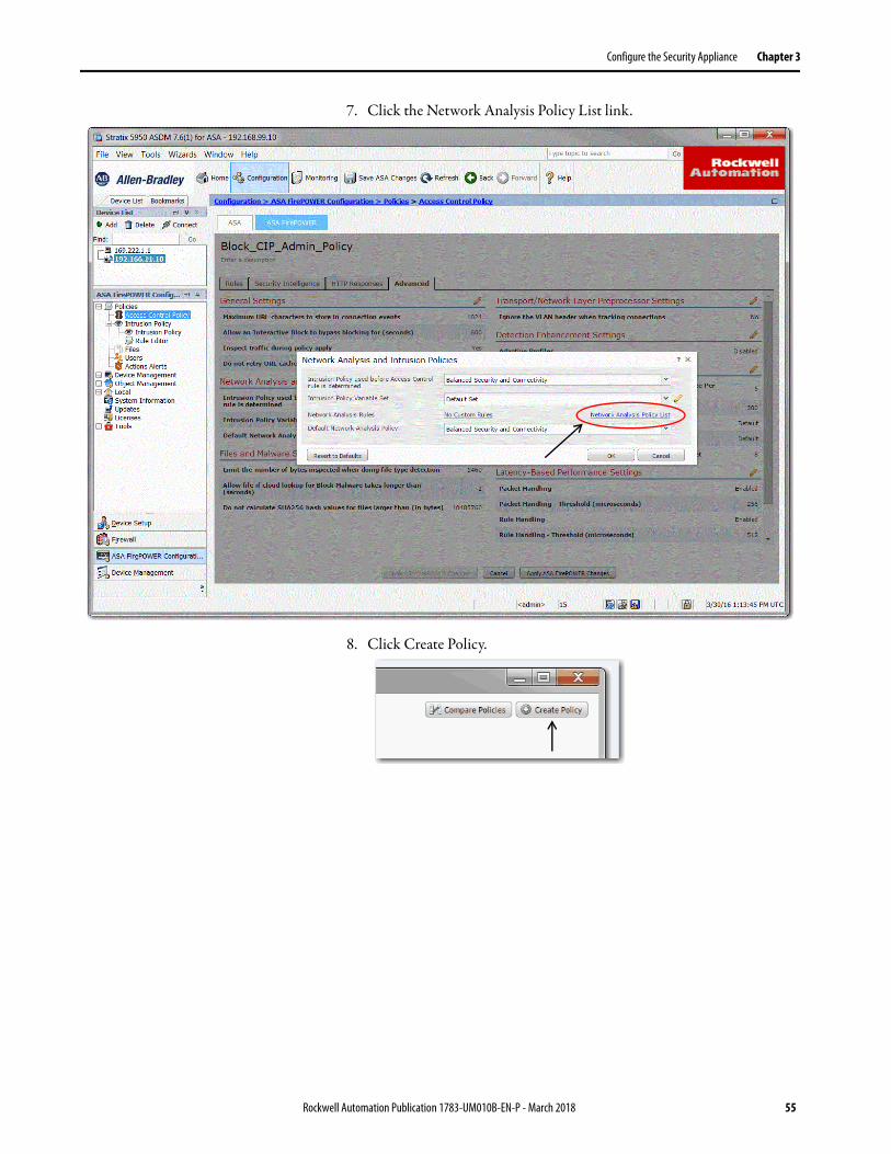
7. Click the Network Analysis Policy List link.
8. Click Create Policy.
Rockwell Automation Publication 1783-UM010B-EN-P - March 2018 55
Chapter 3 Configure the Security Appliance
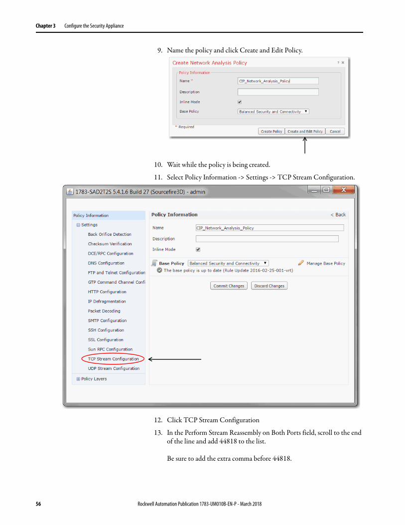
9. Name the policy and click Create and Edit Policy.
10. Wait while the policy is being created.
11. Select Policy Information -> Settings -> TCP Stream Configuration.
12. Click TCP Stream Configuration
13. In the Perform Stream Reassembly on Both Ports field, scroll to the end of the line and add 44818 to the list.
Be sure to add the extra comma before 44818.
56 Rockwell Automation Publication 1783-UM010B-EN-P - March 2018
Configure the Security Appliance Chapter 3
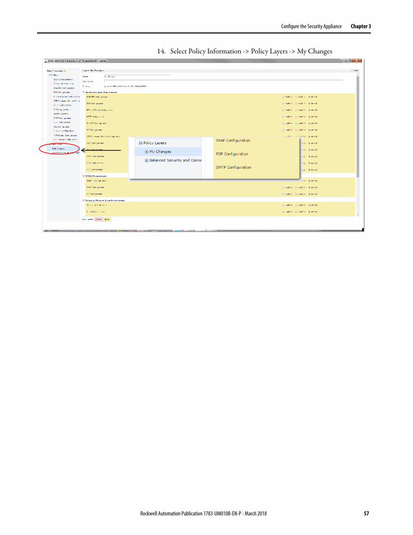
14. Select Policy Information -> Policy Layers -> My Changes
Rockwell Automation Publication 1783-UM010B-EN-P - March 2018 57
Chapter 3 Configure the Security Appliance
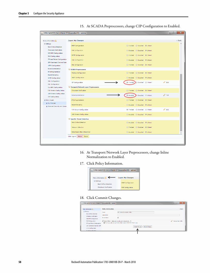
15. At SCADA Preprocessors, change CIP Configuration to Enabled.
16. At Transport/Network Layer Preprocessors, change Inline Normalization to Enabled.
17. Click Policy Information.
18. Click Commit Changes.
58 Rockwell Automation Publication 1783-UM010B-EN-P - March 2018
Configure the Security Appliance Chapter 3
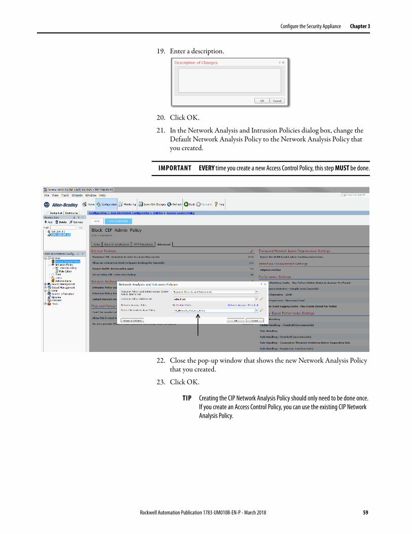
19. Enter a description.
20. Click OK.
21. In the Network Analysis and Intrusion Policies dialog box, change the Default Network Analysis Policy to the Network Analysis Policy that you created.
22. Close the pop-up window that shows the new Network Analysis Policy that you created.
23. Click OK.
IMPORTANT EVERY time you create a new Access Control Policy, this step MUST be done.
TIP Creating the CIP Network Analysis Policy should only need to be done once. If you create an Access Control Policy, you can use the existing CIP Network Analysis Policy.
Rockwell Automation Publication 1783-UM010B-EN-P - March 2018 59
Chapter 3 Configure the Security Appliance
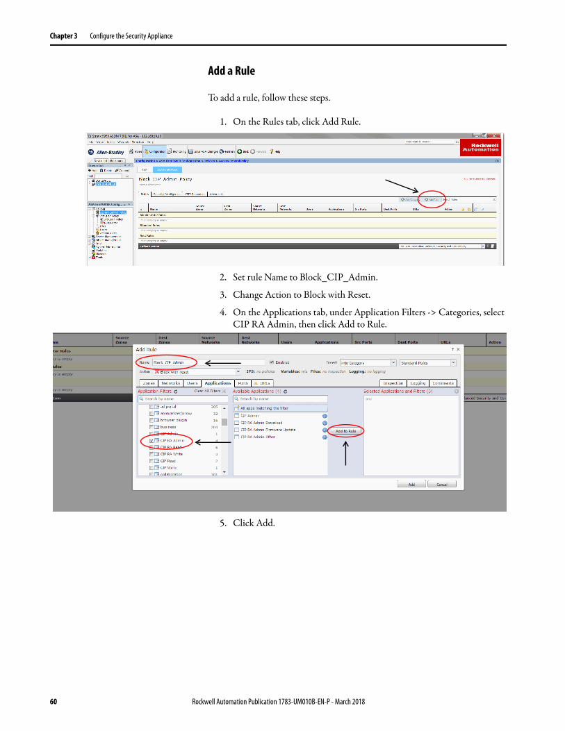
Add a Rule
To add a rule, follow these steps.
1. On the Rules tab, click Add Rule.
2. Set rule Name to Block_CIP_Admin.
3. Change Action to Block with Reset.
4. On the Applications tab, under Application Filters -> Categories, select CIP RA Admin, then click Add to Rule.
5. Click Add.
60 Rockwell Automation Publication 1783-UM010B-EN-P - March 2018
Configure the Security Appliance Chapter 3
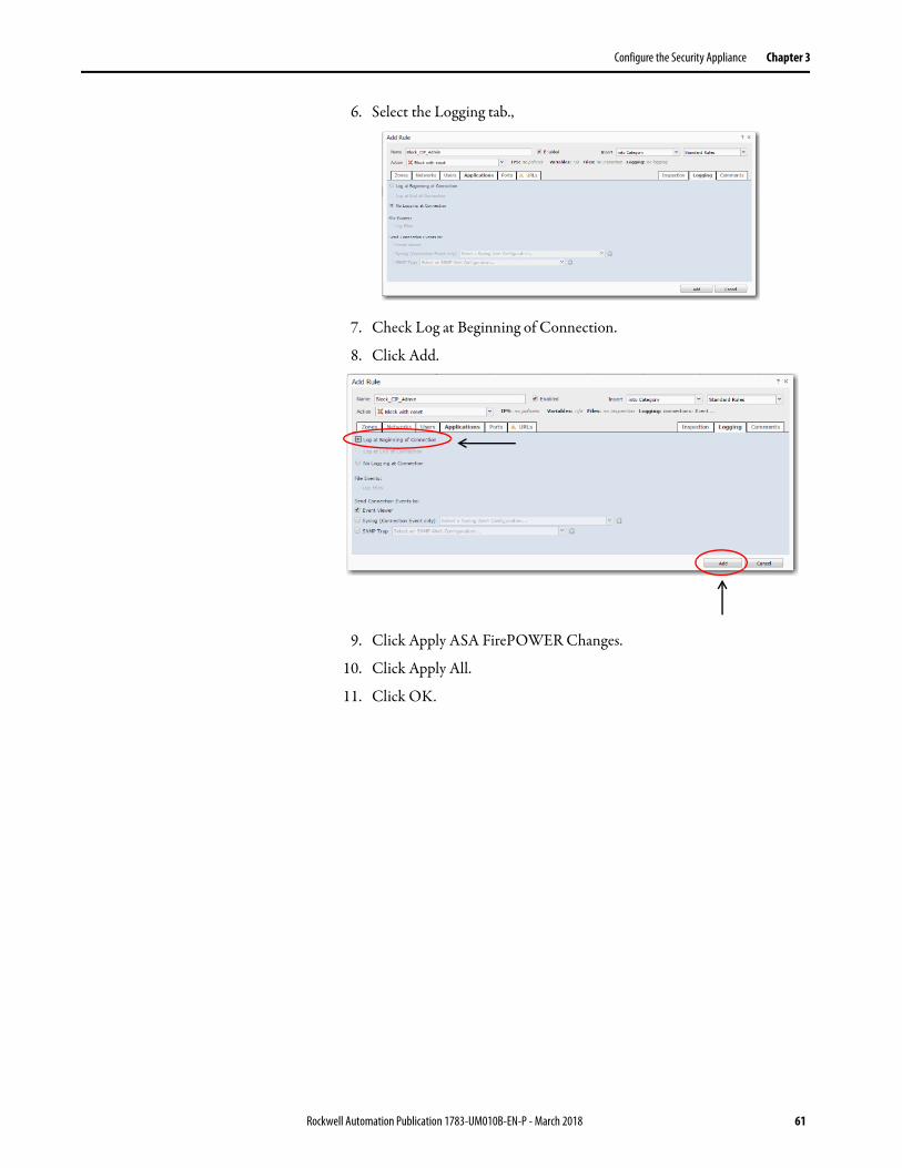
6. Select the Logging tab.,
7. Check Log at Beginning of Connection.
8. Click Add.
9. Click Apply ASA FirePOWER Changes.
10. Click Apply All.
11. Click OK.
Rockwell Automation Publication 1783-UM010B-EN-P - March 2018 61
Chapter 3 Configure the Security Appliance
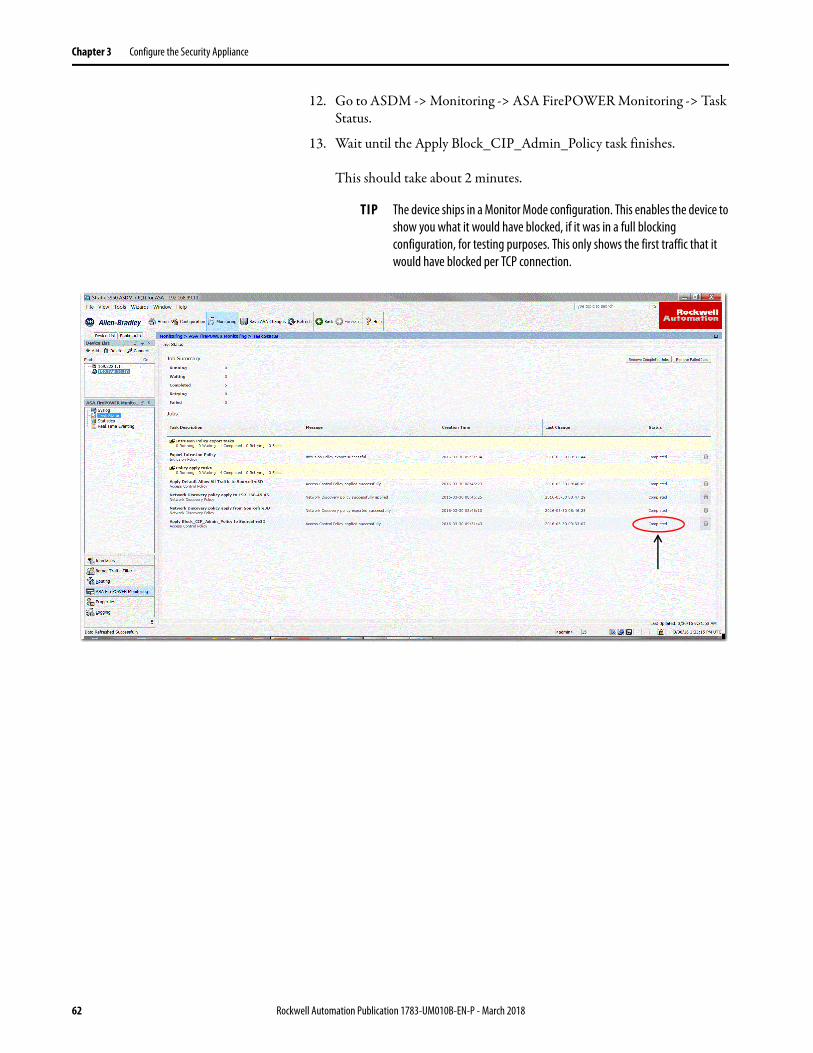
12. Go to ASDM -> Monitoring -> ASA FirePOWER Monitoring -> Task Status.
13. Wait until the Apply Block_CIP_Admin_Policy task finishes.
This should take about 2 minutes.
TIP The device ships in a Monitor Mode configuration. This enables the device to show you what it would have blocked, if it was in a full blocking configuration, for testing purposes. This only shows the first traffic that it would have blocked per TCP connection.
62 Rockwell Automation Publication 1783-UM010B-EN-P - March 2018
Configure the Security Appliance Chapter 3
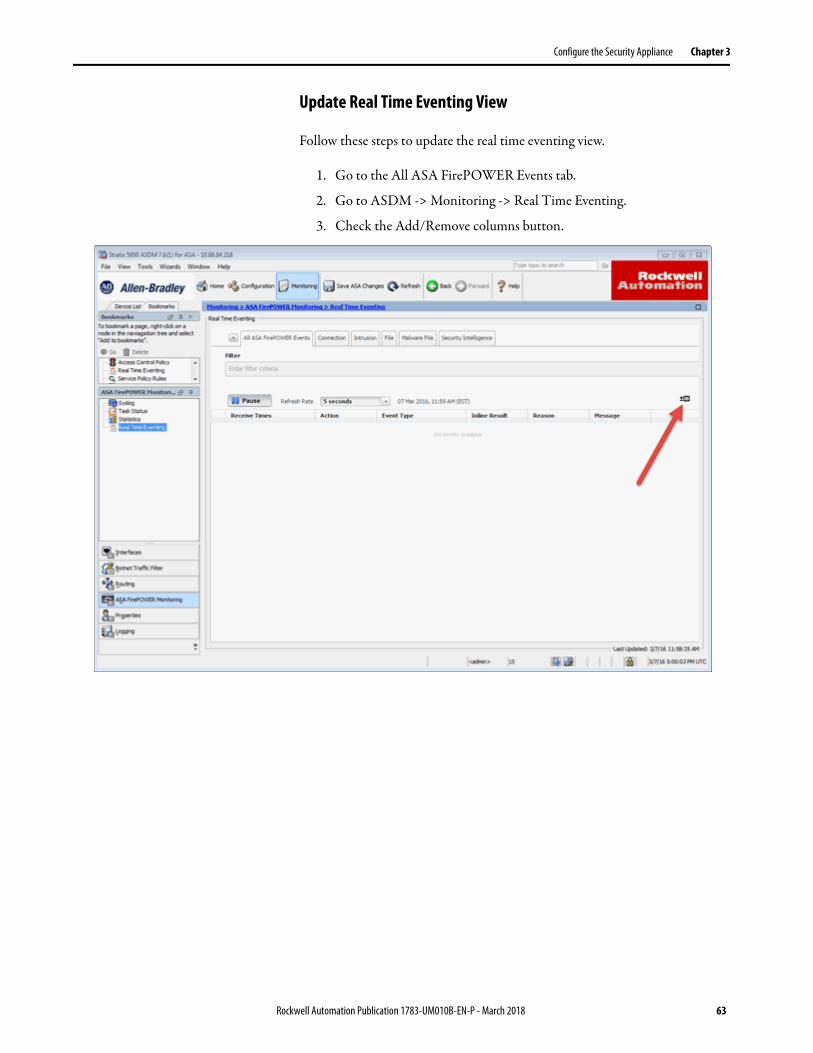
Update Real Time Eventing View
Follow these steps to update the real time eventing view.
1. Go to the All ASA FirePOWER Events tab.
2. Go to ASDM -> Monitoring -> Real Time Eventing.
3. Check the Add/Remove columns button.
Rockwell Automation Publication 1783-UM010B-EN-P - March 2018 63
Chapter 3 Configure the Security Appliance
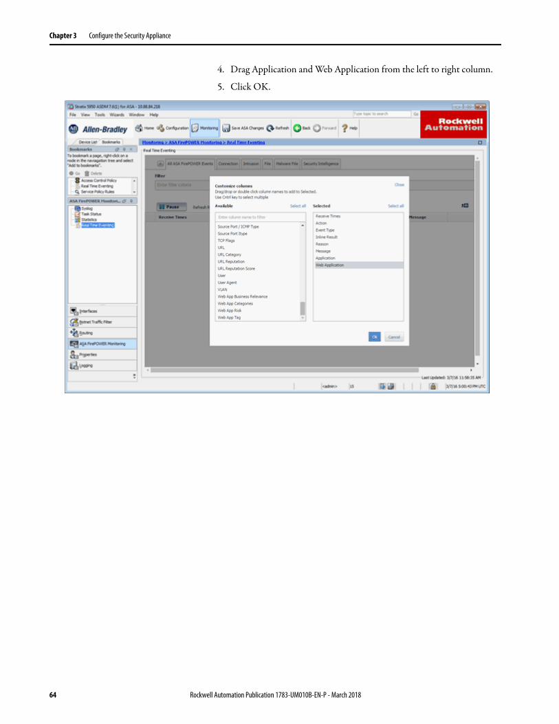
4. Drag Application and Web Application from the left to right column.
5. Click OK.
64 Rockwell Automation Publication 1783-UM010B-EN-P - March 2018
Configure the Security Appliance Chapter 3
Change the Device from Monitor Mode to a Full Blocking Configuration (Inline Mode Only)
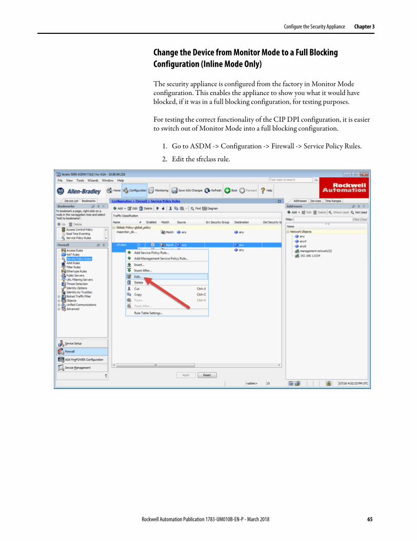
The security appliance is configured from the factory in Monitor Mode configuration. This enables the appliance to show you what it would have blocked, if it was in a full blocking configuration, for testing purposes.
For testing the correct functionality of the CIP DPI configuration, it is easier to switch out of Monitor Mode into a full blocking configuration.
1. Go to ASDM -> Configuration -> Firewall -> Service Policy Rules.
2. Edit the sfrclass rule.
Rockwell Automation Publication 1783-UM010B-EN-P - March 2018 65
Chapter 3 Configure the Security Appliance
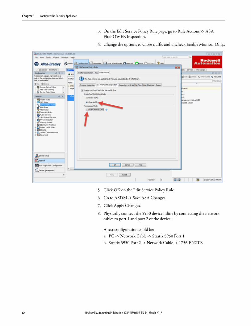
3. On the Edit Service Policy Rule page, go to Rule Actions -> ASA FirePOWER Inspection.
4. Change the options to Close traffic and uncheck Enable Monitor Only..
5. Click OK on the Edit Service Policy Rule.
6. Go to ASDM -> Save ASA Changes.
7. Click Apply Changes.
8. Physically connect the 5950 device inline by connecting the network cables to port 1 and port 2 of the device.
A test configuration could be: a. PC -> Network Cable -> Stratix 5950 Port 1b. Stratix 5950 Port 2 -> Network Cable -> 1756-EN2TR
66 Rockwell Automation Publication 1783-UM010B-EN-P - March 2018
Configure the Security Appliance Chapter 3
Configure SPAN Port monitoring settings
This section only applies to SPAN Port mode configuration only.
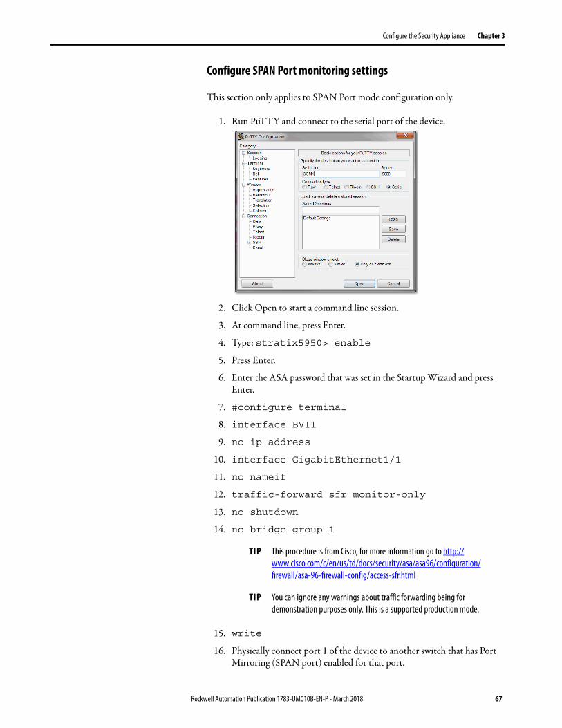
1. Run PuTTY and connect to the serial port of the device.
2. Click Open to start a command line session.
3. At command line, press Enter.
4. Type: stratix5950> enable
5. Press Enter.
6. Enter the ASA password that was set in the Startup Wizard and press Enter.
7. #configure terminal
8. interface BVI1
9. no ip address
10. interface GigabitEthernet1/1
11. no nameif
12. traffic-forward sfr monitor-only
13. no shutdown
14. no bridge-group 1
15. write
16. Physically connect port 1 of the device to another switch that has Port Mirroring (SPAN port) enabled for that port.
TIP This procedure is from Cisco, for more information go to http://www.cisco.com/c/en/us/td/docs/security/asa/asa96/configuration/firewall/asa-96-firewall-config/access-sfr.html
TIP You can ignore any warnings about traffic forwarding being for demonstration purposes only. This is a supported production mode.
Rockwell Automation Publication 1783-UM010B-EN-P - March 2018 67
Chapter 3 Configure the Security Appliance
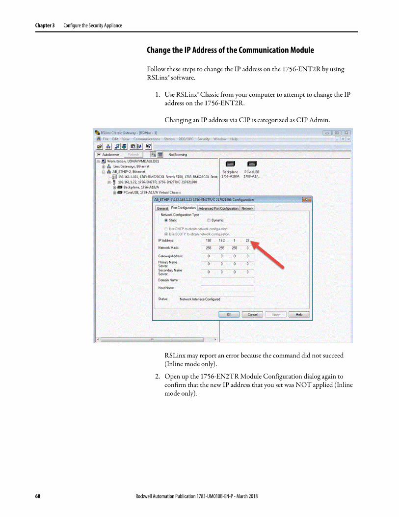
Change the IP Address of the Communication Module
Follow these steps to change the IP address on the 1756-ENT2R by using RSLinx® software.
1. Use RSLinx® Classic from your computer to attempt to change the IP address on the 1756-ENT2R.
Changing an IP address via CIP is categorized as CIP Admin.
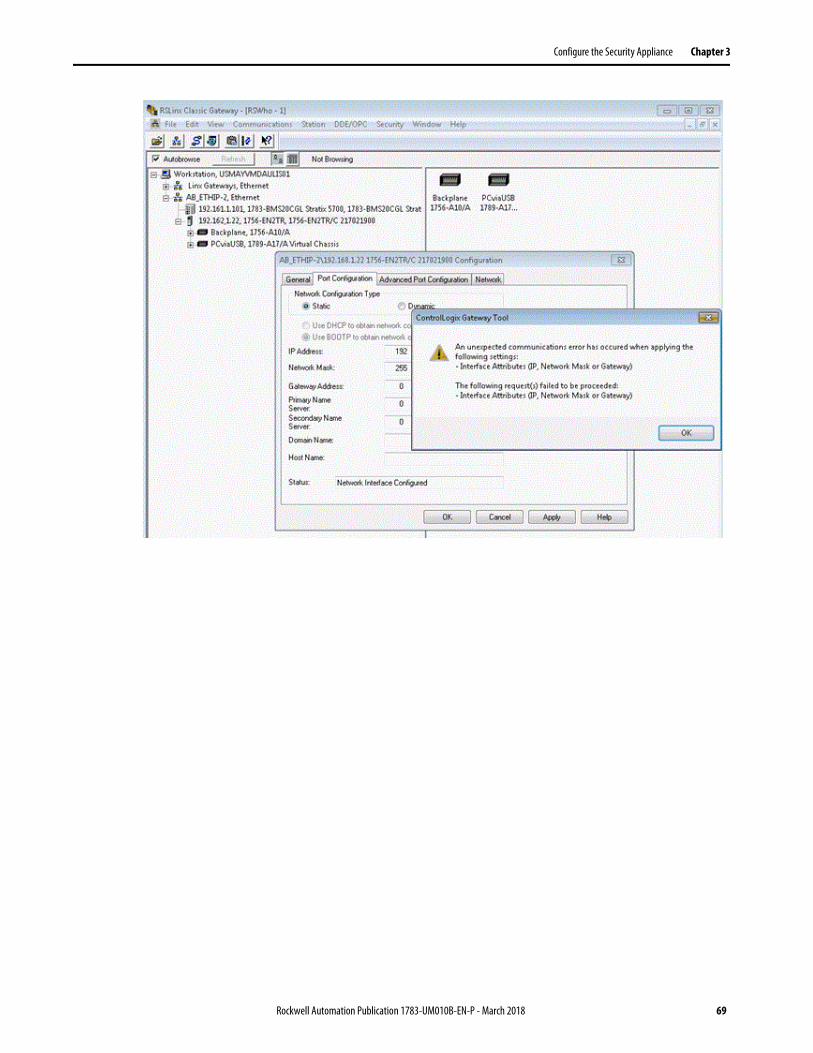
RSLinx may report an error because the command did not succeed (Inline mode only).
2. Open up the 1756-EN2TR Module Configuration dialog again to confirm that the new IP address that you set was NOT applied (Inline mode only).
68 Rockwell Automation Publication 1783-UM010B-EN-P - March 2018
Configure the Security Appliance Chapter 3
Rockwell Automation Publication 1783-UM010B-EN-P - March 2018 69
Chapter 3 Configure the Security Appliance
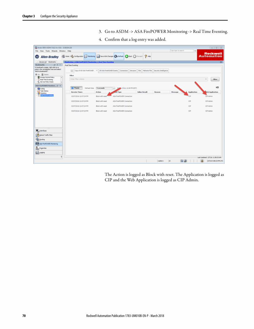
3. Go to ASDM -> ASA FirePOWER Monitoring -> Real Time Eventing.
4. Confirm that a log entry was added.
The Action is logged as Block with reset. The Application is logged as CIP and the Web Application is logged as CIP Admin.
70 Rockwell Automation Publication 1783-UM010B-EN-P - March 2018
Chapter 4
Monitor the Security Appliance
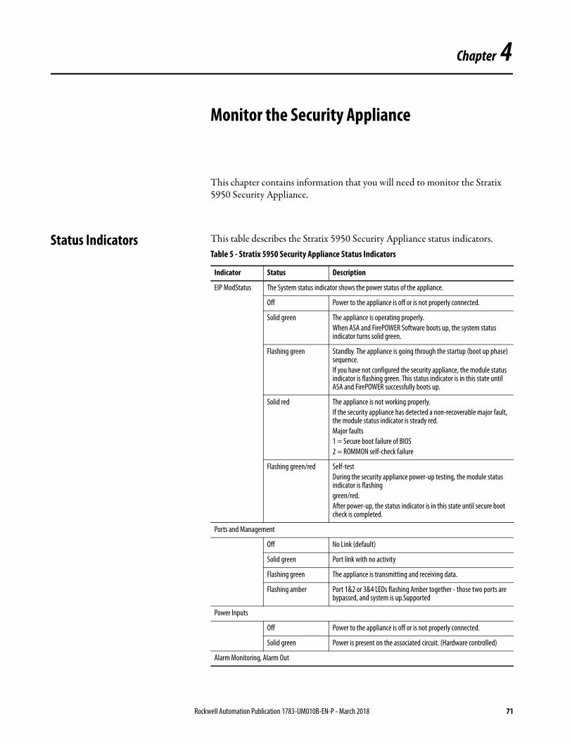
This chapter contains information that you will need to monitor the Stratix 5950 Security Appliance.
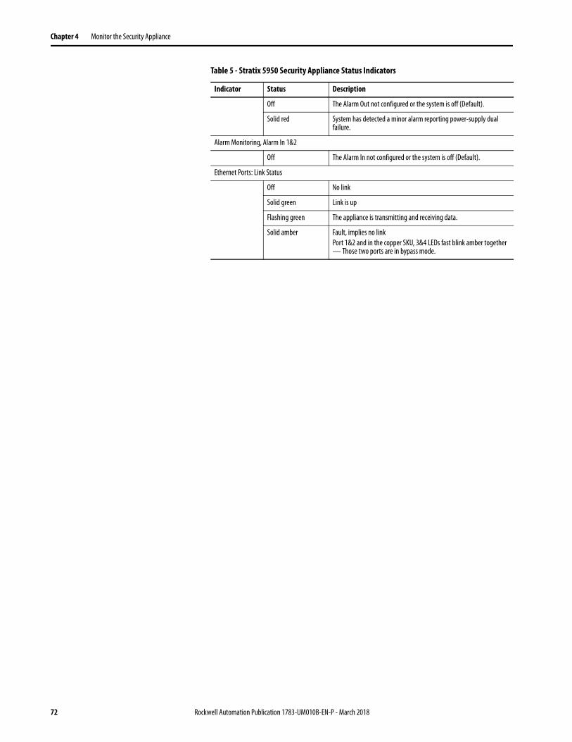
Status Indicators This table describes the Stratix 5950 Security Appliance status indicators.Table 5 - Stratix 5950 Security Appliance Status Indicators
Indicator Status Description
EIP ModStatus The System status indicator shows the power status of the appliance.
Off Power to the appliance is off or is not properly connected.
Solid green The appliance is operating properly.When ASA and FirePOWER Software boots up, the system status indicator turns solid green.
Flashing green Standby. The appliance is going through the startup (boot up phase) sequence.If you have not configured the security appliance, the module status indicator is flashing green. This status indicator is in this state until ASA and FirePOWER successfully boots up.
Solid red The appliance is not working properly.If the security appliance has detected a non-recoverable major fault, the module status indicator is steady red.Major faults1 = Secure boot failure of BIOS2 = ROMMON self-check failure
Flashing green/red Self-testDuring the security appliance power-up testing, the module status indicator is flashinggreen/red. After power-up, the status indicator is in this state until secure boot check is completed.
Ports and Management
Off No Link (default)
Solid green Port link with no activity
Flashing green The appliance is transmitting and receiving data.
Flashing amber Port 1&2 or 3&4 LEDs flashing Amber together - those two ports are bypassed, and system is up.Supported
Power Inputs
Off Power to the appliance is off or is not properly connected.
Solid green Power is present on the associated circuit. (Hardware controlled)
Alarm Monitoring, Alarm Out
Rockwell Automation Publication 1783-UM010B-EN-P - March 2018 71
Chapter 4 Monitor the Security Appliance
Off The Alarm Out not configured or the system is off (Default).
Solid red System has detected a minor alarm reporting power-supply dual failure.
Alarm Monitoring, Alarm In 1&2
Off The Alarm In not configured or the system is off (Default).
Ethernet Ports: Link Status
Off No link
Solid green Link is up
Flashing green The appliance is transmitting and receiving data.
Solid amber Fault, implies no linkPort 1&2 and in the copper SKU, 3&4 LEDs fast blink amber together — Those two ports are in bypass mode.
Table 5 - Stratix 5950 Security Appliance Status Indicators
Indicator Status Description
72 Rockwell Automation Publication 1783-UM010B-EN-P - March 2018
Chapter 5
Centralized Management
Overview Local management can get cumbersome when we need to manage many IFWs in the network. A centralized management enables consistent policy enforcement and quick troubleshooting of security events, offering summarized reports across the security deployment. A centralized interface helps organizations to scale efficiently and manage a wide range of security devices with improved visibility.
As explained in earlier sections, the IFW has two components: the firewall and FirePOWER module. Each component is managed separately. The FirePOWER component is managed by FireSIGHT Management Center, and the firewall component is managed by Cisco Security Manager (CSM). The following sections provide an overview of each application.
FireSIGHT Management Center
The Cisco FireSIGHT Management Center manages the FirePOWER module of the IFW. FireSIGHT Management Center is the administrative nerve center for a number of security products that incorporate FirePOWER technology. It provides complete and unified management of firewalls, application control, intrusion prevention, URL filtering, and advanced malware protection. The Management Center is the centralized point for event and policy management for the IFW platform.
The FireSIGHT Management Center provides extensive intelligence about the users, applications, devices, threats, and vulnerabilities that exist in your network. It also uses this information to analyze your network's vulnerabilities and provides tailored recommendations on what security policies to put in place and what security events you should investigate.
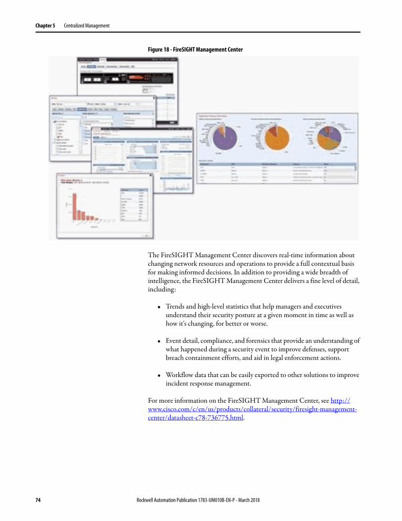
Figure 18 shows examples of the types of data that can be gathered using FireSIGHT Management Center.
Rockwell Automation Publication 1783-UM010B-EN-P - March 2018 73
Chapter 5 Centralized Management
Figure 18 - FireSIGHT Management Center
The FireSIGHT Management Center discovers real-time information about changing network resources and operations to provide a full contextual basis for making informed decisions. In addition to providing a wide breadth of intelligence, the FireSIGHT Management Center delivers a fine level of detail, including:
• Trends and high-level statistics that help managers and executives understand their security posture at a given moment in time as well as how it's changing, for better or worse.
• Event detail, compliance, and forensics that provide an understanding of what happened during a security event to improve defenses, support breach containment efforts, and aid in legal enforcement actions.
• Workflow data that can be easily exported to other solutions to improve incident response management.
For more information on the FireSIGHT Management Center, see http://www.cisco.com/c/en/us/products/collateral/security/firesight-management-center/datasheet-c78-736775.html.
74 Rockwell Automation Publication 1783-UM010B-EN-P - March 2018
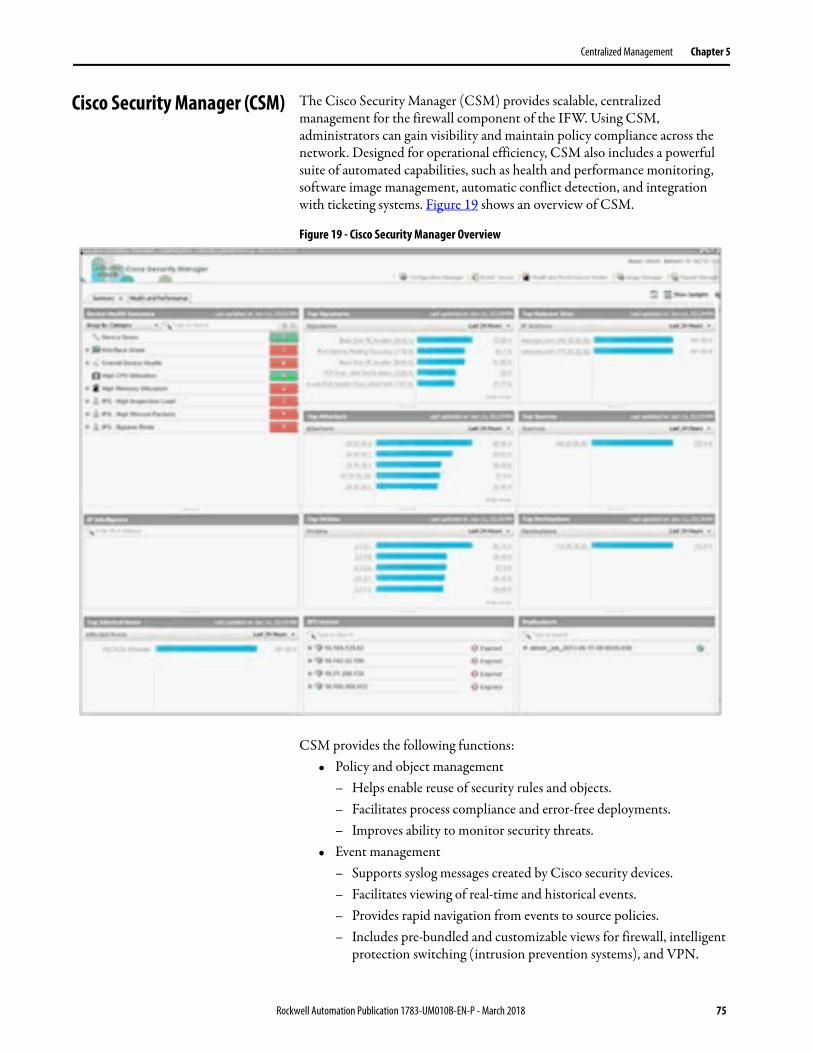
Centralized Management Chapter 5
Cisco Security Manager (CSM) The Cisco Security Manager (CSM) provides scalable, centralized management for the firewall component of the IFW. Using CSM, administrators can gain visibility and maintain policy compliance across the network. Designed for operational efficiency, CSM also includes a powerful suite of automated capabilities, such as health and performance monitoring, software image management, automatic conflict detection, and integration with ticketing systems. Figure 19 shows an overview of CSM.
Figure 19 - Cisco Security Manager Overview
CSM provides the following functions:• Policy and object management
– Helps enable reuse of security rules and objects.– Facilitates process compliance and error-free deployments.– Improves ability to monitor security threats.
• Event management– Supports syslog messages created by Cisco security devices.– Facilitates viewing of real-time and historical events.– Provides rapid navigation from events to source policies.– Includes pre-bundled and customizable views for firewall, intelligent
protection switching (intrusion prevention systems), and VPN.
Rockwell Automation Publication 1783-UM010B-EN-P - March 2018 75
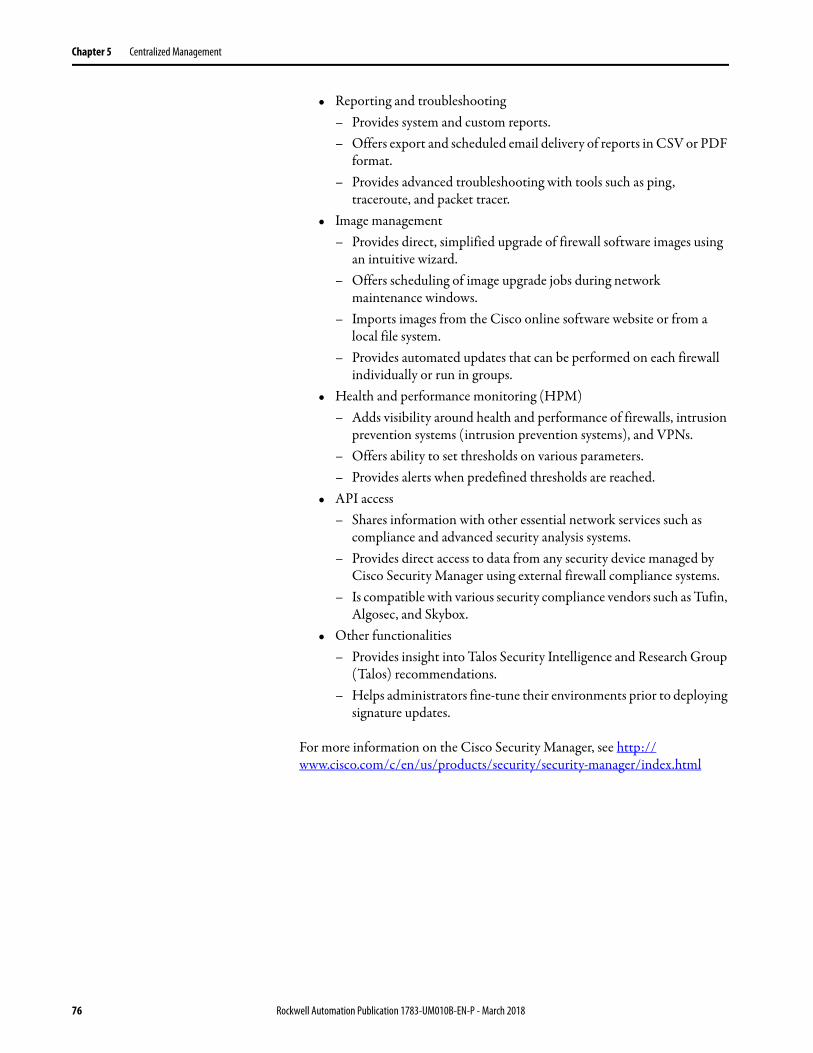
Chapter 5 Centralized Management
• Reporting and troubleshooting– Provides system and custom reports.– Offers export and scheduled email delivery of reports in CSV or PDF
format.– Provides advanced troubleshooting with tools such as ping,
traceroute, and packet tracer.• Image management
– Provides direct, simplified upgrade of firewall software images using an intuitive wizard.
– Offers scheduling of image upgrade jobs during network maintenance windows.
– Imports images from the Cisco online software website or from a local file system.
– Provides automated updates that can be performed on each firewall individually or run in groups.
• Health and performance monitoring (HPM)– Adds visibility around health and performance of firewalls, intrusion
prevention systems (intrusion prevention systems), and VPNs.– Offers ability to set thresholds on various parameters.– Provides alerts when predefined thresholds are reached.
• API access– Shares information with other essential network services such as
compliance and advanced security analysis systems.– Provides direct access to data from any security device managed by
Cisco Security Manager using external firewall compliance systems.– Is compatible with various security compliance vendors such as Tufin,
Algosec, and Skybox.• Other functionalities
– Provides insight into Talos Security Intelligence and Research Group (Talos) recommendations.
– Helps administrators fine-tune their environments prior to deploying signature updates.
For more information on the Cisco Security Manager, see http://www.cisco.com/c/en/us/products/security/security-manager/index.html
76 Rockwell Automation Publication 1783-UM010B-EN-P - March 2018
Centralized Management Chapter 5
Management Recommendations
The following aspects of managing the IFW should be considered before deployment:
• Local management using ASDM is recommended for small deployments only (no more than 5 IFW devices).
• Centralized management is recommended for most deployments due to ease of manageability, policy consistency, quick troubleshooting, scalability and robust logging.
• Cisco and Rockwell Automation recommend positioning the centralized management server in Level 3 Site Operations within the Industrial Zone.
• When the FirePOWER module of the IFW is being managed by the FireSIGHT Management Center, local (ASDM) configuration of the FirePOWER module is not supported.
• FireSIGHT Management Center and Cisco Security Manager generally support communication with the IFW via its dedicated management interface only.
Integration of New Firewalls The following tasks are required to migrate a locally managed firewall to a centralized management system.
• In ASDM, configure the FireSIGHT Management Center as a remote manager.
• Change the management IP addresses for both the firewall and FirePOWER module to unique IP addresses within the management network.
• Connect the dedicated management interface to the management network.
• Add required licenses within FireSIGHT Management Center. • Add the IFW in the centralized management application (FirePOWER
and/or Cisco Security Manager).
IMPORTANT Locally configured FirePOWER policies will be lost when migrating from local management to FireSIGHT Management Center. Ensure that the current policies are exported and backed up, if needed, prior to migrating the device.
Rockwell Automation Publication 1783-UM010B-EN-P - March 2018 77
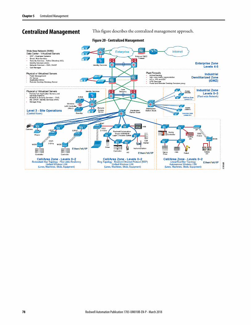
Chapter 5 Centralized Management
Centralized Management This figure describes the centralized management approach.
Figure 20 - Centralized Management
78 Rockwell Automation Publication 1783-UM010B-EN-P - March 2018
Chapter 6
Hardware Bypass
The Stratix 5950 security appliance has hardware bypass relay support between data port pairs 1-2 (copper/fiber) and 3-4 (on copper only). There are two instances where a bypass can be triggered.
• Power failure of the system• The bypass mode is enabled manually through CLI command
Power Failure of the System When power failure happens, the system hard-wires the data ports if you have configured it to do so. All traffic can pass from internal port to external port and vice versa freely. When power is restored, the system software monitors the boot-up progress and only disables the bypass when the system is ready (Firewall and FirePOWER are ready to process packets). An event can be sent out to the management system to indicate the bypass status after power is restored.
Enable the Hardware Bypass by Using CLI Commands
Once you issue a command, the system enables bypass immediately and traffic stops being received by ASA from the paired ports and all Firewall/VPN. The IPS function does not take effect until you issue commands to disable bypass. A critical event is sent to the management system to indicate that no protection is provided by the system.
The enable sfr boot delay feature default is set to on, so the system disables the bypass when both ASA and SFR modules are ready to process packets, after the system boots.
When power is restored, if you want to continue in bypass mode, the system stays in bypass mode if you specifically have it configured to do so. All of the traffic can pass from internal port to external port and vice versa until you manually disable the bypass. An event/trap is sent to the management system to indicate the system still continues bypass after power is restored.
Pairing is restricted by the hardware on Stratix 5950 security appliance to ports 1 & 2 or ports 3 & 4. Port 1 cannot be paired with 3, invalid pairs are (1,3) / (1,4) / (2,3) / (2,4). Valid pairs are (1,2) and (3,4) only.
ASA has CLI commands to allow the following: • Allow user to configure bypass behavior when power fails or power up
conditions• Allow user to enable/disable bypass manually (immediately) • Allow user to check bypass settings and status by show commands
Rockwell Automation Publication 1783-UM010B-EN-P - March 2018 79

Chapter 6 Hardware Bypass
Default State of the Hardware Bypass
The default hardware bypass feature is enabled.
ASA CLI Commands for Hardware Bypass
The following ASA CLI commands have been added to support the hardware bypass feature.
show hardware-bypass
This CLI command displays the status of the bypass on particular port set. The status details the state of the relays on power fail and sticky as well.
CLI shows:
Gigabitethernet 1/1-1/2
-------------------------------
L1-bypass port12 is enable/disable
L1-bypass port12 on power fail is enable/disable
L1-bypass port12 on power up is enable/disable
Gigabitethernet 1/3-1/4
-------------------------------
L1-bypass port34 is enable/disable
L1-bypass port34 on power fail is enable/disable
L1-bypass port34 on power up is enable/disable
[no] hardware-bypass gigabitethernet {1/1-1/2|1/3-1/4} [sticky]
This CLI command is used to enable or disable the bypass mode when power fails and sticky mode. Power failure events can be triggered by a drop in the input 12V supply bellow a lower limit.
[no] hardware-bypass manual gigabitethernet {1/1-1/2|1/3-1/4}
This CLI command is used to control the bypass. Means to enable or disable the bypass mode when power is up and running.
80 Rockwell Automation Publication 1783-UM010B-EN-P - March 2018
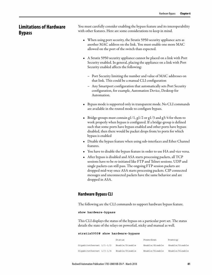
Hardware Bypass Chapter 6
Limitations of Hardware Bypass
You must carefully consider enabling the bypass feature and its interoperability with other features. Here are some considerations to keep in mind.
• When using port security, the Stratix 5950 security appliance acts as another MAC address on the link. You must enable one more MAC allowed on the port of the switch than expected.
• A Stratix 5950 security appliance cannot be placed on a link with Port Security enabled. In general, placing the appliance on a link with Port Security enabled affects the following:
– Port Security limiting the number and value of MAC addresses on that link. This could be a manual CLI configuration
– Any Smartport configuration that automatically sets Port Security configuration, for example, Automation Device, Desktop for Automation.
• Bypass mode is supported only in transparent mode. No CLI commands are available in the routed mode to configure bypass.
• Bridge-groups must contain g1/1, g1/2 or g1/3 and g3/4 for them to work properly when bypass is configured. If a bridge-group is defined such that some ports have bypass enabled and other ports have bypass disabled, then there would be packet drops from/to ports for which bypass is enabled
• Disable the bypass feature when using sub-interfaces and Ether Channel features.
• You have to disable the bypass feature in order to use HA and vice versa.• After bypass is disabled and ASA starts processing packets, all TCP
sessions have to be re-initiated like FTP and Telnet sessions. UDP and single packets can still pass. The ongoing FTP session packets are dropped mid-way once ASA starts processing packets. CIP connected messages and unconnected packets have the same behavior and are dropped in ASA.
Hardware Bypass CLI
The following are the CLI commands to support hardware bypass feature.
show hardware-bypass
This CLI displays the status of the bypass on a particular port set. The status details the state of the relays on powerfail, sticky and manual as well.
stratix5950# show hardware-bypass
Status Powerdown Powerup
Gigabitethernet 1/1-1/2 Enable/Disable Enable/disable Enable/Disable
Gigabitethernet 1/3-1/4 Enable/Disable Enable/Disable Enable/Disable
Rockwell Automation Publication 1783-UM010B-EN-P - March 2018 81

Chapter 6 Hardware Bypass
[no] hardware-bypass gigabitethernet {1/1-1/2|1/3-1/4} [sticky]
This CLI command is used to enable or disable the bypass mode during power down and power up.
Hardware Bypass Behavior During Power Down
To enable hardware bypass mode when power is lost to the appliance the following CLI is used.
stratix5950# conf t
stratix5950(config) #hardware-bypass gigabitethernet 1/1-1/2
To disable hardware bypass mode when power is lost and power up to the appliance the following CLI is used.
stratix5950# conf t
stratix5950(config) #no hardware-bypass gigabitethernet 1/1-1/2
"Hardware Bypass Behavior During Power Up
When hardware bypass is enabled with the power up option, traffic continues to flow on the bypass port pair even after the system boots up. To enable bypass on power up, we should also enable for power fail because the hardware supports power up along with power fail option. The option of power up only is not supported in the hardware.
To enable hardware bypass mode with power down and power up option the following CLI is used.
stratix5950 # conf t
stratix5950(config)#hardware-bypass gigabitethernet 1/1-1/2 sticky
This would disable both power up and power down for ports 1 and 2. The following CLI is used:
stratix5950(config)#no hardware-bypass gigabitethernet 1/1-1/2
[no] hardware-bypass manual gigabitethernet {1/1-1/2|1/3-1/4}
This CLI command is used to enable/disable the bypass feature when the appliance is up and running. This does not depend on the power fail or power up option discussed in earlier sections.
82 Rockwell Automation Publication 1783-UM010B-EN-P - March 2018
Hardware Bypass Chapter 6
To enable hardware bypass mode with the manual option the following CLI is used.
stratix5950# hardware-bypass manual gigabitethernet 1/1-1/2
When hardware bypass is disabled with the manual option, the traffic stops on the bypass port pair immediately and flow through physical interfaces.
To disable hardware bypass mode with the manual option the following CLI is used.
stratix5950# no hardware-bypass manual gigabitethernet 1/1-1/2
"[no] hardware-bypass boot-delay module sfr
This CLI command is used to enable/disable bypass operation delay based on SFR booting status. If it is turned on, the bypass only turns off if SFR module is full up. If it is not turned on, the bypass will be turned off once ASA module is ready. Of course if bypass is not enabled, this command will not have any impact.
For a listing of Cisco documentation, see Additional Resources on page 8.
Rockwell Automation Publication 1783-UM010B-EN-P - March 2018 83

Chapter 6 Hardware Bypass
Notes:
84 Rockwell Automation Publication 1783-UM010B-EN-P - March 2018

Chapter 7
CIP Inspection
CIP Preprocessor The ASA FirePOWER module has a software component in addition to the Network Analysis Policy rules engine called a preprocessor. The preprocessor is responsible to handle the interpretation of the packet before being handled by the rules engine. The IFW has a CIP preprocessor that is capable of interpreting the CIP protocol which allows the system administrator to author policy rules related to the CIP protocol actions.
Common Industrial Protocol (CIP) is an open protocol that encompasses a comprehensive suite of messages and services for industrial automation applications. CIP is used to communicate to ControlLogix processors and I/O subsystems for control, process control, safety, motion control, real time information and network management. The IFW with the CIP preprocessor has the ability to inspect a packet that contains the CIP protocol and determine to permit or deny the traffic based on the preconfigure policy rules.
Two types of CIP DPI rule categories have been added to the IFW:• CIP Generic - related to the open CIP standard• Rockwell Automation specific CIP - CIP protocol extensions specific to
Rockwell Automation products
The CIP protocol has a generic set of commands that are defined by the CIP open standards. The IFW has the ability to define security policies as they relate to the CIP open standard. The list of supported CIP generic rules are:
IMPORTANT In order for any CIP Access Control Policy or CIP Intrusion Policy to work properly, the Network Analysis Policy must be properly configured in order to inspect CIP traffic. See the relevant section in Configure the Security Appliance.
Table 6 - CIP Generic Rules
CIP Generic Rule Description
CIP Admin ODVA-specified commands that change the state of a device.
CIP Infrastructure ODVA-specified commands that are core functions. For example, Setting up sessions and connections.
CIP Malformed Malformed data according to specification.
CIP Read ODVA-specified commands that read data from a device.
CIP Unknown CIP command was unable to be categorized to any other CIP application.
CIP Write ODVA-specified commands that write data into a device.
Rockwell Automation Publication 1783-UM010B-EN-P - March 2018 85
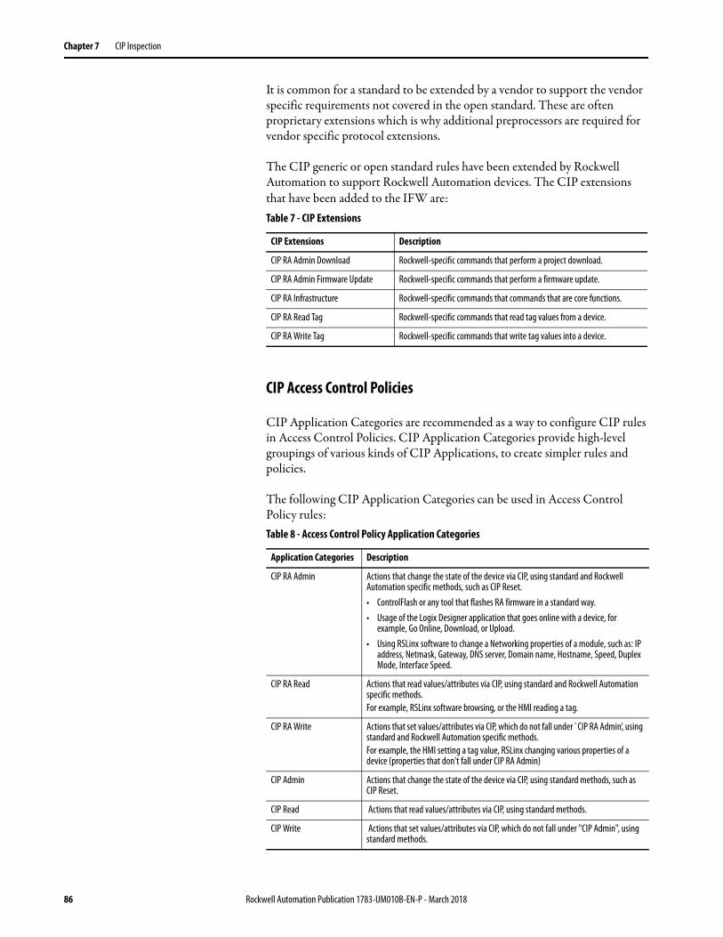
Chapter 7 CIP Inspection
It is common for a standard to be extended by a vendor to support the vendor specific requirements not covered in the open standard. These are often proprietary extensions which is why additional preprocessors are required for vendor specific protocol extensions.
The CIP generic or open standard rules have been extended by Rockwell Automation to support Rockwell Automation devices. The CIP extensions that have been added to the IFW are:
CIP Access Control Policies
CIP Application Categories are recommended as a way to configure CIP rules in Access Control Policies. CIP Application Categories provide high-level groupings of various kinds of CIP Applications, to create simpler rules and policies.
The following CIP Application Categories can be used in Access Control Policy rules:
Table 7 - CIP Extensions
CIP Extensions Description
CIP RA Admin Download Rockwell-specific commands that perform a project download.
CIP RA Admin Firmware Update Rockwell-specific commands that perform a firmware update.
CIP RA Infrastructure Rockwell-specific commands that commands that are core functions.
CIP RA Read Tag Rockwell-specific commands that read tag values from a device.
CIP RA Write Tag Rockwell-specific commands that write tag values into a device.
Table 8 - Access Control Policy Application Categories
Application Categories Description
CIP RA Admin Actions that change the state of the device via CIP, using standard and Rockwell Automation specific methods, such as CIP Reset.• ControlFlash or any tool that flashes RA firmware in a standard way.• Usage of the Logix Designer application that goes online with a device, for
example, Go Online, Download, or Upload.• Using RSLinx software to change a Networking properties of a module, such as: IP
address, Netmask, Gateway, DNS server, Domain name, Hostname, Speed, Duplex Mode, Interface Speed.
CIP RA Read Actions that read values/attributes via CIP, using standard and Rockwell Automation specific methods.For example, RSLinx software browsing, or the HMI reading a tag.
CIP RA Write Actions that set values/attributes via CIP, which do not fall under ̀ CIP RA Admin’, using standard and Rockwell Automation specific methods.For example, the HMI setting a tag value, RSLinx changing various properties of a device (properties that don't fall under CIP RA Admin)
CIP Admin Actions that change the state of the device via CIP, using standard methods, such as CIP Reset.
CIP Read Actions that read values/attributes via CIP, using standard methods.
CIP Write Actions that set values/attributes via CIP, which do not fall under "CIP Admin", using standard methods.
86 Rockwell Automation Publication 1783-UM010B-EN-P - March 2018
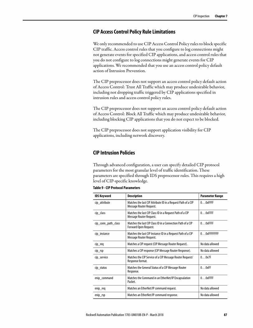
CIP Inspection Chapter 7
CIP Access Control Policy Rule Limitations
We only recommended to use CIP Access Control Policy rules to block specific CIP traffic. Access control rules that you configure to log connections might not generate events for specified CIP applications, and access control rules that you do not configure to log connections might generate events for CIP applications. We recommended that you use an access control policy default action of Intrusion Prevention.
The CIP preprocessor does not support an access control policy default action of Access Control: Trust All Traffic which may produce undesirable behavior, including not dropping traffic triggered by CIP applications specified in intrusion rules and access control policy rules.
The CIP preprocessor does not support an access control policy default action of Access Control: Block All Traffic which may produce undesirable behavior, including blocking CIP applications that you do not expect to be blocked.
The CIP preprocessor does not support application visibility for CIP applications, including network discovery.
CIP Intrusion Policies
Through advanced configuration, a user can specify detailed CIP protocol parameters for the most granular level of traffic identification. These parameters are specified through IDS preprocessor rules. This requires a high level of CIP-specific knowledge.Table 9 - CIP Protocol Parameters
IDS Keyword Description Parameter Range
cip_attribute Matches the last CIP Attribute ID in a Request Path of a CIP Message Router Request.
0…0xFFFF
cip_class Matches the last CIP Class ID in a Request Path of a CIP Message Router Request.
0…0xFFFF
cip_conn_path_class Matches the last CIP Class ID in a Connection Path of a CIP Forward Open Request.
0…0xFFFF
cip_instance Matches the last CIP Instance ID in a Request Path of a CIP Message Router Request.
0…0xFFFFFFFF
cip_req Matches a CIP request (CIP Message Router Request). No data allowed
cip_rsp Matches a CIP response (CIP Message Router Response). No data allowed
cip_service Matches the CIP Service of a CIP Message Router Request/Response format.
0…0x7F
cip_status Matches the General Status of a CIP Message Router Response.
0…0xFF
enip_command Matches the Command in an EtherNet/IP Encapsulation Packet.
0…0xFFFF
enip_req Matches an EtherNet/IP command request. No data allowed
enip_rsp Matches an EtherNet/IP command response. No data allowed
Rockwell Automation Publication 1783-UM010B-EN-P - March 2018 87
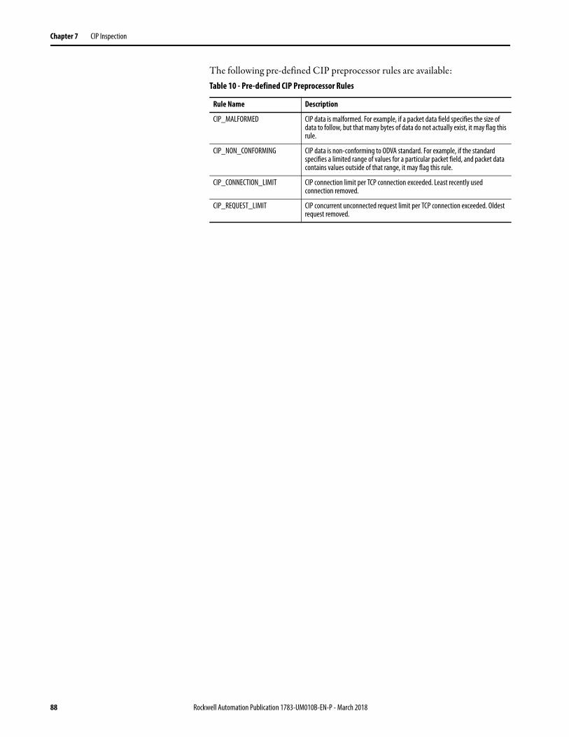
Chapter 7 CIP Inspection
The following pre-defined CIP preprocessor rules are available:Table 10 - Pre-defined CIP Preprocessor Rules
Rule Name Description
CIP_MALFORMED CIP data is malformed. For example, if a packet data field specifies the size of data to follow, but that many bytes of data do not actually exist, it may flag this rule.
CIP_NON_CONFORMING CIP data is non-conforming to ODVA standard. For example, if the standard specifies a limited range of values for a particular packet field, and packet data contains values outside of that range, it may flag this rule.
CIP_CONNECTION_LIMIT CIP connection limit per TCP connection exceeded. Least recently used connection removed.
CIP_REQUEST_LIMIT CIP concurrent unconnected request limit per TCP connection exceeded. Oldest request removed.
88 Rockwell Automation Publication 1783-UM010B-EN-P - March 2018

Chapter 8
Firewall Modes
ASA software provides the firewall features such as ACL, NAT, VPN and overall system and platform management. FirePOWER software provides the Next Generation IPS features, Application Control, Network Discovery, and Network AMP functionality.
The ASA runs in two different firewall modes:• Routed • Transparent
In routed mode, the ASA is considered to be a router hop in the network.
In transparent mode, the ASA acts like a ‘bump in the wire,’ or a ‘stealth firewall,’ and is not considered a router hop. The ASA connects to the same network on its inside and outside interfaces.
FirePOWER module can operate in two modes: inline mode and passive mode. The following figures provide overview of traffic flow in these two modes.
Figure 21 - Traffic Flow under Inline Mode
Rockwell Automation Publication 1783-UM010B-EN-P - March 2018 89

Chapter 8 Firewall Modes
Figure 22 - Traffic Flow under Passive (Monitor Only) Mode
The Stratix 5950 security appliance runs with these defaults: • ASA running in Transparent Mode. • SFR configured to be inline Passive mode. with No Drop Actions. Not
in SPAN/TAP/Passive Mode)
Industrial Firewall Deployment Considerations
The IFW can be deployed in a variety of modes, depending on the level of desired policy enforcement and risk tolerance. It can be placed in an inline or passive location in the network. When located inline, the IFW is inserted into the network segment and can operate in two modes: transparent or routed. When in a passive location, the IFW is separate from the network segment and only receives a copy of the traffic. The following sections provide details and considerations for each supported deployment mode of the IFW.
Inline Transparent Mode
The IFW operates in transparent mode by default. In transparent mode, the IFW acts like a ‘bump in the wire,’ and is not considered a router hop (connects to the same network on its inside and outside interfaces). There can be two variations of this deployment, as described below:
TIP Only use the Smartport `multiport automation device’ for any inline installs.
90 Rockwell Automation Publication 1783-UM010B-EN-P - March 2018

Firewall Modes Chapter 8
In an inline deployment, the actual traffic is sent to the IFW FirePOWER module, and the module's policy affects what happens to the traffic. After dropping undesired traffic and taking any other actions applied by policy, the traffic is returned to the Firewall for further processing.
In inline transparent mode, traffic goes through the firewall checks before being forwarded to the FirePOWER module. The module blocks traffic that is not allowed for a certain application. All other traffic is forwarded through the firewall.
Figure 23 shows the traffic flow when using the IFW in inline transparent mode.
Figure 23 - IFW Traffic Flow for Inline Transparent Mode
As shown in the figure, traffic flows through the IFW as follows:
1. Traffic enters the IFW.
2. Firewall policies are applied.
3. Traffic is sent to the FirePOWER module.
4. The FirePOWER module applies its security policy to the traffic, and takes appropriate actions.
5. Valid traffic is sent back to the firewall; the FirePOWER module might block some traffic according to its security policy.
6. Traffic exits the IFW.
Rockwell Automation Publication 1783-UM010B-EN-P - March 2018 91

Chapter 8 Firewall Modes
Inline Transparent Monitor-only Mode
In an inline monitor-only deployment, a copy of the traffic is sent to the IFW FirePOWER module, but it is not returned to the firewall. Inline monitor-only mode lets you see what the IFW FirePOWER module would have done to traffic, and lets you evaluate the content of the traffic, without impacting the network. However, in this mode, the Firewall does apply its policies to the traffic, so traffic can be dropped due to access rules, TCP normalization, and so forth.
Inline transparent monitor-only mode sends a duplicate stream of traffic to the IFW FirePOWER module for monitoring purposes only. The module applies the security policy to the traffic and logs what it would have done if it were operating in inline transparent mode; for example, traffic might be marked ‘would have dropped’ in events. You can use this information for traffic analysis and to help you decide if inline transparent mode is desirable.
Figure 24 shows the traffic flow when using the IFW in inline transparent monitor-only mode.
Figure 24 - IFW Traffic Flow for Inline Transparent Monitor-only Mode
As shown in the figure, traffic flows through the IFW as follows:
1. Traffic enters the IFW.
2. Firewall policies are applied.
3. Copied traffic is sent to the FirePOWER module.
4. The FirePOWER module applies its security policy to the traffic, and logs events only.
5. Traffic exits the IFW.
TIP You cannot configure both inline monitor-only mode and normal inline mode at the same time on the ASA. Only one type of security policy is allowed.
92 Rockwell Automation Publication 1783-UM010B-EN-P - March 2018

Firewall Modes Chapter 8
Inline Routed Mode In routed mode, the ASA is considered to be a router hop in the network.• Routed mode operates in layer 3 router mode. • Each interface has IP addresses assigned and other typical layer 3
attributes are assigned. • With two subnets active, CAN'T put the box into bypass mode.• Only Active/Standby Mode - No data traffic in link• Remote access to ISA directly.• For routed mode, the following types of traffic are allowed through by
default:– Unicast IPv4 and IPv6 traffic from a higher security interface to a
lower security interface.• Broadcast and multicast traffic is blocked even if you allow it in an access
rule, including unsupported dynamic routing protocols and DHCP (unless you configure DHCP relay).
Passive Monitor-only Mode If you want to prevent any possibility of the IFW impacting traffic, you can configure a traffic-forwarding interface and connect it to a SPAN port on a switch. In this mode, all traffic is sent directly to the IFW FirePOWER module without firewall processing. The traffic is ‘black holed,’ in that nothing is returned from the module, nor does the IFW send the traffic out any interface.
In passive monitor-only mode, the module applies the security policy to the traffic and lets you know what it would have done if it were operating in inline transparent mode; for example, traffic might be marked ‘would have dropped’ in events.
Figure 25 - IFW Traffic Flow for Passive Monitor-only Modeshows the traffic flow when using the IFW in passive monitor-only mode.
As shown in the figure, traffic flows through the IFW as follows:
1. Traffic enters the IFW on the traffic-forwarding interface.
2. All traffic is sent directly to the FirePOWER module.
3. The FirePOWER module applies its security policy to the traffic, and logs events only.
Rockwell Automation Publication 1783-UM010B-EN-P - March 2018 93
Chapter 8 Firewall Modes
Deployment Recommendations
Placement and deployment of the IFW depends on the desired function of the device in the industrial network. When you place the IFW inline with traffic flow, you can monitor the traffic and/or take desired actions, for example blocking. When you place the IFW outside of the traffic flow, you can only monitor the traffic.
Regardless of where the IFW is placed, Cisco and Rockwell Automation recommend configuring the device in monitor-only (IDS) mode during the initial deployment stages. This strategy allows for applications, endpoints, and other communication data to be monitored on the network over a time. IPS policies can be crafted over time that can have the desired effect on targeted traffic without inadvertently affecting other traffic. Once the network traffic has been characterized and the policies have been tested, an IFW deployed inline can be placed into its normal (IPS) mode, helps protect the network. If the risk of inadvertent effects on network traffic outweighs the benefits of IPS for a particular deployment, the IFW can be placed as a passive listener. However, the IFW will have to be physically relocated to be inline with the network segment if an IPS function is desired in the future.
When placed inline, the IFW can be deployed in transparent or routed mode. Cisco and Rockwell Automation generally recommend deploying the IFW in transparent mode (default) unless routing functionality is needed.
In summary, the deployment recommendations for the IFW are as follows:
• Inline transparent mode - Deployments where the ability to help protect the network is more important than traffic affected by potential ‘false positives’. Always place the IFW in monitor-only mode during the initial deployment, then transition to full IPS mode during a maintenance window.
• Inline routed mode - Same as transparent mode, but deployments where routing functionality is also required.
• Passive monitor-only mode - Deployments where uninterrupted connectivity is more important than active network protection. The IFW remains in monitor-only mode with no possibility of running in full IPS mode unless it is moved to be inline in the network segment.
94 Rockwell Automation Publication 1783-UM010B-EN-P - March 2018
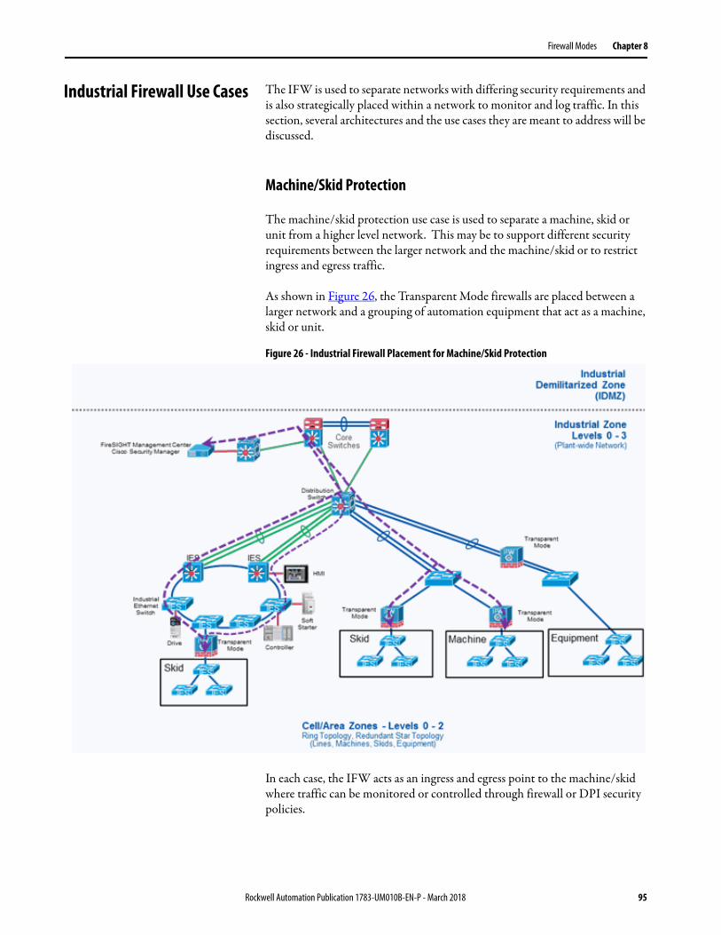
Firewall Modes Chapter 8
Industrial Firewall Use Cases The IFW is used to separate networks with differing security requirements and is also strategically placed within a network to monitor and log traffic. In this section, several architectures and the use cases they are meant to address will be discussed.
Machine/Skid Protection
The machine/skid protection use case is used to separate a machine, skid or unit from a higher level network. This may be to support different security requirements between the larger network and the machine/skid or to restrict ingress and egress traffic.
As shown in Figure 26, the Transparent Mode firewalls are placed between a larger network and a grouping of automation equipment that act as a machine, skid or unit.
Figure 26 - Industrial Firewall Placement for Machine/Skid Protection
In each case, the IFW acts as an ingress and egress point to the machine/skid where traffic can be monitored or controlled through firewall or DPI security policies.
Rockwell Automation Publication 1783-UM010B-EN-P - March 2018 95
Chapter 8 Firewall Modes
Considerations
Before implementing the IFW in a machine/skid protection architecture, it is recommended that the designer understand and document:
• Ingress and egress traffic source and destination host communications. For example, IP Addresses of controllers, HMI, engineering workstations and all communications that enter or leave the machine / skid must be known so firewall and DPI security policies can be configured.
• Ingress and egress traffic source and destination protocols must be known to configure the firewall and DPI rules.
• Ingress and egress traffic volume.
• Redundancy and availability requirements. For example, when considering high availability, one must consider the security considerations while in hardware bypass mode.
96 Rockwell Automation Publication 1783-UM010B-EN-P - March 2018
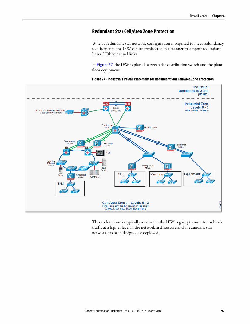
Firewall Modes Chapter 8
Redundant Star Cell/Area Zone Protection
When a redundant star network configuration is required to meet redundancy requirements, the IFW can be architected in a manner to support redundant Layer 2 Etherchannel links.
In Figure 27, the IFW is placed between the distribution switch and the plant floor equipment.
Figure 27 - Industrial Firewall Placement for Redundant Star Cell/Area Zone Protection
This architecture is typically used when the IFW is going to monitor or block traffic at a higher level in the network architecture and a redundant star network has been designed or deployed.
Rockwell Automation Publication 1783-UM010B-EN-P - March 2018 97
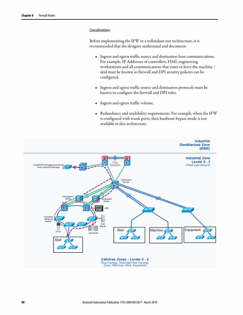
Chapter 8 Firewall Modes
Considerations
Before implementing the IFW in a redundant star architecture, it is recommended that the designer understand and document:
• Ingress and egress traffic source and destination host communications. For example, IP Addresses of controllers, HMI, engineering workstations and all communications that enter or leave the machine / skid must be known so firewall and DPI security policies can be configured.
• Ingress and egress traffic source and destination protocols must be known to configure the firewall and DPI rules.
• Ingress and egress traffic volume.
• Redundancy and availability requirements. For example, when the IFW is configured with trunk ports, then hardware bypass mode is not available in this architecture.
98 Rockwell Automation Publication 1783-UM010B-EN-P - March 2018
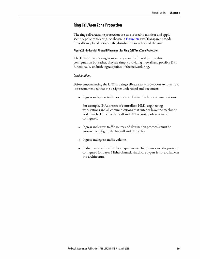
Firewall Modes Chapter 8
Ring Cell/Area Zone Protection
The ring cell/area zone protection use case is used to monitor and apply security policies to a ring. As shown in Figure 28, two Transparent Mode firewalls are placed between the distribution switches and the ring.
Figure 28 - Industrial Firewall Placement for Ring Cell/Area Zone Protection
The IFWs are not acting as an active / standby firewall pair in this configuration but rather, they are simply providing firewall and possibly DPI functionality on both ingress points of the network ring.
Considerations
Before implementing the IFW in a ring cell/area zone protection architecture, it is recommended that the designer understand and document:
• Ingress and egress traffic source and destination host communications.
For example, IP Addresses of controllers, HMI, engineering workstations and all communications that enter or leave the machine / skid must be known so firewall and DPI security policies can be configured.
• Ingress and egress traffic source and destination protocols must be known to configure the firewall and DPI rules.
• Ingress and egress traffic volume.
• Redundancy and availability requirements. In this use case, the ports are configured for Layer 3 Etherchannel. Hardware bypass is not available in this architecture.
Rockwell Automation Publication 1783-UM010B-EN-P - March 2018 99
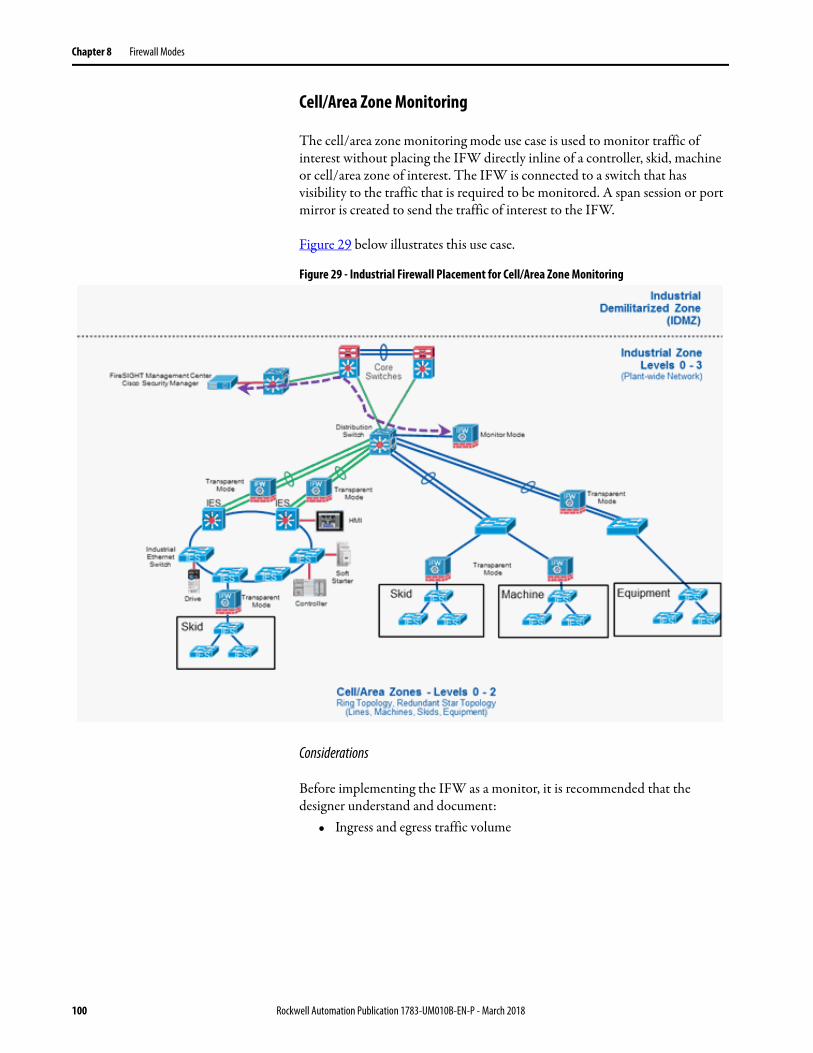
Chapter 8 Firewall Modes
Cell/Area Zone Monitoring
The cell/area zone monitoring mode use case is used to monitor traffic of interest without placing the IFW directly inline of a controller, skid, machine or cell/area zone of interest. The IFW is connected to a switch that has visibility to the traffic that is required to be monitored. A span session or port mirror is created to send the traffic of interest to the IFW.
Figure 29 below illustrates this use case.
Figure 29 - Industrial Firewall Placement for Cell/Area Zone Monitoring
Considerations
Before implementing the IFW as a monitor, it is recommended that the designer understand and document:
• Ingress and egress traffic volume
100 Rockwell Automation Publication 1783-UM010B-EN-P - March 2018
Chapter 9
Troubleshoot
Obtain the Current Running Software Versions
Gathering the latest information about what software your system is currently running is necessary information for troubleshooting. You will need to provide this information when contacting customer support.
1. ASDM method:
a. Login to ASDM.
b. ASDM -> Home -> Device Dashboard -> Device Information.
c. Record the ASA version.
d. Record the ASDM version.
e. ASDM -> Home -> ASA FirePOWER Status -> Module Information.
f. Record the Software Version.
2. ASA console method. Use this if the ASDM method does not work.
a. Login to ASA console.
b. stratix5950> enable
c. stratix5950# show version
d. Record the version for Cisco Adaptive Security Appliance Software Version.
e. Record the version for Device Manager Version.
f. stratix5950# show module sfr
g. Record the SSM Application Version.
Rockwell Automation Publication 1783-UM010B-EN-P - March 101
Chapter 9 Troubleshoot
Updating ASA/ASDM software
Follow these steps to update the ASA/ASDM software.
1. Obtain the latest ASA and ASDM images from the Rockwell Automation support site.
2. Update ASA and ASDM software using the procedure at:
http://www.cisco.com/c/en/us/td/docs/security/asa/asa96/upgrade/upgrade96.html
(ASDM) Upgrade from Your Local Computer
The Upgrade Software from Local Computer tool lets you upload an image file from your computer to the flash file system to upgrade the ASA.
1. (If there is a configuration migration) In ASDM, back up your existing configuration using the Tools > Backup Configurations tool.
2. In the main ASDM application window, choose Tools > Upgrade Software from Local Computer.
The Upgrade Software dialog box appears.
3. From the Image to Upload drop-down list, choose ASDM.
4. In the Local File Path field, enter the local path to the file on your computer or click Browse Local Files to find the file on your PC.
5. In the Flash File System Path field, enter the path to the flash file system or click Browse Flash to find the directory or file in the flash file system.
6. Click Upload Image. The uploading process might take a few minutes.
7. You are prompted to set this image as the ASDM image. Click Yes.
8. You are reminded to exit ASDM and save the configuration. Click OK. You exit the Upgrade tool. Note: You will save the configuration and reload ASDM after you upgrade the ASA software.
9. Repeat these steps, choosing ASA from the Image to Upload drop-down list. You can also use this procedure to upload other file types.
10. Choose Tools > System Reload to reload the ASA.
A new window appears that asks you to verify the details of the reload.
a. Click the Save the running configuration at the time of reload radio button (the default).
b. Choose a time to reload (for example, Now, the default).c. Click Schedule Reload.
Once the reload is in progress, a Reload Status window appears that indicates that a reload is being performed. An option to exit ASDM is also provided.
11. After the ASA reloads, restart ASDM.under the section ‘(ASDM) Upgrade from Your Local Computer’.
102 Rockwell Automation Publication 1783-UM010B-EN-P - March 2018
Troubleshoot Chapter 9
Reset the Device to Factory Defaults
This procedure is based on the following assumptions and performed with these versions of Cisco software:
The procedures are based on instructions from the Cisco website:
https://www.cisco.com/c/en/us/support/docs/security/asa-firepower-services/118644-configure-firepower-00.html
This procedure does not technically perform a true factory reset, but it installs the same software that was included out-of-box.
Software• ASA: asa962-lfbff-k8.SPA• ASDM: asdm-76267.bin• FirePOWER: Cisco_Network_Sensor_Patch-5.4.1.7-18.sh
Prerequisites
The following are prerequisites that are required to get the same results.• PC supported by ASDM.
For example, Windows 7.
• An FTP server installed.
For example, FileZilla (https://filezilla-project.org/download.php?type=server)
• SFR files to restore with:a. asasfr-sys-5.4.1-213.pkgb. asasfr-5500x-boot-5.4.1-213.imgc. Cisco_Network_Sensor_Patch-5.4.1.2-23.shd. Cisco_Network_Sensor_Patch-5.4.1.4-15.she. Cisco_Network_Sensor_Patch-5.4.1.6-37.sh
• Start FTP server, with asasfr-sys-5.4.1-213.pkg and asasfr-5500x-boot-5.4.1-213.img in the root directory
• Serial cable, DB9-to-RJ45• 2x IP addresses on same network as FTP server:
– ASA IP address– SFR IP address
WARNING: This procedure should only be completed when required and requested by Rockwell Automation Technical Support. This procedure can take at least 10 hours of interactive time to perform.
Rockwell Automation Publication 1783-UM010B-EN-P - March 2018 103
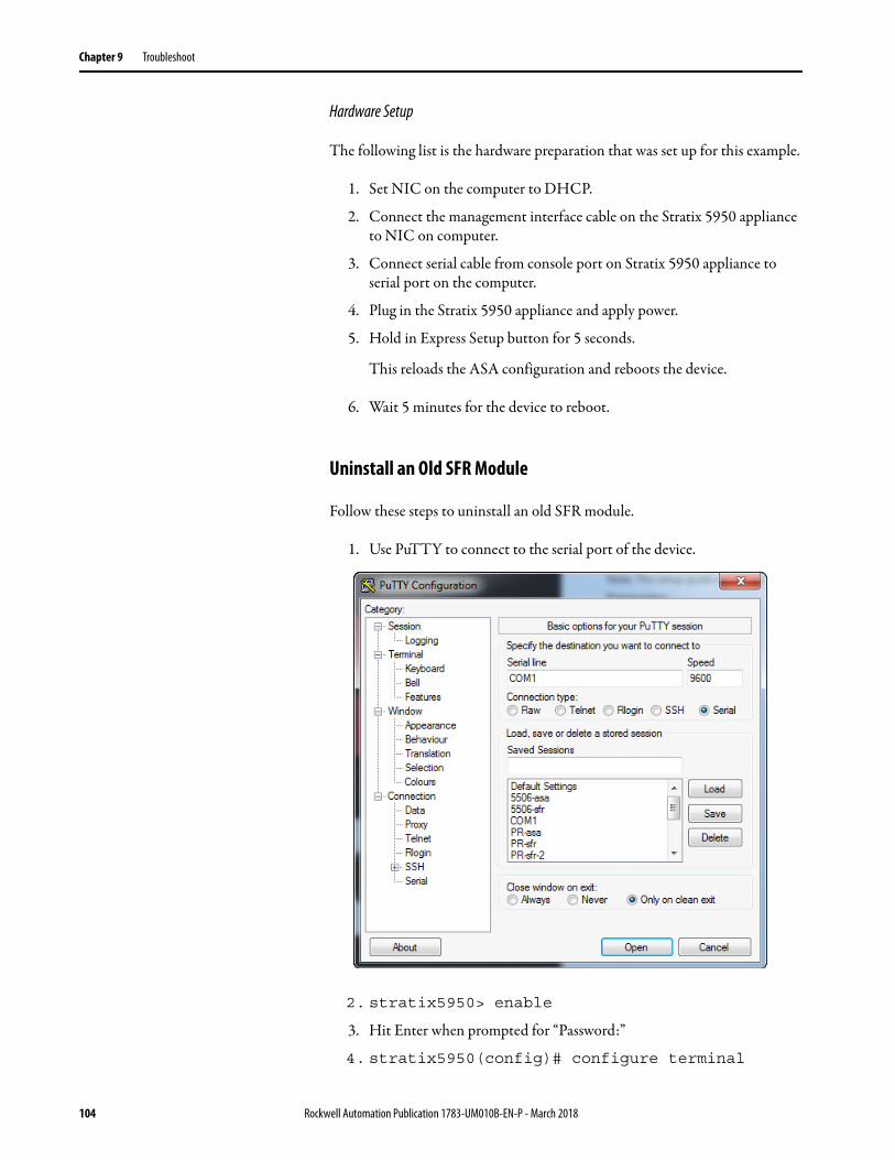
Chapter 9 Troubleshoot
Hardware Setup
The following list is the hardware preparation that was set up for this example.
1. Set NIC on the computer to DHCP.
2. Connect the management interface cable on the Stratix 5950 appliance to NIC on computer.
3. Connect serial cable from console port on Stratix 5950 appliance to serial port on the computer.
4. Plug in the Stratix 5950 appliance and apply power.
5. Hold in Express Setup button for 5 seconds.
This reloads the ASA configuration and reboots the device.
6. Wait 5 minutes for the device to reboot.
Uninstall an Old SFR Module
Follow these steps to uninstall an old SFR module.
1. Use PuTTY to connect to the serial port of the device.
2. stratix5950> enable
3. Hit Enter when prompted for “Password:”
4. stratix5950(config)# configure terminal
104 Rockwell Automation Publication 1783-UM010B-EN-P - March 2018
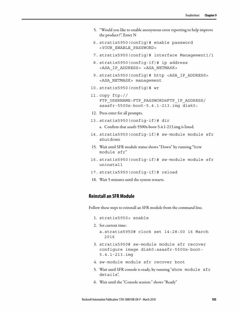
Troubleshoot Chapter 9
5. “Would you like to enable anonymous error reporting to help improve the product?”. Enter N
6. stratix5950(config)# enable password <YOUR_ENABLE_PASSWORD>
7. stratix5950(config)# interface Management1/1
8. stratix5950(config-if)# ip address <ASA_IP_ADDRESS> <ASA_NETMASK>
9. stratix5950(config)# http <ASA_IP_ADDRESS> <ASA_NETMASK> management
10. stratix5950(config)# wr
11. copy ftp://FTP_USERNAME:FTP_PASSWORD@FTP_IP_ADDRESS/asasfr-5500x-boot-5.4.1-213.img disk0:
12. Press enter for all prompts.
13. stratix5950(config-if)# dir
a. Confirm that asasfr-5500x-boot-5.4.1-213.img is listed.
14. stratix5950(config-if)# sw-module module sfr shutdown
15. Wait until SFR module status shows “Down” by running “how module sfr”
16. stratix5950(config-if)# sw-module module sfr uninstall
17. stratix5950(config-if)# reload
18. Wait 5 minutes until the system restarts.
Reinstall an SFR Module
Follow these steps to reinstall an SFR module from the command line.
1. stratix5950> enable
2. Set current time:a.stratix5950# clock set 14:28:00 16 March 2016
3. stratix5950# sw-module module sfr recover configure image disk0:asasfr-5500x-boot-5.4.1-213.img
4. sw-module module sfr recover boot
5. Wait until SFR console is ready, by running "show module sfr details".
6. Wait until the "Console session:" shows "Ready"
Rockwell Automation Publication 1783-UM010B-EN-P - March 2018 105
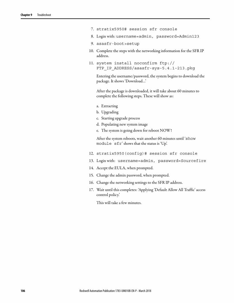
Chapter 9 Troubleshoot
7. stratix5950# session sfr console
8. Login with: username=admin, password=Admin123
9. asasfr-boot>setup
10. Complete the steps with the networking information for the SFR IP address.
11. system install noconfirm ftp://FTP_IP_ADDRESS/asasfr-sys-5.4.1-213.pkg
Entering the username/password, the system begins to download the package. It shows ‘Download…’
After the package is downloaded, it will take about 60 minutes to complete the following steps. These will show as:
a. Extractingb. Upgradingc. Starting upgrade processd. Populating new system imagee. The system is going down for reboot NOW!
After the system reboots, wait another 60 minutes until ‘show module sfr’ shows that the status is ‘Up’.
12. stratix5950(config)# session sfr console
13. Login with: username=admin, password=Sourcefire
14. Accept the EULA, when prompted.
15. Change the admin password, when prompted.
16. Change the networking settings to the SFR IP address.
17. Wait until this completes: ‘Applying 'Default Allow All Traffic' access control policy.’
This will take a few minutes.
106 Rockwell Automation Publication 1783-UM010B-EN-P - March 2018

Troubleshoot Chapter 9
Install the SFR 5.4.1.2 Update
Follow these steps to install the SFR 5.4.1.2 update.
1. Login to ASDM, by going to:
https://ASA_IP_ADDRESS/admin/public/index.html
2. Select Run ASDM.
3. Login with the ASA enable password that you set above.
4. ASDM > Configuration > ASA FirePOWER Configuration > Updates -> Upload Update.
5. Select Cisco_Network_Sensor_Patch-5.4.1.2-23.sh.
6. After the file uploads, install the update.
7. Wait 2 hours.
8. Exit ASDM.
Rockwell Automation Publication 1783-UM010B-EN-P - March 2018 107
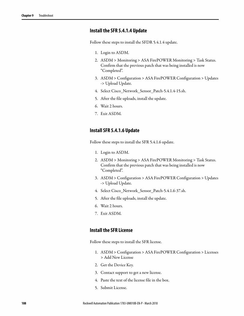
Chapter 9 Troubleshoot
Install the SFR 5.4.1.4 Update
Follow these steps to install the SFDR 5.4.1.4 update.
1. Login to ASDM.
2. ASDM > Monitoring > ASA FirePOWER Monitoring > Task Status. Confirm that the previous patch that was being installed is now “Completed”.
3. ASDM > Configuration > ASA FirePOWER Configuration > Updates -> Upload Update.
4. Select Cisco_Network_Sensor_Patch-5.4.1.4-15.sh.
5. After the file uploads, install the update.
6. Wait 2 hours.
7. Exit ASDM.
Install SFR 5.4.1.6 Update
Follow these steps to install the SFR 5.4.1.6 update.
1. Login to ASDM.
2. ASDM > Monitoring > ASA FirePOWER Monitoring > Task Status. Confirm that the previous patch that was being installed is now “Completed”.
3. ASDM > Configuration > ASA FirePOWER Configuration > Updates -> Upload Update.
4. Select Cisco_Network_Sensor_Patch-5.4.1.6-37.sh.
5. After the file uploads, install the update.
6. Wait 2 hours.
7. Exit ASDM.
Install the SFR License
Follow these steps to install the SFR license.
1. ASDM > Configuration > ASA FirePOWER Configuration > Licenses > Add New License
2. Get the Device Key.
3. Contact support to get a new license.
4. Paste the text of the license file in the box.
5. Submit License.
108 Rockwell Automation Publication 1783-UM010B-EN-P - March 2018
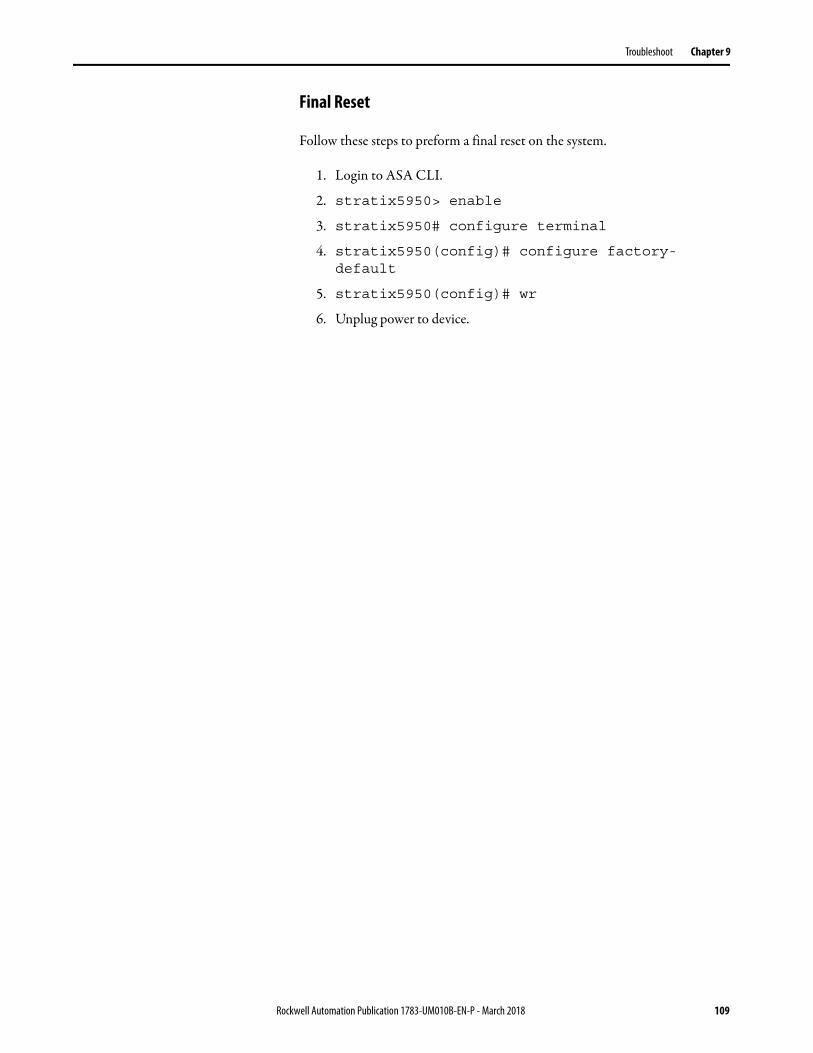
Troubleshoot Chapter 9
Final Reset
Follow these steps to preform a final reset on the system.
1. Login to ASA CLI.
2. stratix5950> enable
3. stratix5950# configure terminal
4. stratix5950(config)# configure factory-default
5. stratix5950(config)# wr
6. Unplug power to device.
Rockwell Automation Publication 1783-UM010B-EN-P - March 2018 109

Chapter 9 Troubleshoot
Notes:
110 Rockwell Automation Publication 1783-UM010B-EN-P - March 2018
Glossary
The following terms and abbreviations are used throughout this manual. For definitions of terms not listed here, refer to the Allen-Bradley Industrial Automation Glossary, publication AG-7.1.
ASA Adapative Security Appliance
ASDM Cisco Device Management software for ASA platform
Bypass Relay Bypass relay is used when there is a loss of power or under software control. Two cases trigger a bypass, a power failure of the system or you enable the bypass through a CLI command.
CIP Common Industrial Protocol
CLI Command Line Interface commands
Clientless SSL Helps ensure secure access to pre-configured network resources on a corporate network using an SSL-enabled web browser.
CPwE architecture Converged Plantwide Ethernet (CPwE) is a collection of tested and validated architectures that are developed by subject matter authorities at Cisco and Rockwell Automation® which follows the Cisco Validated Design (CVD) program.
CSM Version 4.11 The Stratix 5950 security appliance is a joint technology collaboration with Cisco. You can leverage the CSM and FireSIGHT Management Center Cisco software bundles with this device.
CSM: Cisco Security ManagementSystem
The Cisco Security Manager (CSM) provides scalable, centralized management for the firewall component of the IFW.
DHCP Dynamic Host Configuration Protocol
DIN Rail A metal rail of a standard type that is widely used for mounting circuit breakers and industrial control equipment inside equipment racks.
EIP ModStatus The System status indicator shows the power status of the appliance.
FireSIGHT Management CenterVersion 5.4.1.6
The Cisco FireSIGHT Management Center manages the FirePOWER module of the IFW.
Firewall Firewalls are used to separate networks with differing security requirements, such as the Enterprise zone and the Industrial Zone.
Internet Protocol (IP) Internet Protocol Common protocol used in conjunction with Ethernet, commonly used with the Internet. It is the protocol used for forwarding packets on a network.
IP/Sec IPSec is a standard set of protocols that provide data security at the IP packet level.
Rockwell Automation Publication 1783-UM010B-EN-P - March 111
Glossary
Intrusion Prevention System (IPS) IPS is a network security/threat prevention technology that examines network traffic flows to detect and prevent vulnerability exploits.
K9 License A web-based filtering technology that provides automatic updates when you need a robust, real-time solution.
Management Information Base(MIB)
is a database used for managing the entities in a communication network. Most often associated with the Simple Network Management Protocol (SNMP), the term is also used more generically in contexts such as in OSI/ISO Network management model.
Secure Digital (SD) Secure Digital memory card format developed by the SD Card Association (SDA) for use in portable devices.
Simple Network ManagementProtocol (SNMP)
SNMP is an Internet-standard protocol for collecting and organizing information about managed devices on IP networks and for modifying that information to change device behavior.
SSL VPN Allows for the creation of a secure, encrypted connection without requiring specialized software on an end user’s computer.
System On Chip (SoC) A system on a chip or system on chip (SoC or SOC) is an integrated circuit (IC) that integrates all components of a computer or other electronic system into a single chip.
TA License Helps provide increased control and protection during system updates.
Virtual Private Network (VPN) VPN is a virtual version of a secure, physical network.
112 Rockwell Automation Publication 1783-UM010B-EN-P - March 2018
Index
Numerics3DES/AES 9
Aalarm 17, 71ASA 39ASA firewall 9
Bbase license 9bridge-groups 81bypass relay 10, 79
CCentralized management 77centralized management 73, 75CIP inspection 86CIP RA Admin 86CIP RA Read 86CIP RA Write 86CLI commands 17Clientless SSL 9configuration 37configuration mode 38
inline 38span port 38
console 12, 13console cable 38console port 16control policies 86
CIP intrusion 87rule limitations 87
copper 12, 13
DDB9-to-RJ45 38DC Power 12, 13dm-launcher.msi 39dual power supplies 17dual power supply 17
EEIP 12, 13EIP Mod 39EIP ModStatus 71ethernet cable 38Ethernet port 72express setup 12, 13, 14
Ffiber 11FireSIGHT Management Center 73, 77firewall 9
Gground 12, 13
Hhardware bypass 79
limitations 81
IInline Mode 42intrusion prevention 73IPsec 9
Llogs 15
Mmalware 73management 73management port 9, 16memory 15mini-USB 12, 13
NNIC 38
Oout-of-the-box- configuration 37
Ppin-outs 16ports and management 71power failure 79power inputs 71power supply 15, 38power-supply dual 17prerequisites 38PuTTY 38
Rreal time eventing view 63redundant power 10, 15
Rockwell Automation Publication 1783-UM010B-EN-P - March 2018 113
Index
remote dial-in modem 16reset device 103RJ-45 12, 13RSLinx 68rules 60
SSD card 12, 13, 15SPAN Port Mode 42status indicators 71storage 15
Ttemperature 17, 18terminal 15test policy 53test your system 37troubleshoot
reset device 103verify boot fast 103
UUSB 12, 13, 15
114 Rockwell Automation Publication 1783-UM010B-EN-P - March 2018

Publication 1783-UM010B-EN-P - March 2018Supersedes Publication 1783-UM010A-EN-P - October 2016 Copyright © 2018 Rockwell Automation, Inc. All rights reserved. Printed in the U.S.A.
Rockwell Automation SupportUse the following resources to access support information.
Documentation FeedbackYour comments will help us serve your documentation needs better. If you have any suggestions on how to improve this document, complete the How Are We Doing? form at http://literature.rockwellautomation.com/idc/groups/literature/documents/du/ra-du002_-en-e.pdf.
Technical Support Center Knowledgebase Articles, How-to Videos, FAQs, Chat, User Forums, and Product Notification Updates. https://rockwellautomation.custhelp.com/
Local Technical Support Phone Numbers Locate the phone number for your country. http://www.rockwellautomation.com/global/support/get-support-now.page
Direct Dial Codes Find the Direct Dial Code for your product. Use the code to route your call directly to a technical support engineer. http://www.rockwellautomation.com/global/support/direct-dial.page
Literature Library Installation Instructions, Manuals, Brochures, and Technical Data. http://www.rockwellautomation.com/global/literature-library/overview.page
Product Compatibility and Download Center (PCDC)
Get help determining how products interact, check features and capabilities, and find associated firmware. http://www.rockwellautomation.com/global/support/pcdc.page
.
Rockwell Otomasyon Ticaret A.Ş., Kar Plaza İş Merkezi E Blok Kat:6 34752 İçerenköy, İstanbul, Tel: +90 (216) 5698400
Rockwell Automation maintains current product environmental information on its website at http://www.rockwellautomation.com/rockwellautomation/about-us/sustainability-ethics/product-environmental-compliance.page.
Allen-Bradley, Rockwell Software, Rockwell Automation, RSLinx, and Stratix are trademarks of Rockwell Automation, Inc.
Trademarks not belonging to Rockwell Automation are property of their respective companies.