Embed Size (px)
Citation preview

Stratix 5700Switch Configuration
Quick Start

Important User Information
Read this document and the documents listed in the additional resources section about installation, configuration, and operation of this equipment before you install, configure, operate, or maintain this product. Users are required to familiarize themselves with installation and wiring instructions in addition to requirements of all applicable codes, laws, and standards.
Activities including installation, adjustments, putting into service, use, assembly, disassembly, and maintenance are required to be carried out by suitably trained personnel in accordance with applicable code of practice.
If this equipment is used in a manner not specified by the manufacturer, the protection provided by the equipment may be impaired.
In no event will Rockwell Automation, Inc. be responsible or liable for indirect or consequential damages resulting from the use or application of this equipment.
The examples and diagrams in this manual are included solely for illustrative purposes. Because of the many variables and requirements associated with any particular installation, Rockwell Automation, Inc. cannot assume responsibility or liability for actual use based on the examples and diagrams.
No patent liability is assumed by Rockwell Automation, Inc. with respect to use of information, circuits, equipment, or software described in this manual.
Reproduction of the contents of this manual, in whole or in part, without written permission of Rockwell Automation, Inc., is prohibited.
Throughout this manual, when necessary, we use notes to make you aware of safety considerations.
Labels may also be on or inside the equipment to provide specific precautions.
Allen-Bradley, Rockwell Software, and Rockwell Automation are trademarks of Rockwell Automation, Inc.
Trademarks not belonging to Rockwell Automation are property of their respective companies.
WARNING: Identifies information about practices or circumstances that can cause an explosion in a hazardous environment, which may lead to personal injury or death, property damage, or economic loss.
ATTENTION: Identifies information about practices or circumstances that can lead to personal injury or death, property damage, or economic loss. Attentions help you identify a hazard, avoid a hazard, and recognize the consequence.
IMPORTANT Identifies information that is critical for successful application and understanding of the product.
SHOCK HAZARD: Labels may be on or inside the equipment, for example, a drive or motor, to alert people that dangerous voltage may be present.
BURN HAZARD: Labels may be on or inside the equipment, for example, a drive or motor, to alert people that surfaces may reach dangerous temperatures.
ARC FLASH HAZARD: Labels may be on or inside the equipment, for example, a motor control center, to alert people to potential Arc Flash. Arc Flash will cause severe injury or death. Wear proper Personal Protective Equipment (PPE). Follow ALL Regulatory requirements for safe work practices and for Personal Protective Equipment (PPE).
Table of Contents
Preface About This Publication. . . . . . . . . . . . . . . . . . . . . . . . . . . . . . . . . . . . . . . . . . . . . 3Additional Resources . . . . . . . . . . . . . . . . . . . . . . . . . . . . . . . . . . . . . . . . . . . . . . . 3
Set Up the Switch Initially with Express Setup
Before You Begin . . . . . . . . . . . . . . . . . . . . . . . . . . . . . . . . . . . . . . . . . . . . . . . . . . 5What You Need . . . . . . . . . . . . . . . . . . . . . . . . . . . . . . . . . . . . . . . . . . . . . . . . . . . 5Run Express Setup . . . . . . . . . . . . . . . . . . . . . . . . . . . . . . . . . . . . . . . . . . . . . . . . . 6
Assigning the Smartports Using the Device Manager Web Interface (Optional)
Before You Begin . . . . . . . . . . . . . . . . . . . . . . . . . . . . . . . . . . . . . . . . . . . . . . . . 11What You Need . . . . . . . . . . . . . . . . . . . . . . . . . . . . . . . . . . . . . . . . . . . . . . . . . 11Access the Device Manager Web Interface . . . . . . . . . . . . . . . . . . . . . . . . . 12Smartports . . . . . . . . . . . . . . . . . . . . . . . . . . . . . . . . . . . . . . . . . . . . . . . . . . . . . . 13
Configure Smartports . . . . . . . . . . . . . . . . . . . . . . . . . . . . . . . . . . . . . . . . 13Optimize Ports Through Smartports Port Roles . . . . . . . . . . . . . . . . 14
Rockwell Automation Publication IASIMP-QS040A-EN-E - April 2014 1

Table of Contents
Notes:
2 Rockwell Automation Publication IASIMP-QS040A-EN-E - April 2014

Preface
About This Publication
This Quick Start provides examples and procedures for configuring Stratix 5700 switches.
Additional Resources
Use the additional resources listed in this table for more information when using Stratix 5700 switches.
You can view or download publications at http:/www.rockwellautomation.com/literature/. To order paper copies of technical documentation, contact your local Allen-Bradley distributor or Rockwell Automation sales representative.
Resource Description
Stratix 5700 Industrial Ethernet Switch Product Profile, publication ENET-PP005 Overview of features and functionality of Stratix 5700 Switches.
Stratix 5700 Ethernet Managed Switches User Manual, publication 1783-UM004-EN-P Describes the installation, configuration, and troubleshooting of Stratix 5700 Switches.
Stratix Ethernet Switches Specifications, publication 1783-TD001-EN-P Describes the Specification of Stratix Ethernet Switches.
Rockwell Automation Publication IASIMP-QS040A-EN-E - April 2014 3

Preface
Notes:
4 Rockwell Automation Publication IASIMP-QS040A-EN-E - April 2014
Chapter 1
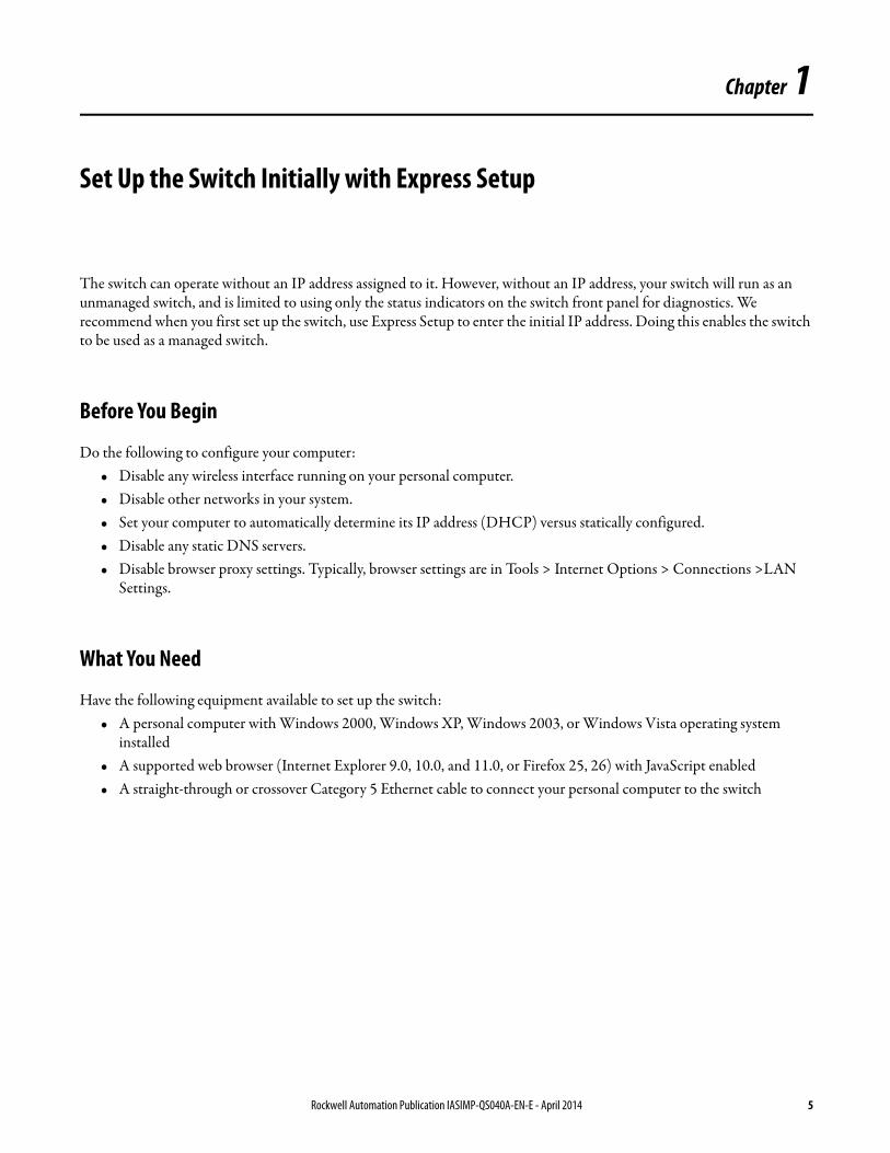
Set Up the Switch Initially with Express Setup
The switch can operate without an IP address assigned to it. However, without an IP address, your switch will run as an unmanaged switch, and is limited to using only the status indicators on the switch front panel for diagnostics. We recommend when you first set up the switch, use Express Setup to enter the initial IP address. Doing this enables the switch to be used as a managed switch.
Before You Begin
Do the following to configure your computer:• Disable any wireless interface running on your personal computer.• Disable other networks in your system.• Set your computer to automatically determine its IP address (DHCP) versus statically configured.• Disable any static DNS servers.• Disable browser proxy settings. Typically, browser settings are in Tools > Internet Options > Connections >LAN
Settings.
What You Need
Have the following equipment available to set up the switch:• A personal computer with Windows 2000, Windows XP, Windows 2003, or Windows Vista operating system
installed• A supported web browser (Internet Explorer 9.0, 10.0, and 11.0, or Firefox 25, 26) with JavaScript enabled• A straight-through or crossover Category 5 Ethernet cable to connect your personal computer to the switch
Rockwell Automation Publication IASIMP-QS040A-EN-E - April 2014 5

Chapter 1 Set Up the Switch Initially with Express Setup
Run Express Setup
To run Express Setup, follow these steps.
1. Make sure that at least one switch Ethernet port is available for Express Setup.
During Express Setup, the switch acts as a DHCP server. If your personal computer has a static IP address, change your personal computer settings before you begin to temporarily use DHCP.
2. Apply power to the switch.
When the switch powers on, it begins its power on sequence. The power on sequence takes approximately 60 seconds to complete.
3. Make sure that the power on sequence has completed by verifying that the EIP Mod and Setup status indicators are flashing green. If the switch fails the power on sequence, the EIP Mod status indicator turns red.
4. Press and release the Express Setup button shown in Figure 1. Wait for a few seconds until the status indicator on one of the unconnected switch ports flashes green.
Figure 1 - Express Setup Button
This button is recessed 16 mm (0.63 in.) behind the front panel. Use a small tool, such as a paper clip, to reach the button.
5. Connect a Category 5 Ethernet cable from the flashing switch port to the Ethernet port on your personal computer.
The port status indicators on your personal computer and on the switch both flash while the switch configures the connection.
IMPORTANT Do not use the console port for Express Setup.
TIP If you wait too long to connect the cable, the Setup status indicator turns off.
6 Rockwell Automation Publication IASIMP-QS040A-EN-E - April 2014

Set Up the Switch Initially with Express Setup Chapter 1
6. While the Setup status indicator flashes green, start an Internet browser session on the personal computer and navigate to http://169.254.0.1. If you have a home page configured, the switch configuration loads instead of your normal home page. The switch prompts you for the default switch username and password.
7. Enter the default switch password: switch. The default user name is admin.
8. If the Express setup window does not appear, do the following:• Enter the URL of a well-known website in your browser to be sure the browser is working correctly. Your browser
then automatically redirects to the Express Setup web page.• Verify that any proxy settings or pop-up blockers are disabled on your browser.• Verify that any wireless interface is disabled on your personal computer.
9. Complete the fields shown in Figure 2. To view fields for Common Industrial Protocol (CIP), you must click Advanced Settings (refer to Table 1).
Figure 2 - Express Setup Window
IMPORTANT In some scenarios, the switch requires you to enter the switch password multiple times before it accepts the password.
Rockwell Automation Publication IASIMP-QS040A-EN-E - April 2014 7

Chapter 1 Set Up the Switch Initially with Express Setup
Table 1 - Express Setup Fields
Field Description
Network Settings
Host Name The name of the device.
Management Interface (VLAN ID) The name and ID of the management VLAN through which the switch is managed. Choose an existing VLAN to be the management VLAN.The default ID is 1. The default name for the management VLAN is default. The number can be from 1 ... 1001. Be sure that the switch and your network management station are in the same VLAN. Otherwise, you lose management connectivity to the switch. The management VLAN is the broadcast domain through which management traffic is sent between specific users or devices. It provides broadcast control and security for management traffic that must be limited to a specific group of users, such as the administrators of your network. It also provides secure administrative access to all devices in the network at all times.
IP Assignment Mode The IP Assignment mode determines whether the switch IP Information is manually assigned (static) or is automatically assigned by a Dynamic Host Configuration Protocol (DHCP) server. The default is Static.We recommend that you click Static and manually assign the IP address for the switch. You can then use the same IP address whenever you want to access the Device Manager web interface.
IP Address The IP address and associated subnet mask are unique identifiers for the switch in a network:• The IP address format is a 32-bit numeric address written as four numbers separated by periods. Each number can range
between 0 ... 255.• The subnet mask is the network address that identifies the subnetwork (subnet) to which the switch belongs. Subnets are
used to segment the devices in a network into smaller groups. The default is 255.255.255.0.This field is enabled only if the IP Assignment mode is Static.Make sure that the IP address that you assign to the switch is not being used by another device in your network. The IP address and the default gateway cannot be the same.
Default Gateway (optional) The IP address for the default gateway. A gateway is a router or a dedicated network device that enables the switch to communicate with devices in other networks or subnetworks. The default gateway IP address must be part of the same subnet as the switch IP address. The switch IP address and the default gateway IP address cannot be the same.If all of your devices are in the same network and the default gateway is not used, you do not need to enter an IP address in this field. This field is enabled only if the IP assignment mode is Static.You must specify a default gateway if your network management station and the switch are in different networks or subnetworks. Otherwise, the switch and your network management station cannot communicate with each other.
NTP Server The IP address of the Network Time Protocol (NTP) server. NTP is a networking protocol for clock synchronization between computer systems over packet switched, variable-latency data networks.
User Enter the user name.
Password, Confirm Password The password for the switch can have up to 63 alphanumeric characters, can start with a number, is case-sensitive, and can have embedded spaces. The password cannot be a single digit, it cannot contain a ? or a tab, and it does not allow spaces at the beginning or the end. The default is switch.To complete initial setup, you must change the password from the default password, switch.This password is also used as the Control Industrial Protocol (CIP) security password. We recommend that you provide a password to the switch to secure access to the device manager.
Advanced Settings
CIP VLAN The VLAN on which Common Industrial Protocol (CIP) is enabled. The CIP VLAN can be the same as the management VLAN or you can isolate CIP traffic on another VLAN that is already configured on this device.
IP Address The IP address and subnet mask for the CPI VLAN if the CIP VLAN is different from the management VLAN. The format is a 32-bit numeric address written as four numbers separated by periods. Each number can be from 0...255.Make sure that the IP address that you assign to this device is not being used by another device in your network.
Same As Management VLAN Indicates whether the settings for the CIP VLAN are the same as the management VLAN.
Telnet, CIP and Enable Password (optional), Confirm Password
This is the password used for Telnet and CIP security.
Same As Admin Password Sets the password used for Telnet and CIP security to the same user password specified under Network Settings.
8 Rockwell Automation Publication IASIMP-QS040A-EN-E - April 2014
Set Up the Switch Initially with Express Setup Chapter 1
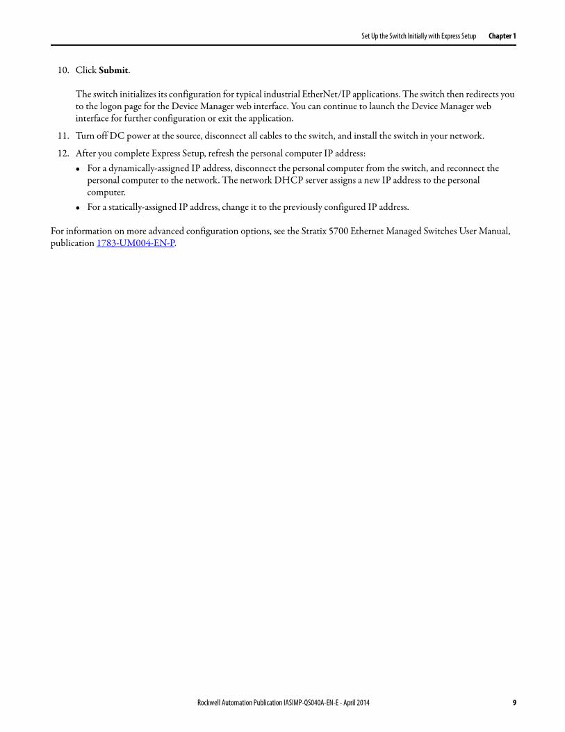
10. Click Submit.
The switch initializes its configuration for typical industrial EtherNet/IP applications. The switch then redirects you to the logon page for the Device Manager web interface. You can continue to launch the Device Manager web interface for further configuration or exit the application.
11. Turn off DC power at the source, disconnect all cables to the switch, and install the switch in your network.
12. After you complete Express Setup, refresh the personal computer IP address:• For a dynamically-assigned IP address, disconnect the personal computer from the switch, and reconnect the
personal computer to the network. The network DHCP server assigns a new IP address to the personal computer.
• For a statically-assigned IP address, change it to the previously configured IP address.
For information on more advanced configuration options, see the Stratix 5700 Ethernet Managed Switches User Manual, publication 1783-UM004-EN-P.
Rockwell Automation Publication IASIMP-QS040A-EN-E - April 2014 9

Chapter 1 Set Up the Switch Initially with Express Setup
Notes:
10 Rockwell Automation Publication IASIMP-QS040A-EN-E - April 2014
Chapter 2
Assigning the Smartports Using the Device Manager Web Interface (Optional)
After you complete Express Setup, you can manage the switch by using the Device Manager Web interface supplied with the switch.
Before You Begin
Complete the steps for the Express Setup in Chapter 1.
What You Need
Have the following equipment available to set up the switch:• A personal computer with Windows 2000, Windows XP, Windows 2003, or Windows Vista operating system
installed• A supported web browser (Internet Explorer 9.0, 10.0, and 11.0, or Firefox 25, 26) with JavaScript enabled• A straight-through or crossover Category 5 Ethernet cable to connect your personal computer to the switch
Rockwell Automation Publication IASIMP-QS040A-EN-E - April 2014 11
Chapter 2 Assigning the Smartports Using the Device Manager Web Interface (Optional)
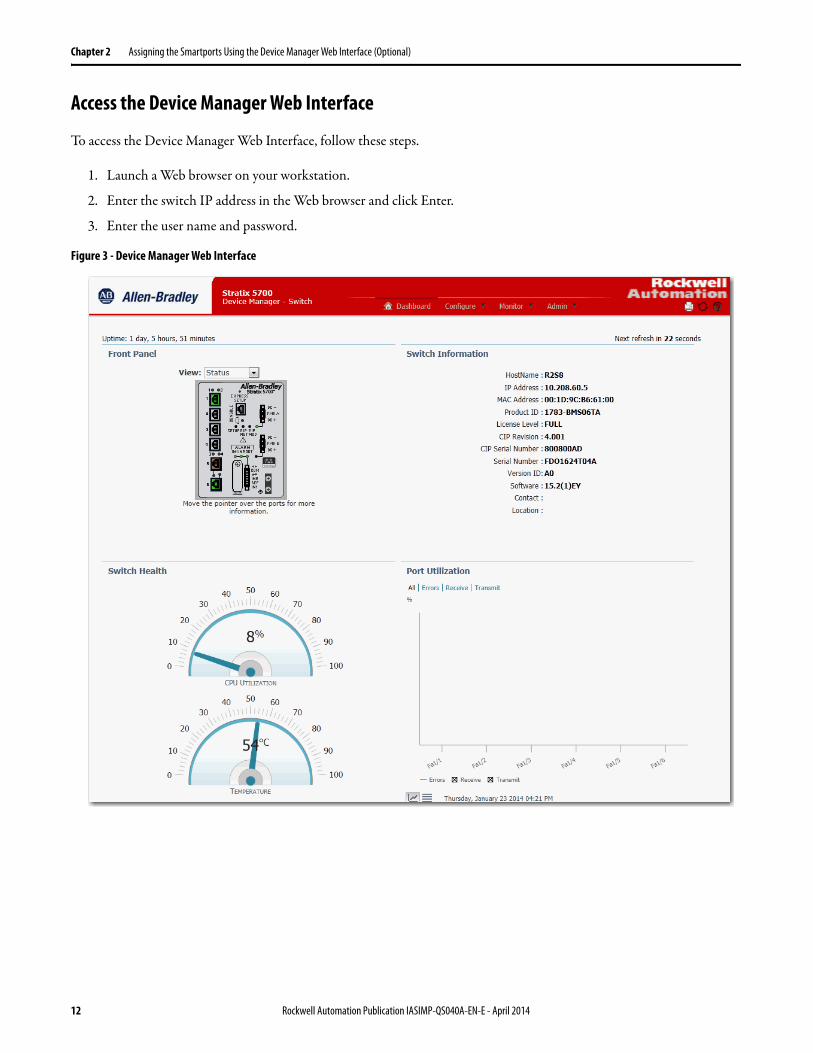
Access the Device Manager Web Interface
To access the Device Manager Web Interface, follow these steps.
1. Launch a Web browser on your workstation.
2. Enter the switch IP address in the Web browser and click Enter.
3. Enter the user name and password.
Figure 3 - Device Manager Web Interface
12 Rockwell Automation Publication IASIMP-QS040A-EN-E - April 2014
Assigning the Smartports Using the Device Manager Web Interface (Optional) Chapter 2
Smartports
Smartports are recommended configurations for the switch ports. These configurations, referred to as port roles, optimize the switch connections and provide security, transmission quality, and reliability for traffic from the switch ports. The port roles also help prevent port misconfigurations.
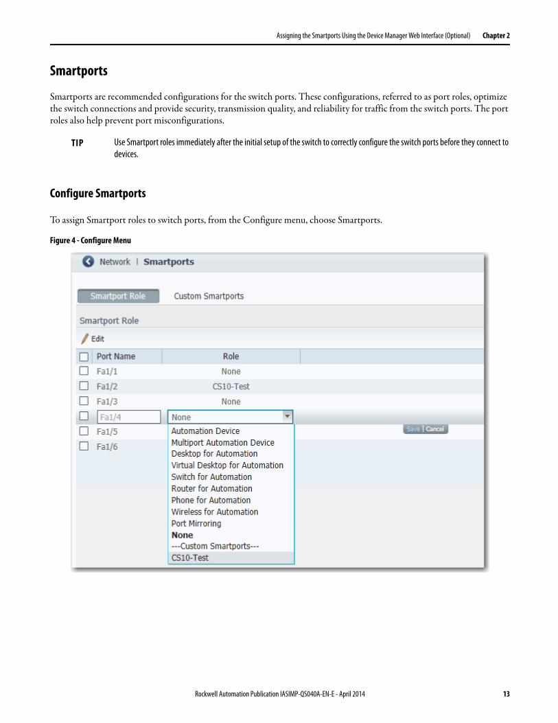
Configure Smartports
To assign Smartport roles to switch ports, from the Configure menu, choose Smartports.
Figure 4 - Configure Menu
TIP Use Smartport roles immediately after the initial setup of the switch to correctly configure the switch ports before they connect to devices.
Rockwell Automation Publication IASIMP-QS040A-EN-E - April 2014 13

Chapter 2 Assigning the Smartports Using the Device Manager Web Interface (Optional)
Follow these guidelines when using Smartport roles:• Before using Smartport roles, decide which switch port is connected to which device type.• Before attaching a device to the port or reconnecting devices that have been moved, verify which Smartport role is
applied to a port.
• When the user attempts to apply a port role to a routed port in the Smartports window, this error message appears:
A port role cannot be configured on a routed port.
To apply a Smartport role, follow this procedure.
1. From the Configure menu, choose Smartports.
2. Select a port.
3. Choose a Smartport role from the pull-down menu in the Role column.
4. Click Save.
Optimize Ports Through Smartports Port Roles
The port roles are based on the type of devices to be connected to the switch ports. For example, the Desktop for Automation port role is specifically for switch ports to be connected to desktop and laptop /computers. Refer to Table 2 for a list of available ports.
IMPORTANT We recommend that you do not change port settings after enabling a Smartport role on a port. Any port setting changes can alter the effectiveness of the Smartport role.
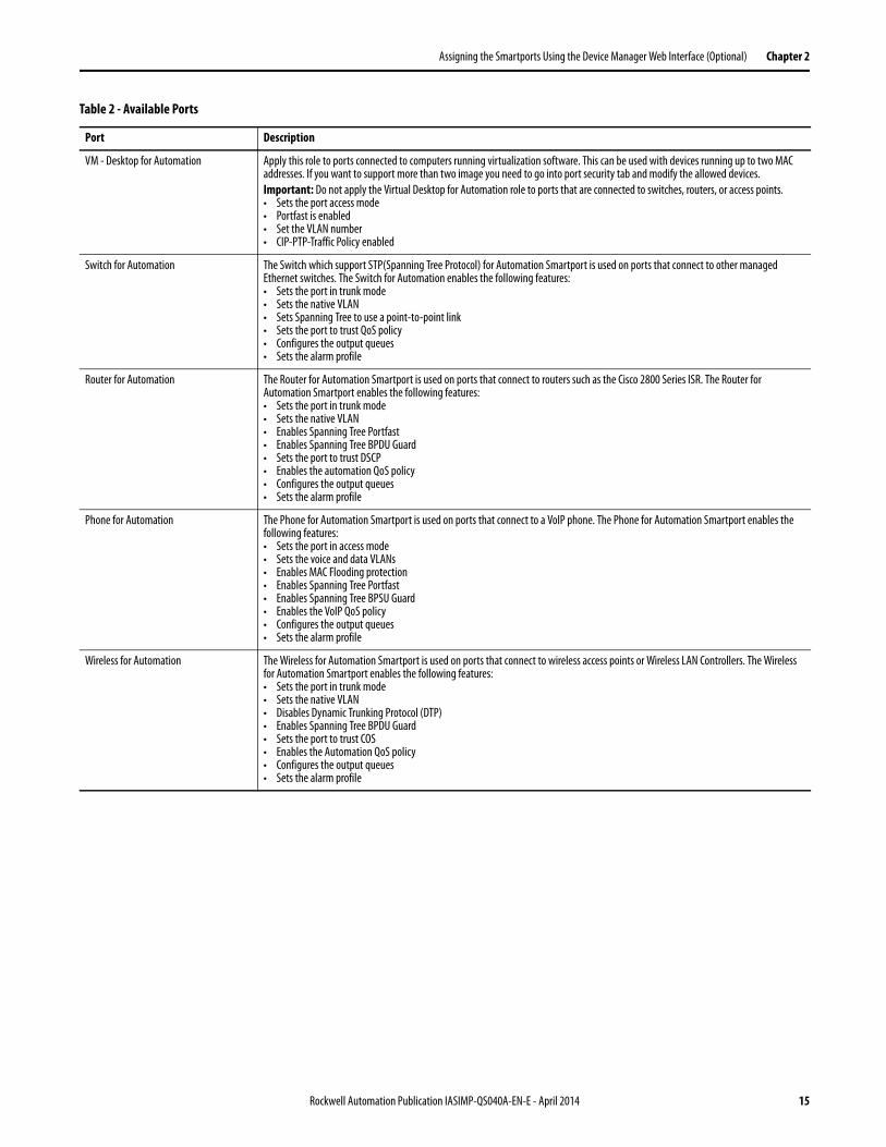
Table 2 - Available Ports
Port Description
Automation Device Macro The Automation Device Smartport should be used for any EtherNet/IP devices. This includescontrollers, HMI displays, distributed I/O, etc. The Automation Device Smartport enables thefollowing features:• Sets the port to host mode• Enables MAC flooding attack protection• Sets the VLAN number• Enables the automation QoS policy• Configures the output queues• Enables the alarm profile• Disables Cisco Discovery Protocol (CDP)
Multiport Automation device Apply this role to ports connected to multiport EtherNet/IP devices, such as multiport EtherNet/IP devices arranged in a linear or daisy chain topology, the 1783-ETAP module (for connection to the device port only), unmanaged switches (such as the Stratix 2000™) and managed switches with Remote Spanning Tree Protocol (RSTP) disabled:• Port is set to Access mode• No port security• Optimize queue management for CIP traffic
Desktop for Automation The Desktop for Automation Smartport should be used for PCs used on the Cell/Area zone EtherNet/IP network. It should not be used for any systems running virtual machines without turning the port security configuration off. The Desktop for Automation Smartport enables the following features:• Sets the port in access mode• Set the VLAN number• Enables MAC flooding attack protection• Enables Spanning Tree Portfast• Enables Spanning Tree BPDU Guard• Enables the automation QoS policy• Sets the alarm profile
14 Rockwell Automation Publication IASIMP-QS040A-EN-E - April 2014
Assigning the Smartports Using the Device Manager Web Interface (Optional) Chapter 2
VM - Desktop for Automation Apply this role to ports connected to computers running virtualization software. This can be used with devices running up to two MAC addresses. If you want to support more than two image you need to go into port security tab and modify the allowed devices.Important: Do not apply the Virtual Desktop for Automation role to ports that are connected to switches, routers, or access points.• Sets the port access mode• Portfast is enabled• Set the VLAN number• CIP-PTP-Traffic Policy enabled
Switch for Automation The Switch which support STP(Spanning Tree Protocol) for Automation Smartport is used on ports that connect to other managed Ethernet switches. The Switch for Automation enables the following features:• Sets the port in trunk mode• Sets the native VLAN• Sets Spanning Tree to use a point-to-point link• Sets the port to trust QoS policy• Configures the output queues• Sets the alarm profile
Router for Automation The Router for Automation Smartport is used on ports that connect to routers such as the Cisco 2800 Series ISR. The Router for Automation Smartport enables the following features:• Sets the port in trunk mode• Sets the native VLAN• Enables Spanning Tree Portfast• Enables Spanning Tree BPDU Guard• Sets the port to trust DSCP• Enables the automation QoS policy• Configures the output queues• Sets the alarm profile
Phone for Automation The Phone for Automation Smartport is used on ports that connect to a VoIP phone. The Phone for Automation Smartport enables the following features:• Sets the port in access mode• Sets the voice and data VLANs• Enables MAC Flooding protection• Enables Spanning Tree Portfast• Enables Spanning Tree BPSU Guard• Enables the VoIP QoS policy• Configures the output queues• Sets the alarm profile
Wireless for Automation The Wireless for Automation Smartport is used on ports that connect to wireless access points or Wireless LAN Controllers. The Wireless for Automation Smartport enables the following features:• Sets the port in trunk mode• Sets the native VLAN• Disables Dynamic Trunking Protocol (DTP)• Enables Spanning Tree BPDU Guard• Sets the port to trust COS• Enables the Automation QoS policy• Configures the output queues• Sets the alarm profile
Table 2 - Available Ports
Port Description
Rockwell Automation Publication IASIMP-QS040A-EN-E - April 2014 15

Chapter 2 Assigning the Smartports Using the Device Manager Web Interface (Optional)
Notes:
16 Rockwell Automation Publication IASIMP-QS040A-EN-E - April 2014

Publication IASIMP-QS040A-EN-E - April 2014Copyright © 2014 Rockwell Automation, Inc. All rights reserved. Printed in the U.S.A.
Rockwell Automation Support
Rockwell Automation provides technical information on the Web to assist you in using its products. At http://www.rockwellautomation.com/support you can find technical and application notes, sample code, and links to software service packs. You can also visit our Support Center at https://rockwellautomation.custhelp.com/ for software updates, support chats and forums, technical information, FAQs, and to sign up for product notification updates.
In addition, we offer multiple support programs for installation, configuration, and troubleshooting. For more information, contact your local distributor or Rockwell Automation representative, or visit http://www.rockwellautomation.com/services/online-phone.
Installation Assistance
If you experience a problem within the first 24 hours of installation, review the information that is contained in this manual. You can contact Customer Support for initial help in getting your product up and running.
New Product Satisfaction Return
Rockwell Automation tests all of its products to help ensure that they are fully operational when shipped from the manufacturing facility. However, if your product is not functioning and needs to be returned, follow these procedures.
Documentation Feedback
Your comments will help us serve your documentation needs better. If you have any suggestions on how to improve this document, complete this form, publication RA-DU002, available at http://www.rockwellautomation.com/literature/.
United States or Canada 1.440.646.3434
Outside United States or Canada Use the Worldwide Locator at http://www.rockwellautomation.com/rockwellautomation/support/overview.page, or contact your local Rockwell Automation representative.
United States Contact your distributor. You must provide a Customer Support case number (call the phone number above to obtain one) to your distributor to complete the return process.
Outside United States Please contact your local Rockwell Automation representative for the return procedure.
Rockwell Otomasyon Ticaret A.Ş., Kar Plaza İş Merkezi E Blok Kat:6 34752 İçerenköy, İstanbul, Tel: +90 (216) 5698400


![VLANs and Trunks - d12vzecr6ihe4p.cloudfront.net€¦ · Cisco IOS VLAN Commands To create a new VLAN on a Cisco IOS Ethernet switch, use the vlan [vlan-id] global configuration mode](https://img.pdfslide.us/doc/110x75/5e9ec5546ba88c31ec56c408/vlans-and-trunks-cisco-ios-vlan-commands-to-create-a-new-vlan-on-a-cisco-ios-ethernet.jpg)


![MonitorCommands - Cisco - Global Home Page · monitor session session_number destination {interfaces gigabitEthernet interface-id [network] |remote vlan vlan-id reflector-port gigabitEthernet](https://img.pdfslide.us/doc/110x75/5ffe52a35ccd7b2ad26460de/monitorcommands-cisco-global-home-page-monitor-session-sessionnumber-destination.jpg)