Embed Size (px)
Citation preview

International Journal of Scientific & Engineering Research, Volume 4, Issue 9, September‐2013 ISSN 2229‐5518 627
IJSER © 2013 http://www.ijser.org
Stratigraphy and Petroleum Plays of the late to middle Oligocene Sediments in the “XY” Field,
Onshore Niger Delta Basin, Nigeria Samuel Okechukwu Onyekuru
Abstract— Nigeria’s search for increased oil and gas reserves requires the discovery of additional petroleum plays using more accurate exploration techniques like sequence stratigraphy. Sequence stratigraphic technique was applied to sediments in the “XY” Field, onshore Niger Delta by integrating six well logs and biostratigraphic data to subdivide the field’s stratigraphic column into sequences, systems tracts and profitable plays. The analysis delineated seven complete (SEQs 1 to 7) and two incomplete 3rd order sequences. The key surfaces used for correlation across the sequences in Wells 002, 003, 005 and 001 were the 11.5Ma, 12.8Ma and 15.0Ma MFSs, while the link between these four wells and Wells 007 and 006 was the 15.9Ma MFS. The other constrained surfaces between Wells 007 and 006 were the 17.4Ma, 19.4Ma and 20.7Ma MFSs. These surfaces were delineated at varying depths in the wells, suggesting the existence of faults in the well field. The most laterally continuous sandstone unit, however, is the faulted prograding wedge complex (PGC) sands of SEQ 4 which represented the main petroleum plays in the field. Cyclic alternation of Transgressive Systems Tracts (TST), High-stand Systems Tracts (HST) and Lowstand Systems Tracts (LST) in the well field is suggestive of a union of the elements of a petroleum system which constitute favourable conditions for the generation, migration and structural and stratigraphic entrapment of hydrocarbons.
Index Terms— Petroleum, Plays, Sequence, Straigraphy, Faults, Compartmentalization, Hydrocarbon, Reserves.
—————————— ——————————
1 INTRODUCTION
xploration and exploitation activities in Nigeria had been concentrated in the Tertiary Niger Delta sequences of Eo-
cene to Pliocene age, until recently when exploration efforts are gradually being shifted to the offshore (Pliocene–Pleistocene) sections. These areas have accounted for the coun-try’s current oil reserves estimated at about 35 billion barrels and an average annual reserve addition of about 800 million barrels in the last ten years [1]. These reserves that were main-ly derived from the onshore, offshore and recently the deep offshore parts of the Niger Delta are presently intensely de-veloped. The Nigerian oil and gas industry is presently faced with the challenge of achieving the national crude oil reserves target of 40 billion barrels and production of increased volumes of Liq-uefied Natural Gas (LNG) in order to meet export and domes-tic needs. The domestic need is bolstered by the current gov-ernment policy thrust for additional gas turbines for power generation and industrial projects [2]. Therefore, the future reserve/production ratio for oil/gas in Nigeria will be a cause for serious concern based on the present available reserves data, if additional reserves are not discovered. The search for additional oil and gas reservoirs in the region will, therefore, require more accurate techniques of strati-
graphic analysis [3]. These techniques will assist in the discovery of hithertho hidden, deep and tight reservoirs which will give the required boost to the existing reserves. Sequence stratigraphy has become an indispensable tool in hydrocarbon exploration because of its ability to provide a chronostratigraphic framework for the analy-sis and correlation of lithic fills in basins that are deposited in re-sponse to sea level changes, tectonism and sediment supply. The search for additional reserves in the Niger Delta Baasin can be en-hanced by the use of this integrated approach for stratigraphic analy-sis and prediction [4], [5], [6], [7]. It will also give a better under-standing of the linkage between sedimentation patterns in different parts of the basin and location of reservoirs, their continuity and seal prone zones (traps) and perfectly predicts bypassed pay zones and step-out potentials in a basin [8]. Therefore, to realize optimal hydrocarbon exploration, recovery and production, the understanding of the depositional setting and location of play elements within the depositional setting is required for a real-istic or near realistic representation of the subsurface and paleoenvi-ronmental conditions within the basin. The aim of the present study in the onshore, Niger Delta is to subdi-vide the stratigraphic column of the “XY” well field into sequences and systems tracts based on the integration of well logs and high resolution biostratigraphic data for the delineation of reservoirs, their continuity and other elements of the petroleum system (source, traps, e.t.c) for the sustainable development of the resource in the region. 2 LOCATION OF STUDY The “XY” Field (a designation used for propriety purposes) is locat-ed at the fringe of the Greater Ughelli Depobelt in the Niger Delta Basin (Fig. 1). The Niger Delta is situated in the Gulf of Guinea on the west coast of central Africa (Fig. 1). It lies on Latitudes 40001N and 60031N and Longitudes 40301E and 80301E. During the Tertiary, the delta built out into the Atlantic Ocean at the mouth of the Niger-
E
———————————————— Samuel Okechukwu Onyekuru is currently a senior lectutrer in sedimentary
and petroleum geology in the federal University of Technology,Owerri, Nigeria, PH-+234- 8037175256. E-mail: [email protected]
IJSER

InternISSN 2
BenuekilomEocening deeach slargeskm2 [over Depobcrease
3 PRThe ogeoloThe nhinge easterthe Abhinge boundto themost the twbathythan tSedimscale pro-defaciesof theprogreprograthe AtThe scollapbilizenin Flistricward with ged sed
national Journal o2229-5518
e system on anmeters of predone to the presenepobelts that restage of its devst regressive de10], a volume o10 km in thebelt, however, ed steepness sea
ROVINCE GEonshore portion gy of southern
northern bounda line south of rn boundary is bakaliki High a line borderingdary of the prove east, the easteWest African two-kilometer smetric contour
two kilometers tmentary deposit
lithostratigraphelta facies of ts of the Agbada e Benin Formaessively youngeadation of depotlantic Ocean patratigraphy of t
pse of clastic wd under the loa
Formation depoc normal faults
(Fig. 4). Blockgrowth strata, cdiment transpor
of Scientific & En
n area of catchmominantly savannt, the delta hasepresent the movelopment [9]. eltas in the worof 500,000 km3
e basin depoceoverlies a relatawards [9].
OLOGY of the Niger D
n Nigeria and sary is the Beninthe West Africdefined by outc
and further east-g the adjacent Pvince is definern boundary of
transform-fault sediment thicknr in areas wheto the south ands in the basin h
hic units (Fig. 3the Akata Form
Formation, andation [13], [14],er farther into tositional enviroassive margin. the study area i
wedges as shalesad of progradinsits. A series owere formed a
ks down-droppchanged local drt paths into the
ngineering Resea
ment more thannna-covered los prograded souost active portioThese depobel
rld with an area3 [11] and a sedenter [12]. Thetively shallow
Delta Province issouthwestern Cn flank- an east-can Basement Mcrops of Cretac-south-east by tPrecambrian rod by the Came
f the Dahomey passive marginness contour ore sediment thd southwest (Figave been divide3): the basal Pa
mation, Eocene d Oligocene-Re, [15]. These fthe basin, recordonments of the
is complicated bs of the Akata F
ng deltaic Agbaof large-scale, bas underlying sped across thesdepositional slope basin. For any
rch Volume 4, Is
htt
n a million squowlands. From uthwestward, foons of the deltalts form one of a of some 300,diment thicknese Greater Ughbasement with
s delineated by Cameroon (Fig. -northeast trendMassif. The noeous sedimentsthe Calabar flanocks. The offsheroon volcanic lbasin (the easte
n) to the west, or the 4000-mehickness is greg. 2). ed into three laraleocene to Recto Recent, par
ecent, fluvial facformations becoding the long-te
e Niger Delta o
by syndepositioFormation are m
ada and fluvial basinward-dipp
shales diapired e faults and filpes and compliy given depobel
sue 9, September
IJSER © 2013 tp://www.ijser.org
uare the rm-a at
f the 000 s of
helli in-
the 2).
ding rth-
s on nk-a hore line ern-and eter ater
rge-cent ralic cies ome erm onto
onal mo-Be-
ping up-lled cat-lt in
the Nigedepositiostructuregrowth fly spaceparts of near the
r‐2013
er Delta provinon of the Benines, including sfault crests, baced flank faults [f the Agbada F
top of the Akat
nce, gravity ten Formation, wshale diapirs, ck-to-back featu[13], [16]. Thes
Formation and fta Formation.
ectonics was cowhich are expres
roll-over anticures and steeplyse faults mostlyflatten into det
636
ompleted beforssed in complelines, collapse
y dipping, closey offset differentachment plane
e x d
e-nt es
IJSER

InternISSN 2
5 DaThe d‘XY” and reevents1) andacquirPort (DPRsectiothose
5.1 SeAthousectiowell lwell lNigerinformfrom t 5.2. DtionalThe wphysicgammclay-mresponThe lsand, mud wAPI (units
national Journal o2229-5518
ata Sets and Mdata sets used fo Field, Greater esistivity logs (s) including pald the Niger Delred from Shell Harcourt, thro
R), Nigeria. Theons of the studie
depths.
equence Stratigugh sequence sons, its principlelogs [3]. Sequelog suites from r Delta Basin wmation (stratigrathe wireline log
Determination l Settings wireline logs wcal criteria ext
ma ray log recorminerals) commnses and conselog is thus usewhich contains
with high gamm(American Petr(in anhydrite) to
of Scientific & En
Methodology or this study inUghelli depobe
(Fig. 5), biostralynological andta ChronostratigProducing and
ough the Direce non-availabiled intervals, ho
graphic Applicstratigraphy waes can readily b
ence stratigraphthe “XY” Fieldas achieved by aphic markers) g suites using th
of Lithology,
were used to detracted from thrds radioactivitmonly have relequently taken ed to infer deps little mud, wilma ray signal. Goleum Instituteo over 200 API
ngineering Resea
ncluded 6 well lelt, logged withatigraphic data d foraminiferal igraphic Chart [Development C
ctorate of Petrity of GR and
owever, affected
cation in “XY”s originally desbe applied to o
hic analysis of ed in the Greaterthe integration and lithologica
he approach of [
Stacking Patt
elineate lithofahe electric logty of formationslatively high gas good measu
positional energl have low gam
Gamma ray value) units and ran units in shales.
rch Volume 4, Is
htt
log suites from h gamma ray (G(faunal zones
information (Ta19]. The data wCompany (SPDroleum Resour
d SP logs at sod interpretation
” Field signed for seism
outcrops, cores each of the six r Ughelli depobof biostratigrap
al data distilled [5].
terns and Depo
acies based on gs’ responses. Ts, hence shales
gamma radioactures of grain sgy. Coarse-grai
mma ray value, tues are measurednge from very .
sue 9, September
IJSER © 2013 tp://www.ijser.org
the GR) and able
were DC), rces ome ns at
mic and (6)
belt, phic out
osi-
the The (or
tive size. ned
than d in few
Table 1.of Well 0
Form C
D1000
D1000
D1100
D1100
D2000
D2000
D3000
D3000
D3000_
D4000
D4000
D5000
D5000
E1000
E1000
E2000
E2000
E2000_
E2000_
E3000
E3000
E3100
E3100
E4000
E4000
E4000_
r‐2013
. Representativ001 Greater U
Code
base
top
base
top
base
top
base
top
_HWC_contact
base
top
base
top
base
top
base
top
_DHO_contact
_HWC_contact
base
top
base
top
base
top
_HWC_contact
ve StratigraphiUghelli Depobel
Depth
63
63
64
64
66
6
69
66
t 66
69
69
73
70
74
74
76
7
7
t 7
76
76
77
77
80
79
t 79
ic Markers lt
(AH), Ft
390
350
487
403
656
542
960
677
689
998
972
340
004
465
402
610
518
532
574
690
647
792
782
026
933
952
636
IJSER

International Journal of Scientific & Engineering Research Volume 4, Issue 9, September‐2013 ISSN 2229-5518 636
IJSER © 2013 http://www.ijser.org
Form Code Depth (AH), Ft
E5000 base 8095
E5000 top 8075
E6000 base 8253
E6000 top 8179
E8000 base 8515
E8000 top 8407
E9000 base 8617
E9000 top 8593
F1000 base 8760
F1000 top 8703
F1400 base 8917
F1400 top 8768
F2000 base 9178
F2000 top 9123
F2000_DLG_contact 9155
F2100 base 9229
F2100 top 9202
F2100_DHO_contact 9203
F2200 base 9260
F2200 top 9250
F2300 base 9350
F2300 top 9328
F3000 base 9688
F3000 top 9360
F3000_DHO_contact 9362
F3000_HWC_contact 9404
F3100 base 9782
F3100 top 9720
F4000 top 10172
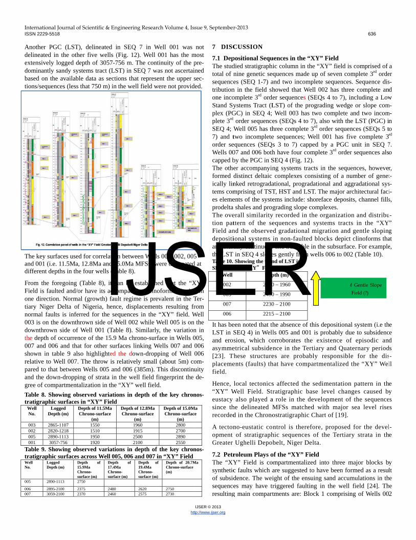
ZZC 7464 The intervals of progradation, retrogradation and aggradation were delineated from the succession patterns of strata expressed in the logs, which depict various parasequences and/or parasequence sets. These patterns which display vertical occurrences of repeated cycles of coarsening upwards (CU) or fining upwards (FU) sequences were inferred from the gamma ray log signatures. The environment of deposition for the respective units was inferred from the gamma log expression of grain size [5] and depositional systems determination distilled from stacking patterns [3].
Progradation or Cleaning-up Trend (funnel shape) means a coarsening upward sequence (Fig. 6). It also means a gradual upward decrease in gamma ray response. In shallow marine settings, this trend reflects a change from shale-rich into sand-rich lithology and
an upward increase in depositional energy with shallowing-upward and coarsening. In deep marine settings, this trend reflects an in-crease in the sand content of turbidite bodies [20]. Retrogradation or Dirtying-up Trend (bell shape) means a fining upward sequence or a gradual upward increase in gamma response (Fig. 6). This trend may reflect upward fining (example, a lithologic change from sand to shale) or upward fining of sand beds in a thinly interbedded sand-shale unit. This trend usually implies a decrease in depositional energy. In non-marine settings, fining upward is pre-dominant within meandering or tidal channel deposits with an up-ward decrease in fluid velocity within a channel (coarser sediments are usually at the base of channels). In shallow-marine settings, this trend usually reflects an upward deepening and a decrease in deposi-tional energy (net landward shoreline movement). In deep-marine settings, this trend reflects waning of submarine fans resulting in the reduction of sand contents [20]. Aggradation or Boxcar Trend (cylindrical or blocky shape) means piling up of sediments on top of each other, hence the gamma ray shows neither increase nor decrease (Fig 6.). Sometimes the gamma ray response has low gamma and sharp boundaries and no internal change. This trend is predominant in fluvial channel sands, turbidites (typically with greater range of thickness) and aeolian sands. Evaporites also can have a cylindrical gamma trend.
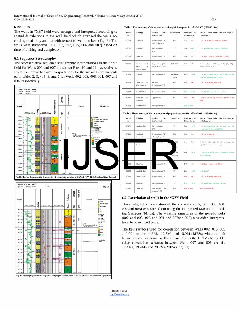
5.3 Definition of Key Stratigraphic Sequences from Logs The definition of key stratigraphic surfaces from well logs, which includes for example, Sequence Boundary (SB) and Maximum Flooding Surface (MFS) and their relative ages was done by identi-fying candidates and events of the surfaces in the following ways: Candidate SBs on log-motifs were marked by the sharp-based bot-tom of the basin floor thicks and incised-valley fills and in updip areas by the sharp-top of the uppermost prograding transgressive parasequence, low gamma, high resistivity and the use of the provid-ed stratigraphic markers [21]. Candidate SB was also identified from facies discontinuities in the logs. From the logs, a change from for-ward stepping to back stepping parasequence stacking pattern was looked out for in the gamma ray log. The trend of shale resistivity shows increased resistivity towards SB and a decrease away from SB. From the biofacies data, candidate SB was inferred using the provided stratigraphic markers. Facies expression of the SB depends on the paleogeographic location of the section in the basin and the Systems Tract.
MFS and condensed sections were identified from log trend bounda-ries and/or log character and the provided biostratigraphic data. Gamma ray logs have high values at MFS and condensed sections. Shale resistivity values decrease towards MFS and increase away from MFS [21]. Faunal/floral density trends display increased densi-ty towards flooding surface and decreased density away from the flooding surface. 5.4 Delineation of Systems Tracts Delineation of systems tracts was done after the surfaces were identi-fied. Parasequence stacking patterns were used to identify the Lowstand Systems Tracts (LST), Transgressive Systems Tracts (TST) and Highstand Systems Tracts (HST), enveloped by the con-strained surfaces (MFS, TS and SB). The enveloping Sequence Boundary (SB) of a sequence, or its down dip correlative conformity, lies between the Highstand Systems Tract (HST) and the Lowstand Systems Tract (LST) according to the se-
IJSER
InternISSN 2
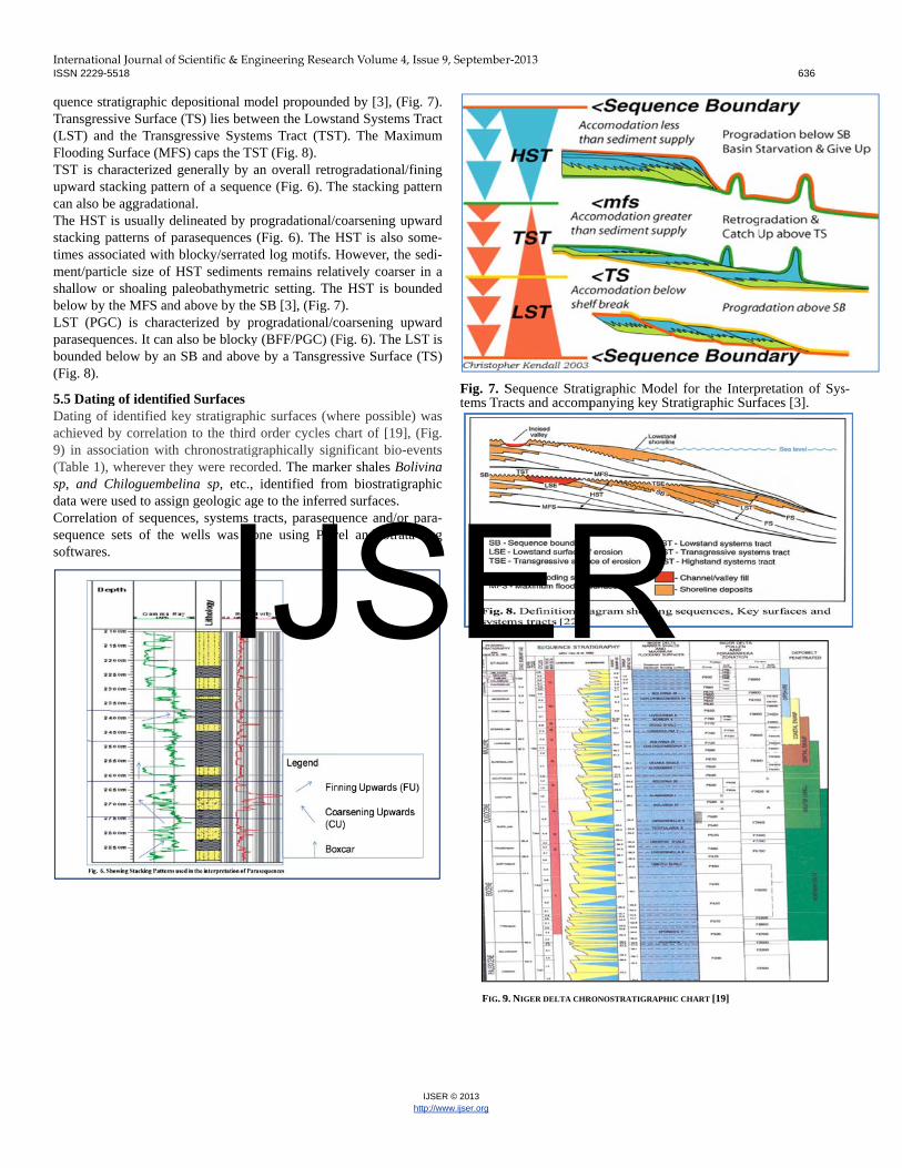
quencTrans(LST)FloodTST iupwarcan alThe Hstackitimes ment/shallobelowLST parasebound(Fig.
5.5 DDatinachiev9) in (Tablesp, andata wCorresequesoftw
national Journal o2229-5518
ce stratigraphic gressive Surfac) and the Tran
ding Surface (Mis characterizedrd stacking pattlso be aggradatiHST is usually ing patterns of associated with
/particle size ofow or shoaling w by the MFS an
(PGC) is charequences. It canded below by a8).
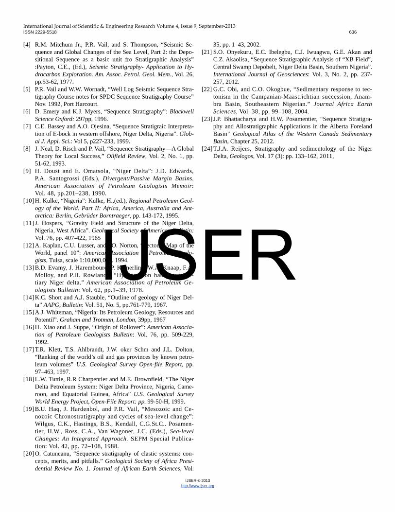
ating of identifg of identified ved by correlatassociation wit
e 1), wherever nd Chiloguembwere used to asselation of sequeence sets of theares.
of Scientific & En
depositional mce (TS) lies betwsgressive Syste
MFS) caps the TSd generally by tern of a sequenional. delineated by pparasequences h blocky/serratef HST sedimenpaleobathymet
nd above by theracterized by pn also be blockyan SB and abov
fied Surfaces key stratigraph
tion to the thirdth chronostratigthey were reco
belina sp, etc.,sign geologic agences, systems e wells was do
ngineering Resea
model propoundeween the Lowstems Tract (TSTST (Fig. 8). an overall retronce (Fig. 6). Th
progradational/c(Fig. 6). The H
ed log motifs. Hnts remains relatric setting. Thee SB [3], (Fig. 7progradational/cy (BFF/PGC) (F
ve by a Tansgre
hic surfaces (whd order cycles cgraphically signrded. The mark identified fromge to the inferretracts, parasequone using Petr
rch Volume 4, Is
htt
ed by [3], (Fig.tand Systems TrT). The Maxim
ogradational/finhe stacking patt
coarsening upwHST is also somHowever, the se
atively coarser ie HST is boun7). coarsening upwFig. 6). The LSTssive Surface (T
here possible) wchart of [19], (Fnificant bio-eveker shales Bolivm biostratigraped surfaces. uence and/or parel and Strata b
sue 9, September
IJSER © 2013 tp://www.ijser.org
. 7). ract
mum
ning tern
ward me-edi-in a
nded
ward T is TS)
was Fig. ents vina phic
ara-bug
Fig. 7. Stems Tra
FIG. 9
r‐2013
Sequence Stratiacts and accomp
9. NIGER DELTA CHR
igraphic Modelpanying key Str
RONOSTRATIGRAPHIC
l for the Interpratigraphic Surf
C CHART [19]
636
pretation of Sysfaces [3].
s-
IJSER
InternISSN 2
6 RES
The wspatiacordinwells time o 6.1 SeThe refield fwhile ed in 006, r
national Journal o2229-5518
ULTS wells in “XY” fal distributions ng to affinity anwere numbere
of drilling and c
equence Stratigepresentative sefor Wells 006 a the comprehentables 2, 3, 4, 5
respectively.
of Scientific & En
field were arranin the well fie
nd not with resped (001, 002, 0completion.
graphy equence stratigrand 007 are shonsive interpretat5, 6, and 7 for W
ngineering Resea
nged and interpeld which arranpect to well num003, 005, 006 a
raphic interpretown Figs. 10 antions for the sixWells 002, 003,
rch Volume 4, Is
htt
preted accordingnged the wells mbers (Fig. 5). Tand 007) based
ations in the “Xnd 11, respectivx wells are prese
005, 001, 007
sue 9, September
IJSER © 2013 tp://www.ijser.org
g to ac-
The d on
XY” vely, ent-and
Table 2. T
Interval
(m)
2820-2755
2755-2700
2700-2460
2460-1960
1960-1915
1915-1640
1640-1510
1510-1460
1460-1218
Table 3. Th
Interval
(m)
2865-2800
2800-2400
2400-1990
1990-1960
1960-1900
1900-1550
1550-1260
1260-1160
1160-1107
6.2 Corr
The stra007 and ing Surf(002 andtions bet
The keyand 001 betweenother co17.4Ma,
r‐2013
The summary of the seq
Lithology Stacki
tern/L
Sand/shale Progra
– Block
Sand/Shale Retrog
(FU)
Shale/Sand Progra
Stacks of Sand/
Shale + Silt
iontercalations
Progra
Blocky
Sand/Shale Retrog
Shale/Sand i.e.
(Bar Deposits)
Genera
Progra
Sand/Silt/Shale Retrog
Sand (+ Shale
Laminae)
Aggrad
Sand/Silt/Shale Retrog
he summary of the sequ
Lithology Stacki
tern/L
SandSilt//Shale Retrog
(FU)
Sand/shale
intercalations
Progra
– Block
Sand/Shale
laminae
Blocky
Sand/Shale Retrog
Shale/Sand Progra
Sand/Silt/Shale Retrog
Shale + Sand) Progra
Sand/Shale Retrog
Shale/Silt Aggrad
section
relation of wel
atigraphic corre006) was carri
faces (MFSs). d 003; 005 andtween well pair
y surfaces used are the 11.5M
n these wells anorrelation surfa, 19.4Ma and 20
quence stratigraphic in
ing Pat-
Log Motif
Systems Trac
adational (CU)
ky log motif
HST
gradational TST
adational (CU) HST
adation (CU):
y SP log Motif
LST (PGC)
gradation (FU) TST (Short-
lived)
ally
adational (CU)
HST
gradation (FU) TST
dational HST
gradation (FU) TST
uence stratigraphic int
ing Pat-
Log Motif
Systems Trac
gradational TST
adational (CU)
ky log motif
HST
y- Serrated LST (PGC)
gradation (FU) TST (Short
interval)
adational (CU) HST
gradation (FU) TST
adational (CU) HST
gradation (FU) TST
dational (Toe
n of HST)
HST
ls in the “XY”
elation of the sied out using thThe wireline s
d 001 and 007ars.
for correlationMa, 12.8Ma andnd wells 007 anfaces between 0.7Ma MFSs (F
nterpretation of Well 00
ct Depth/type of
Chrono- Surface
Da
19
2755 -SB 15
2700 - MFS 15
2460 -SB 13
1960 -TS Su
ren
1915 -MFS 12
Uv
1640 -SB 12
1510 -MFS 11
1460 -SB 10
de
Peak not seen -
erpretation of Well 003
ct Depth/type of
Chrono- Surface
Da
19
2800 - MFS 15
oc
2400 -SB 13
1990 - TS SP
hig
1960 -MFS 12
th
1900 -SB 12
1550 -MFS 11
1260 -SB 10
1160 -MFS 11
Peak not seen (L
Field
six wells (002, he interpreted Msignatures of thand 006) also a
n between Welld 15.0Ma MFSsd 006 is the 15Wells 007 an
Fig. 12).
636
02 (2820-1218 m)
ate of Chrono- Surface (Ma; a
988)/Remarks
5.5 (Low SP and high Resistivity Va
5.0 (High SP & low Resistivity logs
3.1 (High resistivity & low Sp @
udden deflection of SP log to the
newed transgression
2.8 (High SP, low resistivity and to
Uvigerina sp at the depth of 1866m)
2.1 (Low SP & high resistivity)
1.5 (High SP and Low Resistivity va
0.6 (Low SP and high resistivity lo
epth
3 (2865-1107 m)
ate of Chrono- Surface (Ma; a
988)/Remarks
5.0 (retrogradational SP log m
ccurrence of Bolivina sp @ 2700m}
3.1 (Low SP Values)
P log showed a sudden deflection
gh SP) initiating another transgressi
2.8 (High SP and top ooccurrence o
e depth 1920m)
2.1 (High resistivity @ 1900m)
1.5 (High SP)
0.6 (Low SP & high resistivity)
1.5 (High SP and Low Resistivity va
Late rise of sea level)
003, 005, 001Maximum Floodhe genetic wellaided interpreta
ls 002, 003, 00s; while the lin.9Ma MFS. Th
nd 006 are th
fter Haq et al.,
lues)
values)
2460 m)
left (High SP) =
p ooccurrence of
lue)
og values at that
fter Haq et al.,
motif and rich
to the right (i.e.
on
f Uvigerinassp at
lue)
1, d-ls a-
5 k e e
IJSER

International Journal of Scientific & Engineering Research Volume 4, Issue 9, September‐2013 ISSN 2229-5518 636
IJSER © 2013 http://www.ijser.org
Table 4. The Summary of the sequence stratigraphic interpretation of Well 005 (2890-1113 m)
Interval
(m)
Lithology Stacking
Pattern/Log
Motif
Systems
Tract
Depth/type of
Chrono- Surface
Date of Chrono- Surface (Ma; after Haq et al.,
1988)/Remarks
2890-
2885
Silt/Shale Retrogradational
(FU)
TST 2890 - MFS 15.0 (very Low resistivity)
2885-
2770
Shale/Silt/Sand Progradational
(CU)
HST 2770 -SB 13.1 (Low GR & High resistivity)
2770-
2500
Shale/Silt/Sand Retrogradational
(FU)
TST 2500 - MFS 12.8 (very Low resistivity & high GR)
2500-
2300
Shale/Silt/Sand Progradational
(CU)
HST 2300 -SB 12.1 (High Resistivity)
2300-
1950
Sand/Shale Retrogradation
(FU)
TST 1950 -MFS 11.5 (Top occurrence of Nonion sp at 1824m)
1950-
1610
Shale/Sand Progradational
(Blocky Motif)
HST 1610 -SB 10.6 (High resistivity)
1610-
1400
Sand/Shale Retrogradation
(FU)
TST 1400 -MFS 10.4
1400-
1200
Shale/Silt/Sand Progradational
(Blocky Motif)
HST 1200 -SB 10.35 (High resistivity and low SP values esp.
b/w 1285-1200)
1200-
1113
Sand/Shale Retrogradation
(FU)
TST Peak not seen Abrupt shift of Resistivity log to the left and SP log
to the left is suggestive of transgression
Table 5.The summary of the sequence stratigraphic interpretation of Well 001 (3057-756 m)
Interval
(m)
Lithology Stacking
Pattern/Log
Motif
Systems
Tract
Depth/type of
Chrono- Surface
Date of Chrono- Surface (Ma; after Haq et al.,
1988)/Remarks
3057-
2865
Sand/Shale Progradational
(CU)
HST 2865 -SB 16.7 (Low GR & High resistivity)
2865-
2750
Sand/Silt/Shale Retrogradational
(FU)
TST 2750 - MFS 15.9 (very Low resistivity & high GR)
2750-
2665
Shale/Sand Progradational
(CU)
HST 2665 -SB 15.5 (Low GR & High Resistivity)
2665-
2550
Sand/Silt/Shale Retrogradation
(FU)
TST 2550 -MFS 15.0 (Low Resistivty; NO SP and GR logs at this
depth; Rich occurrence of Bolivina sp at depth 2598
assisted interpretation)
2550-
2300
Shale/Sand Progradational
(CU)
HST 2300 -SB 13.1 (High resistivity)
2300-
2100
Silt/Shale Retrogradation
(FU)
TST 2100 -MFS 12.8 (Low Resistivity & high GR)
2100-
2040
Shale/thin sand
unit
Progradational
(CU)
HST 2040 -SB 12.1 (High resistivity)
2040-
1920
Sand/Shale Retrogradation
(FU)
TST 1920 -MFS 11.5 (Low Resistivity value; Top occurrence of
Nonion sp at 1854m)
1920-
1690
Sand Blocky
(Channels)
HST 1690 -SB 10.6 (High resistivity)
1690-
1370
Sand/Silt/Shale Retrogradation
(FU)
TST 2370 -MFS 10.4 (Low Resistivty)
1370-
1030
Shale/Sand Progradational
(CU)
HST 1030 -SB 10.35 (1035m is the base of sand body = incised
valley fill)
1035-756 Silt/Sand Blocky
(Channels)
LST
(PGC)
End of phase (TS) not seen at the top of the interval
Table 6. The summary of the sequence stratigraphic interpretation of Well 007 (3059-2100 m)
Interval (m) Lithology Stacking
Pattern/Log Motif
Systems
Tract
Depth/type of
Chrono- Surface
Date of Chrono- Surface (Ma; after Haq et al.,
1988)/Remarks
3059-2950 Shale Retrogradational
(FU)
TST 2950 - MFS 22.0 (High GR, high SP & low Resistivity logs values)
2950-2830 Shale/Sand Progradational (CU) HST 2830 -SB 21.8 (Low GR and High resistivity)
2830-2730 Stacks of Sand/
Shale
Retrogradational
(FU)
TST 2730 -MFS 20.7 (High GR and SP with low Resistivity log values at
2730)
2730-2630 Shale/Sand i.e.
(Distr. Mouth
Bar Deposits)
Generally
Progradational (CU)
HST 2630 -SB 20.4 (Low GR, low SP & high resistivity)
2630-2575 Sand/Shale Retrogradation (FU) TST 2575 -MFS 19.4 (High SP and Low Resistivity values)
2575-2535 Shale + Sand Aggradational/
Progradational
HST 2535 -SB 17.7 (Low GR and high resistivity log values at that depth
2535-2460 Predominantly
Shale
Retrogradation (FU) TST 2460 -MFS 17.4 (High SP and Low Resistivity values)
2460-2410 Shale/Sand Progradational (CU) HST 2410 -SB 16.7 (Low GR and high resistivity log values at that depth
2410-2370 Predominantly
Shale
Retrogradation (FU) TST 2370 -MFS 15.9 (High SP and Low Resistivity values; Top occurrence
of Chiloguembelina-3 at 2311)
2370-2230 Shale/Silt/Sand Progradational (CU) HST 2230 -SB 15.5 (Low GR and high resistivity log values at that depth
2230-2100 Predominantly
Sand (Channel
Fill Deposits)
Progradational (CU) LST
(PGC)
Peak of the interval was not Observed
-
Table 7. The summary of the sequence stratigraphic interpretation of Well 006 (2895-2100 m)
Interval (m) Lithology Stacking Pat-
tern/Log Motif
Systems
Tract
Depth/type of
Chrono- Surface
Date of Chrono- Surface (Ma; after Haq et al.,
1988)/Remarks
2895-2870 Sand Progradational (CU) HST 2870 -SB 21.8 (Low GR and High Resistivity). Onset of this
regressive phase was not observed at the TD.
2870-2750 Predominantly
Shale units
Retrogradational
(FU)
TST 2750 -MFS 20.7 (High GR and low Resistivity log values at 2750)
2750-2670 Shale/Sand Progradational (CU) HST 2670 -SB 20.4 (Low GR & high resistivity)
2670-2620 Sand/Silt/Shale Retrogradation (FU) TST 2620 -MFS 19.4 (High SP and Low Resistivity values)
2620-2570 Shale + Sand Progradational
/Blocky log motifs
HST 2570 -SB 17.7 (Low GR and high resistivity log values at that depth
2570-2480 Sand/Shale Retrogradation (FU) TST 2480 -MFS 17.4 (High GR and Low Resistivity values)
2480-2420 Shale/Sand Progradational (CU) HST 2420 -SB 16.7 (Low GR and high resistivity log values at that depth
2420-2375 Sand/ Shale Retrogradation (FU) TST 2375 -MFS 15.9 (High SP and Low Resistivity values; Top occurrence
of Chiloguembelina-3 at 2332 m)
2375-2215 Shale/Sand Progradational
(CU)/Bloky log
motifs
HST 2215 -SB 15.5 (Low GR and high resistivity log values at that depth)
2215-2100 Stacks of
blocky log
motifs (Sands
of Channel
Deposits)
Progradational (CU)/
Blocky
LST
(PGC)
Peak of this interval was not Observed at the top depth of the analysed interval of the
well
-
The result of the interpretations across the well field showed that Well 002 has three complete and one incomplete 3rd order sequence (SEQs 4 to 7), including a Low Stand Systems Tract (LST) of the prograding wedge or slope complex (PGC) in SEQ 4; Well 003 has two complete and two incomplete 3rd order sequences (SEQs 4 to 7), also with the LST (PGC) in SEQ 4; Well 005 has three complete 3rd order sequences (SEQs 5 to 7) and two incomplete sequences; Well 001 has five complete 3rd order sequences (SEQs 3 to 7) capped by a PGC unit in SEQ 7. Wells 007 and 006 both have four complete 3rd order sequences also capped by the PGC in SEQ 4 (Fig. 12). The LST in SEQ 4 delineated in four wells (002, 003, 007 and 006) was not observed in Wells 005 and 001. The unit may have been eroded before the deposition of the overlyng TST.
IJSER
InternISSN 2
Anothdelineextensdominbasedtions/
The kand 0differ
From Field one dtiary norma003 isdownthe de007 ashownrelativpared and thgree o
Tabletratig
Well No.
003 002 005 001
TabletratigWell No.
005 006 007
national Journal o2229-5518
her PGC (LSTeated in the othsively logged dnantly sandy sy
d on the availab/sequences (less
key surfaces use01 (i.e. 11.5Maent depths in th
the foregoing is faulted and/o
direction. NormNiger Delta ofal faults is infes on the downththrown side ofepth of occurrenand 006 and than in table 9 alve to Well 007.
d to that betweehe down-droppof compartment
8. Showing obgraphic surfaces
Logged Depth (m)
2865-1107 2820-1218 2890-1113 3057-756
9. Showing obgraphic surfaces
Logged Depth (m)
D1Cs
2890-1113 2
2895-2100 23059-2100 2
of Scientific & En
T), delineated iher five wells (depth of 3057-7ystems tract (LSble data as sectis that 750 m) in
ed for correlatioa, 12.8Ma and 1he four wells (Ta
(Table 8), it cor have its accoal (growth) fauf Nigeria, hencerred for the sehrown side of Wf Well 001 (Tabnce of the 15.9 at for other surso highlighted . The throw is n Wells 005 aning of strata in talization in the
bserved variatios in “XY” FieldDepth of 11.5Ma Chrono-surface
(m) 1550 1510 1950 1920
bserved variatios across Well 00Depth of 15.9Ma Chrono-surface (m)
Depth17.4MChrosurfa
2750 2375 2480 2370 2460
ngineering Resea
in SEQ 7 in W(Fig. 12). Well 756 m. The conST) in SEQ 7 wions that represthe well field w
on between Well5.0Ma MFSs) wable 8).
can be establishompanying clinult regime is prece, displacemenequences in theWell 002 while ble 8). SimilarlMa chrono-sur
rfaces linking Wthe down-drop
relatively smallnd 006 (385m).
the well field “XY” well fiel
ons in depth ofd
Depth of 12.8Ma Chrono-surface
(m) 1960 1915 2500 2100
ons in depth of05, 006 and 007 h of
Ma no-
ace (m)
Depth o19.4Ma Chrono-surface (m
2620 2575
rch Volume 4, Is
htt
Well 001 was 001 has the m
ntinuity of the pwas not ascertaisent the upper swere not provid
ls 003, 002, 005were delineated
hed that the “Xnoforms dippingevalent in the Tnts resulting fr
e “XY” field. WWell 005 is on
ly, the variationrface in Wells 0Wells 007 and 0pping of Well 0l (about 5m) coThis discontinufingerprint the ld.
f the key chron
Depth of 15.0MChrono-surfac
(m)2800270028902550
f the key chronin “XY” Field
of
m)
Depth of 20.7MChrono-surface (m)
27502730
sue 9, September
IJSER © 2013 tp://www.ijser.org
not most pre-ned sec-
ded.
5 d at
XY” g in Ter-rom
Well the
n in 005, 006 006 om-uity de-
nos-
Ma e
nos-
Ma
7 DISC
7.1 DepThe studtotal of nsequencetributionone incoStand Syplex (PGplete 3rd
SEQ 4; W7) and torder seWells 00capped bThe otheformed dically lintems comes elemeprodelta The ovetion patField andepositiare laterathe LST Table 10. SEQ 4 in
Well
002
003
007
006
It has beLST in Sand erosasymme[23]. Tplacemefield.
Hence, “XY” Weustacy since threcorded
A tectonopment Greater
7.2 PetrThe “XYsyntheticof subsidsequenceresulting
r‐2013
CUSSION
positional Sequdied stratigraphnine genetic sees (SEQ 1-7) a
n in the field shomplete 3rd ordystems Tract (LGC) in SEQ 4; d order sequenceWell 005 has thtwo incompleteequences (SEQ07 and 006 bothby the PGC in Ser accompanyindistinct deltaic nked retrogradamprising of TSTents of the systea shales and progerall similarityttern of the send the observeional systems ally continuousin SEQ 4 slopeShowing the trenthe “XY”Field
Dep
2460
2400
2230
2215
een noted that thSEQ 4) in Wellsion, which coetrical subsidehese structureents (faults) th
local tectonicsWell Field. St
also played ahe delineated Md in the Chrono
no-eustatic coof stratigraphUghelli Depo
roleum Plays oY” Field is coc faults which adence. The weies may have trg main compart
uences in the “Xhic column in thequences made and two incomphowed that Weer sequences (SLST) of the pro
Well 003 has es (SEQs 4 to 7hree complete 3e sequences; Ws 3 to 7) capph have four comSEQ 4 (Fig. 12)ng systems traccomplexes con
ational, progradT, HST and LSTems include: shgrading slope c
y recorded in tequences and
ed gradational in non-faulted
s and traceable ies gently from wnd of LST in d pth (m)
0 – 1960
0 – 1990
0 – 2100
5 – 2100
he absence of tls 005 and 001orroborates thence in the Teres are probabhat have compa
s affected the ratigraphic ba
a role in the deMFSs matchedostratigraphic
ntrol is therefhic sequences belt, Niger De
of the “XY” Fieompartmentalizeare suggested tight of the ensutriggered faultintments are: Blo
XY” Field he “XY” field isup of seven coplete sequencesell 002 has threSEQs 4 to 7), iograding wedgetwo complete 7), also with th3rd order sequen
Well 001 has fiped by a PGC mplete 3rd order). cts in the sequnsisting of a nudational and agT. The major arhoreface deposicomplexes. he organizatiosystems tractmigration and
d blocks depictin the subsurfacwells 006 to 002
this depositiona is probably du
e existence ofrtiary and Quatbly responsiblartmentalized
sedimentationase level chanevelopment ofd with major Chart of [19].
fore, proposedof the Tertiar
elta.
eld ed into three mo have been fouing sand accumng in the well ock 1 comprisin
Direction o
in the “XY”
636
s comprised of mplete 3rd ordes. Sequence disee complete anincluding a Lowe or slope comand two income LST (PGC) innces (SEQs 5 tve complete 3r
unit in SEQ 7r sequences als
ences, howeverumber of genet
ggradational sysrchitectural faciits, channel fills
on and distributs in the “XYd gentle slopingt clinoforms thace. For example2 (Table 10).
al system (i.e thue to subsidencf episodic andternary periode for the disthe “XY” Wel
n pattern in thnges caused byf the sequencesea level rise
d for the develry strata in th
major blocks byrmed as a resulmulations in thfield [24]. Th
ng of Wells 00
of Gentle Slope
Field (?)
a er s-d w
m-m-
n o rd 7. o
r, t-s-i-s,
u-” g at e,
e e d s -ll
e y s s
l-e
y lt e e 2
IJSER

International Journal of Scientific & Engineering Research Volume 4, Issue 9, September‐2013 ISSN 2229-5518 636
IJSER © 2013 http://www.ijser.org
and 003; 2 housing Wells 001 and 005 and Block 3 with Wells 007 and 006. The throw between Blocks 1 and 2 is relatively small co-mapared to that between Blocks 2 and 3. This trend is consistent with the growth fault pattern in the Niger Delta. The compartmentaliza-tion of the “XY” field as a result of rifted fault blocks would no doubt reduce the areal extent and continuity of the reservoirs in the “XY” Field for exploration and development.
The most laterally continuous sandstone unit in the well field, how-ever, is the Prograding Wedge Complex (LST) sands of SEQ 4 ob-serevd in Blocks 1 and 3 (Fig. 12). Despite the obvious truncations observed in Wells 5 and 1 of Block 2, SEQ 4 was also observed to be laterally significant in Wells 7 and 6.
The sands of this Lowstand Systems Tracts (LST) of the earliest sequences (SEQ 4), within each of the two blocks, therefore hold great potentials for hydrocarbon accumulation and can be targeted as the major petroleum plays in the “XY” Field. Accumulation of hy-drocarbons can occur in the structural traps provided by the de-formed LST reservoirs of SEQ 4, if the other elements of a petrole-um system (source rock, timing, seal rock) are present. It has been widely reported that growth fault-related structural traps form the dominant traps in the petroliferous Niger Delta [24]. However, part of the reasons why sequence stratigraphy was ad-vanced in the study area was to discover subtle stratigraphic traps that result from rapid facies changes occurring between successive systems tracts. The cyclic pattern of the alternating Transgressive Systems Tract (TST) and the Highstand Systems Tract (HST) in the studied wells is indicative of a good environment for organic matter accumulation and generation. The pelagic shales of the TST could form good source rocks and cap rocks for the underlying and overly-ing HST and LST given the right conditions.
Reservoir quality sands within the HST could also serve as good reservoirs while faults, active in this area, could serve as traps and/or conduits for migration of hydrocarbons. The distal shale toes of the prograding wedge and transgressive shales would form seals for (potential) stratigraphic traps in the study area. In fact the alternation of HST and TST sands and shales respectively, provides a union of reservoir and seal rocks that are essential for hydrocar-bon accumulation and stratigraphic trapping.
If the sands within the prograding wedge complex are endowed with and sealed by the overlying transgressive shales, potential stratigraphic traps would be formed.
8 CONCLUSION The task of achieving Nigeria’s crude oil reserves target of about 40 billion barrels and production of increased volumes of Liquefied Natural Gas (LNG) in order to meet increasesd export and domestic demands necitated the search for oil and gas with a more accurate technique in the Greater Ughelli Depobelt, Niger Delta. Sequence stratigraphic technique was used to subdivide the strati-graphic column of the “XY” well field into sequences and systems tracts based on the integration of well logs and biostratigraphic data. The technique also delineated quality petroleum plays (reservoirs), their continuity and other elements of the petroleum system (source, traps, e.t.c) for the sustainable development of the resource in the Niger Delta Basin. The summary of the sequence stratigraphic interpretation of Wells
002 (2820-1218m), 003 (2865-1107 m), 005 (2890-1113 m), 001 (3057-756 m), 007 (3059-2800 m) and Well 006 (2895-2800 m) re-vealed a total of nine sequences comprising of seven complete and two incomplete 3rd order sequences.
The accompanying systems tracts in the sequences that formed dis-tinct deltaic complexes consisted of a number of genetically linked retrogradational, progradational and aggradational deltaic systems that recorded similar organization and spatial distribution that depict a number of clinoforms which would be traceable in the sub-surface.
The stratigraphic correlation of the six wells carried out using the interpreted Maximum Flooding Surfaces (MFSs) revealed the exist-ence of faults/discontinuities, which has compartmentalized the “XY” Field into three main blocks. The faults could form structural traps and conduits for migration of generated hydrocarbon if the other elements of a petroleum system (source rock, timing, seal rock) are present.
The absence LST of SEQ 4 in wells 005 and 001 is attributed to sub-sidence and erosion, which corroborated the existence of episodic and asymmetrical subsidence in the Tertiary and Quaternary periods. Local tectonics therefore, affected the sedimentation pattern in the “XY” Well Field, while stratigraphic base level changes caused by eustacy also played a role in the develop-ment of the sequences.
The sands of the Lowstand Systems Tracts (LST) in SEQ 4, within each of the mini-basins hold great potentials for hydrocarbon accu-mulation and can be targeted as the main petroleum plays in the “XY” Field. The cyclic alternation of Transgressive Systems Tracts (TST) and the Highstand Systems Tracts (HST) in the studied wells is indicative of good environments for organic matter accumulation and generation. The pelagic shales of the TST could form good source rocks and cap rocks for the underlying and overlying reservoirs of the HST and LST given the right conditions. ACKNOWLEDGEMENT I am particularly grateful to Dr. K.O. Ladipo and the man-agement of Shell Petroleum and Development Company (SPDC), Port Harcourt, the Directorate of Petroleum Resources (DPR), Nigeria and Dr. Mammah of the University of Nigeria, Nsukka, for graciously providing the data used for this re-search. REFERENCES [1] A. Avuru, “Structure and Operation of the Nigerian Petroleum
Industry” - Oil and Gas Financing in Nigeria: Issues, Challeng-es and Prospects, Avuru A. (Ed.). Chartered Institute of Bankers of Nigeia: Ibadan-Nigeria, 2006.
[2] K.K. Nwozor, M.L. Omudu, B.M. Ozumba, C.J. Egbuachor, A.G. Onwuemesi and O.L. Anike, “Quantitative Evidence of Secondary Mechanisms of Overpressure Generation: Insights from Parts of Onshore Niger Delta”. Nigeria Petroleum Tech-nology Development Journal: Vol. 3, No.1, pp., 2013.
[3] J.C. Van Wagoner, R.M. Mitchum, K.M. Campion and V.D. Rahamanian, “Siliciclastic Sequence Stratigraphy in Well logs, Cores and Outcrops: Concepts for High Resolution Correlation of time and facies.” AAPG Bull., Vol. 7, pp. 1-55, 1990.
IJSER
International Journal of Scientific & Engineering Research Volume 4, Issue 9, September‐2013 ISSN 2229-5518 636
IJSER © 2013 http://www.ijser.org
[4] R.M. Mitchum Jr., P.R. Vail, and S. Thompson, “Seismic Se-quence and Global Changes of the Sea Level, Part 2: the Depo-sitional Sequence as a basic unit fro Stratigraphic Analysis” :Payton, C.E., (Ed.), Seismic Stratigraphy- Application to Hy-drocarbon Exploration. Am. Assoc. Petrol. Geol. Mem., Vol. 26, pp.53-62, 1977.
[5] P.R. Vail and W.W. Wornadt, “Well Log Seismic Sequence Stra-tigraphy Course notes for SPDC Sequence Stratigraphy Course” Nov. 1992, Port Harcourt.
[6] D. Emery and K.J. Myers, “Sequence Stratigraphy”: Blackwell Science Oxford: 297pp, 1996.
[7] C.E. Bassey and A.O. Ojesina, “Sequence Stratigraic Interpreta-tion of E-bock in western offshore, Niger Delta, Nigeria”. Glob-al J. Appl. Sci.: Vol 5, p227-233, 1999.
[8] J. Neal, D. Risch and P. Vail, “Sequence Stratigraphy—A Global Theory for Local Success,” Oilfield Review, Vol. 2, No. 1, pp. 51-62, 1993.
[9] H. Doust and E. Omatsola, “Niger Delta”: J.D. Edwards, P.A. Santogrossi (Eds.), Divergent/Passive Margin Basins. American Association of Petroleum Geologists Memoir: Vol. 48, pp.201–238, 1990.
[10] H. Kulke, “Nigeria”: Kulke, H.,(ed.), Regional Petroleum Geol-ogy of the World. Part II: Africa, America, Australia and Ant-arctica: Berlin, Gebrüder Borntraeger, pp. 143-172, 1995.
[11] J. Hospers, “Gravity Field and Structure of the Niger Delta, Nigeria, West Africa”. Geological Society of American Bulletin: Vol. 76, pp. 407-422, 1965
[12] A. Kaplan, C.U. Lusser, and I.O. Norton, “Tectonic Map of the World, panel 10”: American Association of Petroleum Geolo-gists, Tulsa, scale 1:10,000,000. 1994.
[13] B.D. Evamy, J. Haremboure, P. Kamerling, W.A. Knaap, F.A. Molloy, and P.H. Rowlands, “Hydrocarbon habitat of Ter-tiary Niger delta.” American Association of Petroleum Ge-ologists Bulletin: Vol. 62, pp.1–39, 1978.
[14] K.C. Short and A.J. Stauble, “Outline of geology of Niger Del-ta” AAPG, Bulletin: Vol. 51, No. 5, pp.761-779, 1967.
[15] A.J. Whiteman, “Nigeria: Its Petroleum Geology, Resources and Potentil”. Graham and Trotman, London, 39pp, 1967
[16] H. Xiao and J. Suppe, “Origin of Rollover”: American Associa-tion of Petroleum Geologists Bulletin: Vol. 76, pp. 509-229, 1992.
[17] T.R. Klett, T.S. Ahlbrandt, J.W. oker Schm and J.L. Dolton, “Ranking of the world’s oil and gas provinces by known petro-leum volumes” U.S. Geological Survey Open-file Report, pp. 97–463, 1997.
[18] L.W. Tuttle, R.R Charpentier and M.E. Brownfield, “The Niger Delta Petroleum System: Niger Delta Province, Nigeria, Came-roon, and Equatorial Guinea, Africa” U.S. Geological Survey World Energy Project, Open-File Report: pp. 99-50-H, 1999.
[19] B.U. Haq, J. Hardenbol, and P.R. Vail, “Mesozoic and Ce-nozoic Chronostratigraphy and cycles of sea-level change”: Wilgus, C.K., Hastings, B.S., Kendall, C.G.St.C.. Posamen-tier, H.W., Ross, C.A., Van Wagoner, J.C. (Eds.), Sea-level Changes: An Integrated Approach. SEPM Special Publica-tion: Vol. 42, pp. 72–108, 1988.
[20] O. Catuneanu, “Sequence stratigraphy of clastic systems: con-cepts, merits, and pitfalls.” Geological Society of Africa Presi-dential Review No. 1. Journal of African Earth Sciences, Vol.
35, pp. 1–43, 2002. [21] S.O. Onyekuru, E.C. Ibelegbu, C.J. Iwuagwu, G.E. Akan and
C.Z. Akaolisa, “Sequence Stratigraphic Analysis of “XB Field”, Central Swamp Depobelt, Niger Delta Basin, Southern Nigeria”. International Journal of Geosciences: Vol. 3, No. 2, pp. 237-257, 2012.
[22] G.C. Obi, and C.O. Okogbue, “Sedimentary response to tec-tonism in the Campanian-Maastrichtian succession, Anam-bra Basin, Southeastern Nigerian.” Journal Africa Earth Sciences, Vol. 38, pp. 99–108, 2004.
[23] J.P. Bhattacharya and H.W. Posamentier, “Sequence Stratigra-phy and Allostratigraphic Applications in the Alberta Foreland Basin” Geological Atlas of the Western Canada Sedimentary Basin, Chapter 25, 2012.
[24] T.J.A. Reijers, Stratigraphy and sedimentology of the Niger Delta, Geologos, Vol. 17 (3): pp. 133–162, 2011,
IJSER