Embed Size (px)
Citation preview

S T R A T E G Y A N D G U I D E L I N E D E V E L O P M E N T
A P P E N D I X A 1
F i n a l , M a r c h 2 0 0 8
page i
CCOONNTTEENNTTSS
APPENDIX A1. MODEL TECHNICAL SPECIFICATIONS FOR THE DRILLING OF BOREHOLES ________________________ 1
A1.1 Documents 1 A1.2 Drawings 1 A1.3 Locality 1 A1.4 Scope of Contract 1 A1.5 Geological and Hydrogeological Data 1 A1.6 Nature of Contract 2 A1.7 Contractor’s Plant 2 A1.8 Assignment 2 A1.9 Time Schedule 2 A1.10 Safety Standards 2 A1.11 Drilling Positions and Access 2 A1.12 Material 3 A1.13 Casing 3
A1.13.1 Steel Casing - Plain 3 A1.13.2 Steel or PVC Casing - Slotted 3
A1.14 Equipment and Chemicals 3 A1.15 Other Materials 3 A1.16 Formation Stabiliser 3 A1.17 Borehole Construction 3
A1.17.1 Design and Depth 3 A1.17.2 Diameter 4 A1.17.3 Drilling Technique(s) 4 A1.17.4 Drilling Media 4 A1.17.5 Sanitary Seal 4 A1.17.6 Sampling 4
A1.18 Drilling and Construction of Boreholes 5 A1.19 Straightness and Verticality 5 A1.20 Protection 5 A1.21 Expertise 5 A1.22 Abandonment 6 A1.23 Lost Borehole 6 A1.24 Development 6 A1.25 Disinfection 6 A1.26 Reports 6 A1.27 Allowable Payment 7
A1.27.1 Establishment and Subsequent Removal Thereof 7 A1.27.2 Drilling 7 A1.27.3 Supply and Delivery of Materials on Site 7

S T R A T E G Y A N D G U I D E L I N E D E V E L O P M E N T
A P P E N D I X A 1
F i n a l , M a r c h 2 0 0 8
page ii
A1.27.4 Standby Time 7 A1.27.5 Development Time 7 A1.27.6 Work Time 7 A1.27.7 Casing Installation 8 A1.27.8 Moving between Borehole Sites 8 A1.27.9 Payments 8
A1.28 Supervision of Works 8 A1.29 Site Clearing 8
S T R A T E G Y A N D G U I D E L I N E D E V E L O P M E N T
A P P E N D I X A 1
F i n a l , M a r c h 2 0 0 8
page A1-1
APPENDIX A1. MODEL TECHNICAL SPECIFICATIONS FOR THE DRILLING OF BOREHOLES
A1.1 Documents This Specification shall be read in conjunction with the Invitation of Tender, Conditions of Contract, the Bill of Estimated Quantities and Rates, and other relevant documents and the whole be deemed to constitute one document.
A1.2 Drawings The following drawings accompanying and referred to in these specifications shall consist of: (i) Locality Map (Fig. …….) (iii) Construction of boreholes - Open hole hard rock design (Drawing No. …….) (iii) Construction of boreholes - Slotted casing hard rock design (Drawing No. …….) (iv) Jetting tool (Drawing No. …….) (v) Typical slotted casing (Drawing No. …….)
A1.3 Locality The works are required in situated as illustrated on Locality Map (Fig. ………..)
A1.4 Scope of Contract The Works comprise the construction of XX boreholes. The actual number of boreholes will be decided by the Client but no guarantee is given as to the actual number finally ordered. Additional boreholes could be required under the specifications contained herein, and if so will be paid at the rates tendered.
A1.5 Geological and Hydrogeological Data Hydrogeological data may be inspected at the offices of the Catchment Management Agency. The Contractor shall form his own assessment of the anticipated drilling conditions from the available data and no claims for misinterpretation will be entertained. No claims for extra payment for such variations will be entertained nor do such variations relieve the Contractor from any responsibility hereunder nor from fulfilling any or all of the terms and requirements of this Contract.
S T R A T E G Y A N D G U I D E L I N E D E V E L O P M E N T
A P P E N D I X A 1
F i n a l , M a r c h 2 0 0 8
page A1-2
A1.6 Nature of Contract The specifications are for a Schedule of Quantities and Rates Contract for the drilling, construction and development of boreholes. The Contractor shall provide all labour, transport, plant, tools, materials and appurtenances, and shall perform all work necessary to satisfactorily construct and complete the boreholes in accordance with this Specification. The borehole depths will be dependent on results and the strata intersected. The Contractor shall employ only competent workmen for the execution of his/her work, and all work shall be performed under direct supervision of an experienced water well driller.
A1.7 Contractor’s Plant The Contractor shall specify in the Schedule of Plant and Equipment the type of plant to be used and the method of operation. Its capacity shall be sufficient to cope with the work within the contract time. It shall be kept at all times in full working order and good repair. No extra payment shall be made for Contractor's plant, labour or equipment to complete the work specified, nor for any incidentals thereto, the cost being deemed to be included in the Contractor's prices. It is noted that drilling rig(s) equipped for air percussion, including foam, is (are) required on site.
A1.8 Assignment The Contractor may not assign this Contract not sub-let any part of this Contract or any of its obligations hereunder without the prior written consent of the Client.
A1.9 Time Schedule The contractor shall position and start operation on site within 7 calendar days after written communication to proceed with the Works have been received from the Client.
A1.10 Safety Standards The Contractor shall adhere to applicable safety regulations at all times.
A1.11 Drilling Positions and Access The drilling positions will be marked on the ground and pointed out to the Contractor by the Client or his representative. Should access to site prove to be difficult the onus is on the Contractor to make a genuine attempt in reaching the site.
S T R A T E G Y A N D G U I D E L I N E D E V E L O P M E N T
A P P E N D I X A 1
F i n a l , M a r c h 2 0 0 8
page A1-3
A1.12 Material The used materials shall be new and undamaged. The materials used shall be paid for at the rates tendered by the Contractor in the Schedule of Quantities and Rates.
A1.13 Casing
A1.13.1 Steel Casing - Plain The plain casing will be of an approved standard and shall be as specified in the Schedule of Estimated Quantities and Rates. All casing will have a minimum wall thickness of 4mm and shall be bevel edged with lugs or threaded to accomplish positive mechanical interlocking.
A1.13.2 Steel or PVC Casing - Slotted Where collapsing conditions are present at the water bearing horizon, slotted steel or PVC casing shall be installed over the affected zone. The manner in which the slots are to be cut is shown in Drawing No: …….. The width of the slots shall be 3mm minimum and 4mm maximum. Wall thickness shall be 4mm minimum. The slots shall be of uniform width with no resultant protrusions and shall be clear of debris.
A1.14 Equipment and Chemicals It will be the responsibility of the contractor to bring on site with all equipment and chemicals required to complete the Work without interruption.
A1.15 Other Materials Casing clamps and all other such items as are required in the construction of the boreholes shall be constructed in accordance with normal groundwater engineering practice.
A1.16 Formation Stabiliser Gravel pack material shall be well rounded, uniform and clean quartzitic gravel with a grain size varying between 6 and 10 mm. Sieved and washed river gravel can also be accepted. Samples of the gravel pack must be submitted to the Client approval before placement.
A1.17 Borehole Construction
A1.17.1 Design and Depth
S T R A T E G Y A N D G U I D E L I N E D E V E L O P M E N T
A P P E N D I X A 1
F i n a l , M a r c h 2 0 0 8
page A1-4
Two separate designs, one requiring the installation of plain casings and the second requiring the installation of both plain and slotted casing and formation stabiliser may be used. Borehole designs are shown schematically on drawing Nos. ……and ……... The anticipated depth is unlikely to exceed ……m.
A1.17.2 Diameter Drilling diameters may vary from 165mm to 420mm. Anticipated drilling diameters are those indicated on Drawing Nos. ……. and ……...
A1.17.3 Drilling Technique(s) The drilling technique will be air percussion. Provision must be made for the use of foam, as required. A stabiliser of a minimum length of 6m must be used to ensure the straightness and verticality of the borehole. The stabiliser forms the first drilling rod and is attached immediately above the hammer.
A1.17.4 Drilling Media The Contractor may not use drilling media which may cause hole erosion or involve the use of clay, oil, salt or any lost circulation agent, sawdust, cement, or any form of plugging that could affect the production capacity of the water bearing strata intersected or contaminate groundwater. The use of foam may be required. It will be the responsibility of the driller to use a foam mix compatible with and suitable for the geological conditions being experienced.
A1.17.5 Sanitary Seal Each borehole shall be completed with 3m of cement grout extending from ground level to the top of the gravel pack. The sanitary seal shall be mixed in the following ratio, 30 litres of water to 50kg cement. Concrete Slab Each borehole shall, be completed with a concrete slab of dimensions 1m x 1m x 0,5m, sunk into the ground for 0,3m. The slab will be made of aggregate, river sand and cement in the ratio 3:2:1. The strength must be 20KPA minimum after 28 days.
A1.17.6 Sampling Representative samples of the strata intersected shall be collected every one metre and at geological contacts. The Contractor will take every possible precaution to guard against sample contamination due to poor circulation, hole erosion, or caving.
S T R A T E G Y A N D G U I D E L I N E D E V E L O P M E N T
A P P E N D I X A 1
F i n a l , M a r c h 2 0 0 8
page A1-5
A1.18 Drilling and Construction of Boreholes The drilling shall be carried out with the least possible delay in order to run the casing as required, and to remove any drilling fluid from the borehole in the shortest possible time. All boreholes shall be presented for testing free of all bridging and obstructions to bottom. Any time spent in conditioning holes or removing obstructions shall be at the contractor's expense.
A1.19 Straightness and Verticality All boreholes shall be drilled and cased straight and vertical and all casings liners shall be set round, plumb and true to line. The Client shall have the right to reject any or all casing which fails to meet the requirements of this Specification, and the casing rejected will be replaced at the Contractor's expense. Any delays encountered in running casing considered to be due to poor hole alignment, shall be at the Contractor's expense. To demonstrate the compliance of his work with this requirement the Contractor, when called upon to do so, shall furnish all labour, tools and equipment and shall make the tests described herein in the manner prescribed by, and to the satisfaction of the Client. Tests for plumbness and alignment will be made after the complete construction of the borehole before its acceptance. Plumbness and alignment shall be tested by lowering into the borehole to a depth as directed by the Client, a section of pipe 12m long. The outer diameter of the plumb shall not be greater than 15mm smaller than the diameter of the cased/screened hole to be tested. Should the plumb fail to move freely throughout the length of the casing to the required depth, or should the well vary from the vertical in excess of two/thirds of the smallest inside diameter of that part of the borehole being tested per 30m of depth, or beyond limitations of this test, the plumbness and diameter of the well shall be corrected by the contractor at his own expense. Should the contractor fail to correct such faulty straightness or plumbness, the Client may refuse to accept the borehole and no payment of the work and materials shall be made.
A1.20 Protection During the contract period when work is not in progress, the boreholes shall be kept capped in such a manner as to prevent the entrance of foreign material. The Contractor shall remove any foreign matter at his own expense. On completion of each borehole, the Contractor shall supply and fit an approved permanent cap as per drawing No. ……..
A1.21 Expertise The Contractor under this Contract is considered to be an expert water well driller and is expected to organise and carry out the work specified hereunder in an expert manner. Drilling problems encountered will be overcome entirely within the framework of this Specification and Schedule of Estimated Quantities and rates, and no claim for extra payments will be entertained for problems foreshadowed in the Specification or due to limitations placed by this Specification.
S T R A T E G Y A N D G U I D E L I N E D E V E L O P M E N T
A P P E N D I X A 1
F i n a l , M a r c h 2 0 0 8
page A1-6
A1.22 Abandonment The Client shall have the right at any time during the progress of the work to order the abandonment of the borehole. The Contractor thereupon shall remove the plant, withdraw the casing, if applicable, and salvage or attempt to salvage all such materials as the Client shall direct and/or up until the Client revokes such direction, and shall fill or leave the borehole to the satisfaction of the Client. Payment shall be made for such abandoned borehole at the appropriate rates as detailed in the Schedule Estimated Quantities and Rates.
A1.23 Lost Borehole Should accident to the plant, behaviour of the ground, jamming of the tools or casing, or any other cause, prevent the satisfactory completion of the works, the borehole shall be deemed to be lost and no payment shall be made for the drilling costs nor for any materials not recovered in good order therefrom, nor for any time. In the event of a lost borehole, the Contractor shall construct a new borehole adjacent to the lost borehole, on a site indicated by the Client. The option of declaring any borehole lost shall rest with the Contractor, subject to directions from the Client.
A1.24 Development On completion the borehole shall be developed to a maximum yield of water, free of suspended materials. Development will be carried out using air lift pumping, jetting and block surging, or such other standard techniques as may be directed by the Client. The standard jetting tool is shown on Drawing No. ……... Development will be continued for the period directed by the Client.
A1.25 Disinfection On completion of development the screen area will be disinfected by pumping a solution of 5 kg of HTH in 200 litres of water through the jetting tool.
A1.26 Reports At the end of the Works, the Contractor shall provide all information necessary to complete the data form.
S T R A T E G Y A N D G U I D E L I N E D E V E L O P M E N T
A P P E N D I X A 1
F i n a l , M a r c h 2 0 0 8
page A1-7
A1.27 Allowable Payment
A1.27.1 Establishment and Subsequent Removal Thereof This is payment to cover the establishment of all the required drilling equipment, personnel, camping and general equipment necessary to carry out and complete the Works described in this specification and any extensions, and to cover the removal of all plant, equipment and personnel permanently from the project and the restoration of the sites to a level and reasonably tidy stage. This rate can be either a lump sum or a Km rate.
A1.27.2 Drilling The rates for drilling are based on diameter and are to cover all the costs involved in drilling, including mud and foam mixing, injection mixers, bit sharpening, conditioning of the drilling mud for logging, tripping in and out of hole and all other such works as are associated with the drilling, and are not covered under other allowable payments.
A1.27.3 Supply and Delivery of Materials on Site The rates for materials are to cover purchase cost, transport and safe storage on site of all materials required for drilling, construction, development and use in the boreholes, ref. to letter of invitation. Payment will be made only for materials used and shall be calculated for each completed hole. No claim for extra payment will be entertained by reason of remoteness, wharfage, insurance etc. or by reason of omission in calculating the quoted rate. No payment will be made for those materials which may be provided by the Client.
A1.27.4 Standby Time This time rate, which is provisional and estimated in the Bill of Quantities, is to cover only those items when the rig and crew are idle waiting for decisions by the Client, where those decisions or whose presence is required before further work is possible. Under no circumstances will standby be payable for any other delays or hold ups other that those incurred by the Client's decision.
A1.27.5 Development Time The borehole development time rate is to cover all the time effectively spent on borehole development, except where included under other time rates. Contractors will note that time rates do not allow for building standard development tools on site.
A1.27.6 Work Time The work time rate which is provisional and estimated in the Bill of Quantities, is to cover time spent where the rig is held up waiting for on site manufacture of special non-standard tools as requested, or any other directive by the Client for non-standard work which requires the use of
S T R A T E G Y A N D G U I D E L I N E D E V E L O P M E N T
A P P E N D I X A 1
F i n a l , M a r c h 2 0 0 8
page A1-8
the rig and is not included in the Specification or covered under any other rate. it does not include mud mixing time or fishing time.
A1.27.7 Casing Installation This rate covers the installation of permanent casing into production or abandoned boreholes and the pulling of temporary casing and casing from abandoned boreholes. It does not cover the running and pulling of casing in boreholes declared lost or in which the casing cannot be set in position due to misalignment or other operational problems.
A1.27.8 Moving between Borehole Sites This item is to cover the movement of the rig and ancillary equipment from one borehole site to the next. Payment may be claimed per site move after the initial site establishment to the first borehole.
A1.27.9 Payments All payments will be made on the basis of measured quantities only.
A1.28 Supervision of Works The Contractor shall have a senior tool pusher on site at all times to manage and organise the contract and to liaise with the Client.
A1.29 Site Clearing The Contractor is responsible to clean and restore the site as far as possible to the natural state by:-levelling drilling cuttings; cleaning up rubbish, waste materials, debris and oil spills.

S T R A T E G Y A N D G U I D E L I N E D E V E L O P M E N T
A P P E N D I X A 2
F i n a l , M a r c h 2 0 0 8
page i
CCOONNTTEENNTTSS
APPENDIX A2. MODEL TECHNICAL SPECIFICATIONS FOR THE PUMPING TESTS OF BOREHOLES__________________ 1
A2.1 Documents 1 A2.2 Drawings 1 A2.3 Locality 1 A2.4 Nature of Contract 1 A2.5 Contractor’s Plant 1 A2.6 Assignment 1 A2.7 Access 2 A2.8 Expertise 2 A2.9 Cessation of Testing Activities 2 A2.10 Supervision of Works 2 A2.11 Safety Standards 2 A2.12 Pumping Tests 2 A2.13 Equipment Required 3
A2.13.1 Pump Equipment 3 A2.13.2 Depth of Pump Installation 3
A2.14 Discharge Outlet 3 A2.15 Measurement of Water Level 3 A2.16 Step Drawdown Test 4 A2.17 Constant Discharge Test 4 A2.18 Disinfection of Boreholes 4 A2.19 Allowable Payments 5
A2.19.1 Site Establishment 5 A2.19.2 Movement between Borehole Sites 5 A2.19.3 Installation and Removal of Pumping Test Unit 5 A2.19.4 Pumping Tests 5 A2.19.5 Recovery of Measurements 5 A2.19.6 Standby Time 5
A2.20 Water Samples 6 A2.21 Capping of Boreholes 6 A2.22 Finishing and Cleaning up of Site 6 A2.23 Forms 6
S T R A T E G Y A N D G U I D E L I N E D E V E L O P M E N T
A P P E N D I X A 2
F i n a l , M a r c h 2 0 0 8
page A2-1
APPENDIX A2. MODEL TECHNICAL SPECIFICATIONS FOR THE PUMPING TESTS OF BOREHOLES
A2.1 Documents This Specification shall be read in conjunction with the Invitation of Tender, Conditions of Contract, Bill of Quantities and Rates, and other relevant documents and the whole be deemed to constitute one document.
A2.2 Drawings The following drawings accompanying and referred to in these Specifications shall consist of: (i) General Locality Map. (Fig. ………….).
A2.3 Locality The works are required in ……………… , situated …………………… as illustrated on the Locality Map (Fig. ).
A2.4 Nature of Contract The Contractor shall provide all labour, transport, plant, tools, materials and appurtenances, and shall perform all perform all work necessary to satisfactorily pump test the boreholes in accordance with this Specification and shall employ only competent workmen for the execution of his work.
A2.5 Contractor’s Plant The Contractor shall specify in the Schedule of Plant and Equipment and type of plant to be used and the method of operation. Its capacity shall be sufficient to cope with the work within the Contract time. It shall be kept at all times in full working order and good repair.
A2.6 Assignment The Contractor may not assign this Contract nor sub-let any part of this Contract or any of its obligations hereunder without the prior written consent of the Client.
S T R A T E G Y A N D G U I D E L I N E D E V E L O P M E N T
A P P E N D I X A 2
F i n a l , M a r c h 2 0 0 8
page A2-2
A2.7 Access Should access to site prove to be difficult the onus is on the Contractor to make a genuine attempt in reaching the site. In the event that after the attempted access is not forthcoming, the Contractor will have the right to charge standby time.
A2.8 Expertise The Contractor under this Contract is considered to be an expert pumping test contractor and is expected to organise and carry out the work specified hereunder in an expert manner. Testing problems encountered will be overcome entirely within the framework of this specification and Bill of Quantities and Rates, and no claim for extra payments will be entertained for problems foreshadowed in the Specification or due to limitations placed by this Specification.
A2.9 Cessation of Testing Activities The termination, at any stage, of testing operations on a particular borehole shall rest with the Client.
A2.10 Supervision of Works The Contractor shall have a senior pumping test technician on site at all times to manage and organise the Contract and to liaise with the Client or his representative.
A2.11 Safety Standards The Contractor shall adhere to applicable laws and regulations relating to safety at all times.
A2.12 Pumping Tests The services to be rendered are the execution of: Step drawdown test(s), followed by Constant discharge test(s). It is expected that (state duration) constant discharge tests and step tests will be required on approximately X boreholes to be tested. However, should additional hours be required, or additional boreholes be required to be tested, the Contractor will undertake to do this at the rate quoted in the Bill of Quantities and Rates.
S T R A T E G Y A N D G U I D E L I N E D E V E L O P M E N T
A P P E N D I X A 2
F i n a l , M a r c h 2 0 0 8
page A2-3
A2.13 Equipment Required The Contractor shall provide all labour, plant, tools and materials and shall perform all work to carry out the pumping tests referred to in Clause 12 above. An arc welding machine and oxy-acetylene torch must be available on site at all times.
A2.13.1 Pump Equipment The pumps shall be positive displacement pumps capable of producing variable yields between X l/s to XX l/s at a XXm head. Power will be provided to the pump head via a motor fitted with a gearbox and clutch that can be throttled back without over loading. ……. (Inser number) pump units are required on site. The pump units must be able to maintain a constant discharge throughout the test period. Under no circumstances shall electrical submersible, air lift or bailing techniques be acceptable.
A2.13.2 Depth of Pump Installation This is likely to be between …….m and ……..m. Discharge Rate Control Control of the discharge will be provided by direct measurement into a tank of known capacity, supplied by the Contractor and shall form part of his standard equipment under this Contract. The discharge rates are to be quantified using the appropriate table as detailed in the operational guidelines.
A2.14 Discharge Outlet The discharge pipeline shall release water at least 100m from the borehole in a down gradient direction. The precise distance will be determined by the Client.
A2.15 Measurement of Water Level These will be carried out by the Contractor at regular intervals as per the model data sheets. Measurement of the water level drawdown will be taken using an electrical dip meter inserted inside a 20mrn diameter stilling piezometer tube. The piezometer tube will be inserted with the pump test to a similar depth as the pump inlet. The conduit shall be plugged at the bottom and shall have 10mm slots cut every 25mm over the bottom 3m. The Contractor shall provide at least 2 water level measuring devices capable of measurements to ±10mm accuracy and in proper working order. These water measuring devices shall be electrically operated. Air line measuring devices will not be permitted.

S T R A T E G Y A N D G U I D E L I N E D E V E L O P M E N T
A P P E N D I X A 2
F i n a l , M a r c h 2 0 0 8
page A2-4
A2.16 Step Drawdown Test This test will be carried out on each borehole prior to the commencement of the constant discharge test. The test shall comprise a minimum of four discharge rates, with each rate being greater than the previous rate. Each discharge shall be pumped for 60 minutes or as directed by the Client, and the increased rate will be commenced immediately after the previous discharge has been pumped for the specified time. The discharge rates will be based on blowing yield and are likely to be between X l/s and XX l/s. Water drawdown measurements during the test shall be taken on the borehole. When these tests are completed, a minimum period of 2 hours will elapse before the start of the constant discharge test to allow recovery of the water level. The test shall be continuous, and the Contractor will be responsible for labour, for maintaining each discharge rate constant, for increasing the discharge rate at the specified time, and for recording drawdown levels in the borehole. Interruptions exceeding 5% of the total pumping time will not be allowed. Should interruptions exceed the above limit, the test will be restarted, after allowing for water level recovery, at the expense of the Contractor.
A2.17 Constant Discharge Test The constant discharge test will follow the step drawdown test. T he pumping tests shall have a continuous and constant yield and the Contractor shall be responsible for providing labour for maintaining the yield constant and recording drawdown levels in the pumping borehole and any observation boreholes. Interruptions exceeding 5% of the total pumping time will not be allowed. Should the interruptions exceed the above limit the test will be restarted, after allowing for water level recovery, at the expense of the Contractor. The test(s) will last for a period of …………hours to ……………..hours, unless pump suction is reached, followed by a minimum of …….. hours of recovery. In the event that the water level is drawn down to pump suction, the pump will be stopped and recovery will commence immediately.
A2.18 Disinfection of Boreholes On completion of the test and after removal of the pumping test equipment the borehole shall be disinfected with a solution of 0.5 kg of HTH mixed into 200 litres of clean water and this shall be poured into the borehole.
S T R A T E G Y A N D G U I D E L I N E D E V E L O P M E N T
A P P E N D I X A 2
F i n a l , M a r c h 2 0 0 8
page A2-5
A2.19 Allowable Payments
A2.19.1 Site Establishment This is a payment to cover the establishment of all the required pump testing equipment, personnel, camping and general equipment necessary to carry out and complete the Works described in this specification and any extensions, and to cover the removal of all plant, equipment and personnel permanently from the project and the restoration of the sites to a reasonably tidy state. This rate can be either a lumpsum or a Km rate.
A2.19.2 Movement between Borehole Sites This is charged as a lump sum or rate per kilometre to cover movement from the one borehole to the next.
A2.19.3 Installation and Removal of Pumping Test Unit This payment shall cover the installation and removal of the pump testing equipment per borehole tested. The installation depths are likely to be between XX and XXm.
A2.19.4 Pumping Tests The tendered rate shall be deemed to compensate all the time spent on pumping (measurements of drawdown) and PAYMENT WILL BE MADE ONLY FOR THE DURATION OF A COMPLETE AND UNINTERRUPTED PUMPING PHASE, PLUS ANY UNINTERRUPTED STEP DRAWDOWN TEST. Any time spent on a test which is interrupted through break down or other operational problems will be at the Contractor's expense.
A2.19.5 Recovery of Measurements The recovery measurement time shall cover all time spent by the Contractor measuring borehole recovery while the pump is still in the borehole as well as from adjacent monitoring/observation boreholes, if present.
A2.19.6 Standby Time This rate, which is provisional, is to cover only those items when the Contractor's crew are waiting for decisions by the Client, where those decisions or whose presence is required before the commencement of testing operations or for the continuation of the Work. Under no
S T R A T E G Y A N D G U I D E L I N E D E V E L O P M E N T
A P P E N D I X A 2
F i n a l , M a r c h 2 0 0 8
page A2-6
circumstances will Standby Time be payable for any other delays other than those incurred by the Client's decisions.
A2.20 Water Samples A two litre or a volume water sample specified by the Client for full chemical analyses shall be collected at the end of the constant discharge test. The samples will be collected with the correct equipment and stored in a suitable container.
A2.21 Capping of Boreholes After completion of the pumping test operations, the boreholes are to be closed with a welded plate 4mm thick or a cap secured with a bolt and double lock nuts.
A2.22 Finishing and Cleaning up of Site On completion of the pumping test all the debris of construction, such as unsuitable or rejected materials, spillage and cuttings shall be removed. The site of the work shall be cleaned of all rubbish, excess materials, false works, temporary structural installations and abandoned equipment. All resulting construction scars from these Works shall be treated to blend with the contour and vegetation of the surroundings.
A2.23 Forms At the end of the Works, the Contractor shall provide all information necessary to complete the required data forms.
S T R A T E G Y A N D G U I D E L I N E D E V E L O P M E N T
A P P E N D I X A 2
F i n a l , M a r c h 2 0 0 8
page A2-7
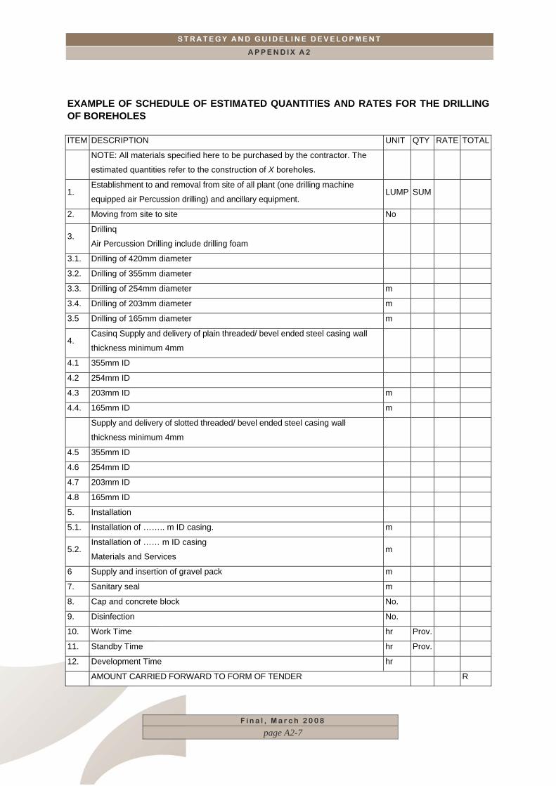
EXAMPLE OF SCHEDULE OF ESTIMATED QUANTITIES AND RATES FOR THE DRILLING OF BOREHOLES ITEM DESCRIPTION UNIT QTY RATE TOTAL
NOTE: All materials specified here to be purchased by the contractor. The
estimated quantities refer to the construction of X boreholes.
1. Establishment to and removal from site of all plant (one drilling machine
equipped air Percussion drilling) and ancillary equipment. LUMP SUM
2. Moving from site to site No
3. Drillinq
Air Percussion Drilling include drilling foam
3.1. Drilling of 420mm diameter
3.2. Drilling of 355mm diameter
3.3. Drilling of 254mm diameter m
3.4. Drilling of 203mm diameter m
3.5 Drilling of 165mm diameter m
4. Casinq Supply and delivery of plain threaded/ bevel ended steel casing wall
thickness minimum 4mm
4.1 355mm ID
4.2 254mm ID
4.3 203mm ID m
4.4. 165mm ID m
Supply and delivery of slotted threaded/ bevel ended steel casing wall
thickness minimum 4mm
4.5 355mm ID
4.6 254mm ID
4.7 203mm ID
4.8 165mm ID
5. Installation
5.1. Installation of …….. m ID casing. m
5.2. Installation of …… m ID casing
Materials and Services m
6 Supply and insertion of gravel pack m
7. Sanitary seal m
8. Cap and concrete block No.
9. Disinfection No.
10. Work Time hr Prov.
11. Standby Time hr Prov.
12. Development Time hr
AMOUNT CARRIED FORWARD TO FORM OF TENDER R


S T R A T E G Y A N D G U I D E L I N E D E V E L O P M E N T
A P P E N D I X B
F i n a l , M a r c h 2 0 0 8
page i
CCOONNTTEENNTTSS
APPENDIX B. INFORMATION TO BE RECORDED__________________ 1

S T R A T E G Y A N D G U I D E L I N E D E V E L O P M E N T
A P P E N D I X B
APPENDIX B. INFORMATION TO BE RECORDED
NGA GROUNDWATER HYDROCENSUS FORMAll colored fields are mandatory.* Notes and/or Tips are indicated with an asterisk (*).
1 Ownership Date(ccyy-mm-dd)
2 Owner Surname
3 Owner Initials
4 Address Location Home5 Address Type Postal Physical6 Address Text
7 Suburb
8 Town/City
9 Postal Code
10 Address Location Business11 Address Type Postal Physical12 Building Name
13 Office Number
14 Street Name and Number
15 Suburb
16 Town/City
17 Postal Code
18 Telephone Number Location Business Home
Switchboard Fax Cellular Land Line
20 Dialling code
21 Telephone Number
22 Extension
19
Owner Information
Telephone Number Type
Business Address
Home Address
F i n a l , M a r c h 2 0 0 8
page B-1
S T R A T E G Y A N D G U I D E L I N E D E V E L O P M E N T
A P P E N D I X B
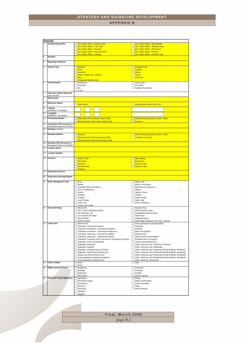
Geo, Water Affairs - Eastern Cape Geo, Water Affairs - MpumalangaGeo, Water Affairs - Free State Geo, Water Affairs - Northern CapeGeo, Water Affairs - Gauteng Geo, Water Affairs - North WestGeo, Water Affairs - Kwazulu Natal Geo, Water Affairs - PretoriaGeo, Water Affairs - Limpopo Geo, Water Affairs - Western Cape
2 Identifier
3 Reporting Institution
Borehole Seepage PondDrain SinkholeDug Well Spring Lateral / Radial Arm Collector TunnelMine Well PointProspective Borehole Site Abandoned InaccessibleDestroyed Not DrilledDry Standby (Production)In Use
6 Date when Status Observed(ccyy-mm-dd)
7 Map Number
8 Reference DatumCape Datum Hartbeeshoek Datum (WGS 84)
9 Latitude (DDMMSS / DD.ddddd )
10 Longitude (DDMMSS / DD.ddddd )
Differential GPS with Base Station (GB1) Global Positioning System (Hand - Held)Differential GPS without Base Station (GB) Surveyed
12 Coordinate GPS Accuracy (m)Estimated Position Error (EPE)
13 Elevation (mamsl)
Altimeter Global Positioning System (Hand - Held)Differential GPS with Base Station (GB1) Levelled or SurveyedDifferential GPS without Base Station (GB)
15 Elevation GPS Accuracy (m)Estimated Position Error (EPE)
16 Location Name
17 Location Number
Eastern Cape Mpumalanga Free State North WestGauteng Northern CapeKwazulu Natal Western Cape Limpopo
19 Registration District
20 Quaternary Drainage Region
Berg Middle VaalBreede Mvoti to UmzimkuluCrocodile (West) and Marico Mzimvubu to KeiskammaFish to Tsitsikamma OlifantsGouritz Olifants / DoornInkomati ThukelaLimpopo Upper OrangeLower Orange Upper VaalLower Vaal Usutu to MhlatuzeLuvubu and LetabaAlluvial Fan Riparian ZoneFlat / Gently Undulating Surface Steep Mountain Slope Hill / Mountain Top Unvegetated Shifting DunesLow Gradient Hill Slope Valley FloorNear Sinkhole Vegetated DunesRaised Terrace Water Body (Wetlands, Pan, River, Spring)Barren Rock Forest plantations (Indicate Wattle) Cultivated: Commercial Dryland GrasslandCultivated: Permanent – Commercial Irrigated HerblandCultivated: Permanent – Commercial Sugarcane Mines and QuarriesCultivated: Temporary - Commercial Irrigated Natural Forest Cultivated: Temporary – Commercial Dryland Natural Forest and Woodland Cultivated: Temporary Semi-Commercial / Subsistence Dryland Shrubland and Low Fynbos Degraded: Forest and Woodland Thicket and Bushland (etc.) Degraded: Grassland Urban / Built-Up Land: Industrial / Transport Degraded: Herbland Urban / Built-Up Land: Residential Degraded: Shrubland and Low Fynbos Urban / Built-Up Land: Residential (Small Holdings: Bushland) Degraded: Thicket and Bushland (etc.) Urban / Built-Up Land: Residential (Small Holdings: Grassland) Dongas and Sheet Erosion Scars Urban / Built-Up Land: Residential (Small Holdings: Shrubland) Forest plantations (Indicate Eucalyptus) Urban / Built-Up Land: Residential (Small Holdings: Woodland)Forest plantations (Indicate Pine) Urban / Built-Up: CommercialBrack SaltyFreshDewatering ProductionDrainage RechargeExploration StandbyObservation Waste DisposalAgriculture MiningBulk Water Supply Nature ConservationCommercial Power Generation Domestic Public Gardening Stock WateringIndustrial Irrigation
4 Geosite Type
14
Geosite Status5
1
Land cover
26 Observed / Actual Water Use
Geomorphology22
24
23
DWAF Geosite Purpose 25
Geohydrology Office
Elevation Method
Taste of Water
Water Management Area21
18
Geosite
Coordinate Method11
Province
F i n a l , M a r c h 2 0 0 8
page B-2
S T R A T E G Y A N D G U I D E L I N E D E V E L O P M E N T
A P P E N D I X B
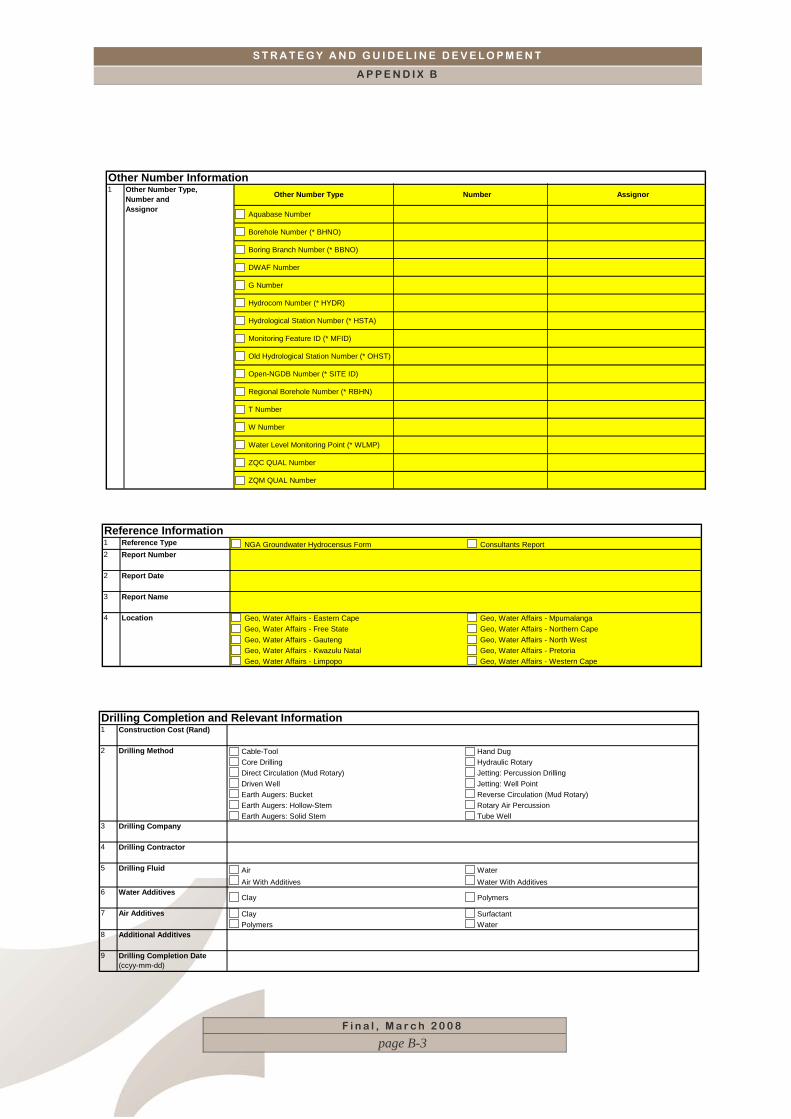
Aquabase Number
Borehole Number (* BHNO)
Boring Branch Number (* BBNO)
DWAF Number
G Number
Hydrocom Number (* HYDR)
Hydrological Station Number (* HSTA)
Monitoring Feature ID (* MFID)
Old Hydrological Station Number (* OHST)
Open-NGDB Number (* SITE ID)
Regional Borehole Number (* RBHN)
T Number
W Number
Water Level Monitoring Point (* WLMP)
ZQC QUAL Number
ZQM QUAL Number
Other Number Information Other Number Type Number AssignorOther Number Type,
Number andAssignor
1
1 Reference Type NGA Groundwater Hydrocensus Form Consultants Report2 Report Number
2 Report Date
3 Report Name
Geo, Water Affairs - Eastern Cape Geo, Water Affairs - MpumalangaGeo, Water Affairs - Free State Geo, Water Affairs - Northern CapeGeo, Water Affairs - Gauteng Geo, Water Affairs - North WestGeo, Water Affairs - Kwazulu Natal Geo, Water Affairs - PretoriaGeo, Water Affairs - Limpopo Geo, Water Affairs - Western Cape
Location4
Reference Information
1 Construction Cost (Rand)
Cable-Tool Hand DugCore Drilling Hydraulic Rotary Direct Circulation (Mud Rotary) Jetting: Percussion Drilling Driven Well Jetting: Well Point Earth Augers: Bucket Reverse Circulation (Mud Rotary) Earth Augers: Hollow-Stem Rotary Air Percussion Earth Augers: Solid Stem Tube Well
3 Drilling Company
4 Drilling Contractor
Air WaterAir With Additives Water With Additives
6 Water Additives Clay Polymers
Clay SurfactantPolymers Water
8 Additional Additives
9 Drilling Completion Date (ccyy-mm-dd)
Drilling Completion and Relevant Information
5
Drilling Method
7 Air Additives
Drilling Fluid
2
F i n a l , M a r c h 2 0 0 8
page B-3
S T R A T E G Y A N D G U I D E L I N E D E V E L O P M E N T
A P P E N D I X B
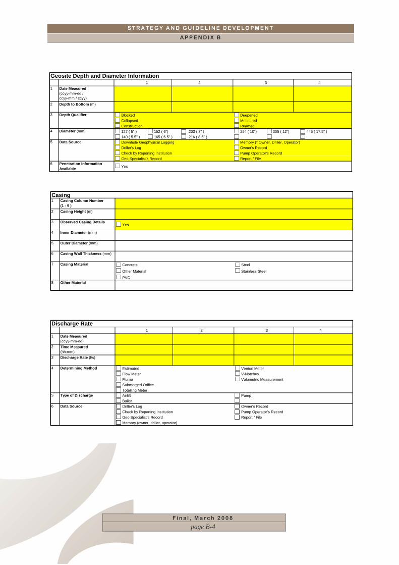
1 2 3 41 Date Measured
(ccyy-mm-dd / ccyy-mm / ccyy)
2 Depth to Bottom (m)
Blocked DeepenedCollapsed MeasuredConstruction Reamed127 ( 5" ) 152 ( 6") 203 ( 8" ) 254 ( 10") 305 ( 12") 445 ( 17.5" )140 ( 5.5" ) 165 ( 6.5" ) 216 ( 8.5" )Downhole Geophysical Logging Memory (* Owner, Driller, Operator)Driller's Log Owner's Record Check by Reporting Institution Pump Operator's Record Geo Specialist’s Record Report / File
6 Penetration Information Available Yes
Depth Qualifier3
Diameter (mm)
Geosite Depth and Diameter Information
Data Source
4
5
Casing1 Casing Column Number
(1 - 9 )2 Casing Height (m)
3 Observed Casing Details Yes
4 Inner Diameter (mm)
5 Outer Diameter (mm)
6 Casing Wall Thickness (mm)
Concrete Steel
Other Material Stainless Steel
PVC8 Other Material
Casing Material 7
1 2 3 41 Date Measured
(ccyy-mm-dd)2 Time Measured
(hh:mm)3 Discharge Rate (l/s)
Estimated Venturi MeterFlow Meter V-NotchesFlume Volumetric MeasurementSubmerged OrificeTotalling MeterAirlift PumpBailerDriller's Log Owner’s RecordCheck by Reporting Institution Pump Operator’s RecordGeo Specialist’s Record Report / FileMemory (owner, driller, operator)
Data Source
Discharge Rate
4 Determining Method
6
Type of Discharge5
F i n a l , M a r c h 2 0 0 8
page B-4
S T R A T E G Y A N D G U I D E L I N E D E V E L O P M E N T
A P P E N D I X B
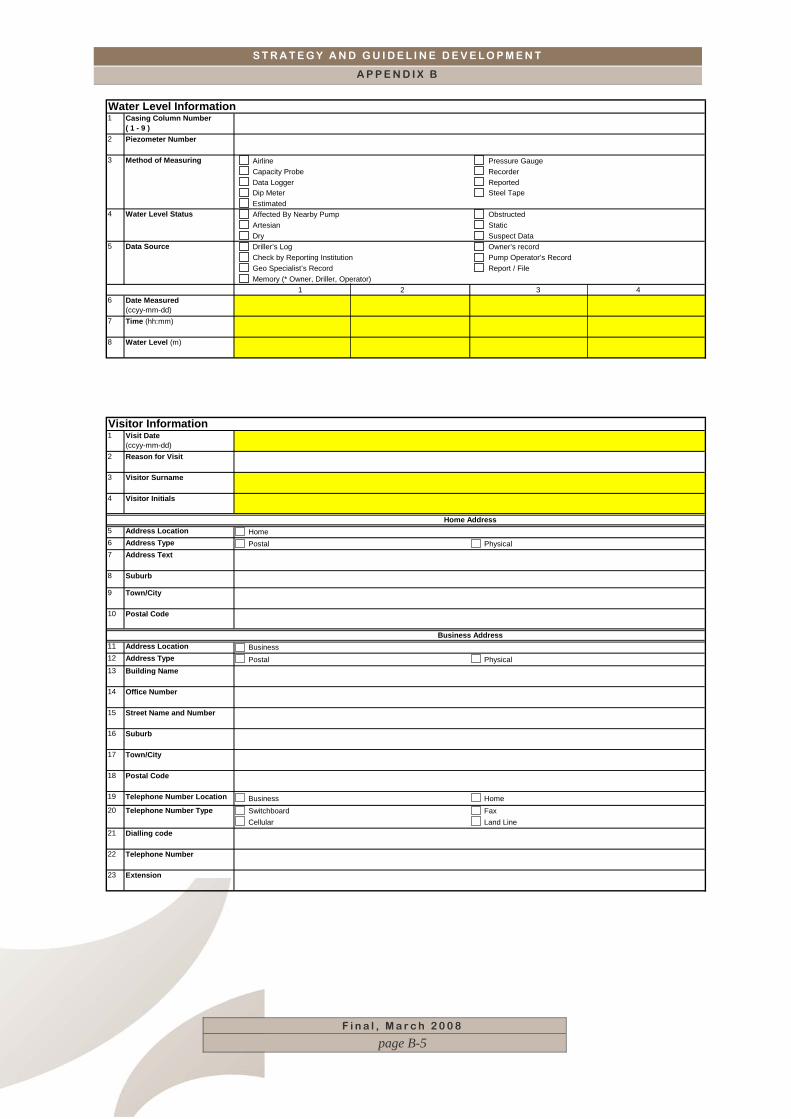
1 Casing Column Number( 1 - 9 )
2 Piezometer Number
Airline Pressure Gauge Capacity Probe Recorder Data Logger Reported Dip Meter Steel Tape Estimated Affected By Nearby Pump Obstructed Artesian Static Dry Suspect Data Driller’s Log Owner’s record Check by Reporting Institution Pump Operator’s Record Geo Specialist’s Record Report / File Memory (* Owner, Driller, Operator)
1 2 3 46 Date Measured
(ccyy-mm-dd)7 Time (hh:mm)
8 Water Level (m)
Method of Measuring
Data Source
3
5
Water Level Information
Water Level Status4
F i n a l , M a r c h 2 0 0 8
page B-5
1 Visit Date(ccyy-mm-dd)
2 Reason for Visit
3 Visitor Surname
4 Visitor Initials
5 Address Location Home6 Address Type Postal Physical7 Address Text
8 Suburb
9 Town/City
10 Postal Code
11 Address Location Business12 Address Type Postal Physical13 Building Name
14 Office Number
15 Street Name and Number
16 Suburb
17 Town/City
18 Postal Code
19 Telephone Number Location Business HomeSwitchboard Fax Cellular Land Line
21 Dialling code
22 Telephone Number
23 Extension
Visitor Information
Home Address
Business Address
20 Telephone Number Type
S T R A T E G Y A N D G U I D E L I N E D E V E L O P M E N T
A P P E N D I X B
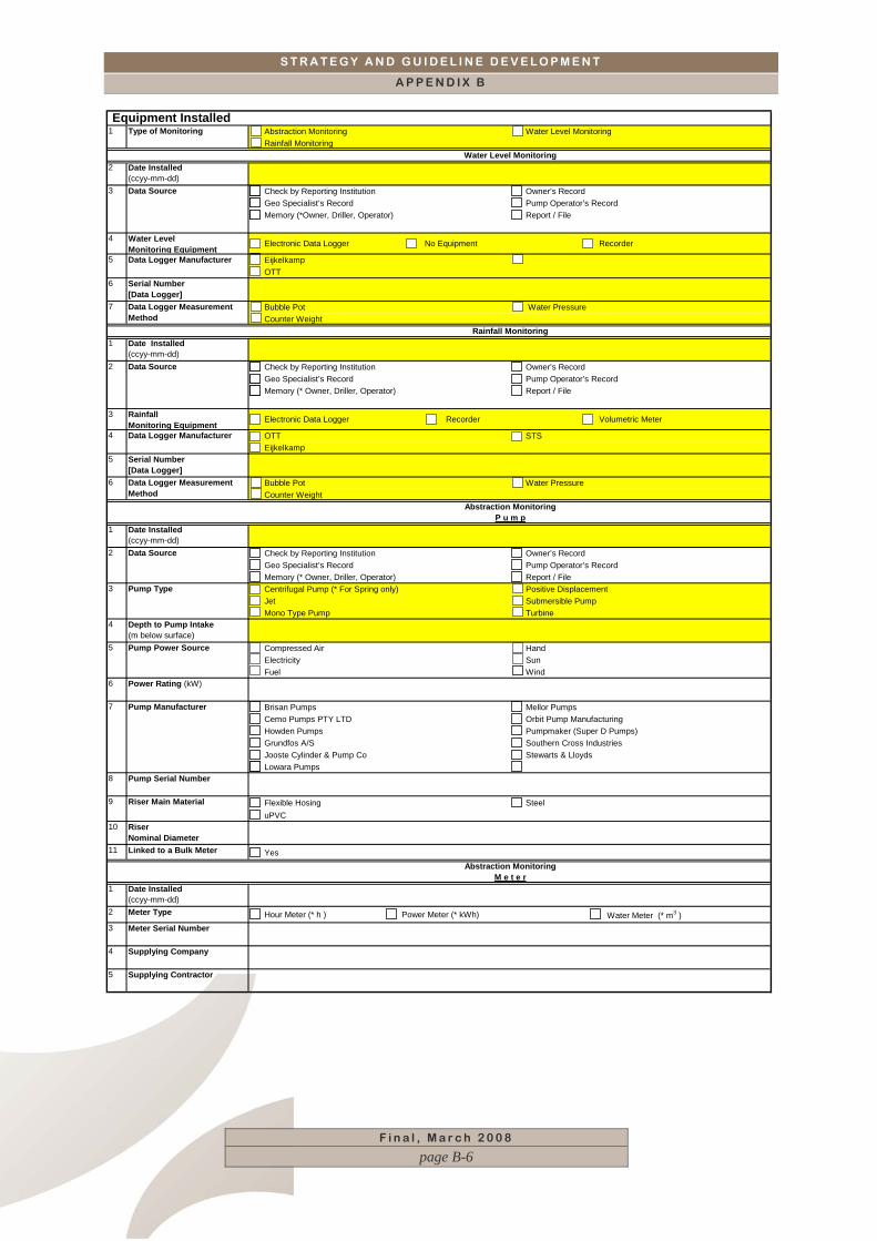
Abstraction Monitoring Water Level MonitoringRainfall Monitoring
2 Date Installed(ccyy-mm-dd)
Check by Reporting Institution Owner’s RecordGeo Specialist’s Record Pump Operator’s RecordMemory (*Owner, Driller, Operator) Report / File
4 Water Level Monitorin
F i n a l , M a r c h 2 0 0 8
page B-6
g Equipment Electronic Data Logger No Equipment Recorder
EijkelkampOTT
6 Serial Number [Data Logger]
Bubble Pot Water PressureCounter Weight
1 Date Installed(ccyy-mm-dd)
Check by Reporting Institution Owner’s RecordGeo Specialist’s Record Pump Operator’s RecordMemory (* Owner, Driller, Operator) Report / File
3 Rainfall Monitoring Equipment
Electronic Data Logger Recorder Volumetric Meter
OTT STSEijkelkamp
5 Serial Number [Data Logger]
Bubble Pot Water PressureCounter Weight
1 Date Installed(ccyy-mm-dd)
Check by Reporting Institution Owner’s RecordGeo Specialist’s Record Pump Operator’s RecordMemory (* Owner, Driller, Operator) Report / FileCentrifugal Pump (* For Spring only) Positive DisplacementJet Submersible PumpMono Type Pump Turbine
4 Depth to Pump Intake (m below surface)
Compressed Air HandElectricity SunFuel Wind
6 Power Rating (kW)
Brisan Pumps Mellor PumpsCemo Pumps PTY LTD Orbit Pump ManufacturingHowden Pumps Pumpmaker (Super D Pumps)Grundfos A/S Southern Cross IndustriesJooste Cylinder & Pump Co Stewarts & LloydsLowara Pumps
8 Pump Serial Number
Flexible Hosing SteeluPVC
10 Riser Nominal Diameter
11 Linked to a Bulk Meter Yes
1 Date Installed(ccyy-mm-dd)
2 Meter Type Hour Meter (* h ) Power Meter (* kWh) Water Meter (* m3 )3 Meter Serial Number
4 Supplying Company
5 Supplying Contractor
Equipment Installed
Water Level Monitoring
3 Data Source
Type of Monitoring
Rainfall Monitoring
9 Riser Main Material
7
Pump Power Source
Abstraction MonitoringP u m p
Data Source
3 Pump Type
5
Pump Manufacturer
6 Data Logger MeasurementMethod
5
1
Data Source2
Data Logger Manufacturer
7
4 Data Logger Manufacturer
Data Logger MeasurementMethod
2
Abstraction MonitoringM e t e r
S T R A T E G Y A N D G U I D E L I N E D E V E L O P M E N T
A P P E N D I X B
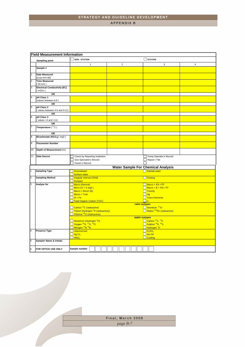
Sampling point NON - STATION STATION
1 2 3 4Sample #
1 Date Measured(ccyy-mm-dd)
2 Time Measured( hh:mm )
3 Electrical Conductivity (EC) ( mS/m )
OR4 pH Class 1
(values between 6-9 )OR
5 pH Class 2 ( values between 4-6 and 9-11)
OR6 pH Class 3
( values <4 and >11)OR
7 Temperature ( 0 C )
OR8 Bicarbonate (HCO3) ( mg/l )
9 Piezometer Number
10 Depth of Measurement (m)
Check by Reporting Institution Pump Operator’s RecordGeo Specialist’s Record Report / FileOwner’s Record
Field Measurement Information
11 Data Source
Groundwater Rainfall waterSurface waterIrregular Interval GRAB FlowingPumpedMacro (Normal) Macro + KN +TPMicro (Cl < 5 mg/l ) Macro + B + KN +TPMacro + Boron (B) ToxicityMacro + Turb HgAl + Fe Trace ElementsTotal Organic Carbon (TOC) Li
Carbon 14C (radioactive) Strontium 87SrTritium (Hydrogen 3H (radioactive)) Radon 222Rn (radioactive)Chlorine 36Cl (radioactive)
Deuterium (Hydrogen 2H) Carbon 12C, 13COxygen 16O, 17O, 18O Sulphur 32S, 34SNitrogen 14N 15N Hydrogen 1HUnpreserved H2SO4
Hg Cl2 Na OHHNO3 Cooling
5 Sampler Name & Initials
6 FOR OFFICE USE ONLY
Preserve Type
Analyse for
1 Sampling Type
4
Sample number
Water Sample For Chemical Analysis
radio isotopes
stable isotopes
3
2 Sampling Method
F i n a l , M a r c h 2 0 0 8
page B-7
S T R A T E G Y A N D G U I D E L I N E D E V E L O P M E N T
A P P E N D I X B
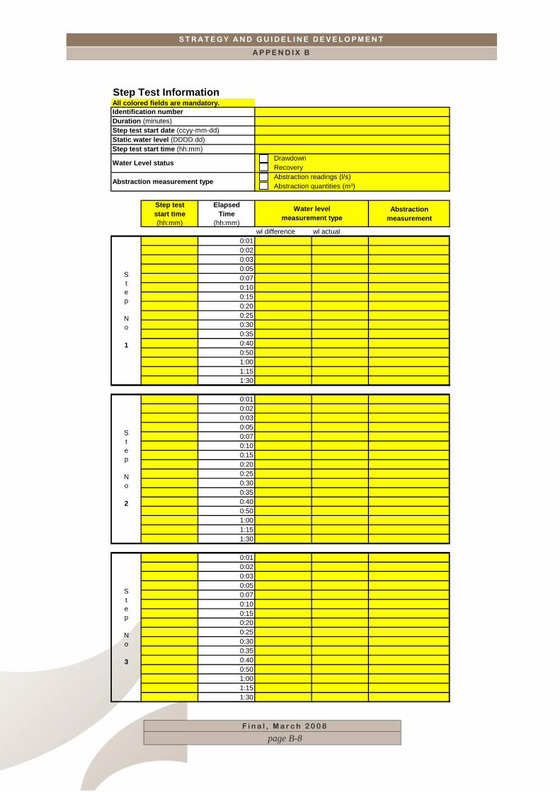
All colored fields are mandatory.
Step test start time (hh:mm)
Elapsed Time
(hh:mm)
Abstractionmeasurement
wl difference wl actual0:010:020:030:050:070:100:150:200:250:300:350:400:501:001:151:30
0:010:020:030:050:070:100:150:200:250:300:350:400:501:001:151:30
0:010:020:030:050:070:100:150:200:250:300:350:400:501:001:151:30
Step Test Information
Identification numberDuration (minutes)Step test start date (ccyy-mm-dd)Static water level (DDDD.dd)Step test start time (hh:mm)
Water Level status DrawdownRecovery
Abstraction measurement type Abstraction readings (l/s)Abstraction quantities (m³)
Step No 1
Step No 2
Step No 3
Water level measurement type
F i n a l , M a r c h 2 0 0 8
page B-8

S T R A T E G Y A N D G U I D E L I N E D E V E L O P M E N T
A P P E N D I X B
Multi-rate test start time (hh:mm)
Elapsed Time
(hh:mm)
Abstractionmeasurement
wl difference wl actual0:010:020:030:050:070:100:150:200:250:300:350:400:501:001:151:30
0:010:020:030:050:070:100:150:200:250:300:350:400:501:001:151:30
0:010:020:030:050:070:100:150:200:250:300:350:400:501:001:151:30
Multi-rate Test Information
Identification numberDuration (minutes)Multi-rate test start date (ccyy-mm-dd)Static water level (DDDD.dd)Multi-rate test start time (hh:mm)
Water Level status DrawdownRecovery
Abstraction measurement type Abstraction readings (l/s)Abstraction quantities (m³)
Step No 1
Water level measurement type
Step No 2
Step No 3
F i n a l , M a r c h 2 0 0 8
page B-9

S T R A T E G Y A N D G U I D E L I N E D E V E L O P M E N T
A P P E N D I X B
Constant yield test start time
(hh:mm)
Elapsed Time
(hh:mm)
Abstractionmeasurement
wl difference wl actual0:010:020:030:050:070:100:150:200:250:300:350:400:501:001:151:302:002:303:003:304:005:006:007:309:00
10:3012:0014:0016:0018:3021:0024:00
DRAWDOWN
Constant yield test start time (hh:mm)
Abstraction measurement typeAbstraction readings (l/s)Abstraction quantities (m³)
Constant yield test start date (ccyy-mm-dd)Static water level (DDDD.dd)
Constant Yield Test Information
Identification numberDuration (minutes)
Water level measurement type
F i n a l , M a r c h 2 0 0 8
page B-10

S T R A T E G Y A N D G U I D E L I N E D E V E L O P M E N T
A P P E N D I X B
F i n a l , M a r c h 2 0 0 8
page B-11
S T R A T E G Y A N D G U I D E L I N E D E V E L O P M E N T
A P P E N D I X C
F i n a l , M a r c h 2 0 0 8
page i
CCOONNTTEENNTTSS LIST OF FIGURES _________________________________________________________ ii LIST OF TABLES __________________________________________________________ ii
APPENDIX C. TECHNICAL GUIDELINES AND PROCEDURES FOR THE DRILLING, TESTING AND SAMPLING OF BOREHOLES_ 1
C.1 Introduction 1 C.2 Final design of boreholes 1
C.2.1 Borehole Design 2 C.2.2 Technical Specifications 2 C.2.3 Drilling Diameters 2 C.2.4 Reaming 2 C.2.5 Casing 2 C.2.6 Formation Stabiliser 3 C.2.7 Sanitary Seal 3 C.2.8 Borehole Verticality and Straightness 3 C.2.9 Unsuccessful Boreholes 3 C.2.10 Drilling Techniques 4 C.2.11 Develop boreholes 5 C.2.12 Disinfect boreholes 7 C.2.13 Borehole surface works 8 C.2.14 Borehole identification 10 C.2.15 Site cleaning 10 C.2.16 Further Information 10
C.3 Pumping Tests 10 C.3.1 Step Drawdown Test 11 C.3.2 Constant Discharge Test 11 C.3.3 Recovery Test 12 C.3.4 Measurement Guidelines 12 C.3.5 Test Continuity 16 C.3.6 Further Information 16
C.4 Water sampling and quality 16 C.5 Rehabilitation of boreholes 17

S T R A T E G Y A N D G U I D E L I N E D E V E L O P M E N T
A P P E N D I X C
F i n a l , M a r c h 2 0 0 8
page ii
LLIISSTT OOFF FFIIGGUURREESS Figure C.1: Sealing of boreholes_____________________________________________ 4 Figure C.2: Typical jetting tool_______________________________________________ 6 Figure C.3: Typical surging block ____________________________________________ 7 Figure C.4: Typical concrete slab detail _______________________________________ 8 Figure C.5: Cap and double locking nut system _________________________________ 9 Figure C.6: Welding of steel plate ____________________________________________ 9 Figure C.7: Typical details of a rectangular V-notch weir _________________________ 13 Figure C.8: Typical details of the installation of a PVC/polyethylene piezometer and flow
meter _______________________________________________________ 15
LLIISSTT OOFF TTAABBLLEESS Table C.1: Recommended injection quantities for borehole disinfection ______________ 8 Table C.2: Pumping tests and durations for various sectors (after SABS 1996) _______ 11 Table C.3: Guidelines on container size per borehole yield range__________________ 12 Table C.4: Calibration details for a rectangular V notch weir ______________________ 13 Table C.5: Flow rates through circular orifice weirs (after Driscoll 1986)_____________ 14

S T R A T E G Y A N D G U I D E L I N E D E V E L O P M E N T
A P P E N D I X C
F i n a l , M a r c h 2 0 0 8
page C-1
APPENDIX C. TECHNICAL GUIDELINES AND PROCEDURES FOR THE DRILLING, TESTING AND SAMPLING OF BOREHOLES
C.1 Introduction This sections details the technical considerations the Water Manager needs to apply when designing and implementing assessment, planning and management programmes for groundwater resources. This section covers the siting, drilling testing and sampling procedures that need to be followed to ensure the implementation of a successful programme. For further information concerning these aspects refer to the Toolkit for Water Services developed by DWAF and NORAD in 2004.
C.2 Final design of boreholes Boreholes provide a means of exploring, quantifying, accessing and tapping groundwater resources. They are used for many purposes including:
Exploration (assessment),
Water supply,
Monitoring,
Dewatering, and
Artificial recharge.
Boreholes serve as a means of obtaining invaluable subsurface geological and hydrogeological data. Information that can be obtained from drilling includes:
Geology (granite, dolomite, chert, dolerite, etc),
Weathering profile,
Position of water bearing and non-water bearing zones,
Position of (potential) aquifer(s) within the profile,
Water strike(s),
Blowing yield, (from air percussion drilling),
Hydraulic parameters, etc.
It is therefore important that boreholes are sited and drilled, pump-tested and equipped according to the set of minimum requirements as set out in this guideline. Application of these minimum
S T R A T E G Y A N D G U I D E L I N E D E V E L O P M E N T
A P P E N D I X C
F i n a l , M a r c h 2 0 0 8
page C-2
requirements to boreholes drilled for whatever purpose during the assessment phase will ensure the preservation of the natural quality of the groundwater resource being investigated by preventing contaminated water from entering the resource.
C.2.1 Borehole Design The Hydrogeologist will undertake the final design of each individual borehole while on site during the drilling process. Upfront planning and preparation by the Hydrogeologist is however required to ensure that sufficient and correct materials are available on site to allow the completion of each borehole immediately following the drilling of the hole.
C.2.2 Technical Specifications The Hydrogeologist and Drilling Contractor should ensure that drilling is undertaken according to the technical specifications forming part of the drilling tender. A generic technical specification suitable for drilling of boreholes is included in Appendix A.1.
C.2.3 Drilling Diameters The diameter of boreholes that are drilled and completed must be compatible with the expected condition of the groundwater resource (formation, weathering, fracturing etc.), anticipated final borehole depth, and type of borehole (exploration, monitoring, production). Starting diameters will be between 8” to 15” (200mm to 380mm) or more, depending upon the anticipated drilling depth and final diameter. Completed diameters vary between 6" to 10" (152 mm to 254 mm) depending on use, anticipated yield and size of the production pump.
C.2.4 Reaming Reaming involves enlarging the initial drill hole to a larger diameter through unstable material, including the overburden and any collapsing formation encountered at depth, to allow insertion of casing.
C.2.5 Casing Casing (or borehole lining) is required to ensure the long term stability of the borehole. The function of the casing is to support unstable material from collapsing into the borehole during and after drilling. Where casing is required below the water strike level to prevent unstable water bearing zones from collapsing, the casing must be slotted to allow inflow of the water intersected. All steel casing should have a minimum wall thickness of 4mm and should be approximately 60mm less in diameter than the drilled hole.
S T R A T E G Y A N D G U I D E L I N E D E V E L O P M E N T
A P P E N D I X C
F i n a l , M a r c h 2 0 0 8
page C-3
Steel casing with a minimum wall thickness of 4mm should be used in unstable conditions. Plastic or uPVC casings are not suitable since casings made from these materials cannot be pushed past collapsing horizons.
C.2.6 Formation Stabiliser Formation stabiliser (sometimes referred to as gravel pack) is placed in the annular space between the slotted casing and the borehole sidewall to provide a permeable zone between the geological formation and the casing, while at the same time protecting the slotted casing from clogging due to the collapse of the formation. The formation stabiliser must comprise well sorted, sub-rounded quartzite or similar rock. The smallest grain size must be larger than the casing perforations/slots. The formation stabiliser should extend a minimum of 10m above the top of the uppermost perforated/slotted section of casing before the borehole is developed. Drilling cuttings removed from the borehole must not be used as a formation stabiliser substitute, but can be used as backfill above the formation stabiliser.
C.2.7 Sanitary Seal The sanitary seal comprises a cement or cement-bentonite mix grout and extends to a depth of 3 - 6m below ground surface. A sanitary seal is installed to:
Prevent the inflow of potentially polluting surface water into the borehole via the annular space between the borehole sidewall and the outside of the casing, and
Provide surface stability to the casing.
Every borehole must be completed with a sanitary seal, irrespective of its use, .i.e, monitoring, exploratory, production, dewatering, etc., unless backfilled and sealed with a concrete plug.
C.2.8 Borehole Verticality and Straightness It is important that boreholes are both vertical and straight to allow for trouble free installation and operation of the production pump. The technical specifications in Appendix A.1 detail the tests that the Drilling Contractor may be requested to carry out to confirm the borehole verticality and straightness. The Hydrogeologist should confirm these tests on site.
C.2.9 Unsuccessful Boreholes Unsuccessful, abandoned or lost boreholes must be correctly plugged for safety and to protect the aquifer against pollution. Such boreholes must be backfilled to the surface with the drilling
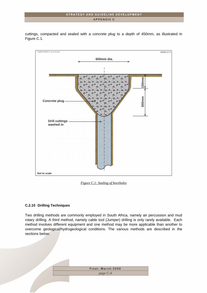
S T R A T E G Y A N D G U I D E L I N E D E V E L O P M E N T
A P P E N D I X C
cuttings, compacted and sealed with a concrete plug to a depth of 450mm, as illustrated in Figure C.1.
600mm dia.
Concrete plug
Drill cuttingswashed in
150m
m30
0mm
Not to scale
Figure C.1: Sealing of boreholes
C.2.10 Drilling Techniques Two drilling methods are commonly employed in South Africa, namely air percussion and mud rotary drilling. A third method, namely cable tool (Jumper) drilling is only rarely available. Each method involves different equipment and one method may be more applicable than another to overcome geological/hydrogeological conditions. The various methods are described in the sections below.
F i n a l , M a r c h 2 0 0 8
page C-4
S T R A T E G Y A N D G U I D E L I N E D E V E L O P M E N T
A P P E N D I X C
F i n a l , M a r c h 2 0 0 8
page C-5
Down-the-Hole Air percussion drilling This technique involves using compressed air to operate a pneumatic hammer and button bit to break up the formation as drilling advances. Air percussion drilling is suitable for the weathered and hard rock and is the most commonly used technique. Difficult drilling conditions encountered through collapsing ground, and other unstable or cavernous formations can be overcome by using the Oversize Diameter (ODEX) method. Mud rotary drilling This technique involves the continuous circulation of a viscous biodegradable drilling fluid within the borehole, which prevents caving of the borehole, removes drill cuttings and cleans the tricone bit. This technique can also be used for the drilling of unconsolidated or highly weathered formations but is not suitable for cavernous formations and very hard layers. Cable tool percussion drilling This technique involves the repeated lifting and dropping of a heavy string of drilling tools suspended at the end of a continuous cable. It is suitable for drilling in unconsolidated weathered and cavernous formations. Progress will be extremely slow in hard consolidated layers and its use has thus been superseded by the down-the-hole air percussion method. Cable tool rigs are currently normally utilised for the cleaning and rehabilitating of existing boreholes.
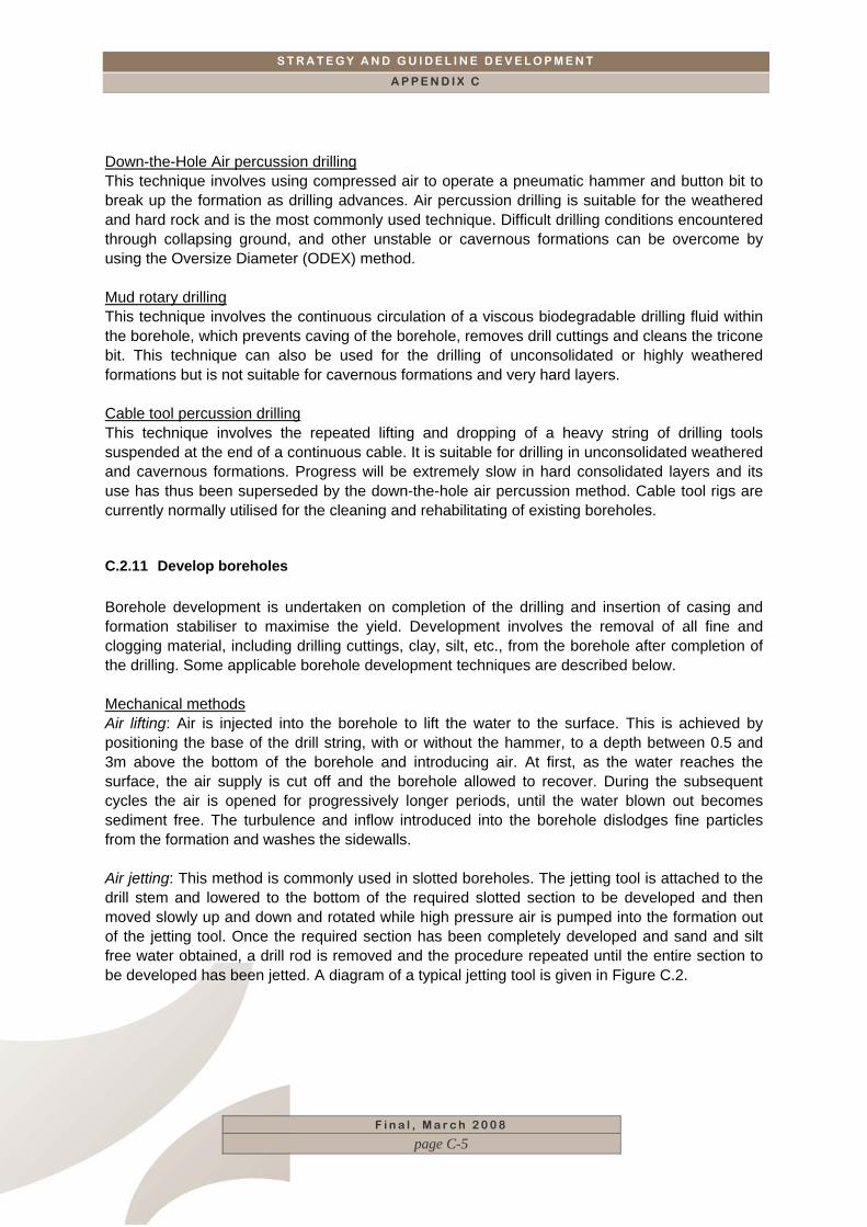
C.2.11 Develop boreholes Borehole development is undertaken on completion of the drilling and insertion of casing and formation stabiliser to maximise the yield. Development involves the removal of all fine and clogging material, including drilling cuttings, clay, silt, etc., from the borehole after completion of the drilling. Some applicable borehole development techniques are described below. Mechanical methods Air lifting: Air is injected into the borehole to lift the water to the surface. This is achieved by positioning the base of the drill string, with or without the hammer, to a depth between 0.5 and 3m above the bottom of the borehole and introducing air. At first, as the water reaches the surface, the air supply is cut off and the borehole allowed to recover. During the subsequent cycles the air is opened for progressively longer periods, until the water blown out becomes sediment free. The turbulence and inflow introduced into the borehole dislodges fine particles from the formation and washes the sidewalls. Air jetting: This method is commonly used in slotted boreholes. The jetting tool is attached to the drill stem and lowered to the bottom of the required slotted section to be developed and then moved slowly up and down and rotated while high pressure air is pumped into the formation out of the jetting tool. Once the required section has been completely developed and sand and silt free water obtained, a drill rod is removed and the procedure repeated until the entire section to be developed has been jetted. A diagram of a typical jetting tool is given in Figure C.2.
S T R A T E G Y A N D G U I D E L I N E D E V E L O P M E N T
A P P E N D I X C
PLAN VIEW
CROSS-SECTIONAL VIEW
Not to scale
Size of nozzle+_5mm
Welded spots
Diameter of tool to be
<10mm smaller than insidediameter of
screen/casing
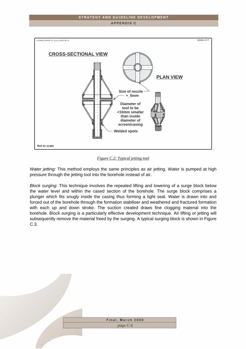
Figure C.2: Typical jetting tool Water jetting: This method employs the same principles as air jetting. Water is pumped at high pressure through the jetting tool into the borehole instead of air. Block surging: This technique involves the repeated lifting and lowering of a surge block below the water level and within the cased section of the borehole. The surge block comprises a plunger which fits snugly inside the casing thus forming a tight seal. Water is drawn into and forced out of the borehole through the formation stabiliser and weathered and fractured formation with each up and down stroke. The suction created draws fine clogging material into the borehole. Block surging is a particularly effective development technique. Air lifting or jetting will subsequently remove the material freed by the surging. A typical surging block is shown in Figure C.3.
F i n a l , M a r c h 2 0 0 8
page C-6
S T R A T E G Y A N D G U I D E L I N E D E V E L O P M E N T
A P P E N D I X C
Pipe
Pressure reliefhole
Rubber flap
Rubber disc
Steel orwooden disc
End plugNot to scale
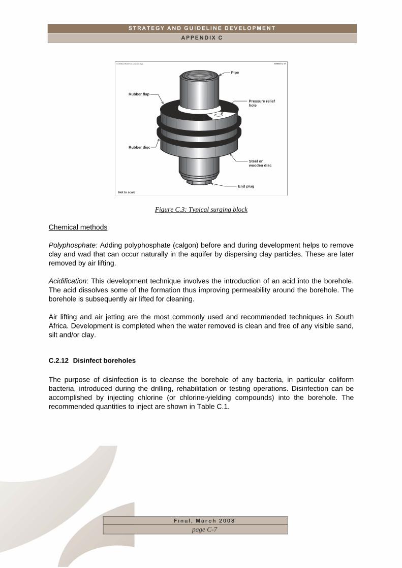
Figure C.3: Typical surging block
Chemical methods Polyphosphate: Adding polyphosphate (calgon) before and during development helps to remove clay and wad that can occur naturally in the aquifer by dispersing clay particles. These are later removed by air lifting. Acidification: This development technique involves the introduction of an acid into the borehole. The acid dissolves some of the formation thus improving permeability around the borehole. The borehole is subsequently air lifted for cleaning. Air lifting and air jetting are the most commonly used and recommended techniques in South Africa. Development is completed when the water removed is clean and free of any visible sand, silt and/or clay.
C.2.12 Disinfect boreholes The purpose of disinfection is to cleanse the borehole of any bacteria, in particular coliform bacteria, introduced during the drilling, rehabilitation or testing operations. Disinfection can be accomplished by injecting chlorine (or chlorine-yielding compounds) into the borehole. The recommended quantities to inject are shown in Table C.1.
F i n a l , M a r c h 2 0 0 8
page C-7
S T R A T E G Y A N D G U I D E L I N E D E V E L O P M E N T
A P P E N D I X C
Table C.1: Recommended injection quantities for borehole disinfection
Volume/weight of sterilant to be used for disinfection per unit
volume of water below groundwater test level Nominal
diameter of borehole
Volume of water (l) per metre of
borehole Sodium Hypochlorite Calcium Hypochlorite
Chlorinated lime
152 mm 18I 500 ml (2 cups) 26 g (¼ cup) 90g (1 cup) 165 mm 21I 600 ml (2½ cups) 30 g (½ cup) 105g (1 cup) 203 mm 33I 940 ml (4 cups) 47g (½ cup) 165g (1½ cups) 254 mm 51I 1500 ml (6 cups) 73g (¾ cup) 255g (2½ cups)
NOTES: 1. No distinction is made between open and cased portions of a borehole since these differences are
considered to have a negligible impact on calculated unit volumes. 2. The trade percentage of chlorine in the listed sterilants is taken to be: 3.5 percent by volume (35ml/l) for sodium hypochiorite 70 percent bt weight (700g/kg) for calcium hypochiorite 20 percent by weight (200g/kg) for chlorinated lime.
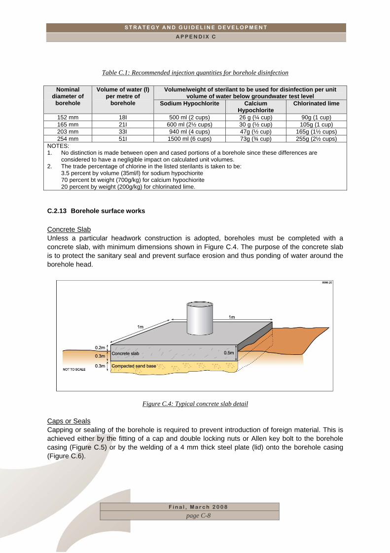
C.2.13 Borehole surface works Concrete Slab Unless a particular headwork construction is adopted, boreholes must be completed with a concrete slab, with minimum dimensions shown in Figure C.4. The purpose of the concrete slab is to protect the sanitary seal and prevent surface erosion and thus ponding of water around the borehole head.
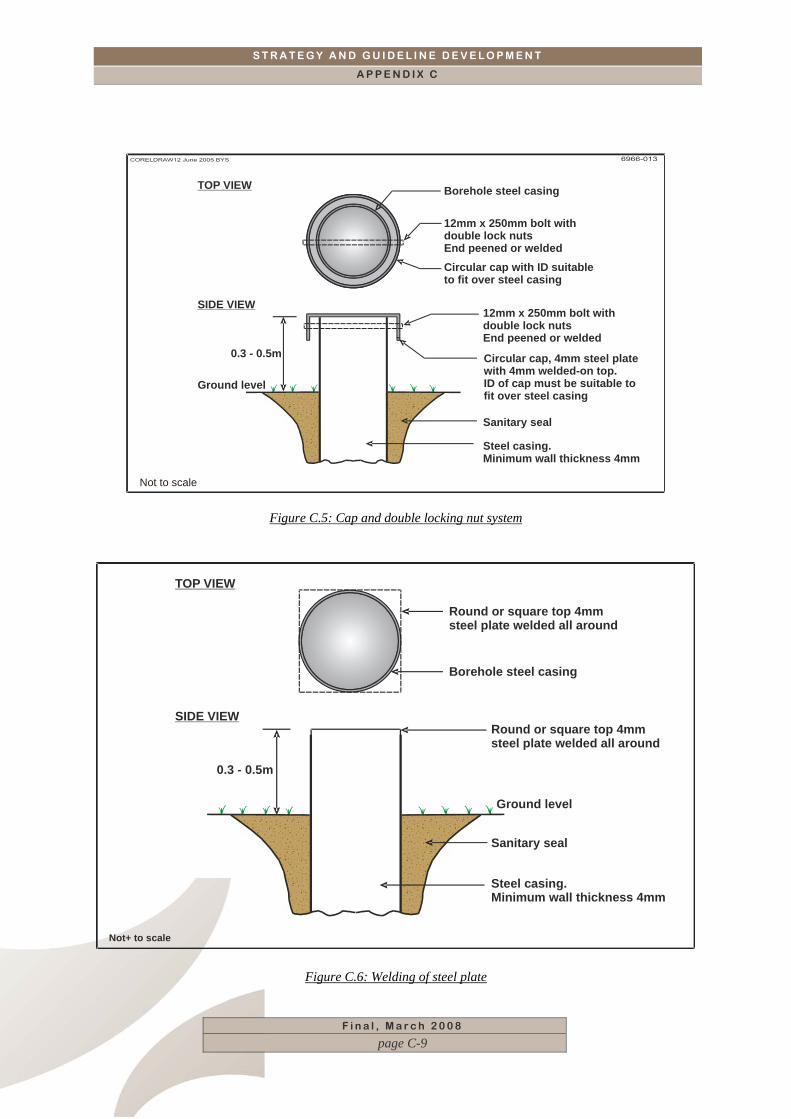
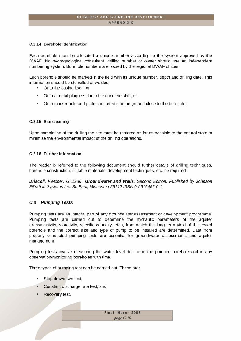
Figure C.4: Typical concrete slab detail Caps or Seals Capping or sealing of the borehole is required to prevent introduction of foreign material. This is achieved either by the fitting of a cap and double locking nuts or Allen key bolt to the borehole casing (Figure C.5) or by the welding of a 4 mm thick steel plate (lid) onto the borehole casing (Figure C.6).
F i n a l , M a r c h 2 0 0 8
page C-8
S T R A T E G Y A N D G U I D E L I N E D E V E L O P M E N T
A P P E N D I X C
Borehole steel casing
12mm x 250mm bolt withdouble lock nutsEnd peened or welded
12mm x 250mm bolt withdouble lock nutsEnd peened or welded
Sanitary seal
Steel casing.Minimum wall thickness 4mm
Ground level
0.3 - 0.5m
TOP VIEW
SIDE VIEW
Circular cap with ID suitableto fit over steel casing
Circular cap, 4mm steel platewith 4mm welded-on top.ID of cap must be suitable tofit over steel casing
Not to scale
Figure C.5: Cap and double locking nut system
F i n a l , M a r c h 2 0 0 8
page C-9
Round or square top 4mmsteel plate welded all around
Round or square top 4mmsteel plate welded all around
Sanitary seal
Steel casing.Minimum wall thickness 4mm
Borehole steel casing
Ground level
0.3 - 0.5m
TOP VIEW
SIDE VIEW
Not+ to scale
Figure C.6: Welding of steel plate
S T R A T E G Y A N D G U I D E L I N E D E V E L O P M E N T
A P P E N D I X C
F i n a l , M a r c h 2 0 0 8
page C-10
C.2.14 Borehole identification Each borehole must be allocated a unique number according to the system approved by the DWAF. No hydrogeological consultant, drilling number or owner should use an independent numbering system. Borehole numbers are issued by the regional DWAF offices. Each borehole should be marked in the field with its unique number, depth and drilling date. This information should be stencilled or welded:
Onto the casing itself; or
Onto a metal plaque set into the concrete slab; or
On a marker pole and plate concreted into the ground close to the borehole.
C.2.15 Site cleaning Upon completion of the drilling the site must be restored as far as possible to the natural state to minimise the environmental impact of the drilling operations.
C.2.16 Further Information The reader is referred to the following document should further details of drilling techniques, borehole construction, suitable materials, development techniques, etc. be required: Driscoll, Fletcher. G.,1986 Groundwater and Wells. Second Edition. Published by Johnson Filtration Systems Inc. St. Paul, Minnestoa 55112 ISBN 0-9616456-0-1
C.3 Pumping Tests Pumping tests are an integral part of any groundwater assessment or development programme. Pumping tests are carried out to determine the hydraulic parameters of the aquifer (transmissivity, storativity, specific capacity, etc.), from which the long term yield of the tested borehole and the correct size and type of pump to be installed are determined. Data from properly conducted pumping tests are essential for groundwater assessments and aquifer management. Pumping tests involve measuring the water level decline in the pumped borehole and in any observation/monitoring boreholes with time. Three types of pumping test can be carried out. These are:
Step drawdown test,
Constant discharge rate test, and
Recovery test.
S T R A T E G Y A N D G U I D E L I N E D E V E L O P M E N T
A P P E N D I X C
F i n a l , M a r c h 2 0 0 8
page C-11
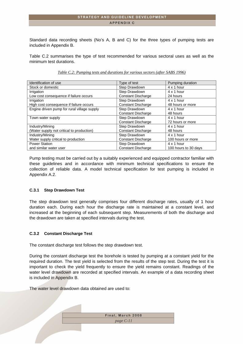
Standard data recording sheets (No’s A, B and C) for the three types of pumping tests are included in Appendix B. Table C.2 summarises the type of test recommended for various sectoral uses as well as the minimum test durations.
Table C.2: Pumping tests and durations for various sectors (after SABS 1996) Identification of use Type of test Pumping duration Stock or domestic Step Drawdown 4 x 1 hour Irrigation Low cost consequence if failure occurs
Step Drawdown Constant Discharge
4 x 1 hour 24 hours
Irrigation High cost consequence if failure occurs
Step Drawdown Constant Discharge
4 x 1 hour 48 hours or more
Engine driven pump for rural village supply Step Drawdown Constant Discharge
4 x 1 hour 48 hours
Town water supply Step Drawdown Constant Discharge
4 x 1 hour 72 hours or more
Industry/Mining (Water supply not critical to production)
Step Drawdown Constant Discharge
4 x 1 hour 48 hours
Industry/Mining Water supply critical to production
Step Drawdown Constant Discharge
4 x 1 hour 100 hours or more
Power Station and similar water user
Step Drawdown Constant Discharge
4 x 1 hour 100 hours to 30 days
Pump testing must be carried out by a suitably experienced and equipped contractor familiar with these guidelines and in accordance with minimum technical specifications to ensure the collection of reliable data. A model technical specification for test pumping is included in Appendix A.2.
C.3.1 Step Drawdown Test The step drawdown test generally comprises four different discharge rates, usually of 1 hour duration each. During each hour the discharge rate is maintained at a constant level, and increased at the beginning of each subsequent step. Measurements of both the discharge and the drawdown are taken at specified intervals during the test.
C.3.2 Constant Discharge Test The constant discharge test follows the step drawdown test. During the constant discharge test the borehole is tested by pumping at a constant yield for the required duration. The test yield is selected from the results of the step test. During the test it is important to check the yield frequently to ensure the yield remains constant. Readings of the water level drawdown are recorded at specified intervals. An example of a data recording sheet is included in Appendix B. The water level drawdown data obtained are used to:
S T R A T E G Y A N D G U I D E L I N E D E V E L O P M E N T
A P P E N D I X C
F i n a l , M a r c h 2 0 0 8
page C-12
Determine the hydraulic parameters of the aquifer, and
Assist in assessing the long term sustainable production yield of the tested borehole.
C.3.3 Recovery Test The recovery test involves recording the recovery of the water level in the pumped and any observation boreholes on completion of the constant rate test. Readings of the water level recovery commence immediately the pumping phase described in Section 2.3.2 is completed. Water level readings are recorded at specified intervals. An example of a data recording sheet is included in Appendix B. The water level recovery data obtained (often termed residual drawdown) are used to determine the hydraulic parameters of the aquifer and to assist in assessing the long term sustainable yield of the tested borehole.
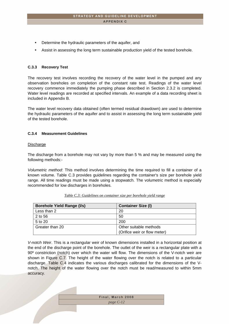
C.3.4 Measurement Guidelines Discharge The discharge from a borehole may not vary by more than 5 % and may be measured using the following methods:- Volumetric method: This method involves determining the time required to fill a container of a known volume. Table C.3 provides guidelines regarding the container's size per borehole yield range. All time readings must be made using a stopwatch. The volumetric method is especially recommended for low discharges in boreholes.
Table C.3: Guidelines on container size per borehole yield range
Borehole Yield Range (l/s) Container Size (l) Less than 2 20 2 to 56 50 5 to 20 200 Greater than 20 Other suitable methods
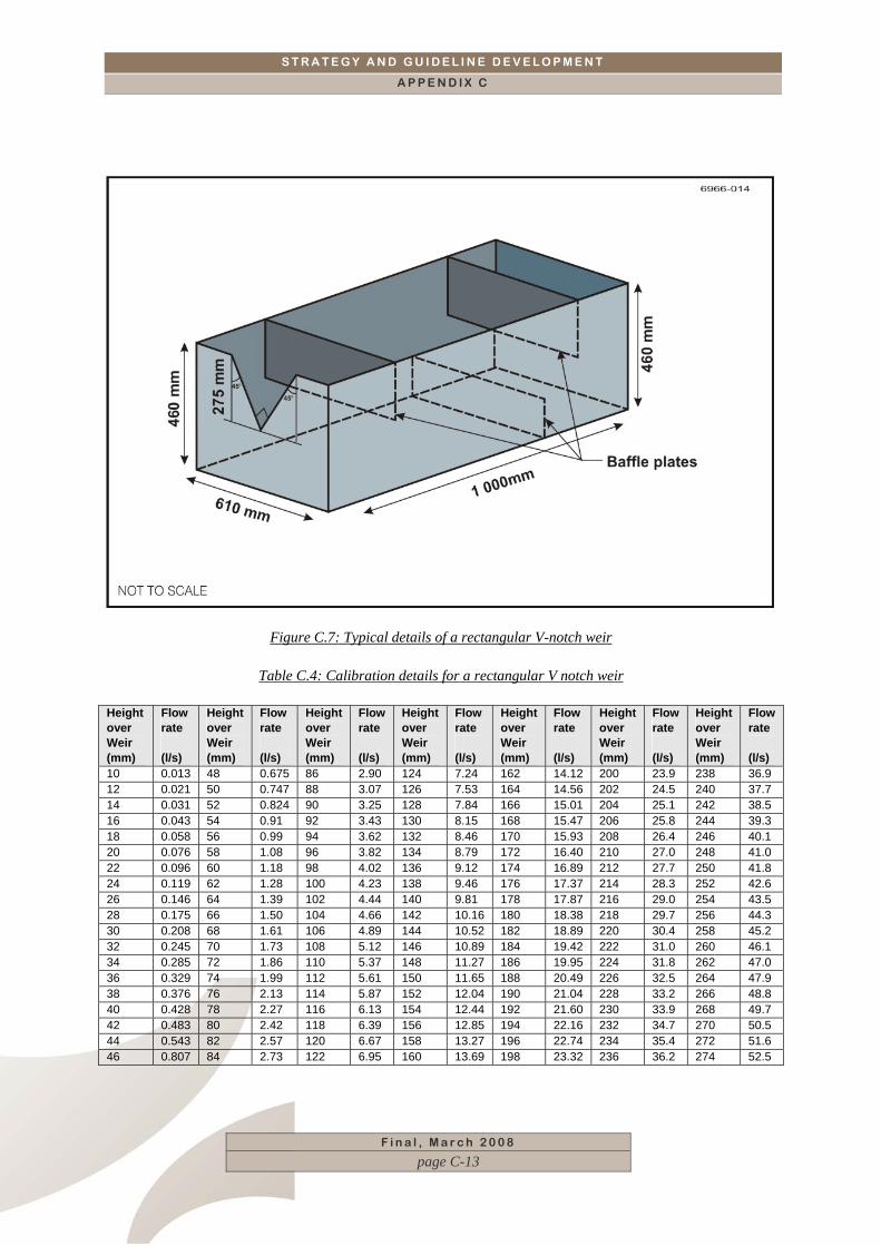
(Orifice weir or flow meter) V-notch Weir. This is a rectangular weir of known dimensions installed in a horizontal position at the end of the discharge point of the borehole. The outlet of the weir is a rectangular plate with a 90º constriction (notch) over which the water will flow. The dimensions of the V-notch weir are shown in Figure C.7. The height of the water flowing over the notch is related to a particular discharge. Table C.4 indicates the various discharges calibrated for the dimensions of the V-notch. The height of the water flowing over the notch must be read/measured to within 5mm accuracy.
S T R A T E G Y A N D G U I D E L I N E D E V E L O P M E N T
A P P E N D I X C
Figure C.7: Typical details of a rectangular V-notch weir
Table C.4: Calibration details for a rectangular V notch weir
Height over Weir (mm)
Flow rate (l/s)
Height over Weir (mm)
Flow rate (l/s)
Height over Weir (mm)
Flow rate (l/s)
Height over Weir (mm)
Flow rate (l/s)
Height over Weir (mm)
Flow rate (l/s)
Height over Weir (mm)
Flow rate (l/s)
Height over Weir (mm)
Flow rate (l/s)
10 0.013 48 0.675 86 2.90 124 7.24 162 14.12 200 23.9 238 36.9 12 0.021 50 0.747 88 3.07 126 7.53 164 14.56 202 24.5 240 37.7 14 0.031 52 0.824 90 3.25 128 7.84 166 15.01 204 25.1 242 38.5 16 0.043 54 0.91 92 3.43 130 8.15 168 15.47 206 25.8 244 39.3 18 0.058 56 0.99 94 3.62 132 8.46 170 15.93 208 26.4 246 40.1 20 0.076 58 1.08 96 3.82 134 8.79 172 16.40 210 27.0 248 41.0 22 0.096 60 1.18 98 4.02 136 9.12 174 16.89 212 27.7 250 41.8 24 0.119 62 1.28 100 4.23 138 9.46 176 17.37 214 28.3 252 42.6 26 0.146 64 1.39 102 4.44 140 9.81 178 17.87 216 29.0 254 43.5 28 0.175 66 1.50 104 4.66 142 10.16 180 18.38 218 29.7 256 44.3 30 0.208 68 1.61 106 4.89 144 10.52 182 18.89 220 30.4 258 45.2 32 0.245 70 1.73 108 5.12 146 10.89 184 19.42 222 31.0 260 46.1 34 0.285 72 1.86 110 5.37 148 11.27 186 19.95 224 31.8 262 47.0 36 0.329 74 1.99 112 5.61 150 11.65 188 20.49 226 32.5 264 47.9 38 0.376 76 2.13 114 5.87 152 12.04 190 21.04 228 33.2 266 48.8 40 0.428 78 2.27 116 6.13 154 12.44 192 21.60 230 33.9 268 49.7 42 0.483 80 2.42 118 6.39 156 12.85 194 22.16 232 34.7 270 50.5 44 0.543 82 2.57 120 6.67 158 13.27 196 22.74 234 35.4 272 51.6 46 0.807 84 2.73 122 6.95 160 13.69 198 23.32 236 36.2 274 52.5
F i n a l , M a r c h 2 0 0 8
page C-13
S T R A T E G Y A N D G U I D E L I N E D E V E L O P M E N T
A P P E N D I X C
F i n a l , M a r c h 2 0 0 8
page C-14
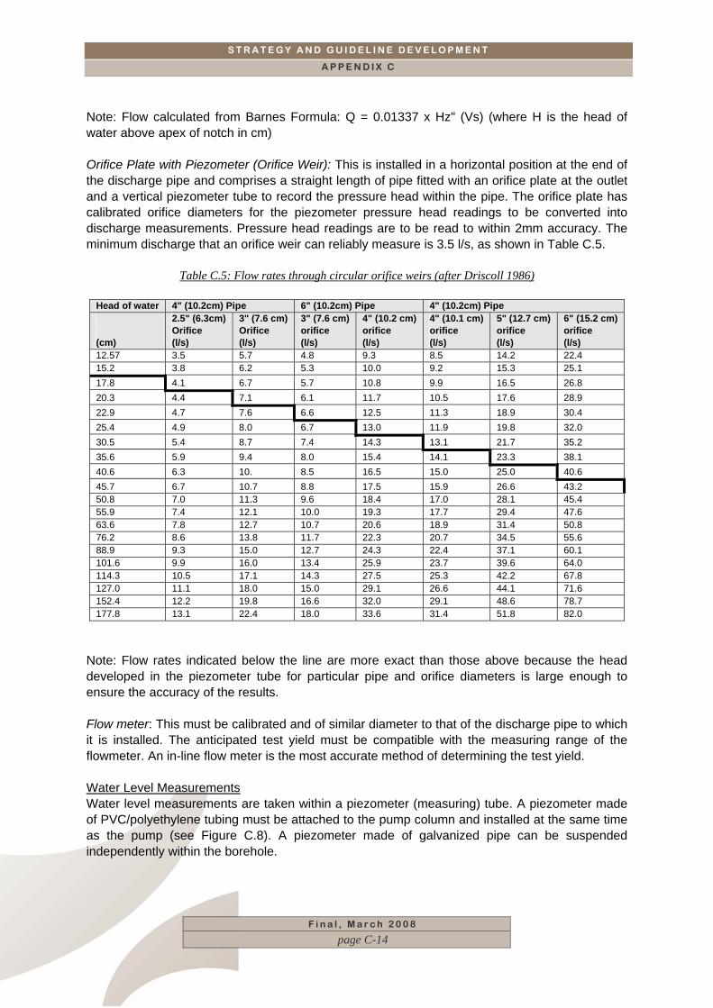
Note: Flow calculated from Barnes Formula: Q = 0.01337 x Hz" (Vs) (where H is the head of water above apex of notch in cm) Orifice Plate with Piezometer (Orifice Weir): This is installed in a horizontal position at the end of the discharge pipe and comprises a straight length of pipe fitted with an orifice plate at the outlet and a vertical piezometer tube to record the pressure head within the pipe. The orifice plate has calibrated orifice diameters for the piezometer pressure head readings to be converted into discharge measurements. Pressure head readings are to be read to within 2mm accuracy. The minimum discharge that an orifice weir can reliably measure is 3.5 l/s, as shown in Table C.5.
Table C.5: Flow rates through circular orifice weirs (after Driscoll 1986)
Head of water 4" (10.2cm) Pipe 6" (10.2cm) Pipe 4" (10.2cm) Pipe (cm)
2.5" (6.3cm) Orifice (l/s)
3" (7.6 cm) Orifice (l/s)
3" (7.6 cm) orifice (l/s)
4" (10.2 cm) orifice (l/s)
4" (10.1 cm) orifice (l/s)
5" (12.7 cm) orifice (l/s)
6" (15.2 cm) orifice (l/s)
12.57 3.5 5.7 4.8 9.3 8.5 14.2 22.4 15.2 3.8 6.2 5.3 10.0 9.2 15.3 25.1 17.8 4.1 6.7 5.7 10.8 9.9 16.5 26.8 20.3 4.4 7.1 6.1 11.7 10.5 17.6 28.9 22.9 4.7 7.6 6.6 12.5 11.3 18.9 30.4 25.4 4.9 8.0 6.7 13.0 11.9 19.8 32.0 30.5 5.4 8.7 7.4 14.3 13.1 21.7 35.2 35.6 5.9 9.4 8.0 15.4 14.1 23.3 38.1 40.6 6.3 10. 8.5 16.5 15.0 25.0 40.6 45.7 6.7 10.7 8.8 17.5 15.9 26.6 43.2 50.8 7.0 11.3 9.6 18.4 17.0 28.1 45.4 55.9 7.4 12.1 10.0 19.3 17.7 29.4 47.6 63.6 7.8 12.7 10.7 20.6 18.9 31.4 50.8 76.2 8.6 13.8 11.7 22.3 20.7 34.5 55.6 88.9 9.3 15.0 12.7 24.3 22.4 37.1 60.1 101.6 9.9 16.0 13.4 25.9 23.7 39.6 64.0 114.3 10.5 17.1 14.3 27.5 25.3 42.2 67.8 127.0 11.1 18.0 15.0 29.1 26.6 44.1 71.6 152.4 12.2 19.8 16.6 32.0 29.1 48.6 78.7 177.8 13.1 22.4 18.0 33.6 31.4 51.8 82.0
Note: Flow rates indicated below the line are more exact than those above because the head developed in the piezometer tube for particular pipe and orifice diameters is large enough to ensure the accuracy of the results. Flow meter: This must be calibrated and of similar diameter to that of the discharge pipe to which it is installed. The anticipated test yield must be compatible with the measuring range of the flowmeter. An in-line flow meter is the most accurate method of determining the test yield. Water Level Measurements Water level measurements are taken within a piezometer (measuring) tube. A piezometer made of PVC/polyethylene tubing must be attached to the pump column and installed at the same time as the pump (see Figure C.8). A piezometer made of galvanized pipe can be suspended independently within the borehole.
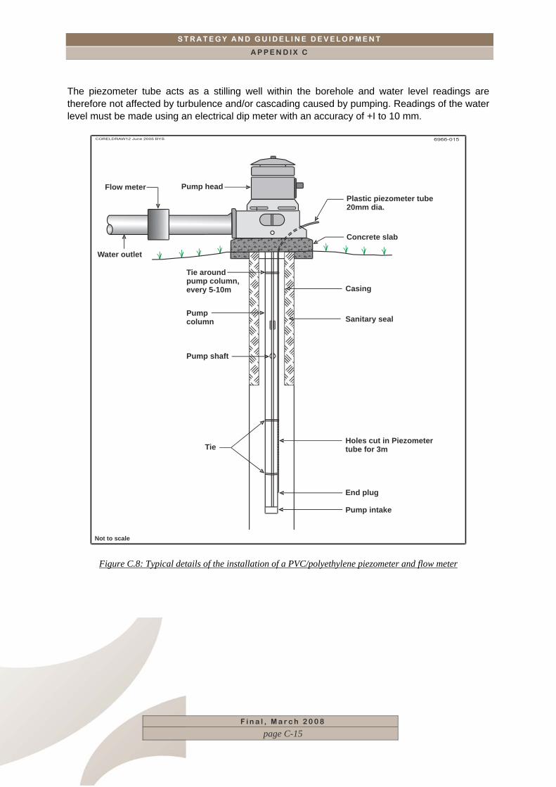
S T R A T E G Y A N D G U I D E L I N E D E V E L O P M E N T
A P P E N D I X C
The piezometer tube acts as a stilling well within the borehole and water level readings are therefore not affected by turbulence and/or cascading caused by pumping. Readings of the water level must be made using an electrical dip meter with an accuracy of +I to 10 mm.
Not to scale
Plastic piezometer tube 20mm dia.
Concrete slab
Casing
Sanitary seal
Holes cut in Piezometertube for 3mTie
Pump shaft
Pump column
Tie aroundpump column,every 5-10m
Water outlet
Pump headFlow meter
End plug
Pump intake
Figure C.8: Typical details of the installation of a PVC/polyethylene piezometer and flow meter
F i n a l , M a r c h 2 0 0 8
page C-15
S T R A T E G Y A N D G U I D E L I N E D E V E L O P M E N T
A P P E N D I X C
F i n a l , M a r c h 2 0 0 8
page C-16
C.3.5 Test Continuity Pumping tests must be carried out for the minimum duration as specified in Table C.2. In the event of a mechanical breakdown or other reason preventing the test from being completed, the test must be repeated after allowing recovery of the water level to its original level.
C.3.6 Further Information The reader is referred to the following documents should further details of testing techniques be required: Driscoll, Fletcher. G.,1986 Groundwater and Wells. Second Edition. Published by Johnson Filtration Systems Inc. St. Paul, Minnestoa 55112 ISBN 0-9616456-0-1
C.4 Water sampling and quality Knowledge of the groundwater chemistry and, where required, bacteriological quality, is essential to:
Determine the suitability of the groundwater for the intended use, and
For the overall groundwater resource management.
Measurement of temperature, electrical conductivity and pH should be taken during the constant discharge test, using field kits. These measurements should be taken at the beginning of the test, halfway through the test and a few minutes before the termination of the test. Other constituents can be measured using portable test kits as required. A water sample should be collected before the end of the pumping test. The sample should be submitted to a reputable (accredited) laboratory to undertake the required testwork. Each sample must be analyzed for pH, TDS, conductivity, Ca, Mg, Na, K, HCO3/CO2, SO4, Cl, NO3, Fe, F, and Mn. Where groundwater pollution is suspected, it will be necessary to also analyse samples for specific constituents associated with the suspected pollution. Details of the correct water sampling procedures are given in Water Research Commission Sampling Manual (second edition) by Weaver and Cave 2007.
S T R A T E G Y A N D G U I D E L I N E D E V E L O P M E N T
A P P E N D I X C
F i n a l , M a r c h 2 0 0 8
page C-17
C.5 Rehabilitation of boreholes Rehabilitation is necessary when the yield performance of a borehole decreases with time. It is carried out to increase the yield and/or to stabilise the borehole. Decrease in the hydraulic performance and efficiency of borehole can be caused by:
Chemical encrustation and/or build up slime due to iron bacteria of the slotted casing section and/or of the water bearing formation thereby reducing permeability,
The formation and, where installed, the slotted casing, become clogged by fine particles,
Pumping of wad and silt due to collapse of the sidewalls and/or corrosion of the casing, leading to ingress of overburden or collapsing zones.
Rehabilitation of boreholes is achieved by one or more of the following techniques:
Chemical rehabilitation including acidification and oxygenation
Mechanical rehabilitation (cleaning using surging, airlifting, hydrofracturing, etc)
Replacement of the casings/screens installed in the borehole
Inserting a smaller diameter casing inside the original casing after the borehole has been cleaned out.
The mechanical and chemical rehabilitation techniques are essentially those used for borehole development.


S T R A T E G Y A N D G U I D E L I N E D E V E L O P M E N T
A P P E N D I X D 1
F i n a l , M a r c h 2 0 0 8
page i
CCOONNTTEENNTTSS
APPENDIX D1. GENERIC TABLE OF CONTENTS ___________________ 1
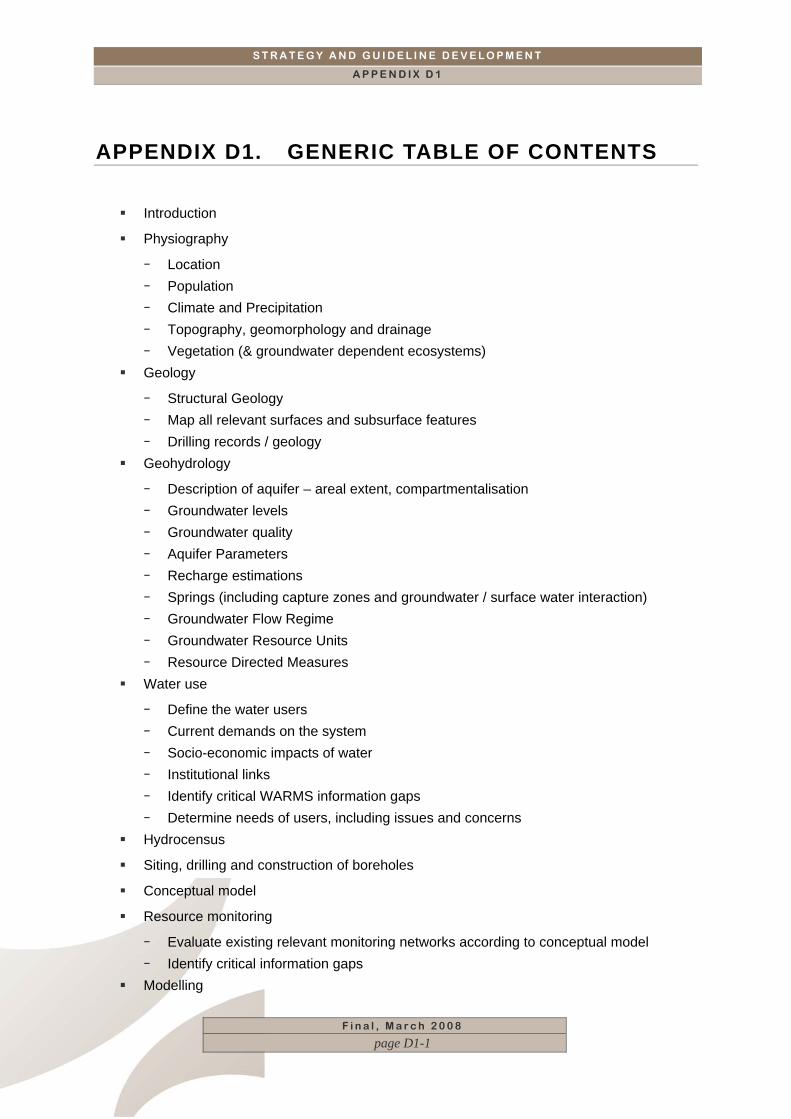
S T R A T E G Y A N D G U I D E L I N E D E V E L O P M E N T
A P P E N D I X D 1
F i n a l , M a r c h 2 0 0 8
page D1-1
APPENDIX D1. GENERIC TABLE OF CONTENTS
Introduction
Physiography
− Location − Population − Climate and Precipitation − Topography, geomorphology and drainage − Vegetation (& groundwater dependent ecosystems)
Geology
− Structural Geology − Map all relevant surfaces and subsurface features − Drilling records / geology
Geohydrology
− Description of aquifer – areal extent, compartmentalisation − Groundwater levels − Groundwater quality − Aquifer Parameters − Recharge estimations − Springs (including capture zones and groundwater / surface water interaction) − Groundwater Flow Regime − Groundwater Resource Units − Resource Directed Measures
Water use
− Define the water users − Current demands on the system − Socio-economic impacts of water − Institutional links − Identify critical WARMS information gaps − Determine needs of users, including issues and concerns
Hydrocensus
Siting, drilling and construction of boreholes
Conceptual model
Resource monitoring
− Evaluate existing relevant monitoring networks according to conceptual model − Identify critical information gaps
Modelling

S T R A T E G Y A N D G U I D E L I N E D E V E L O P M E N T
A P P E N D I X D 1
F i n a l , M a r c h 2 0 0 8
page D1-2
− This can be various types of models e.g. analytical, numerical, risk-based Assessment and Conclusions
− Compare water availability & requirements − Water quantity and quality issues − Risk assessment − Vulnerability assessment − Impacts − Groundwater protection zones


S T R A T E G Y A N D G U I D E L I N E D E V E L O P M E N T
A P P E N D I X D 2
F i n a l , M a r c h 2 0 0 8
page i
CCOONNTTEENNTTSS
APPENDIX D2. MODEL PLANNING REPORT _______________________ 1
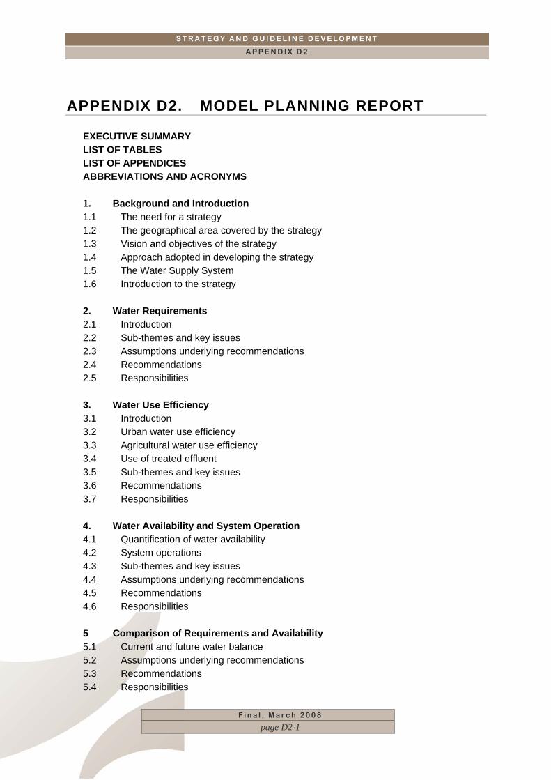
S T R A T E G Y A N D G U I D E L I N E D E V E L O P M E N T
A P P E N D I X D 2
F i n a l , M a r c h 2 0 0 8
page D2-1
APPENDIX D2. MODEL PLANNING REPORT
EXECUTIVE SUMMARY LIST OF TABLES LIST OF APPENDICES ABBREVIATIONS AND ACRONYMS 1. Background and Introduction 1.1 The need for a strategy 1.2 The geographical area covered by the strategy 1.3 Vision and objectives of the strategy 1.4 Approach adopted in developing the strategy 1.5 The Water Supply System 1.6 Introduction to the strategy 2. Water Requirements 2.1 Introduction 2.2 Sub-themes and key issues 2.3 Assumptions underlying recommendations 2.4 Recommendations 2.5 Responsibilities 3. Water Use Efficiency 3.1 Introduction 3.2 Urban water use efficiency 3.3 Agricultural water use efficiency 3.4 Use of treated effluent 3.5 Sub-themes and key issues 3.6 Recommendations 3.7 Responsibilities 4. Water Availability and System Operation 4.1 Quantification of water availability 4.2 System operations 4.3 Sub-themes and key issues 4.4 Assumptions underlying recommendations 4.5 Recommendations 4.6 Responsibilities 5 Comparison of Requirements and Availability 5.1 Current and future water balance 5.2 Assumptions underlying recommendations 5.3 Recommendations 5.4 Responsibilities

S T R A T E G Y A N D G U I D E L I N E D E V E L O P M E N T
A P P E N D I X D 2
F i n a l , M a r c h 2 0 0 8
page D2-2
6 Selection of Interventions and Decision Making Process 6.1 Introduction 6.2 Decision making process for selection 6.3 A short-list of interventions for further study 6.4 Sub-themes and key issues 6.5 Recommendations 6.6 Responsibilities 7 Risk 7.1 Introduction 7.2 Sub-themes and key issues 7.3 Assumptions underlying recommendations 7.4 Recommendations 7.5 Responsibilities 8 Water Resource Protection and Management 8.1 Introduction 8.2 Options for future use 8.3 Sub-themes and key issues 8.4 Recommendations 8.5 Responsibilities 9 Stakeholder Engagement 9.1 Introduction 9.2 Sub-themes and key issues 9.3 Assumptions underlying recommendations 9.4 Recommendations 9.5 Responsibilities 10 Implementation and Performance Monitoring 10.1 Introduction 10.2 National Water Act and National Water Strategy 10.3 Regional and local frameworks of plan 10.4 Relevant water institutions 10.5 Other factors that might influence the strategy 10.6 Current potential performance monitoring structures 10.7 Targets and key performance areas 10.8 Sub-themes and key issues 10.9 Assumptions underlying recommendations 10.10 Recommendations 10.11 Responsibilities
S T R A T E G Y A N D G U I D E L I N E D E V E L O P M E N T
A P P E N D I X D 2
F i n a l , M a r c h 2 0 0 8
page D2-3
LIST OF STRATEGY TABLES
1.1 Strategy theme and objectives 2.1 WATER REQUIREMENTS: Summarised key issues, issues and
approach
3.1 Estimates of water wastage and inefficient use 3.2 Activities to achieve WC/WDM goals 3.3 WATER USE EFFICIENCY: Summarised key issues, issues and
approach
4.1 Main schemes of the WCWSS 4.2 WATER AVAILABILITY AND SYSTEM OPERATION: Summarised
key issues, issues and approach
5.1 COMPARISON OF REQUIREMENTS AND AVAILABILITY: Summarised key issues, issues and approach
6.1 SELECTION OF INTERVENTIONS AND DECISION-MAKING: Summarised key issues, issues and approach
6.2 Required actions to support the information needs for the selection of interventions
7.1 RISK: Summarised key issues, issues and approach 8.1 WATER RESOURCES PROTECTION AND MANAGEMENT:
Summarised key issues, issues and approach
9.1 STAKEHOLDER ENGAGEMENT: Summarised key issues, issues and approach
10.1 IMPLEMENTATION AND PERFORMANCE MONITORING: Summarised key issues, issues and approach
LIST OF FIGURES
1.1 Geographical area covered by the strategy 1.2 WCWSS Reconciliation Strategy deliverables 2.1 Historical water use 2.2 estimated future and agricultural water requirements 4.1 The Water Supply System 5.1 Water balance for the Water Supply System 6.1 Potential interventions


S T R A T E G Y A N D G U I D E L I N E D E V E L O P M E N T
A P P E N D I X D 3
F i n a l , M a r c h 2 0 0 8
page i
CCOONNTTEENNTTSS
APPENDIX D3. GENERIC TABLE OF CONTENTS FOR THE INTEGRATED WATER RESOURCES MANAGEMENT PLAN (IWRMP) _________________________________ 1

S T R A T E G Y A N D G U I D E L I N E D E V E L O P M E N T
A P P E N D I X D 3
F i n a l , M a r c h 2 0 0 8
page D3-1
APPENDIX D3. GENERIC TABLE OF CONTENTS FOR THE INTEGRATED WATER RESOURCES MANAGEMENT PLAN (IWRMP)
Summary of existing information
− Problems, Issues & Concerns − Progress in IWRM
Resource Management Units
− Define the resource management units according to the technical and socio-economic information supplied
− Describe the monitoring networks according to the RMUs, including shortcomings − Extend groundwater monitoring networks if needed − Integrate monitoring networks – link this to a monitoring plan
Management goals
− Prioritise management goals − Recommendations
Define Management Instrument
Analyse various Options / Solutions
− Options need to be ranked by the technical expertise before presenting it to the stakeholders.
− At national level this will typically be WMA scale or cross-boundary type of issues. − At catchment level looking at which options to develop to address a specific need. − At site-specific level mostly 2 or 3 options which needs detail level study and
optimising designs.
STRATEGY TABLES
− Strategy tables are useful tools to enable implementing the strategies. The ISPs can be used as an example of the strategies that take priority in a WMA and further work can be built on this
− Management/Development Plan according to the outcome of the strategy phase, IWRM in the area
− A description of the approach that will be followed in managing the area Purpose of the plan
Water resource situation
− A very brief description of the most relevant information in the area summarised from the situation analysis and strategy

S T R A T E G Y A N D G U I D E L I N E D E V E L O P M E N T
A P P E N D I X D 3
F i n a l , M a r c h 2 0 0 8
page D3-2
− Set RQOs according to this information Management action plan
− From the actions that were defined in the strategy the following should be developed for implementation.
− Management Activities − Management Responsibilities − Management Timeframes & Budget − Progress Indicators
Conclusions
MANAGEMENT TABLES
− Populate management tables according to strategy tables, summarising the activities, responsibilities, time frames and budget.
Summary
It is helpful to summarise the management tables according to the various stakeholders, then one can see upfront what your next task will be in this overall framework.


S T R A T E G Y A N D G U I D E L I N E D E V E L O P M E N T
A P P E N D I X D 4
F i n a l , M a r c h 2 0 0 8
page i
CCOONNTTEENNTTSS
APPENDIX D4. GENERIC TABLE OF CONTENTS FOR HYDROGEOLOGIST INPUT INTO ENVIRONMENTAL IMPACT ASSESSMENT (EIA) PROCESSES ____________________________ 1

S T R A T E G Y A N D G U I D E L I N E D E V E L O P M E N T
A P P E N D I X D 4
F i n a l , M a r c h 2 0 0 8
page D4-1
APPENDIX D4. GENERIC TABLE OF CONTENTS FOR HYDROGEOLOGIST INPUT INTO ENVIRONMENTAL IMPACT ASSESSMENT (EIA) PROCESSES
Adopted from: Saayman, I. 2005. Guideline for involving hydrogeologists in EIA processes: Edition 1. CSIR Report No ENV-S-C 2005 053 D. Republic of South Africa, Provincial Government of the Western Cape, Department of Environmental Affairs & Development Planning, Cape Town.
Background information
- Relevant project and site related information - Information describing the affected environment - The legal, policy and planning context - Information generated by other specialists in the EIA process
Specialist input for impact assessment and recommending management actions
- Predicting potential impacts - Interpreting impact assessment criteria - Establishing thresholds of significance - Describing the distribution of impacts – beneficiaries and losers - Identifying key uncertainties, assumptions and risks - Defining confidence levels and constraints to input - Recommending Management actions - Identifying the best practicable environmental option - Communicating the findings of the specialist input
Specialist input to the monitoring programmme