Embed Size (px)
Citation preview
1. General Information
1.1. Equipment
TECHNICALIMAINTENANCE
HANDBOOK
2. Construction and Layout
2.1. Racks
2.2. Dimmer Modules
STM 10120 WAY INSTALLATIONS
L 3. Installation and Connections
3.1. Installation
3.2. Ventilation
3.3. Mounting
3.4. Connections
4. Rack Maintenance
4.1. Rack Circuit Details
4.2. Check and Test Procedure
4.3. Dismantling/Replacement Information
4.4. Routine Maintenance
4.5. Fans
4.6. Fault Diagnosis
L Appendix 'A1 STM Open Loop Modules Maintenance
A.1. Module Sizes
A.2. Circuit Description
A.3. Dismantling/Replacernent Information
A.4. Check and Test Procedures
A.5. Fault Diagnosis
Supplements
1105 - Series 'St Law Trigger Cards or
1114 - Series Square Law Trigger Cards List of Regional Offices and Associate Companies
Page
7708 Issue 2

L. d r
S Th
rar
to
stc
R a c
E a c
f UE
',L
* : With laminated-core filter unit.
** : With C-core filter unit.
MODULE TYPE
I s s u e 2 7708
CIRCUIT
RATING
KW
RATING
2/2RKW
5KW
1 0 A
2 0 A
* STM 20
** STM 25C
STM 50C
STM/T/M
2 . CONSTRUCTION AND LAYOUT
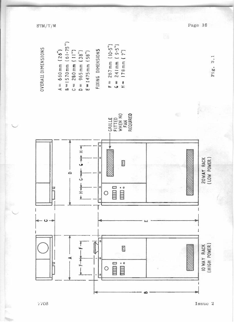
2 . 1 Racks ( s e e F i g , 2 . 1 Page No. 1 6 ) .
The r a c k s are o f t o t a l l y e n c l o s e d c o n s t r u c t i o n , d e s i g n e d
f o r i n s t a l l a t i o n a s f r e e s t a n d i n g u n i t s . An i n t e g r a l
b r a c k e t w i t h h o l e s is p r o v i d e d a t t h e t o p o f e a c h rack
t o f a c i l i t a t e s e c u r i n g t o a w a l l o r v e r t i c a l s u r f a c e ;
a l t e r n a t i v e l y two s i m i l a r r a c k s may be mounted back- to-
back and s e c u r e d t o e a c h o t h e r . The f u s e - p a n e l is
h i n g e d t o p r o v i d e a c c e s s t o t h e t e r m i n a l compartment .
The D i m m e r Modules are mounted i n t h e r e m a i n i n g pa r t o f
t h e r a c k i n columns ( o f 3 and 7 i n STM-10 r a c k s ) , and
m e t a l p a n e l s s e c u r e d by s c r e w s p r o v i d e a c c e s s f o r
m a i n t e n a n c e purposes .
Note: Some module p o s i t i o n s may c o n t a i n "Non-dim"
B lank P a n e l s ,
Rack (S) c o n t a i n i n g t h e f o l l o w i n g module c o m b i n a t i o n s
a r e f i t t e d w i t h a f a n t o a s s i s t i n t e r n a l v e n t i l a t i o n ;
1 ) More t h a n 50% STM 25C modules .
2 ) More t h a n 3 STM 5 0 C modules i n a r a c k , ( 2 i n a 10 way
r a c k ) when t h e rack is o t h e r w i s e f u l l of STM 20 m
modules . I n t h i s case, t h e r e must n o t b e more t h a n
1 STM 50C module p e r column.
A i r e n t r y is v i a a g r i l l e a t t h e b o t t o m o f t h e r a c k
f r o n t p a n e l .
2 . 2 D i m m e r Modules
The R e f . Number f o r t h e module Is shown on a l a b e l
a f f i x e d t o t h e b a s e - p l a t e . L e t t e r - s u f f i x C t o t h e
Ref . Number i n d i c a t e s t h a t t h e f i - l t e r u n i t is o f C-core
d e s i g n .
On modu le s w i t h Plug- i .n T r i g g e r c a r d s , t h e p l u g - i n
c o n n e c t o r i s mounted on t o p of t h e h e a t - s i n k s .
7708 I s s u e 2
Note: Each rack or group of racks is supplied with a R e f .
855 Suppressor Unit consisting of four capacitors.
Mount this unit close to the incoming mains-supply
busbars; see Fig. 2.2 (Page No. 17) for dimensions
and paragraph 3.4.2a for connections.
3.1 Installation ---
To minimise expensive cable-runs to the lamp loads,
site the racks as near to the loads as practicable.
T h e r e possible, group two or more racks together at
one location. Avoid any accoustically 'livet
position in the acting or audience area, since the
racks are not completely silent in operation.
An adequately fused isolator for the incoming mains-
supply must be provided, preferably one near to each
rack. The spare label reading 'High Voltage
Insulation Testers Not To Be Used On This Equipment',
provided with the rack(s), should be fixed to the main
isolator switch. In choosing the location for
individual or grouped racks, ensure that free flow of
air through each rack (air-inlet at bottom and outlet
at top) is not impeded in any way. Also allow enough
clearance to the left of the rack to allow the fuse
panel to be hinged open more than 90° and permit free
access to the terminals.
3.2 Ventilation
The forced ventilation or natural convection in each
rack is adequate to disperse the heat dissipated in
the rack (less than 23% of maximum load or supply KW
rating, whichever is the smaller), so long as the
inlet air temperature does not exceed 3 5 O ~ (95'~).
Air conditioning equipment may be necessary in some
locations to naintain the ambient temperature below
Issue 2 7705
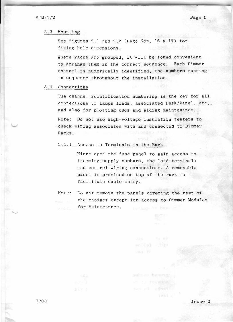
3.3 M o u n t i n g
S e e f i g u r e s 2 . 1 a n d 2 . 2 ( P a g e
f i x i n g - h o l e d i m e n s i o n s .
Where r a c k s are g r o u p e d , i t W
t o a r r a n g e them i n the c o r r e c
c h a n n e l is n u m e r i c a l l y i d e n t i
i n s e q u e n c e t h r o u g h o u t t h e i n
3 . 4 C o n n e c t i o n s
The c h a n n e l i d e n t i f i c a t i o n nu
c o n n e c t i o n s t o l a m p s loads , a
a n d also fo r p l o t t i n g c u e s a n
Note: Do n o t u s e h i g h - v o l t a g
c h e c k w i r i n g a s s o c i a t e d w i t h
R a c k s ,
3 . 4 . 1 Access t o T e r m i n a l s i n
H i n g e o p e n t h e f u s e p a n e l t o g a i n access t o
i n c o m i n g - s u p p l y b u s b a r s , t h e l o a d t e r m i n a l s
a n d c o n t r o l - w i r i n g c o n n e c t i o n s . A r e m o v a b l e
p a n e l is p r o v i d e d o n t o p of t h e r a c k t o
f a c i l i t a t e c a b l e - e n t r y .
N o t e : Do n o t remove t h e p a n e l s c o v e r i n g t h e rest of
t h e c a b i n e t e x c e p t f o r access t o Dimmer Module
f o r M a i n t e n a n c e .
7708 I s s u e 2
Page 6
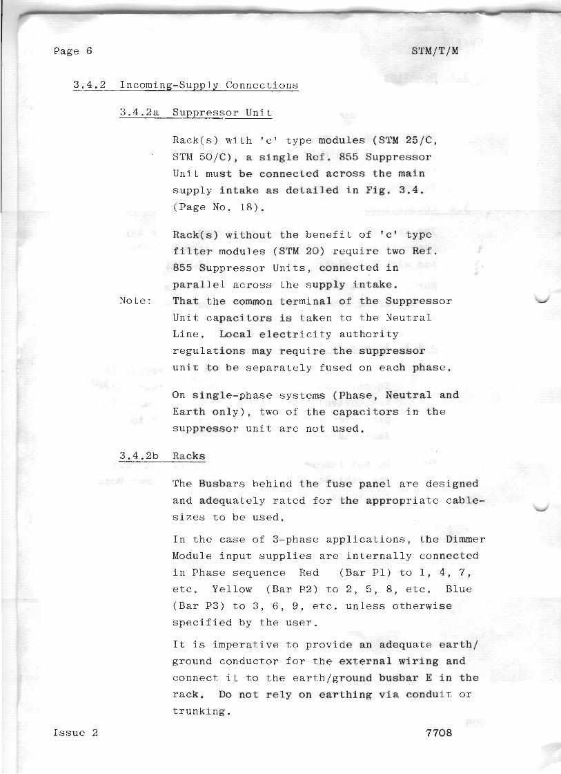
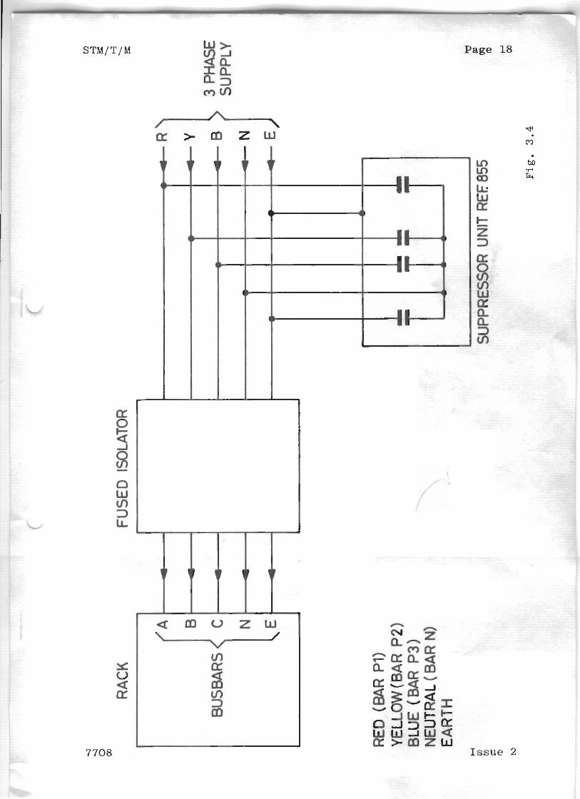
3 . 4 . 2 Incoming-Supply C o n n e c t i o n s
3 . 4 . 2 a S u p p r e s s o r U n i t
R a c k ( s ) w i t h ' c ' t y p e modu le s (STM 25/C,
STM 5 0 / C ) , a s i n g l e R e f . 855 S u p p r e s s o r
U n i t mus t be c o n n e c t e d a c r o s s t h e main
s u p p l y i n t a k e as d e t a i l e d i n F i g . 3.4 .
( P a g e No. 1 8 ) .
R a c k ( s ) w i t h o u t t h e b e n e f i t o f ' c ' t y p e
f i l t e r modu le s (STM 20) r e q u i r e two R e f .
855 S u p p r e s s o r U n i t s , c o n n e c t e d i n
p a r a l l e l across t h e s u p p l y i n t a k e .
No te : T h a t t h e common t e r m i n a l o f t h e S u p p r e s s o r
U n i t c a p a c i t o r s is t a k e n t o t h e N e u t r a l
L i n e . Local e l e c t r i c i t y a u t h o r i t y
r e g u l a t i o n s may r e q u i r e t h e s u p p r e s s o r
u n i t t o b e s e p a r a t e l y f u s e d on e a c h p h a s e .
On s i n g l e - p h a s e s y s t e m s ( P h a s e , N e u t r a l and
E a r t h o n l y ) , t w o o f t h e c a p a c i t o r s i n t h e
s u p p r e s s o r u n i t are n o t u s e d .
3 .4 .2b Racks
The B u s b a r s b e h i n d t h e f u s e p a n e l a r e d e s i g n e d
and a d e q u a t e l y r a t e d f o r t h e a p p r o p r i a t e c a b l e - 4
s i z e s t o b e u s e d .
I n t h e case o f 3 -phase a p p l i c a t i o n s , t h e D i m m e r
Module i n p u t s u p p l i e s are i n t e r n a l l y c o n n e c t e d
i n P h a s e s e q u e n c e R e d ( B a r P1 ) t o 1, 4 , 7 ,
etc. Y e l l o w ( B a r P2 ) t o 2 , 5 , 8 , e t c . B l u e
( B a r P3) t o 3 , 6 , 9 , e t c . u n l e s s o t h e r w i s e
s p e c i f i e d by t h e u s e r .
I t is i m p e r a t i v e t o p r o v i d e a n a d e q u a t e e a r t h /
g r o u n d c o n d u c t o r f o r t h e ex te rna l w i r i n g and
c o n n e c t i t t o t h e e a r t h / g r o u n d b u s b a r E i n t h e
r a c k . Do n o t r e l y on e a r t h i n g v i a c o n d u i t or
t r u n k i n g .
I s s u e 2 7 708
STM/T/M Page 7
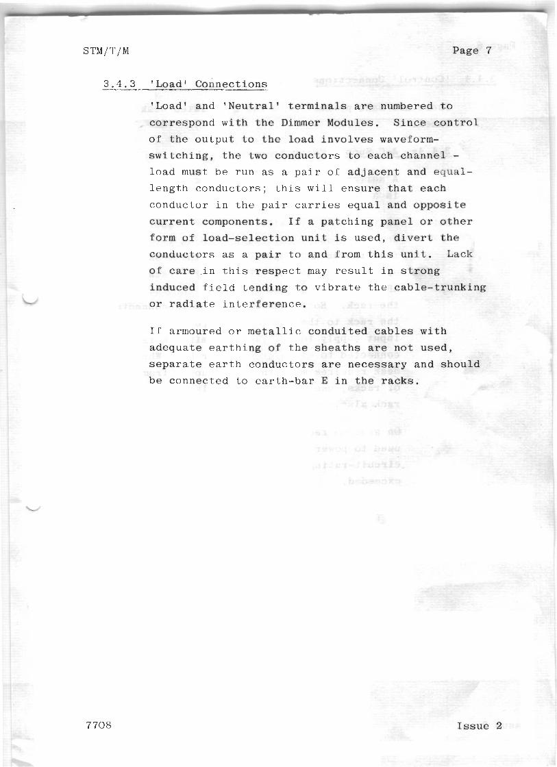
3 . 4 . 3 ' L o a d 1 C o n n e c t i o n s
!Load1 and ' N e u t r a l 1 t e r m i n a l s a r e numbered t o
c o r r e s p o n d w i t h t h e D i m m e r Modules . S i n c e c o n t r o l
o f t h e o u t p u t t o t h e l o a d i n v o l v e s waveform-
s w i t c h i n g , t h e two c o n d u c t o r s t o e a c h c h a n n e l - l o a d must b e r u n as a p a i r o f a d j a c e n t and e q u a l -
l e n g t h c o n d u c t o r s ; t h i s w i l l e n s u r e t h a t e a c h
c o n d u c t o r i n t h e p a i r carr ies e q u a l and o p p o s i t e
c u r r e n t components . I f a p a t c h i n g p a n e l o r o t h e r
form of l o a d - s e l e c t i o n u n i t is u s e d , d i v e r t t h e
c o n d u c t o r s as a pair t o and from t h i s u n i t . Lack
o f care i n t h i s r e s p e c t may r e s u l t i n s t r o n g
i n d u c e d f i e l d t e n d i n g t o v i b r a t e t h e c a b l e - t r u n k i n g
o r r a d i a t e i n t e r f e r e n c e .
I f a rmoured o r m e t a l l i c c o n d u i t e d cables w i t h
a d e q u a t e e a r t h i n g of t h e s h e a t h s are n o t u s e d ,
s e p a r a t e e a r t h c o n d u c t o r s are n e c e s s a r y a n d s h o u l d
be c o n n e c t e d t o e a r t h - b a r E i n t h e r a c k s .
7708 I s s u e 2
Issue 2 7702
STM/T/M P a g e 9
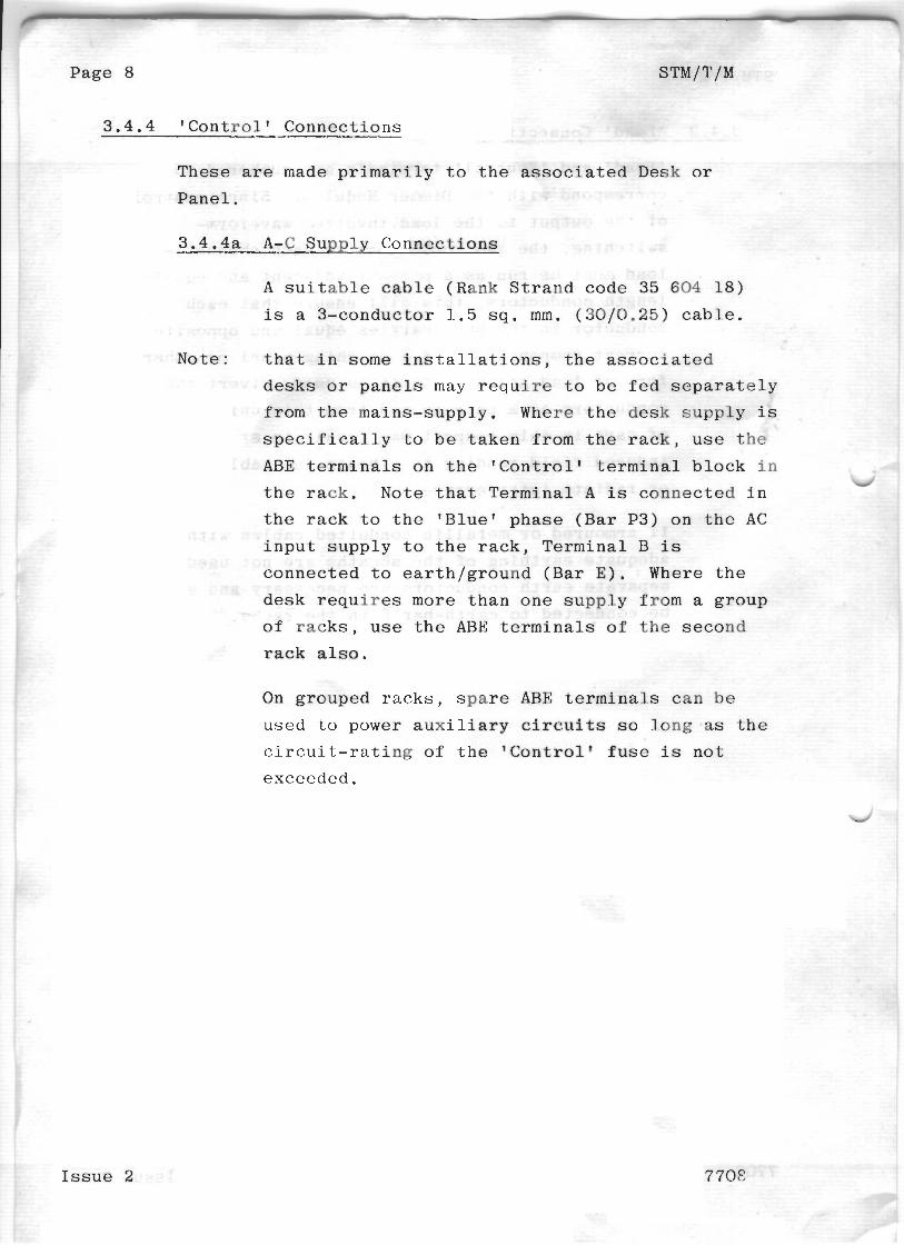
3 . 3 . 4 b C o n t r o l - S i g n a l C o n n e c t i o n s
U s e t e r m i n a l s 1 t o 10 ( o r 2 0 ) and '01 v
t e r m i n a l b l o c k . S i n c e t h e w i r i n g nas t o c a r r y l ess
t h a n 24V a t a few mA, any s u i t a b l e m u l t i - c o n d u c t o r
cable c a n b e u s e d s u b j e c t t o l o c a l a u t h o r i t y
r e g u l a t i o n s . A s u i t a b l e c a b l e (Rank S t r a n d E l e c t r i c
c o d e 35 6 0 1 1 1 ) is a 1 2 - c o n d u c t o r o r 0.5 s q . mm.,
( 1 6 / 0 . 2 ) PVC- insu l a t ed a n d s h e a t h e d c a b l e , t o b e u s e d
o n e cable per e a c h 10 c h a n n e l s . T h i s cable h a s t h e
a d v a n t a g e of 250V-grade i n s u l a t i o n a n d d o e s n o t h a v e
t o b e s e g r e g a t e d f rom m a i n s - v o l t a g e c o n d u c t o r s .
Connec t e a c h numbered t e r m i n a l t o t h e a p p r - u p r - i a t e
numbered t e r m i n a l ( f r o m t h e c h a n n e l l e v e r p o t e n t i o -
meter c i r c u i t s ) o n the a s s o c i a t e d Desk o r P a n e l ;
c o n n e c t t h e common r e t u r n l i n e t o T e r m i n a l C.
U s i n g t h e a b o v e 1 2 - c o n d u c t o r c a b l e , a c o n s i s t e n t
s e q u e n c e o f c o n n e c t i n g c o n d u c t o r s t o numbered
t e r m i n a l s ( e . g . w h f t e , s l a t e , b rown , r e d , r e d / b l u e ,
r e d l w h i t e , p i n k , orange, y e l l o w , b l u e , v i o l e t a n d
b l a c k ) w i l l f a c i l i t a t e c h a n n e l i d e n t i f i c a t i o n f o r
m a i n t e n a n c e p u r p o s e s a t a la ter d a t e .
3 . 4 . 5 O t h e r I n f o r m a t i o n
When a l l c o n n e c t i o n s h a v e b e e n made t o a r a c k ,
remove all c a b l e - e n d s and o t h e r d e b r i s f r o m t h e
t e r m i n a l c o m p a r t m e n t ; c h e c k a l l c o n n e c t i o n s care-
f u l l y , e s p e c i a l l y t o e n s u r e t h a t i n s u l a t i o n is
n o t t r a p p e d i n t h e p r e s s u r e - p a d t e r m i n a l s ; close
t h e f u s e p a n e l s .
7708 I s s u e 2
3 . 4 . 5 a Lamp-Loads
The D i m m e r s a r e d e s i g n e d t o c o n t r o l t u n g s t e n - l o a d
of the same v o l t a g e r a t i n g a s t h e ma ins - supp ly .
E a c h channel-dimmer r e q u i r e s a minimum l o a d o f 150W
f o r s a t i s f a c t o r y o p e r a t i o n ; h e n c e s m a l l e r t e s t - l a m p s
o r neon i n d i c a t o r s s h o u l d n o t b e u s e d as e n t i r e l o a d s .
The D i m m e r s w i l l a l s o c o n t r o l t r a n s f o r m e r - f e d l o a d s
p r o v i d e d t h e l o a d on t h e D i m m e r is i n e x c e s s of 300
w a t t s , e i t h e r d u e t o t r a n s f o r m e r s s e c o n d a r y loads o r
some o t h e r b a l l a s t . T r a n s f o r m e r s must b e i n d i v i d u a l l y
f u s e d , and s i t u a t i o n s s u c h a s o n e t r a n s f o r m e r f e e d i n g
o n e t u n g s t e n lamp l o a d w i t h no o t h e r b a l l a s t a v o i d e d ,
s i n c e i f t h i s lamp f a i l e d , t h e D i m m e r would be 4
s u b j e c t e d t o an u n l o a d e d t r a n s f o r m e r l o a d (i.e. a l o a d
u n d e r 300 w a t t s ) . Al lowance m u s t be made f o r t h e
t r a n s f o r m e r m a g n e t i z i n g c u r r e n t when c a l c u l a t i n g t h e
l o a d c u r r e n t . The maximum c ~ n t i n u o u s c u r r e n t r a t i n g
o f the D i m m e r s for t h i s purpose is 10 amps (2/24KW) o r
20 amps ( 5KW 1.
3 . 4 . 5 b Load-Line T e r m i n a t i o n s
T h e s e s h o u l d p r e f e r a b l y b e t o s o c k e t o u t l e t s ' numbered
t o c o r r e s p o n d w i t h t h e c h a n n e l i d e n t i f i c a t i o n numbers ,
and f o r t h e f l e x i b i l i t y u s u a l l y r e q u i r e d o f s t a g e and
s t u d i o l i g h t i n g , a s t a n d a r d s o c k e t . o u t l e t s h o u l d be 2
a d o p t e d where p o s s i b l e .
I n t h e U n i t e d Kingdom, 1 5 amp, 3 -p in BS546 o u t l e t s a r e
u s e d i n m o s t i n s t a l l a t i o n s . For h i g h - w a t t a g e loads
r e q u i r i n g o u t l e t s o f more t h a n 15A r a t i n g , s u i t a b l y
r a t e d r e c e p t a c l e s must b e u s e d , 32 amp c o n n e c t o r s t o
CEE. 1 7 a r e s u g g e s t e d .
F o r a p p l i c a t i o n s i n c o u n t r i e s o t h e r t h a n t h e UK, l o c a l
p r a c t i c e s o r r e g u l a t i o n s must p r e v a i l .
I s s u e 2 7708
STM/T/M P a g e 11
3 . 4 . 5 ~ A s s o c i a t e d Sound S y s t e m I n s t a l l a t i o n s
Waveform s w i t c h i n g , s u c h as p r o v i d e d b y t h y r i s t o r
D i m m e r s , c a n r e v e a l , i n t h e form o f s p u r i o u s
i n t e r f e r e n c e , p r e v i o u s l y u n s u s p e c t e d e a r t h - l o o p s i n
t h e a s s o c i a t e d s o u n d - s y s t e m i n s t a l l a t i o n s . C a r e f u l
i n s p e c t i o n o f s o u n d - s y s t e m e a r t h i n g , s c r e e n i n g , e tc .
may be n e c e s s a r y t o remedy a n y e a r t h l o o p s .
H i g h i m p e d a n c e m i c r o p h o n e l i n e s are a l so s u s c e p t i b l e
t o t h e p i c k - u p o f s w i t c h i n g ' n o i s e ' from lamp-
c i r c u i t s ; low i m p e d a n c e b a l a n c e d l i n e s s u c h as t h o s e
u s e d f o r m o v i n g - c o i l m i c r o p h o n e s are most s u i t a b l e ,
e s p e c i a l l y i f l o n g a u d i o c a b l e - r u n s are n e c e s s a r y .
3 . 4 . 5 d O t h e r C o n n e c t i o n s
D o n o t c o n n e c t o r o p e r a t e f l a s h b o x e s o r s im i l a r
p y r o t e c h n i c d e v i c e s ( o r a n y a p p l i a n c e l i a b l e t o
a b s o r b s u r g e s o f e x c e s s i v e power f r o m t h e m a i n s -
s u p p l y ) f r o m t h e D i m m e r o r a s s o c i a t e d l o a d c i r c u i t s .
O p e r a t e s u c h d e v i c e s s e p a r a t e l y f r o m t h e m a i n s -
s u p p l y , u n d e r loca l ( n o t r e m o t e ) c o n t r o l b y someone
n e a r t h e d e v i c e a n d w i t h a direct v i e w o f i t .
7708 I s s u e 2
Page 12 STM/T/M
4 . RACK MAINTENANCE
C i r c u i t d e s c r i p t i o n s and Ma in t enance i n f o r m a t i o n f o r t h e
modules and t r i g g e r c a r d s are c o n t a i n e d i n a s e p a r a t e
a p p e n d i x a c c o r d i n g t o t h e dimmers s u p p l i e d w i t h t h e r a c k s .
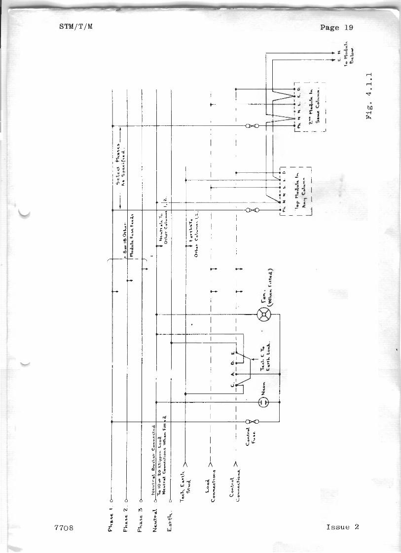
4 . 1 Rack C i r c u i t D e t a i l s
Racks c a n b e w i r e d f o r e i t h e r s t a r o p e r a t i o n ( F i g .
4 . 1 . 1 P a g e N o . 1 9 ) o r f o r Delta o p e r a t i o n ( F i g . 4 . 1 . 2
P a g e N o . 2 0 ) .
4 . 1 . 1 Star Connec t ed Rack
Any module i n a r a c k c a n b e wi red o n t o any p h a s e .
T h i s is s p e c i f i e d a t t h e t i m e of m a n u f a c t u r e . d'
The s u p p l y f o r e a c h module is t a k e n f rom t h e
a p p r o p r i a t e b u s b a r and s e n t v i a t h e module f u s e
t o t h e p h a s e c o n n e c t i o n o n t h e module . The
n e u t r a l s for t h e modules are l i n k e d t o g e t h e r i n
co lumns .
The load c o n n e c t i o n s t o t h e modules g o d i r e c t t o
t h e l o a d t e r m i n a l r a i l , as d o t h e c o n t r o l
c o n n e c t i o n s t o t h e modu le s . The t e c h n i c a l e a r t h
c o n n e c t i o n s f o r t h e modu le s are l i n k e d i n co lumns .
On some i n s t a l l a t i o n s , t h e t e c h n i c a l e a r t h / m a i n s
e a r t h l i n k f i t t e d on t h e c o n t r o l t e r m i n a l b l o c k , 4
may b e removed i f t h i s l i n k is made e l s e w h e r e i n
t h e s y s t e m .
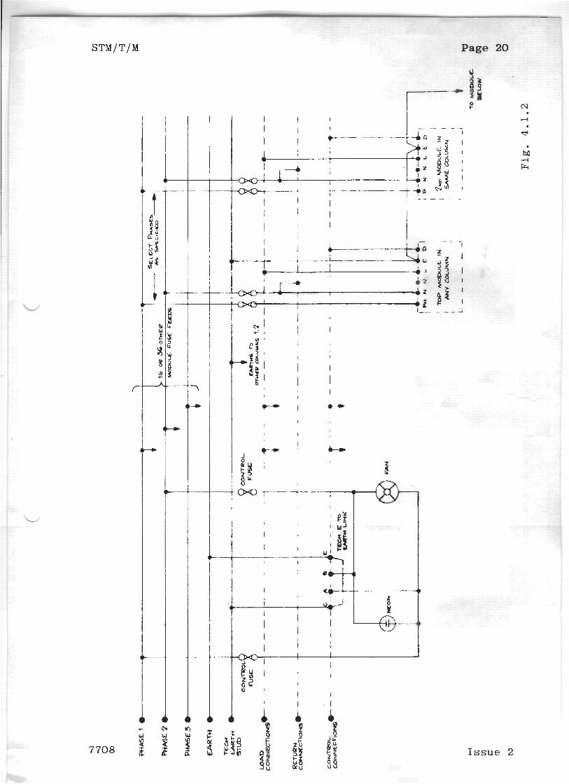
4 . 1 . 2 D e l t a Connec t ed Racks
T h e s e are s i m i l a r t o S t a r c o n n e c t e d r a c k s , e x c e p t
t h a t t h e " r e t u r n s " t o t h e modu le s a n d l o a d s are
i n d i v i d u a l l y f u s e d , and r o u t e d t o t h e modu le s
s e p a r a t e l y .
I s s u e 2 7708
STMII/T/M Page 13
4 . 2 Check a n d T e s t P r o c e d u r e
Check t h a t t h e a . c . s u p p l y t o t h e rack is s w i t c h e d o n :
note t h a t t h e n e o n o n t h e f u s e p a n e l i n d i c a t e s t h e
p r e s e n c e o f a n a . c . s u p p l y o n t h e control and f a n ( i f
f i t t e d ) s u p p l y . F a i l u r e o f t h e c o n t r o l f u s e w i l l
cause t h e n e o n t o e x t i n g u i s h . W i t h t h e f u s e p a n e l
h i n g e d o p e n , c h e c k t h a t t h e f u s e h o l d e r t e r m i n a l s are
' l i v e ' . I f a f a n is f i t t e d t o t h e r a c k e n s u r e that i t
is o p e r a t i n g c o r r e c t l y . A i r s h o u l d be blown OUT t h r o u g h
t h e t o p o f t h e r a c k .
4 . 3 D i s m a n t l i n g / R e p l a c e m e n t I n f o r m a t i o n
The e l e c t r i c a l c o n n e c t i o n s a r e made v i a a p r e s s u r e p a d
t e r m i n a l b l o c k . The f i v e w i r e s i n t o t h e module s h o u l d
b e d i s c o n n e c t e d b e f o r e a t t e m p t i n g t o remove t h e m o d u l e .
The m o d u l e is s e c u r e d t o t h e rack b y f o u r n u t s t h a t
screw o n t o s t u d s i n t h e r a c k t h a t pass t h r o u g h h o l e s
i n t h e m o d u l e b a s e p l a t e .
7708 I s s u e 2
R o u t i n e M a i n t e n a n c e
Note : Only a q u a l i f i e d e l e c t r i c i a n f a m i l i a r w i t h the
equ ipmen t s h o u l d u n d e r t a k e r e p l a c e m e n t o r o t h e r mainten-
a n c e work i n t h e r a c k s .
Always switch off t h e s u p p l y t o t h e rack b e f o r e unde r -
t a k i n g any m a i n t e n a n c e work . Remember that t h e t h y r i s t o r
h e a t s i n k s are a t m a i n s p o t e n t i a l a n d t a k e s u i t a b l e
p r e c a u t i o n s when t e s t i n g and m e a s u r i n g with the s u p p l y
s w i t c h e d o n .
The r a c k s r e q u i r e l i t t l e r o u t i n e maintenance a p a r t f rom
a t t e n t i o n t o t h e f a n i f f i t t e d . A p e r i o d i c a l i n s p e c t i o n 4
of t h e rack's a s s o c i a t e d w i r i n g a n d c o n n e c t i o n s i s
recommended a n d , i n v e r y d u s t prone e n v i r o n m e n t s , i n s p e c t
t h e rack i n t e r i o r f o r any a c c u m u l a t i o n of d u s t ; u s e a
s o f t b r u s h and a vacuum c l e a n e r t o remove a n y a c c u m u l a t e d
d u s t .
4 . 5 Fans
The f a n m a n u f a c t u r e r s a d v i s e that t h e f a n s u s e d h a v e
sealed l u b r i c a t i o n f o r t h e b e a r i n g s and t h i s is n o r m a l l y
a d e q u a t e f o r 10,000 h r s o p e r a t i n g t i m e . C o n t a c t t h e
Rank S t r a n d S e r v i c e d e p a r t m e n t a t t h e end o f t h i s p e r i o d
f o r b e a r i n g r e p l a c e m e n t . -
I s s u e 2 7708
4 . 6 F a u l t D i a g n o s i s
F a i l u r e o f a . c . s u p p l y t o a s s o c i a t e d Desk and
I n d i c a t o r neon ( a n d f a n i f f i t t e d ) : Check
' C o n t r o l t f u s e .
Complete f a i l u r e of power t o a module: Check
t h e module f u s e i n t h e f u s e p a n e l .
No o u t p u t from a dimmer module b u t power s u p p l i e d
t o module: Replace t h e dimmer module as a
comple te u n i t . S e t up t h e new module a s described
i n t h e a p p r o p r i a t e appendix o f t h e handbook.
7708 I s s u e 2
Issue 2
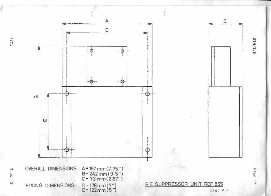
OVERALL DIMENSIONS A- 197 mm (7.75" ) 6- 24Zmm (9.5") C - 73 rnm(2-87")
FIXING DIE R.E SUPPRESSOF ? UNIT REF 855 F i g . 2 .2
Issue 2
Page 19
I s s u e 2
Page 20
I s s u e 2
STM/T/M Page 2 1
APPENDIX ' A ' STM OPEN LOOP MODULES MAINTZNANCE
A . l Module S i z e .P
STM 20 STM 25C STM 5 0 C
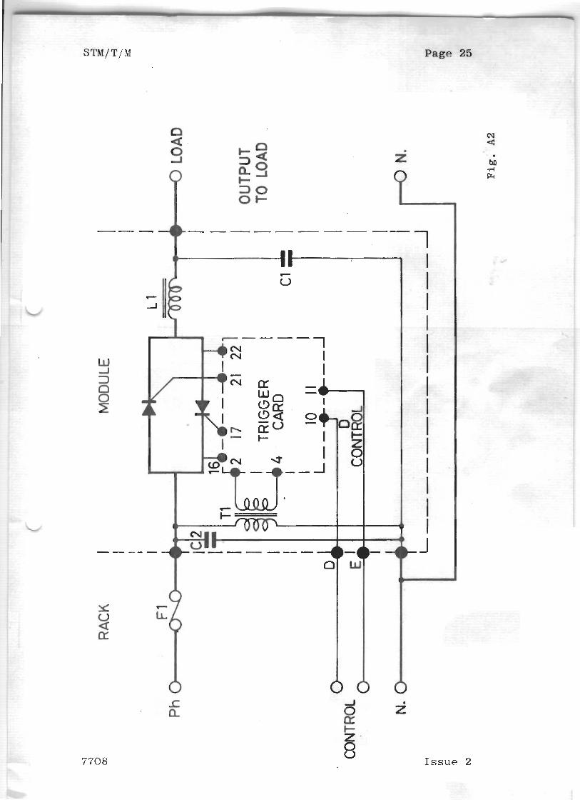
A.2 C i r c u i t D e s c r k ~ t i o n F i g . A . 2 (Page No. 25)
A . 2 . P P r i n c i p l e of O p e r a t i o n
An i n v e r s e - p a r a l l e l c o n n e c t e d p a i r o f t h y r i s t o r s
5CR1 a n d SCR2 a r e s u p p l i e d w i t h f i r i n g p u l s e s f r o m
t h e t r i g g e r c a r d s u c h t h a t each t h y r i s t o r is s w i t c h e d
o n a t t h e same r e l a t i v e i n s t a n t d u r i n g t h e a p p r o p r i a t e
h a l f c y c l e o f t h e m a i n s . The v a l u e of t h e control
s i g n a l i n t o t h e trigger card d e t e r m i n e s t h e f i r i n g
i n s t a n t , h e n c e d e t e r m i n i n g t h e RMS o u t p u t
p r e s e n t e d t o the load,
A . 2 . 2 C i r c u i t D e s c r i o t i o n
The c o n t r o l s i g n a l t o t h e dimmer i s a p p l i e
t e r m i n a l s D a n d E on t h e module t e r m i n a l b
c o n n e c t i o n s 3 a n d 5 o n t h e t r i g g e r c a r d .
c o n t r o l s i g n a l is n o r m a l l y d e r i v e d from a
v i a o n e d i o d e a n d a 1 0 k ohm r e s i s t o r . T h i
w i t h some o l d e r c o n t r o l s y s t e m s .
T e r m i n a l D is n e g a t i v e w i t h r e s p e c t t o E (
e a r t h ) . F u l l o u t p u t o f t h e dimmer o c c u r s
f u l l y n e g a t i v e .
F i r i n g p u l s e s t o t h e t h y r i s t s r gates a r e supplieu via
p a i r s o f c o n n e c t i o n s 1 1 / 1 2 a n d 1 4 / 1 6 o n t h e t r i g g e r
c a r d .
The i n d u c t o r L1 i s u s e d t o e x t e n d t h e c u r r e n t r isetime
o f t h e dimmer o u t p u t when t h e t h y r j s t o r s s w i t c h o n .
T h e i n d u c t o r c o m b i n e d w i t h c a p a c i t o r C 1 a n d t h e R e f .
855 s u p p r e s s o r u n i t ( f i t t e d external t o t h e dimmer rack)
s e r v e s t o r e d u c e a n y a u d i o and radio f r e q u e n c y
i n t e r f e r e n c e g e n e r a t e d b y t h e s w i t c h i n g o n of t h e
t h y r i s t o r s .
7708 I s s u e 2
l i n g / R e p l a c e m e n t I n f o r m a t i o r
Modules
The e l e c t r i c a l c o n n e c t i o n s t o a module are made v i a
p r e s s u r e p a d t e r m i n a l b l o c k m o u n t e d o n t h e m o d u l e .
The f i v e w i r e s i n t o t h e m o d u l e s h o u l d b e d i s c o n n e c t e d
b e f o r e a t t e m p t i n g t o remove t h e m o d u l e .
The m o d u l e is s e c u r e d t o t h e r a c k b y f o u r n u t s t h a t
screw o n t o s t u d s m o u n t e d i n t h e r a c k . T h e s e p a s s
t h r o u g h h o l e s i n t h e m o d u l e b a s e p l a t e .
T h y r i s t o r s
4
D o n o t a t t e m p t t o remove t h e h e a t s i n k s f r o m t h e m o d u l e
base p l a t e as t h e s e a re r i v e t e d i n p o s i t i o n a n d s e a l e d
f o r e l ec t r i ca l i s o l a t i o n o n t h e u n d e r s i d e o f t h e base-
p l a t e
U n s o l d e r t h e t h y r i s t o r g a t e c o n n e c t i o n a t t h e t r i g g e r
card, a n d d i s c o n n e c t t h e t h y r i s t o r c a t h o d e f r o m the
o p p o s i t e h e a t s i n k . Remove t h e t h y r i s t o r f r o m t h e h e a t -
s i n k .
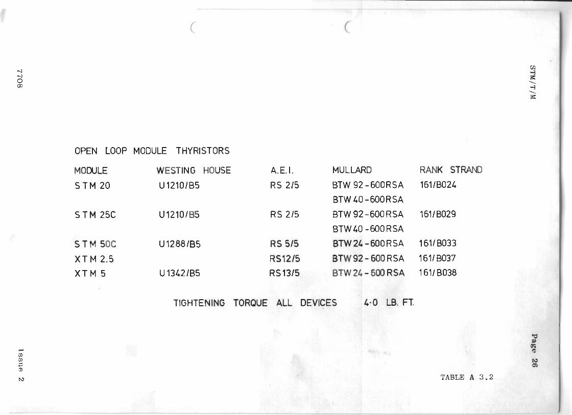
When r e p l a c i n g a t h y r i s t o r make s u r e t h a t t h e r e p l a c e m e n t
is t h e correct one f a r t h e m o d u l e .
Table A . 3 . 2 ( P a g e No. 26 ) g i v e s t h e correct t h y r i s t o r
t y p e s w i t h t h e i r s p e c i f i e d m o u n t i n g t o r q u e . Do n o t over --.'
t i g h t e n new t h y r i s t o r s o n t o t h e h e a t s i n k . I f p o s s i b l e
u s e a h e a t s i n k compound o r s i l i c o n e grease t o i n c r e a s e
t h e r m a l c o n d u c t i o n ,
A . 3 . 3 T r i g g e r Card
If t h e s e a r e w i r e d i n , t h e y are e i t h e r s e c u r e d t o t h e t o p
o f t h e h e a t s i n k s by f o u r n y l o n press f i t s t u d s , o r f o u r
i n s u l a t e d p i l l a r s d e p e n d i n g o n t h e t y p e of t r i g g e r c a r d .
I s s u e 2 7708
STM/T/M Page 2 3
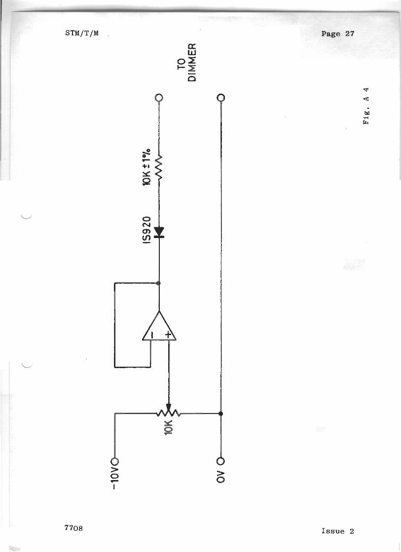
A.4 Check and T e s t P r o c e d u r e
Note: The t h y r i s t o r h e a t s i n k s o n t h e dimmer module are
a t ma ins p o t e n t i a l .
The module s h o u l d b e f e d w i t h a c o n t r o l s i g n a l
p r o v i d e d by t h e c i r c u i t i n F i g . A.4 ( P a g e N o . 27 )
and h a v e a l o a d o f 150W o r g r e a t e r .
A . 4 . 1 Check t h e o u t p u t o f T1, t h i s s h o u l d b e i n t h e r e g i o n
o f 12V a . c . , and c a n e a s i l y b e measu red o n c o n n e c t i o n s
7 and 9 o f t h e t r i g g e r c a r d .
A.4.2 Check t h a t a c o n t r o l s i g n a l is p r e s e n t e d t o t h e
t r i g g e r c a r d on c o n n e c t i o n s 3 and 5 when t h e f a d e r
l e v e r i s "up". And t h a t i t v a r i e s a s t h e f a d e r
l e v e l v a r i e s .
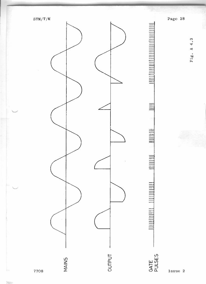
A . 4 . 3 Check t h a t t h e l o a d waveform a n d v o l t a g e o f t h e
dimmer v a r i e s a s t h e f a d e r l e v e l c h a n g e s . S e e F i g .
A .4 .3 ( P a g e No. 2 8 ) f o r t h e correct o u t p u t waveform.
A.4.4 Check t h a t a t r a i n o f p u l s e s , o f a p p r o x i m a t e l y 15v
a m p l i t u d e , is a p p l i e d t o the t h y r i s t o r g a t e s when
t h e f a d e r is on . The l e n g t h of the t r a i n s h o u l d
v a r y a s t h e f a d e r l e v e l var ies , S e e F i g . A.4.3
( P a g e N o . 2 8 ) .
7708 I s s u e 2
Page 24 , STM/T/M
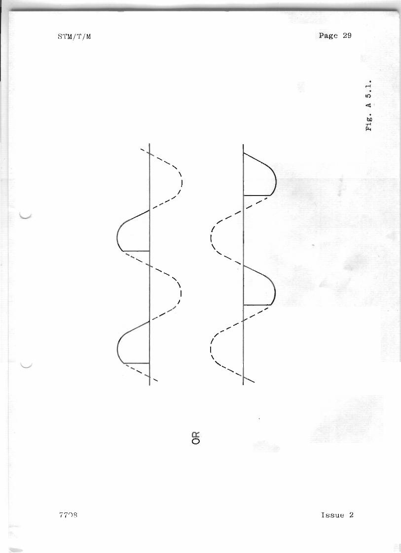
A . 5 F a u l t D i a g n o s i s
A . 5 . 1 F a i l u r e t o g e t F u l l O u t p u t f rom a Module
Check t h e o u t p u t waveform. I f i t is l i k e Fig. A . 5 . 1
( P a g e No. 2 9 ) t h e n check t h a t t h e gate p u l s e s t o t h e
a p p r o p r i a t e t h y r i s t o r are p r e s e n t . If t h e y a r e ,
change t h e t h y r i s t o r , i f n o t check t h e t r i g g e r c a r d .
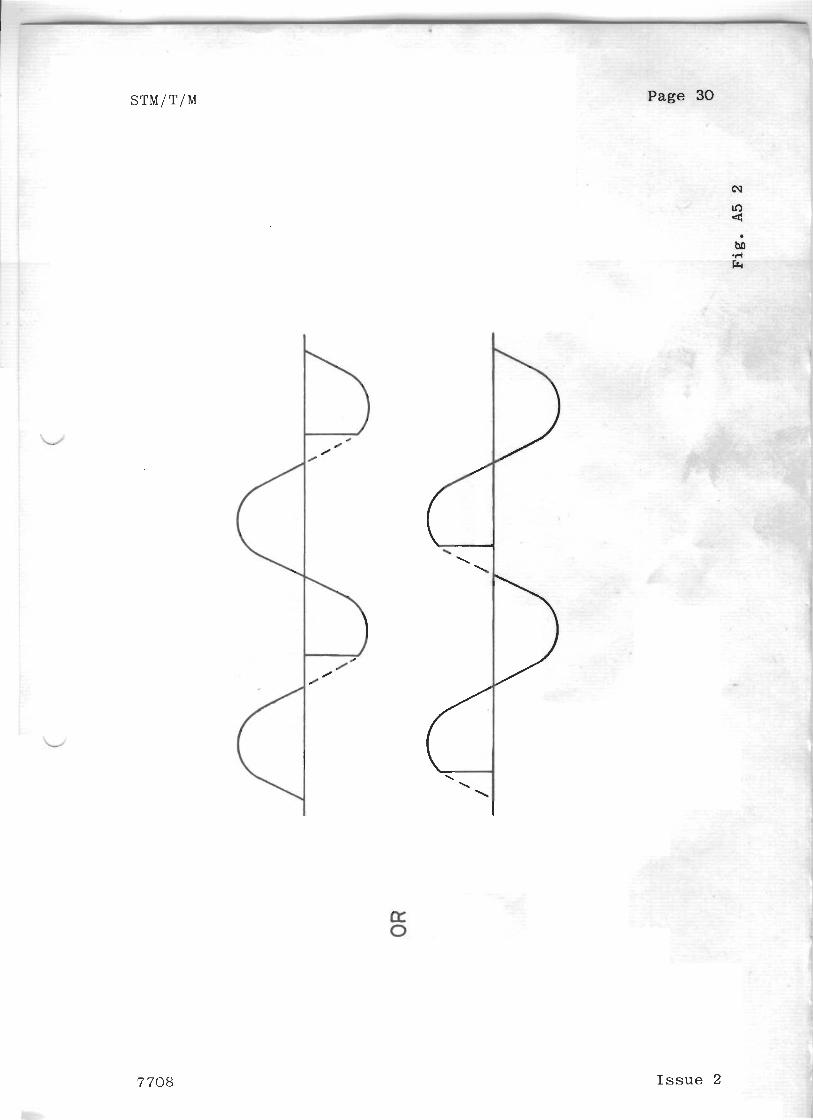
A . 5 . 2 F a i l u r e t o g e t Zero O u t p u t f rom a Module
Check t h e o u t p u t waveform. I f i t is l i k e F i g . A . 5 . 2
( P a g e N o . 30) t h e n check t h e g a t e p u l s e s . If t h e p u l s e s
are c o r r e c t change t h e t h y r i s t o r t h a t is c o n d u c t i n g a l l
t h e t i m e , if n o t , check t h e t r i g g e r c a r d . d
I s s u e 2 7708
I s s u e 2
OPEN LOOP MODULE THYRISTORS
MODULE WESTING HOUSE A.E.I. MULLARD RANK STRAND
STM 20 U12101B5 RS 215 BTW92-600RSA 16118024
BTW 40 -600RSA
STM 25C U12101B5 R S 215 BTW92-600RSA 16118029
BTW4O -600RSA
ST M SOC U1288165 RS 515 BTW 24 -600RSA 1611B033
XTM 2.5 R9215 BTW92-600RSA 16118037
XTM 5 U 13421B5 RS 1315 BTW 2L - 600 RSA 1611 B038
TIGHTENING TORQUE ALL DEVICES 4.0 LB. FT.
TABLE A 3
Page 27
Q'
Issue 2
Page. 28
Issue 2
Page 29
Issue 2
Issue 2
SUPPLEMENT
SECTION
'S' - LAW TRIGGER CARD
C . 1 . This circuit description covers the following
dimmer trigger-cards:-
Ref. 1105 Standard JTM/STM
Ref. 1101 Plug-in JTM/STM/PTM
Ref. 1181 XTM
The component numbers refer to Fig. C.2. at the
end of this section.
7708 Issue 1
Page 2
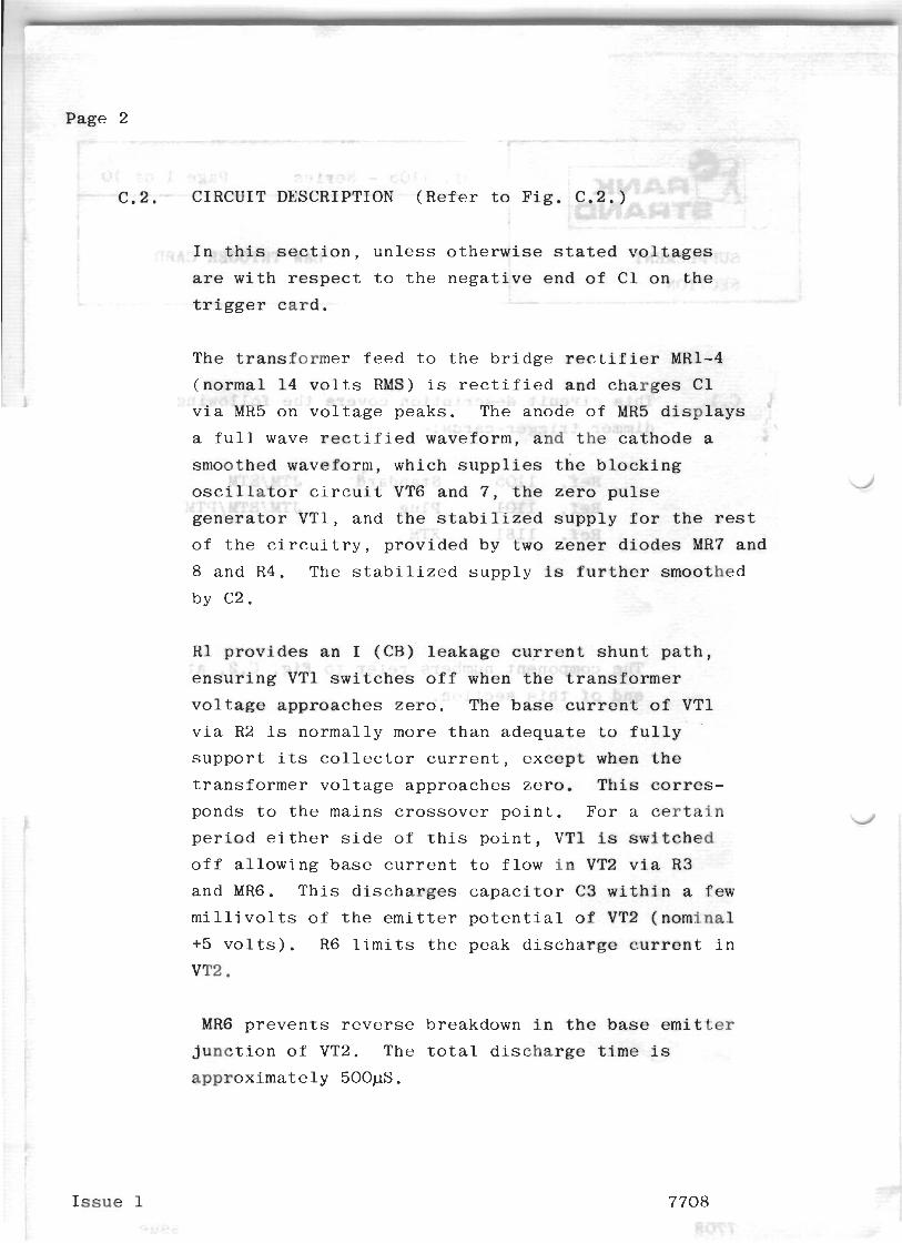
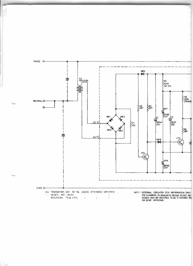
CIRCUIT DESCRIPTION ( R e f e r
I n t h i s s e c t i o n , u n l e s s o t h e r w i s e s t a t e d v o l t a g e s
are w i t h r e s p e c t t o t h e n e g a t i v e e n d o f C1 o n t h e
t r i g g e r c a r d .
The t r a n s f o r m e r f e e d t o t h e b r i d g e r e c t i f i e r MR1-4
( n o r m a l 1 4 v o l t s RMS) is r e c t i f i e d and c h a r g e s C1
v i a MR5 o n v o l t a g e p e a k s . The anode o f MR5 d i s p l a y s
a f u l l wave r e c t i f i e d waveform, and t h e c a t h o d e a
smoothed waveform, which s u p p l i e s t h e b l o c k i n g
o s c i l l a t o r c i r c u i t VT6 and 7 , t h e z e r o p u l s e d
g e n e r a t o r VT1, and t h e s t a b i l i z e d s u p p l y f o r t h e rest
o f t h e c i r c u i t r y , p r o v i d e d by t w o z e n e r d i o d e s MR7 and
8 and R4. The s t a b i l i z e d s u p p l y is f u r t h e r smoothed
by C2.
R1 provides an I (CB) leakage c u r r e n t s h u n t p a t h ,
e n s u r i n g VT1 s w i t c h e s o f f when t h e t r a n s f o r m e r
v o l t a g e a p p r o a c h e s z e r o . The b a s e c u r r e n t o f VT1
v i a R2 is n o r m a l l y more t h a n a d e q u a t e t o f u l l y
s u p p o r t its c o l l e c t o r c u r r e n t , e x c e p t when t h e
t r a n s f o r m e r v o l t a g e a p p r o a c h e s z e r o . T h i s corres-
ponds t o t h e m a i n s c r o s s o v e r p o i n t . F o r a c e r t a i n
p e r i o d e i t h e r s i d e o f t h i s p o i n t , VTl is s w i t c h e d
o f f a l l o w i n g b a s e c u r r e n t t o f l o w i n VT2 v i a R3
and MR6. T h i s d i s c h a r g e s c a p a c i t o r C 3 w i t h i n a few
m i l l i v o l t s o f t h e emitter p o t e n t i a l of YT2 ( n o m i n a l
+5 v o l t s ) . R6 l i m i t s t h e peak d i s c h a r g e c u r r e n t i n
MR6 p r e v e n t s r e v e r s e breakdown i n t h e b a s e emitter
j u n c t i o n o f VT2. The t o t a l d i s c h a r g e t i m e is
a p p r o x i m a t e l y 500pS.
I s s u e 1 7708
Page 3
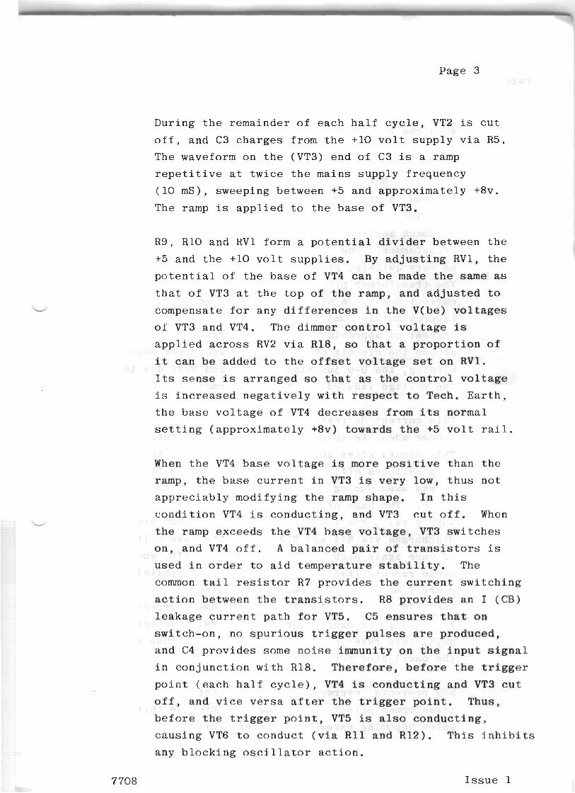
D u r i n g t h e r e m a i n d e r o f e a c h h a l f c y c l e , VT2 is c u t
o f f , and C3 c h a r g e s f rom t h e +l0 v o l t s u p p l y v i a R 5 .
The waveform o n t h e (VT3) e n d o f C3 is a ramp
r e p e t i t i v e a t t w i c e t h e ma ins s u p p l y f r e q u e n c y
( 1 0 mS), sweep ing be tween +5 and a p p r o x i m a t e l y +8v.
The ramp is a p p l i e d t o t h e b a s e of VT3.
R 9 , R 1 0 and R V 1 fo rm a p o t e n t i a l d i v i d e r be tween t h e
+5 and t h e +l0 v o l t s u p p l i e s . By a d j u s t i n g R V l , t h e
p o t e n t i a l o f t h e b a s e o f VT4 c a n b e made t h e same as t h a t o f VT3 a t t h e t o p o f t h e ramp, and a d j u s t e d to
compensa t e f o r any d i f f e r e n c e s i n t h e V(be ) v o l t a g e s
o f VT3 and VT4. The dimmer c o n t r o l v o l t a g e is
a p p l i e d across RV2 v i a R 1 8 , so t h a t a p r o p o r t i o n o f
i t c a n b e added t o t h e o f f s e t v o l t a g e set o n RV1.
Its s e n s e is a r r a n g e d so t h a t as t h e c o n t r o l v o l t a g e
is i n c r e a s e d n e g a t i v e l y w i t h r e s p e c t t o Tech . E a r t h ,
t h e b a s e v o l t a g e o f VT4 d e c r e a s e s f rom its normal
s e t t i n g ( a p p r o x i m a t e l y +8v) t o w a r d s t h e +5 v o l t r a i l .
When t h e VT4 b a s e v o l t a g e is more p o s i t i v e t h a n t h e
ramp, t h e b a s e c u r r e n t i n VT3 is v e r y l o w , t h u s n o t
a p p r e c i a b l y m o d i f y i n g t h e ramp s h a p e . I n t h i s
c o n d i t i o n VT4 i s c o n d u c t i n g , and VT3 c u t o f f . When L
t h e ramp e x c e e d s t h e VT4 b a s e v o l t a g e , VT3 s w i t c h e s
o n , and VT4 o f f . A b a l a n c e d p a i r o f t r a n s i s t o r s is
u s e d i n o r d e r t o a i d t e m p e r a t u r e s t a b i l i t y . The
common t a i l resistor R7 p r o v i d e s t h e c u r r e n t s w i t c h i n g
a c t i o n be tween t h e t r a n s i s t o r s . R 8 p r o v i d e s a n I ( C B )
l e a k a g e c u r r e n t p a t h f o r VT5. C5 e n s u r e s t h a t o n
s w i t c h - o n , no s p u r i o u s t r i g g e r p u l s e s are p r o d u c e d ,
a n d C4 p r o v i d e s some n o i s e immunity o n t h e i n p u t s i g n a l
i n c o n j u n c t i o n w i t h R 1 8 . T h e r e f o r e , before t h e t r i g g e r
p o i n t ( e a c h h a l f c y c l e ) , VT4 is c o n d u c t i n g a n d VT3 c u t
o f f , and v i c e v e r s a a f t e r t h e t r i g g e r p o i n t . Thus,
b e f o r e t h e t r i g g e r p o i n t , VT5 is a l so c o n d u c t i n g ,
c a u s i n g VT6 t o c o n d u c t ( v i a R 1 1 and R12) . T h i s i n h i b i t s
any b l o c k i n g o s c i l l a t o r a c t i o n .
7708 I s s u e 1
Page 4
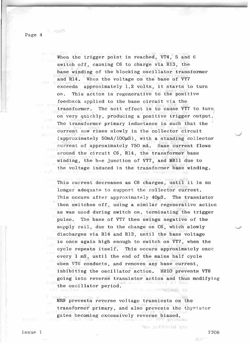
When the trigger point is reached, VT4, 5 and 6
switch off, causing C6 to charge via R13, the
base winding of the blocking oscillator transformer
and R14. When the voltage on the base of VT7
exceeds approximately 1.2 volts, it starts to turn
on. This action is regenerative to the positive
feedback applied to the base circuit via the
transformer. The nett effect is to cause VT7 to turn
on very quickly, producing a positive trigger output.
The transformer primary inductance is such that the
current now rises slowly in the collector circuit d
(approximately 50mA/100pS), with a standing collector
current of approximately 750 mA. Base current flows
around the circuit C6, R14, the transformer base
winding, the b-e junction of VT7, and MRll due to
the voltage induced in the transformer base winding.
This current decreases as C6 charges, until it is no
longer adequate to support the collector current.
This occurs after approximately 40pS. The transistor
then switches off, using a similar regenerative action
as was used during switch on, terminating the trigger
pulse. The base of VT7 then swings negative of the
supply rail, due to the change on C6, which slowly d
discharges via R14 and R13, until the base voltage
is once again high enough to switch on VT7, when the
cycle repeats itself. This occurs approximately once
every 1 mS, until the end of the mains half cycle
when VT6 conducts, and removes any base current,
inhibiting the oscillator action. MRlO prevents VT6
going into reverse transistor action and thus modifying
the oscillator period.
MR9 prevents reverse voltage transients on the
transformer primary, and also prevents the thyristor
gates becoming excessively reverse biased.
Issue 1 7 708
P a g e 5
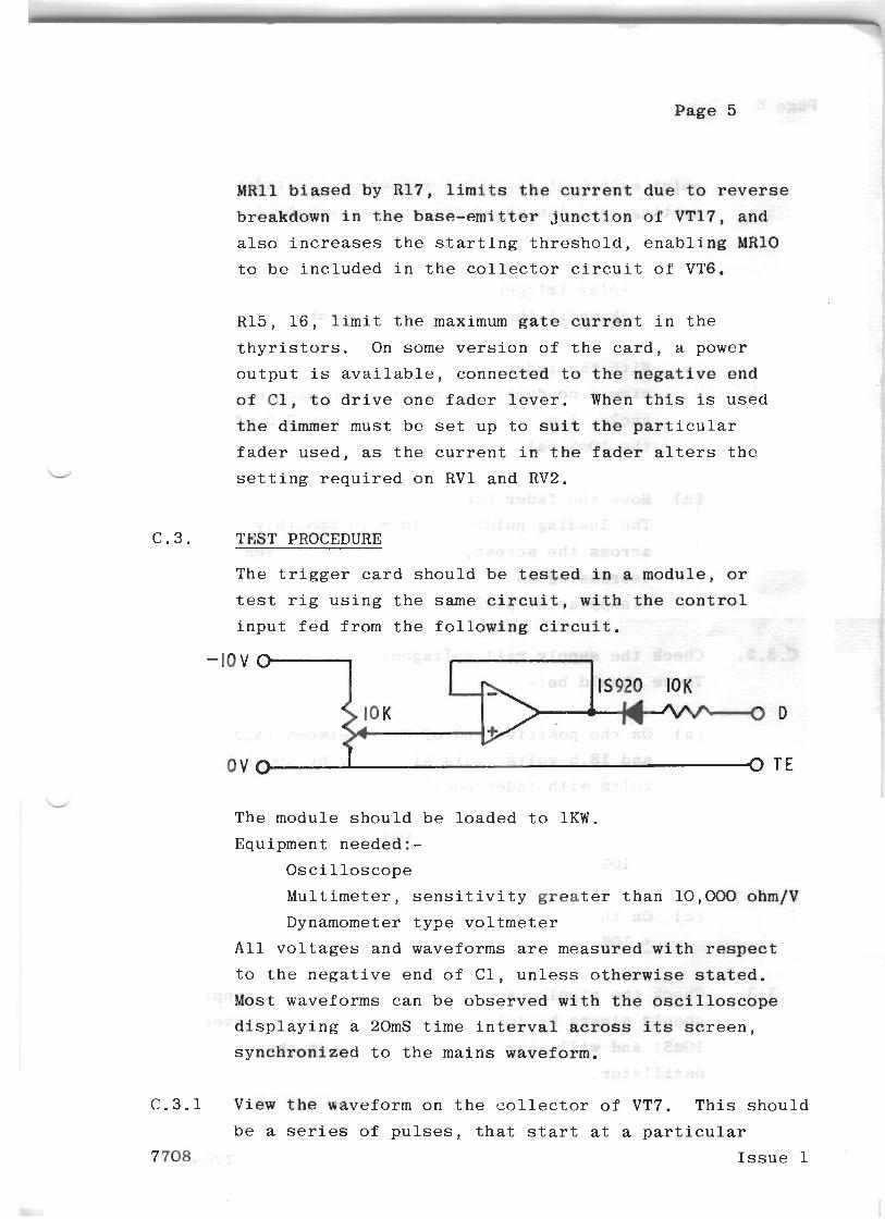
MRll biased by R17, l i m i t s t h e c u r r e n t d u e t o r e v e r s e
breakdown i n t h e base-emitter j u n c t i o n o f VT17, a n d
a l s o i n c r e a s e s t h e s t a r t i n g t h r e s h o l d , e n a b l i n g MRlO
t o be i n c l u d e d i n t h e c o l l e c t o r c i r c u i t o f VT6.
R15, 1 6 , l i m i t t h e maximum g a t e c u r r e n t i n t h e
t h y r i s t o r s . On some v e r s i o n o f t h e c a r d , a power
o u t p u t is a v a i l a b l e , c o n n e c t e d t o t h e negative e n d
of Cl, t o d r i v e o n e f a d e r l e v e r . When t h i s is u s e d
t h e dimmer mus t be se t u p t o s u i t t h e p a r t i c u l a r
f a d e r u s e d , as t h e c u r r e n t i n t h e f a d e r a l t e r s t h e
s e t t i n g r e q u i r e d o n R V 1 a n d RV2.
C . 3 . TEST PROCEDURE
The t r i g g e r c a r d s h o u l d be t e s t e d i n a m o d u l e , o r
tes t r i g u s i n g t h e s a m e c i r c u i t , w i t h t h e c o n t r o l
i n p u t f e d f r o m t h e f o l l o w i n g c i r c u i t .
The m o d u l e s h o u l d be l o a d e d t o 1 K W .
Equ ipment n e e d e d : -
O s c i l l o s c o p e
M u l t i m e t e r , s e n s i t i v i t y greater t h a n 10,000 ohm/V
Dynamometer t y p e v o l t m e t e r
A l l v o l t a g e s a n d waveforms are m e a s u r e d w i t h r e s p e c t
t o t h e n e g a t i v e e n d o f C l , u n l e s s o t h e r w i s e s t a t e d ,
Most w a v e f o r m s c a n be o b s e r v e d w i t h the o s c i l l o s c o p e
d i s p l a y i n g a 20mS t i m e i n t e r v a l across i t s s c r e e n ,
s y r i c h r b n i Z e d t o t h e m a i n s waveform,
C . 3 . 1 V i e w t h e waveform o n t h e c o l l e c t o r o f VT7. T h i s s h o u l d
be a series o f p u l s e s , t h a t s t a r t a t a p a r t i c u l a r
7 708 I s s u e 1
~ U ~ I I G each h a l f c y c l e de te rmined by t h e f a d e r
s e t t i n g , and f i n i s h a t t h e end of each h a l f c y c l e .
( a ) With t h e f a d e r a t z e r o , a d j u s t R V 1 t o
d i s p l a y t r i g g e r p u l s e s , and t h e n t u r n i t
back u n t i l t h e p u l s e s j u s t v a n i s h .
( b ) With t h e f a d e r se t a t f u l l , a d j u s t RV2 t o
g i v e a conduc t ion t i m e of 7.5mS each h a l f
c y c l e , i . e . s o t h a t p u l s e s occupy 7 .5 of
t h e lOmS h a l f c y c l e l e n g t h .
( c ) Move t h e f a d e r e v e n l y from f u l l t o o u t .
The l e a d i n g p u l s e shou ld move smoothly
a c r o s s t h e screen, the number of p u l s e s
d e c r e a s i n g as i t d o e s , u n t i l a l l p u l s e s
d i s a p p e a r a t p o s i t i o n z e r o .
C.3.2. Check t h e s u p p l y r a i l v o l t a g e s .
These s h o u l d be:-
( a ) On t h e p o s i t i v e e n d of Cl: Between 13.5
and 18.5 v o l t s ( T h i s w i l l v a r y by abou t 2
v o l t s w i t h f a d e r p o s i t i o n ) .
( b ) On t h e p o s i t i v e end o f M R 7 : 10.2 v o l t s
( c ) On t h e p o s i t i v e end o f MR8: 5.1 v o l t s
Check t h e r i p p l e on t h e s u p p l y r a i l s . The r i p p l e
s h o u l d a lways b e f u l l wave ( i . e . r e p e t i t i v e e v e r y
10mS) and w i l l a l s o show s p i k e s due to t h e
osc i l l a to r .
I s s u e 1 7708
P a g e 7
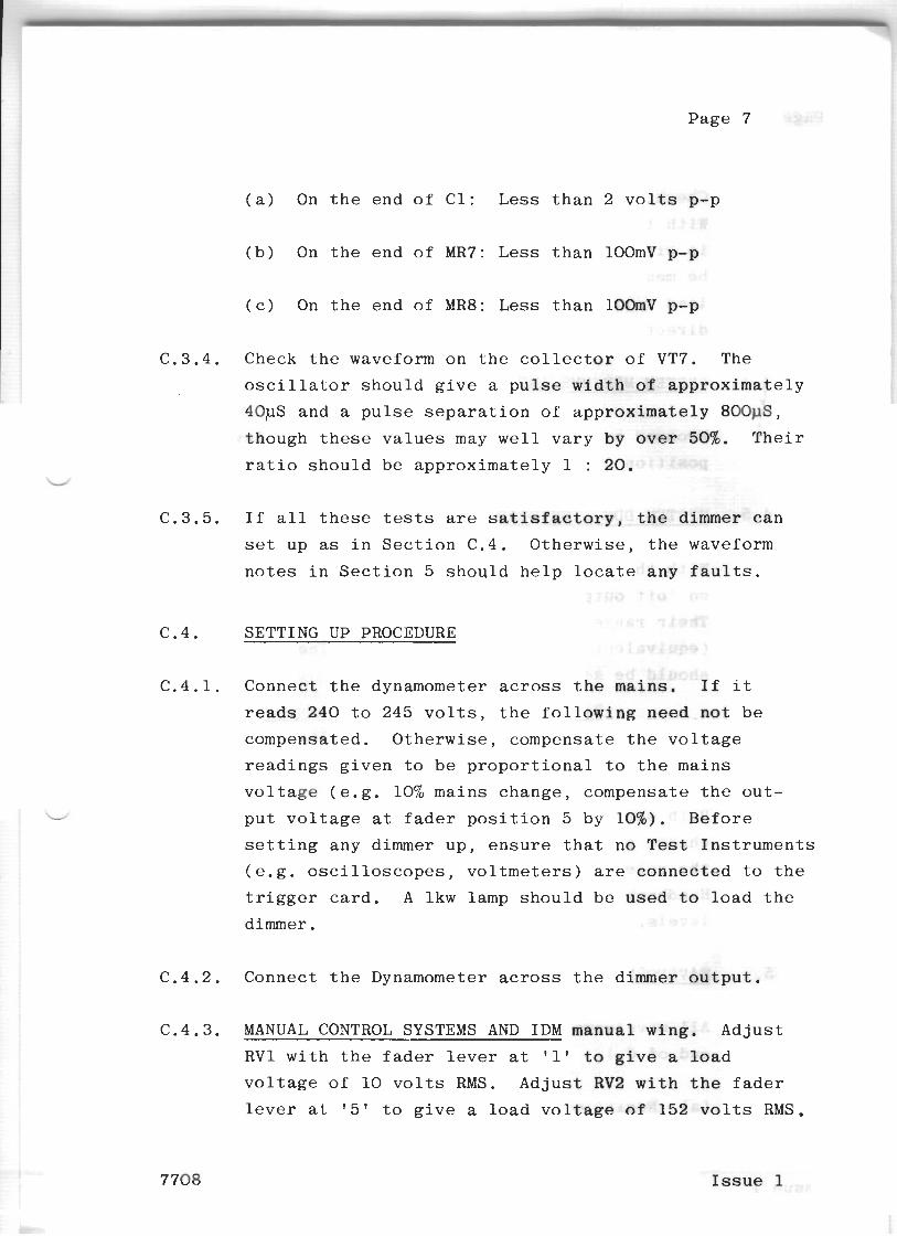
( a ) On t h e e n d o f C l : L e s s t h a n 2 v o Its p-p
( b ) On t h e e n d o f MR7: L e s s t h a n lOOmV p-p
( c ) On t h e e n d o f MR8: L e s s t h a n 1BOrnV p-p
Check t h e waveform o n t h e col lector o f VT7. The
o s c i l l a t o r s h o u l d g i v e a p u l s e w i d t h o f a p p r o x i m a t e l y
40pS a n d a p u l s e s e p a r a t i o n o f a p p r o x i m a t e l y 800pS,
t h o u g h t h e s e v a l u e s may w e l l v a r y b y o v e r 50%. T h e i r
r a t i o s h o u l d b e a p p r o x i m a t e l y 1 : 20.
I f a l l t h e s e tests are s a t i s f a c t o r y , t h e dimmer c a n
set u p as i n S e c t i o n C . 4 . O t h e r w i s e , t h e waveform
n o t e s i n S e c t i o n 5 s h o u l d h e l p locate a n y f a u l t s .
SETTING UP PROCEDURE
C o n n e c t t h e dynamomete r across t h e m a i n s . I f i t
r e a d s 2 4 0 t o 245 v o l t s , t h e f o l l o w f n g need not b e
c o m p e n s a t e d . O t h e r w i s e , c o m p e n s a t e t h e v o l t a g e
r e a d i n g s g i v e n t o b e p r o p o r t i o n a l t o t h e m a i n s
v o l t a g e ( e . g . 10% m a i n s c h a n g e , c o m p e n s a t e t h e o u t -
p u t v o l t a g e a t f a d e r p o s i t i o n 5 b y 1 0 % ) . B e f o r e
s e t t i n g a n y dimmer u p , e n s u r e t h a t n o Test I n s t r u m e n t s
( e . g . o s c i l l o s c o p e s , v o l t m e t e r s ) are c o n n e c t e d t o t h e
t r i g g e r c a r d . A lkw lamp s h o u l d b e used t o l o a d t h e
dimmer.
C o n n e c t t h e Dynamometer across t h e dimmer o u t p u t .
MANUAL CONTROL SYSTEMS AND IDM manual w i n g . A d j u s t
RV1 w i t h t h e f a d e r l e v e r a t '1' t o g i v e a l o a d
v o l t a g e o f 10 v o l t s RMS. A d j u s t RV2 w i t h the f a d e r
l e v e r a t ' 5 ' t o g i v e a l o a d v o l t a g e of 1 5 2 v o l t s RMS.
I s s u e 1
Page 8
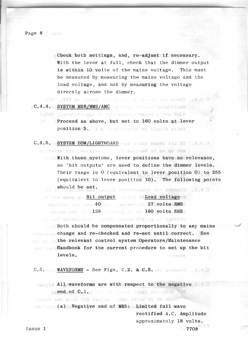
Check both s e t t i n g s , a n d , r e - a d j u s t i f n e c e s s a r y .
With t h e l e v e r a t f u l l , c h e c k t h a t t h e dimmer o u t p u t
is w i t h i n 10 v o l t s o f t h e ma ins v o l t a g e . T h i s must
b e measured by m e a s u r i n g t h e ma ins v o l t a g e and t h e
l o a d v o l t a g e , and n o t by m e a s u r i n g t h e v o l t a g e
d i r e c t l y a c r o s s t h e dimmer.
C.4.4 . SYSTEM MSR/MMS/AMC
P r o c e e d as above , b u t se t t o 1 6 0 v o l t s a t l e v e r
p o s i t i o n 5.
C.4.5 . SYSTEM DDM/LIGHTBOARD
With t h e s e s y s t e m s , l e v e r p o s i t i o n s h a v e no r e l e v a n c e ,
s o ' b i t o u t p u t s ' a r e u s e d t o d e f i n e t h e dimmer l e v e l s .
T h e i r r a n g e is 0 ( e q u i v a l e n t t o l e v e r p o s i t i o n 0 ) t o 255
( e q u i v a l e n t t o l e v e r p o s i t i o n 1 0 ) . The f o l l o w i n g p o i n t s
s h o u l d be set.
B i t o u t p u t Load v o l t a g e
4 0 27 v o l t s RMS
128 1 6 0 v o l t s RMS
Bo th s h o u l d be compensa t ed p r o p o r t i o n a l l y t o any m a i n s 4'
change and r e - checked ahd re-set u n t i l c o r r e c t . S e e
t h e r e l e v a n t c o n t r o l s y s t e m O p e r a t o r s / M a i n t e n a n c e
Handbook far t h e current p r o c e d u r e t o set up t h e b i t
l e v e l s .
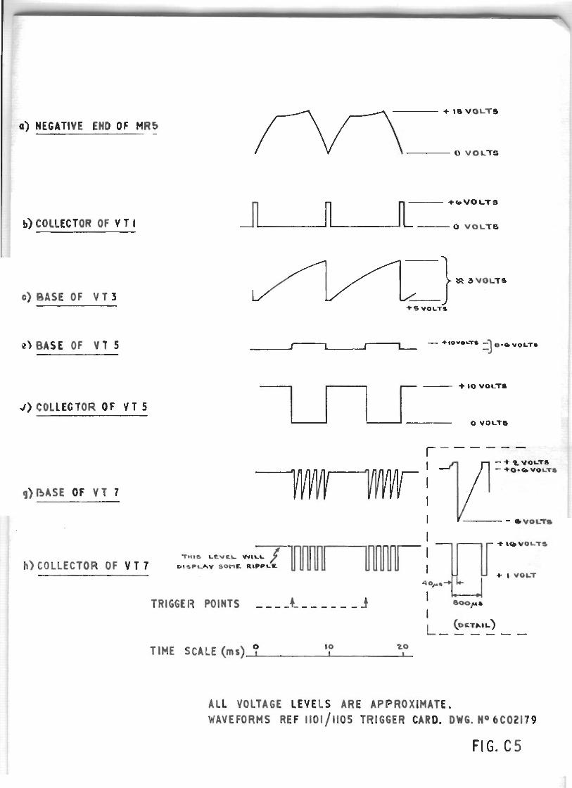
C.5. WAVEFORMS - S e e F i g s . C.2. & C.5.
A l l waveforms a r e w i t h r e s p e t
e n d o f C . l .
( a ) N e g a t i v e end of MR5: L i m i t e d full wave
rec t i f ied A . C . Ampl i t ude
a p p r o x i m a t e l y 18 v o l t s .
I s s u e 1 7708
Page 9
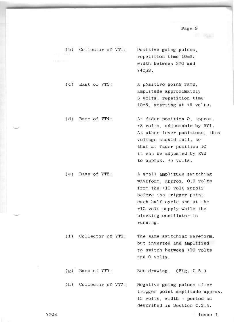
(b) Collector of VT1: Positive going pulses,
repetition time 10mS.
width between 370 and
74OpS.
(c) East of VT3: A positive going ramp,
amplitude approximately
3 volts, repetition time
lOmS, starting at +5 volts.
(d) Base of VT4 : At fader position 0, approx.
+8 volts, adjustable by RV1.
At other lever positions, this
voltage should fall, so
that at fader position 10
it can be adjusted by RV2
to approx. +5 volts.
(e) Base of VT5: A small amplitude switching
waveform, approx. 0.6 volts
from the +l0 volt supply
before the trigger point
each half cycle and at the
+l0 volt supply while the
blocking oscillator is
running.
( f ) Collector of VT5: The same switching waveform,
but inverted and amplified
to switch between +l0 volts
and 0 volts.
(g) Base of VT7: See drawing. (Fig, C.5.)
(h) Collector of VT7: Negative going pulses after
trigger point amplitude approx.
15 volts, width - period as described in Section C . 3 . 4 .
7708 Issue 1
Page 10
( j ) Each t r i g g e r p u l s e P o s i t i v e g o i n g p u l s e s ,
o u t p u t : a m p l i t u d e a p p r o x i m a t e l y
3 v o l t s , be tween e a c h
p a i r o f g a t e - c a t h o d e
o u t p u t s .
Beware - The g a t e and c a t h o d e o u t p u t s , R 5 and R6
a r e a t Mains p o t e n t i a l .
I s s u e l 7708
LOAD 0
ALL TRANSISTORS ARE BC l 8 4 UNLESS OTHERWISE SPECIFIED MITE:- EXTERNAL C~RCUITRV FOR IWO!4M4flDN ONLY DIODES ARE 15920 PIN N U M E % IN BRACKETS REFER TO REF )%l RESl STORS "4 W + 5 % OlOMS MAY BE REFERED TO AS 'O'AATHER TH/
ON SOME VERSQNS
d CONTROL TE( EARTH
CIRCUIT DIAGRAM 1105 -SERIES - S-LAW DIMMER TRIGGER CARD
ClRCVlT RELEVANT TO THE FOLLWING TRIGGER CARDS R f f 1101 REF 1105 REF 7187
n FILTER
1 1 - TRX 2019 S1 WHITE
FIG. C 2
+ l8 VOLTS
\TIVE EHD OF MR5
0 VOLTS
+*VOLTS
0 VOLTS
c) BASE OF V T 3
J ) COLLECTOR OF V T 5
g) DASE OF V T 7
COLLECTOR OF V T 7
1- + 1 0 VOLTS
0 V O L T 6
- + t VOLTS ' +O- b VOLTS
TIME SCALE (ms) ? 10 I t o l
ALL VOLTAGE LEVELS ARE APPROXIMATE. WAVEFORMS REF 1101/1105 TRIGGER CARD. DW6. No 6C02179
FIG. C 5
I I
SUPPLEMENT
SECTION
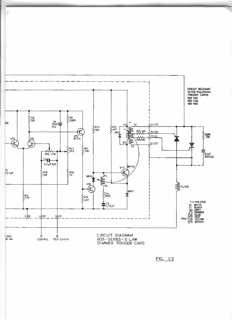
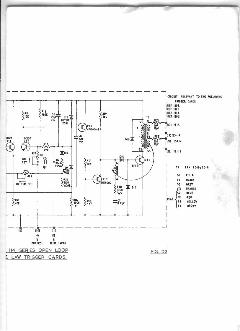
Ref. 1114 Series S 4 Square Law Trigger Cards
D.1. This circuit description covers the following
open-loop square law dimmer trigger cards:
Ref. 1114 - TM Dimmers
Ref. 1115 - JTM/STM Dimmers
Ref. 1116 - JTM/STM/PTM Dimmers (plug in)
Ref. 1192 - XTM Dimers
The component numbers refer to Fig. D.2. at the
end of this section.
7708 Issue 1
Page 2
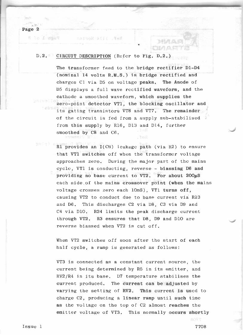
CIRCUIT DESCRIPl
The t r a n s f o r m e r
( n o m i n a l 14 v o l l
c h a r g e s C 1 v i a I
c a t h o d e a smoothed waveform, which s u p p l i e s t h e
zero-point d e t e c t o r VT1, t h e b l o c k i n g o s c i l l a t o r and
i t s g a t i n g t r a n s i s t o r s VT8 and VT7. The r e m a i n d e r
o f t h e c i r c u i t i s f e d f rom a s u p p l y s u b - s t a b i l i s e d
f rom t h i s s u p p l y by R16, D13 and D14, f u r t h e r
smoothed by C8 and C6.
R 1 p r o v i d e s a n I (CB) l e a k a g e p a t h ( v i a R2) t o e n s u r e
t h a t VT1 s w i t c h e s o f f when t h e t r a n s f o r m e r v o l t a g e
a p p r o a c h e s z e r o . D u r i n g t h e m a j o r p a r t o f t h e ma ins
c y c l e , VT1 i s c o n d u c t i n g , r e v e r s e - b i a s s i n g D6 and
p r o v i d i n g no b a s e c u r r e n t t o VT2. F o r about 200pS
e a c h s i d e o f t h e m a i n s c r o s s o v e r p o i n t (when t h e ma ins
v o l t a g e crosses z e r o e a c h lOmS), VT1 t u r n s off,
c a u s i n g VT2 t o c o n d u c t due t o b a s e c u r r e n t v i a R23
and D6. T h i s d i s c h a r g e s C2 v i a D 8 , C3 v i a D9 a n d
C4 v i a D 1 0 . R24 l i m i t s t h e p e a k d i s c h a r g e c u r r e n t
t h r o u g h VT2. R 3 e n s u r e s t h a t D 8 , D9 and D 1 0 are J r e v e r s e b i a s s e d when VT2 i s c u t o f f .
When VT2 s w i t c h e s o f f soon a f t e r t h e s tart of e a c h
h a l f c y c l e , a ramp i s g e n e r a t e d a s f o l l o w s :
VT3 is c o n n e c t e d as a c o n s t a n t c u r r e n t s o u r c e , t h e
c u r r e n t b e i n g d e t e r m i n e d by R 5 i n i ts emitter, and
RV2/R4 i n i ts b a s e . D7 t e m p e r a t u r e s t a b i l i s e s t h e
c u r r e n t p roduced . The c u r r e n t c a n b e a d j u s t e d by
v a r y i n g t h e s e t t i n g o f RV2. T h i s c u r r e n t i s u s e d t o
c h a r g e C2, p r o d u c i n g a l i n e a r ramp u n t i l s u c h t i m e
a s t h e v o l . t a g e on t h e t o p o f C2 almost r e a c h e s t h e
emitter v o l t a g e o f VT3. T h i s n o r m a l l y o c c u r s s h o r t l y
I s s u e 1 7 708
Page 3
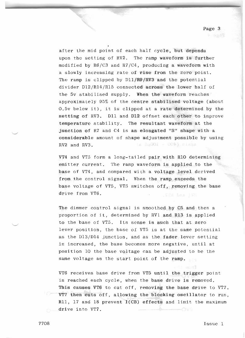
after the mid point of each half cycle, but depends
upon the setting of RV2. The ramp waveform is further
modified by R6/C3 and R7/C4, producing a waveform with
a slowly increasing rate of rise from the zero point.
The ramp is clipped by Dll/R9/RV3 and the potential
divider D12/R14/R15 connected across the lower half of
the 5v stabilised supply. When the waveform reaches
approximately 95% of the centre stabilised voltage (about
0 . 5 ~ below it), it is clipped at a rate determined by the
setting of RV3. D11 and D12 offset each other to improve
temperature stability. The resultant waveform at the
junction of R7 and C4 is an elongated "S" shape with a
considerable amount of shape adjustment possible by using
RV2 and RV3.
VT4 and VT5 form a long-tailed pair with R10 determining
emitter current. The ramp waveform is applied to the
base of VT4, and compared with a voltage level derived
from the control signal. When the ramp exceeds the
base voltage of VT5, VT5 switches off, removing the base
drive from VT6.
The dimmer control signal is smoothed by C5 and then a '
proportion of it, determined by RV1 and R13 is applied
to the base of VT5. Its sense is such that at zero
lever position, the base of VT5 is at the same potential
as the D13/D14 junction, and as the fader lever setting
is increased, the base becomes more negative, until at
position 10 the base voltage can be adjusted to be the
same voltage as the start point of the ramp.
VT6 receives base drive from VT5 until the trigger point
is reached each cycle, when the base drive is removed.
This causes VT6 to cut off, removing the base drive to VT7.
VT7 then cuts off, allowing the blocking oscillator to run,
R11, 17 and 18 prevent I(CB) effects and limit the maximum
drive into VT7.
7708 Issue 1
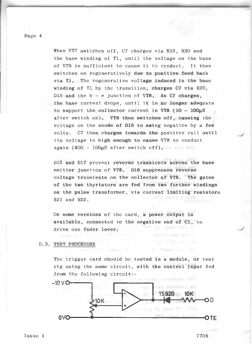
When VT7 s w i t c h e s o f f , C7 c h a r g e s v i a R19, R20 a n d
t h e b a s e w i n d i n g o f T 1 , u n t i l t h e v o l t a g e o n t h e b a s e
o f VT8 is s u f f i c i e n t t o c a u s e i t t o c o n d u c t . I t t h e n
s w i t c h e s o n r e g e n e r a t i v e l y d u e t o p o s i t i v e feed back
v i a T1. The r e g e n e r a t i v e v o l t a g e i n d u c e d i n t h e b a s e
w i n d i n g o f T 1 by t h e t r a n s i t i o n , c h a r g e s C7 v i a R20,
D15 a n d t h e b - e j u n c t i o n o f VT8. A s C7 charges,
t h e base c u r r e n t d r o p s , u n t i l i t is n o l o n g e r a d e q u a t e
t o s u p p o r t t h e c o l l e c t o r c u r r e n t i n VT8 (l0 - 100~15
a f t e r s w i t c h o n ) . VT8 t h e n s w i t c h e s o f f , c a u s i n g t h e
v o l t a g e o n t h e a n o d e of D 1 5 t o s w i n g n e g a t i v e by a few
v o l t s . C7 t h e n c h a r g e s t o w a r d s t h e p o s i t i v e r a i l u n t i l 4
its v o l t a g e is h i g h enough t o cause VT8 t o c o n d u c t
a g a i n ( 4 0 0 - lOOpS a f t e r s w i t c h o f f ) .
D 1 5 a n d D 1 7 p r e v e n t r e v e r s e t r a n s i e n t s across t h e base
emitter j u n c t i o n o f VT8. D16 s u p p r e s s e s r e v e r s e
v o l t a g e t r a n s i e n t s on t h e c o l l e c t o r of VT8. The gates
of t h e two t h y r i s t o r s are f e d f r o m two f u r t h e r w i n d i n g s
o n t h e p u l s e t r a n s f o r m e r , v i a c u r r e n t l i m i t i n g r e s i s t o r s
R21 a n d R22.
l
On some v e r s i o n s o f t h e card, a power o u t p u t is
a v a i l a b l e , c o n n e c t e d t o t h e n e g a t i v e e n d o f C l , t o
d r i v e o n e f a d e r l e v e r .
D. 3 . TEST PROCEDURE
The t r i gge r c a r d s h o u l d be t e s t e d i n a m o d u l e , o r t e s t
r i g u s i n g t h e same c i r c u i t , w i t h t h e c o n t r o l i n p u t f e d
f r o m t h e f o l l o w i n g c i r c u i t : -
I s s u e 1
OVO A OTE
P a g e 5
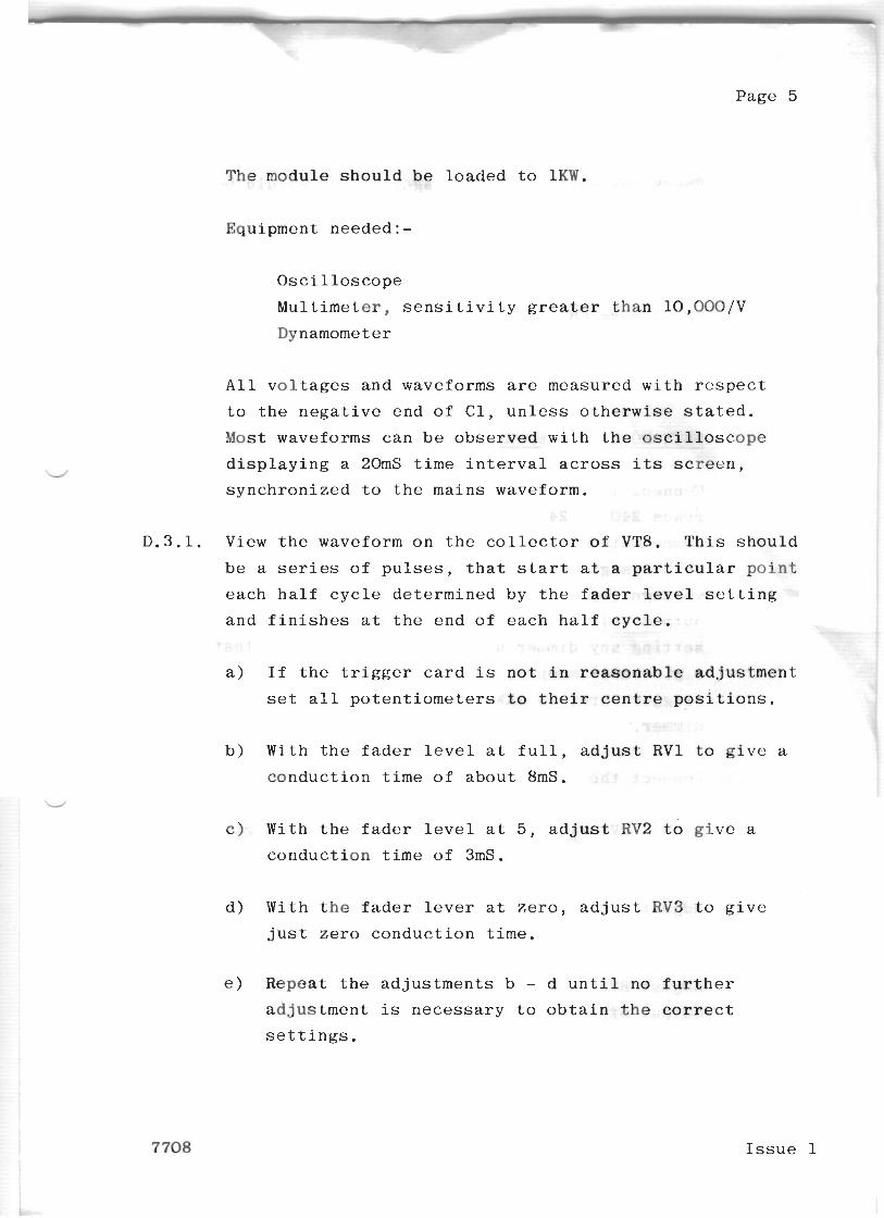
T h e m o d u l e s h o u l d b e l o a d e d t o 1 K W .
Equ ipment n e e d e d : -
O s c i l l o s c o p e
M u l t i m e t e r , s e n s i t i v i t y g r e a t e r t h a n 10 ,00O/V
Dynamometer
A l l v o l t a g e s a n d w a v e f o r m s are m e a s u r e d w i t h r e s p e c t
t o t h e n e g a t i v e e n d o f C l , u n l e s s o t h e r w i s e s t a t e d .
Most w a v e f o r m s c a n b e o b s e r v e d w i t h t h e o s c i l l o s c o p e
d i s p l a y i n g a 20mS t i m e i n t e r v a l across i ts s c r e e n ,
s y n c h r o n i z e d t o t h e m a i n s waveform.
D . 3 . 1 . V i e w t h e waveform o n t h e c o l l e c t o r of VT8. T h i s s h o u l d
b e a series o f p u l s e s , t h a t s t a r t a t a p a r t i c u l a r p o i n t
e a c h h a l f c y c l e d e t e r m i n e d b y t h e f a d e r l e v e l s e t t i n g
a n d f i n i s h e s a t t h e e n d o f e a c h h a l f c y c l e .
a ) I f t h e t r i g g e r c a r d i s not i n r e a s o n a b l e a d j u s t m e n t
s e t a l l p o t e n t i o m e t e r s t o t h e i r c e n t r e p o s i t i o n s .
b ) W i t h t h e f a d e r l e v e l a t f u l l , a d j u s t R V 1 t o g i v e a
c o n d u c t i o n t i m e o f a b o u t 8mS.
c ) Wi th t h e f a d e r l e v e l a t 5 , a d j u s t RV2 t o g i v e a
c o n d u c t i o n t i m e o f 3mS.
d ) W i t h t h e f a d e r l e v e r a t z e r o , a d j u s t R V 3 t o g i v e
j u s t z e r o c o n d u c t i o n t i m e .
e ) R e p e a t t h e a d j u s t m e n t s b - d u n t i l no f u r t h e r
a d j u s t m e n t is n e c e s s a r y t o o b t a i n the correct
s e t t i n g s .
7 708 I s s u e 1
Page 6
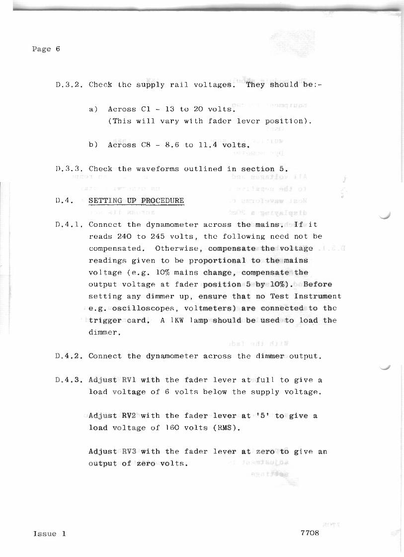
D.3.2. Check the supply rail voltages. They should be:-
a) Across C1 - 13 to 20 volts. (This will vary with fader lever position).
b) Across C8 - 8.6 to 11.4 volts.
D.3.3. Check the waveforms outlined in section 5.
D.4. SETTING UP PROCEDURE
D.4.1. Connect the dynamometer across the mains. If it
reads 240 to 245 volts, the following need not be
compensated. Otherwise, compensate the voltage
readings given to be proportional to the mains
voltage (e.g. 10% mains change, compensate the
output voltage at fader position 5 by 10%). Before
setting any dimmer up, ensure that no Test Instrument
e.g. oscilloscopes, voltmeters) are connected to the trigger card. A 1KW lamp should be used to load the
dimmer.
D.4.2. Connect the dynamometer across the dimmer output.
D.4.3. Adjust RV1 with the fader lever at full to give a
load voltage of 6 volts below the supply voltage.
Adjust RV2 with the fader lever at '5' to give a
load voltage of 160 volts (RMS).
Adjust RV3 with the fader lever at zero to give an
output of zero volts.
Issue 1 7708
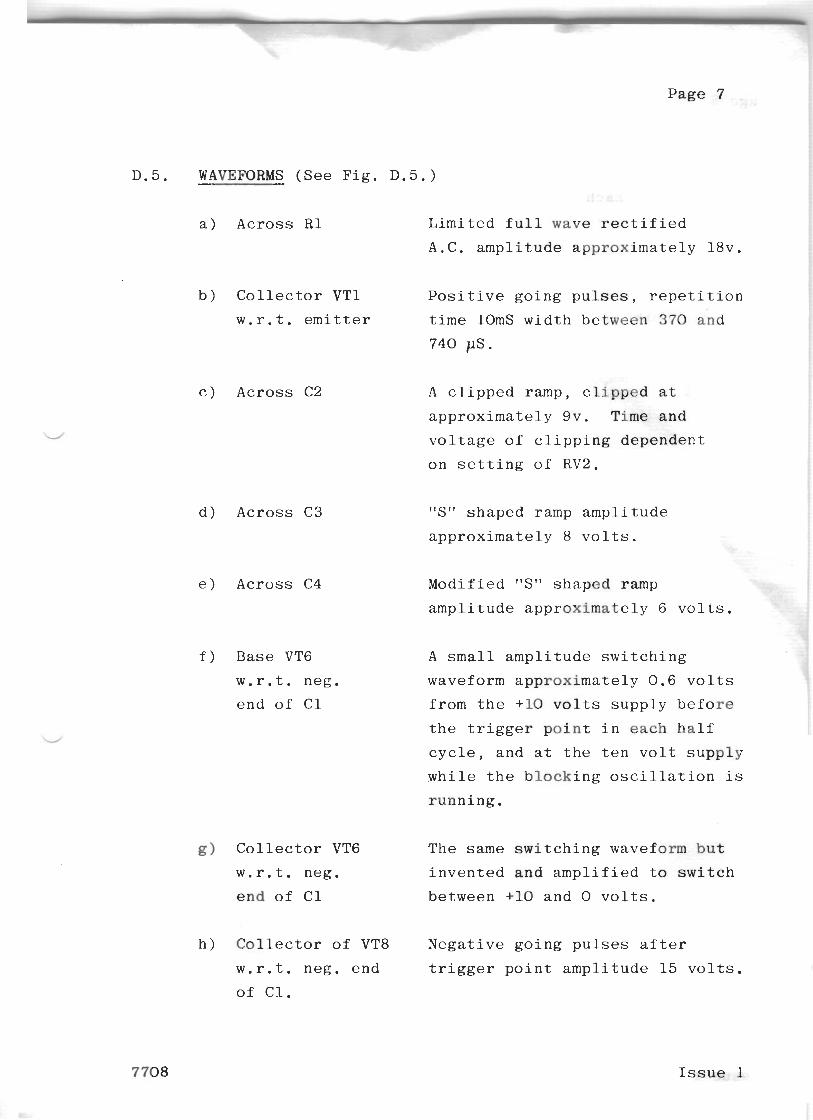
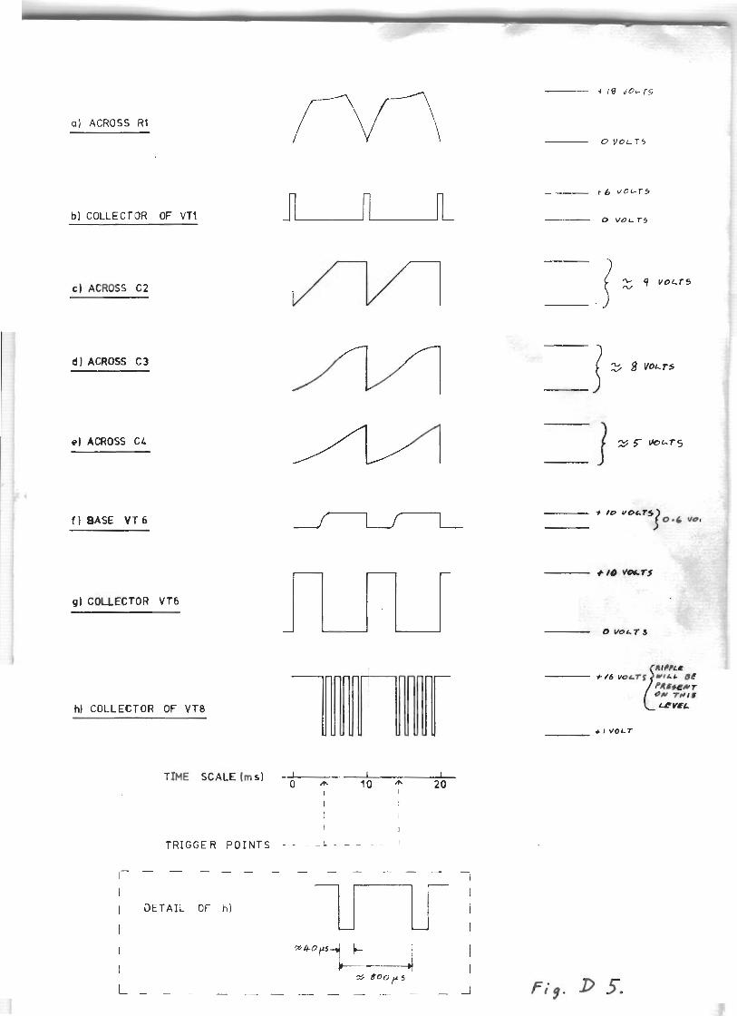
D. 5. WAVEFORMS (See Fi
a) Across R1
b) Collector VTI
w.r.t. emitter
c) Across C2
d) Across C3
e) Across C4
f) Base VT6
w.r.t. neg.
end of C1
g) Collector VT6
w.r.t. neg.
end of C1
h) Collector of VT8
w.r.t. neg. end
of Cl.
time lOmS width between 370 and
740 PS.
A clipped ramp, clipped at
approximately 9v. Time and
voltage of clipping dependent
on setting of RV2.
"S" shaped ramp amplitude
approximately 8 volts.
Modified "S" shaped ramp
amplitude approximately 6 volts.
A small.amplitude switching
waveform approximately 0.6 volts
from the +l0 volts supply before
the trigger point in each half
cycle, and at the ten volt supply
qhile the blocking oscillation is
running.
The same switching waveform but
invented and amplified to switch
between +l0 and 0 volts.
Negative going pulses after
trigger point amplitude 15 volts.
7708 Issue 1
Page 8
i ) Each t r i g g e r o u t
a p p r o x i m a t e l y 3 volts
between e a c h p a i r of
g a t e - c a t h o d e o u t p u t s .
BEWARE - The g a t e - c a t h o d e o u t p u t s may be a t
mains p o t e n t i a l .
Issue 1 7708
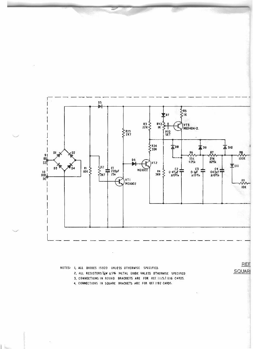
NOTES: I, ALL DIODES I S 9 2 0 UNLESS OTHERWISE SPECIFIED.
2. ALL R E S I S T O R S ~ / ~ W *S% METAL OXIDE UNLESS OTHERWISE SPECIFIED
3, CONNECTIONS I N ROUND BRACKETS ARE FOR REE 1 1 1 5 1 1116 CARDS.
4, CONNECTIONS I N SQUARE BRACKETS ARE FOR REE 1192 CARDS.
I , TR166ER CARD5
I AET 1114. REF 1113 REF I l l 6
T I L f 1192
T I TRX 201812019
S1 WHITE
F! BLACK S3 GREY f 3 ORM6E
fi2 BLUE
(4 1 (6) 3 5
CONTROL TECH. EARTH.
1 1 14 -SERIES OPEN LOOP I LAW TRIGGER CARDS,
FIG. D2
a) ACROSS R1
bl COLLECTOR OF VTl
C ) ACROSS C 2
d ] ACROSS C3
el ACROSS CL
f ) BASE V T 6
g1 C O U E C T O R V T 6
h] COLLECTOR O F VT8
TIME S C A L E h s ] d I I l0 y 2 0
I
T R I G G E R P O I N T S - - - -' - - - - - - ' , _ _ _ _ _ _ _ _ - - - - -
l I D E T A I L OF h )
l
t 6 V O L - T 5
0 V O L T S
+ I V O L T
SCOPE
T h i s h a n d b o o k c o n t a i n s i n f o r m a t i o n n o r m a l l y r e q u i r e d f o r
i n s t a l l a t i o n c o m m i s s i o n i n g a n d m a i n t e n a n c e o f Rank S t r a n d
STN Dimmers a c d t h e i r a s s o c i a l . e d r a c k s .
SERVICE ASSISTANCE
F o r a s s i s t a n c e w i t h s e r v i c i n g o r m a i n t e n a n c e , p l e a s e c o n t a c t
t h e n e a r e s t b r a n c h , a g e n t o r a s s o c i a t e company ( s e e list a t
t h e e n d o f t h i s h a n d b o o k ) a n d s t a t e t h e O r d e r R e f e r e n c e ,
E q u i p m e n t R e f e r e n c e o r o t h e r r e l e v a n t i n f o r m a t i o n as w e l l as
a n i n d i c a t i o n o f a l l f a u l t - s y m p t o m s encountered. R e f e r t o
t h e c u r r e n t Rank S t r a n d E l e c t r i c spares p r i ce l i s t f u r
d e t a i l s o f s p a r e p a r t s a n d f u s e l i n k s a v a i l a b l e f o r t h i s
e q u i p m e n t .
T h e i n f o r m a t i o n i n t h i s l e a f l e t h a s b e e n c a r e f u l l y r e v i e w e d i a n d is b e l i e v e d t o be e n t i r e l y re l iab le . H o w e v e r , no
r e s p o n s i b i l i t y is a s s u m e d f o r i n a c c u r a c i e s .
The material i n t h i s l e a f l e t is s u b j e c t to c h a n g e w i t h o u t
n o t i c e . 4


![Handbook [Final] Maintenance Driver](https://img.pdfslide.us/doc/110x75/577d2aad1a28ab4e1ea9cb64/handbook-final-maintenance-driver.jpg)