Embed Size (px)
Citation preview
Strand Lighting Limited Grant Way (off Syon Lane) Isleworth Middlesex TW7 5QD United Kingdom Telephone 081 560 3171 Telex 27976 STRAND G Fax 081 568 2103
Strand Lighting
Document : 7Z0045 Disclosure : Training
Issue : 01 Header page : 1 of 4
M24 COMMISSIONING PROCEDURE
Document: 7Z0045 Iss 01 Registered m England No 687 13 Registered Office 6 Connaught Place London W2 2EZ
Header page 1 .. . . • \ · ""' . ........... - -· ..
CONTENTS
Introduction.
Section 1.
1.1 1.2 1.3
1.3.1
1.4
1.5
1.6
Section 2.
2.1
2.2
2.3
2.4
2.5
2.5.1 2.5.2 2.5.3 2.5.4 2.5.5 2.5.6 2.5.7 2.5.8
Section 3.
Appendix 1.
Appendix 2.
A2.1 A2.2 A2.3
Prerequisites.
Environment Mains Earthing.
General Requirements.
Connection to dimmers.
Connection to existing manual systems.
Installation.
Connection and Testing.
Mains Supply.
Multiplex boxes.
Earth verification.
M24 Console & Effects.
Adjustments.
M24 Multiplex output level. Effects Multiplex output level. M24 Multiplex input level. Wheel sensors. Manual wing. Dimmers. Option switches. Multiplex boxes.
Handover.
Fitting the Ref1879 Memory Expansion PCB.
Software.
M24 Console. PROM types. Replacement of programs.
Document: 7Z0045 Iss 01
PAGE
Header page 4
1
1 1 2
3
3
3
4
4
4
4
5
5
6
6 6 6 7 7 7 8 10
11
12
13
13 13 13
Header page 2
M24 Commissioning procedure.
Introduction
All Approved Service Centres will be supplied with one copy of this technical training handbook. This copy are supplied for information only. Strand Lighting will not approve the use of information contained within this handbook by persons who have not attended training courses at Strand Lighting.
The front cover, the contents pages and this introduction page form the header document for this handbook. This header document has a unique document number which should always be quoted when referring to the whole handbook.
Each time there is a change or an addition to the handbook a supplement will be written. The supplement will be put at the end of the main text and will have another document number.
Each time a supplement is written the header document is updated. The supplement is added to the contents pages and the issue number of the header document is incremented.
To check that your copy of this handbook is up to date contact Strand Lighting Engineering Service and quote the number and issue of the header document. If your document is not the latest issue you will be sent the latest header document and the missing supplements.
Header document number :- 7Z0045 Issue :- 01
Main text document number :- 7Z0045 Issue :- 01
The information within this handbook is believed to be correct and complete, however if you discover any omission or error, please contact Strand Lighting. Strand Lighting accepts no responsibility or liability for any errors or omissions which may have occurred during the preparation of this guide. Strand Lighting accepts no responsibility or liability for any damage, loss or injury, however caused from the use of information contained within this guide.
Copyright Strand Lighting 1993.
Document: 7Z0045 Iss 01 Header page 3
Electricity at Work Regulations - 1989.
The Electricity at Work Regulations 1989 require :-
"No person shall be engaged in any work activity where technical knowledge or experience is necessary to prevent danger or, where appropriate, injury, unless he possesses such knowledge or experience, or is under such a degree of supervision as may be appropriate having regard to the nature of the work." (Guidance on regulations -published by HSE)
"It is for the employer to judge the level of competence required, and to ensure that no person is called on to carry out work for which he does not have the required competence. This is very much a matter of individual judgement, but the employer must always bear in mind the fact that he may be required to justify his decisions before a court of law in the event of an accident." (Guide to Electrical Safety at Work - John Whitfield - Published by E.P.A. Press)
Successful completion of the course and the· assessment does not, by itself, necessarily provide the trainee with the knowledge or experience to comply with this requirement.
To satisfy the requirement the following three stages must be completed.
1. Pre-Qualification.
Before attending a course at Strand, the trainee must be . able to demonstrate "adequate knowledge of electricity" and "adequate experience of electrical work". This knowledge and experience will probably have been gained from a BTEC, City and Guilds or other vocational qualification.
2. Theory and Identification of Hazards.
The course at Strand Lighting will include understanding of the system to be worked on, understanding of the hazards which may arise during the work and any precautions which need to be taken.
3. Practical Experience.
Finally the trainee must gain practical experience of the class of system which is being worked on. He must also be able to recognise at all times whether it is safe for work to continue. These requirements are not taught at Strand Lighting.
All maintenance courses are assessed. Engineers who pass the assessment will have demonstrated that they have the required theoretical understanding of the system, understanding of hazards and the precautions to be taken. The engineer may now proceed to the next stage which involves gaining practical experience of the type of electrical equipment covered in the course.
Engineers who have attended courses prior to the introduction of the assessments, and have had regular experience of the product, should still have sufficient understanding of the system and understanding of the hazards. Engineers who have not had regular experience should attend a refresher course and take the assessment.
Document: 7Z0045 Iss 01 Header page 4
M24 Commissioning Procedure
1. Prerequisites
Generally the site should be ready for the equipment to be installed and the equipment should be available.
1.1 Environment:
Temperature: the absolute limit for operation of the M24 range of equipment is o0 c to 35°C. In practice we recommend that the temperature of the control room is maintained in the range 15°C to 25°C,_ which will prove comfortable for the operator and add to the reliability of the equipment.
Humidity: the absolute limit is 90% non-condensing, and will not normally be a problem in the U.K. and Europe. Should any condensation occur, this will directly affect the operation of the equipment. In practice we recommend 60-70% non-condensing, which should avoid the generation of static electricity (this is not dangerous but a discharge to the M24 could lead to a momentary glitch or even system lock-up)
Cleanliness: although dust and dirt will not affect the operation of the M24, it will eventually accumulate, and as it will probably be carbon loaded and grease bearing, it could cause a low resistance connection within the equipment, thus causing a fault. Also dust will collect on the fader tracks, interferring with the wipers as they are moved, resulting in flickering of any lighting controlled by the fader. We recommend office level cleanliness, which is regular cleaning of the room(s) and no accumulation of general rubbish. The equipment should be covered when not in use.
1.2 Mains:
The M24 system does not have any inbuilt mains distribution, each unit requires its own supply. A complete system with Effects and Manual Backup for 120 channels would require 10 connections to the mains supply. i.e. :-
M24 Console M24 FX Unit Manual Wing Cassette Recorder TV or VDU 5 off Multiplex
boxes
Input Fuse
2 Amp fuse (240V) 2 Amp fuse (240V) depends on equipment, unlikely to be more than 5 Amps depends on equipment, unlikely to be more than 1 Amp depends on equipment, unlikely to be more than 1 Amp
100 mA (240V) each
Permux units and ACT 6 Mux dimmers derive power from the dimmer supply.
Each unit is self-powered and they are fused as shown above. There are many companies who manufacture mains distribution systems which would be suitable, but the distribution system used would have to comply with any pertinent regulations.
Consideration should also be given to the source of supply. If all the equipment is fed from one circuit and it failed, then all the lighting would go to blackout.
Figure 1.2.1. details the mains connections to the equipment.
One possibility is to run the M24 Console, FX Unit and Manual Wing off different circuits, with the Multiplex boxes powered from the Dimmers. This action would increase the diversity and reduce the likelihood of one blown fuse affecting all the lighting.
1.3 Earthing:
Unless this matter is allowed careful consideration, there is always a possibility of creating earth loops, by leaving too many Dimmer Common/Mains Earth connections throughout the system. This could induce current into system signal paths, thereby leading to peculiar and probably random faults. Also, unless the earth is common to all of the equipment, the differing voltages might have the same effect.
All metalwork must be adequately bonded to earth for reasons of safety. This bonding is built into each piece of equipment, which must therefore be solidly earthed.
The Dimmer Common/Technical Earth is bonded to mains earth in both the M24 console and the Effects Desk.
The Dimmer Common is not directly connected to the mains earth at the demultiplex units (either M24 demultiplex boxes, Permux, or ACT 6 mux) Depending on the date of manufacture of these units, the connection is either via a 100 ohm resistor, a varistor (a device which conducts when the voltage across it reaches a certain value, or a high impedance 'floating' input. In either case any additional connection to earth would cause a 'loop' and should not be made. ·
The other places where a Dimmer Common/Mains Earth link can occur are in the Dimmers and Manual Control Desk.
For Dimmers such as STM, Permus, and MCM which are all intended for fixed installations, it is a simple matter to remove the Dimmer Common/Mains Earth link and this should be done in each rack.
For manual desks, such as SP, Threeset, and AMC which are also intended for fixed installations, the same rule applies. In these cases, the equipment should be clearly labelled to the effect that this operation has been done.
On portable equipment the dimmer common is normally tied to Earth. This connection should be broken and a varistor fitted for protection. n.b. replacement connectors may be required in some cases for Tempus equipment.
In some cases, it is impossible to break the Mains Earth/Technical Earth connection - either for reasons of safety regulations or for physical reasons. In these cases, it is important to ensure that the Earth or Dimmer Common current between the M24 Console (and Effects Desk) and the rest of the equipment is negligible. Any current registered indicates a disparity between the control system and dimmer earths which will have to be corrected. This measurement is made during the installation and is described in section 2.3
-2-
c

1.3.l GENERAL REQUIREMENTS ON THE POWER SUPPLY AND EARTHING FOR CONTROL AND DIMMING EQUIPMENT
Unless otherwise stated in the specification, all equipment shall be powered by a single phase 3 wire supply, or 3 phase, 5 wire supply consisting of Live(s), Neutral and Protective Earth. The Live and Neutral circuits shall be adequately rated for the equipment's power requirements.
The Protective Earth shall be rated to ensure reliable operation of the circuit protection devices, and should preferably be the same rating as the Live and Neutral conductors.
The Protective Earth shall be joined to Neutral at one point only and bonded to the station ground. This connection is normally made in the supply substation. A common conductor shall not be used for Neutral and Earth on any part of the supply to any part of the equipment.
If the above conditions can not be met, the precise conditions shall be advised before the installation is planned, so that any measures Rank Strand may require to ensure reliable operation can be incorporated.
1.4- Connection to Dimmers:
If M24- Multiplex boxes are being used, where will they be installed?
For an existing installation or one which is having a non-multiplex (e.g. manual wing) back-up, they could be installed in either the control or the dimmer room. In this case we would suggest the control room as it's environment is likely to be preferable.
In a new installation with a multiplex back-up, the obvious position iS the dimmer room to reduce the cost of control line cables.
Wherever the interfaces are finally installed, they should be securely mounted and cabled to reduce the possibility of accidental disconnection of any of their connecting cables.
Figure 1.4-.l. details the control line connections to the dimmers.
1.5 Connection to existing Manual Systems:
Assuming that the Manual Wing is one with a regular DC output, rather than halfwave rectified AC (e.g. SP Mk I), this connection is simply a question of mounting the additional terminals in the most convenient space.
To make full use of the M24- capabilities, Multiplex boxes are wired between the Manual Wing and the Dimmers. This will require additional terminal blocks for the dimmer lines from the Multiplex boxes, leaving the original blocks to connect the manual lines into the Multiplex boxes.
Figure 1.5.1. details the control line connections from the Manual Wing.
-3-

1.6 Installation:
Finally, put all the M24 equipment in place and ensure that all connecting cables will reach between the two pieces of equipment they connect.
Check that the Multiplex unit numbers are set correctly.
Do not make any connections at this point.
Allow for the TV or VDU to sit to one side of the M24 Console so that it neither obscures the operator's view of the real mimic - the stage, nor will the operator suffer from having to contort to see the screen.
The cassette recorder does not need a permanent place in the control suite but will need some desk space, close to the Console, whilst it is in use.
2. Connection and Testing
The equipment has now been fitted into its final operational position and can be interconnected and tested. All the interconnection cables are in place and have already been terminated, as have the control lines to the dimmers, and manual wing if part of the installation.
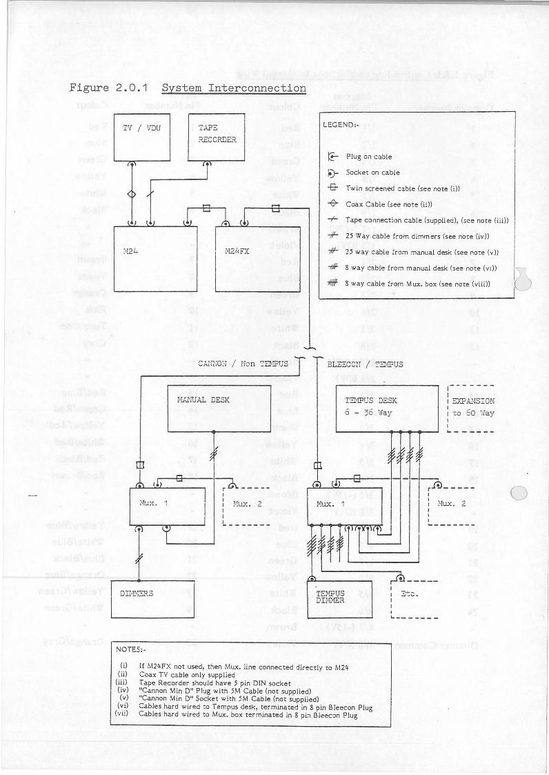
Figure 2.0.1. details the system interconnections. Figure 2.0.2. details the leads used for system interconnection
2.1 Mains Supply:
Connect each unit in turn to the mains supply and check that is is displaying outward signs of basic operation (there is no need to check operation 100% at this point.)
M24 Console M24 Effects Multiplex boxes ACT 6 Mux Permux
- should operate normally - should operate normally - power on LED should illuminate - '-l5V' indicator and channel indicators should light. - No visual indication
Having verified that all of the units are likely to operate, proceed to the next stage.
2.2 Multiplex boxes:
Connect each in turn to the dimmers with the power off. With power applied check that the Multiplex box does not drive any of the dimmers and that there was no noticeable flashup as the box was turned on or off.
If a manual wing is part of the installation, connect it to the Multiplex box and verify that it will drive the dimmers.
On a system of more than 24 channels, connect each Multiplex box to the next and recheck basic operation and for any inter-action between the units.
-4-

2.3 Earth verification:
Connect the Multiplex units to the Dimmers and the Manual Wing.
Connect the M24 Console and M24 Effects Desk together with their jumper cable.
It is now possible to measure the earth current. Connect an Ammeter between the 0 volt pin of the MUX output connector of the M24 Console/Effects Desk and the 0 volt pin of the MUX input connector of the first Multiplex box (figure 2.3.l refers).
Set the Ammeter range progressively more sensitive on both AC and DC to check that there is no current flowing in the earth line with the equipment turned on.
Should any current register, the earthing arrangements must be checked and improved to the point where no measurable current flow is indicated.
2.4 M24 Console & Effects
At this point the output system and manual wing will drive the dimmers and there is no measurable earth current between these units and the M24 Console and Effects.
Connect the two parts of the system together, and make the next set of checks. These checks are to verify that the Console will drive the dimmers, the Effects will receive information from the Console and .the Console will receive and process information from the Effects and/or Manual Wing.
The first stage is to verify that the Console will drive the dimmers.
Set the Manual Master on the Console to zero and the Memory Master to Full. Set each channel, in turn, to full and check that the appropriate dimmer responds. It is not important at this point that the dimmers are accurately adjusted.
Verify that the Effects Desk will load output information from the Console.
Set patterns of channels on the output of the Console and verify that 'Load Output' on the Effects will load the pattern into each master. Check that raising the masters in turn will drive the correct dimmers when the Manual Master on the Console is also raised.
If a Manual Wing is part of the system, check that its output to the dimmers is controlled by the Manual Master on the Console.
As the final stage of this verification procedure, ensure that the Effects will drive the Multiplex boxes, whilst the Console is either turned off or disconnected.
The basic installation should now be complete, with all interconnections made. Cables can now be tidied and any excess length neatly coiled and tied. (Adhesive tape is not recommended for fixing cables as it usually degrades after a few months leaving a sticky mess).
-5-
2.5 Adjustments:
As part of the commissioning procedure, M24 adjustments should be checked and option switches set correctly.
M24 adjustments are set up prior to despatch from Rank Strand, but it is always possible that mechanical vibration in transit has caused movement of the alignment controls.
Adjustments which should be checked are:
1. M24 Multiplex Output Level. 2. Effects Multiplex Output Level. 3. M24 Multiplex Input Level. 4. M24 Wheel 5. Manual Wing.
Access to the adjustments in the M24 system (2 in the Console and 1 in the Effects) is achieved by removing the units' left-hand side panels. This requires both of the rear fixing screws and one of the front fixing screws to be removed completely and the remaining screw slackened to allow the side panel to be hinged upward out of the way. In the Console, RV l is the adjustment closest to the rear of the unit.
2.5. l M24 Multiplex Output Level
The most accurate way of checking this is with an oscilloscope. Set the timebase to 50us per division, and the input attenuator to l V per division. Trigger off a negative going edge below Ov and observe the multiplex output at pin 3 of the output connector, with respect to OV at pin l. Set all channels to full and verify that the measured output level is +5.0V. Adjust RV2 if required.
Figure 2.5. l. shows a multiplexed output waveform.
2.5.2 Effects Multiplex Output Level
Repeat the procedure of section 2.5.1 for the Effects output at pin 3 of the Effects output connector, with the Effects Desk in 'stand alone' mode, i.e. M24 switched off, or disconnected. Adjust RV16 if required.
2.5.3 M24 Multiplex Input Level
a. With an Effects Desk as part of the installation:
Connect the Effects Desk to the M24. Set channels to full on the Effects Desk. Set the Manual Master to full. Adjust RV l on the M24 such that the channels just register full on the VDU.
b. Without an Effects Desk:
Adjust the Manual Wing output (if possible) to produce a +5.0V multiplexed signal at pin 2 of the M24 output connector - with the M24 connected and switched on - for channels at full on the manual wing (see section 2.5.5). Adjust RV 1 such that full level is just registered on the V .D.U. for channels set at full on the Manual Wing.
-6-
2.5.4- Wheel Sensors
The rear cover must be removed from the M24- in order to gain access to the wheel.
Two potentiometers (RVl, RV2) on the wheel P.C.B. control the gain of the opto-couplers which sense wheel movement.
Checking of the adjustment is done using an oscilloscope.
First set the timebase to 2ms per division, and the input attenuators to 100 m V per division. Connect a scope input to TP lA with TP3 as earth. Rotate the wheel very slowly until a minimum voltage is found. Adjust RVl until this voltage is between 200 m V and 300 m V. Rotate the wheel further, when the voltage should rise to approximately 600mV. Repeat the procedure for TP2A, RV2.
Next, connect scope input 1 to TP 1 and scope input 2 to TP2 with TP3 as earth. Set the timebase to 2ms per division and the input attenuators to 2V per division. Set the scope controls to add input 1 and input 2. Move the wheel by hand -the resulting trace should look like that in figure 2.5.4-. If it is not, display each scope input in turn and check for an equal mark-space ratio in the waveform when the wheel is turned. Adjust the corresponding potentiometer until the correct waveform is seen. Then, repeat the 'addition' check.
2.5.5 Manual Wing
The Manual Wing might have its own internal adjustments e.g. SP Mark 2, Threeset, AMC or might have to be internally modified to conform with the output, should the customer require any degree of accuracy in back-up, or if it has to match the characteristics of an M24- Effects. If the desk is fitted with the original Ref. 94-0 Master Amplifier, this may have to be replaed with the Mk 2 version before an accurate adjustment to -lOV maximum can be achieved.
If the Manual Wing is designed to generate an offset on its output voltage to improve the performance of the dimmers, this level will be displayed on the M24- and may cause confusion. If the Wing is an AMC, Rl32 on each of the channel modules should be reduced to 8 K2.
The manual wing output should be adjusted such that a +5.0V multiplex signal is measured at pin 2 of the M24- output connector - with the M24-connected and switched on - for channels at full. Verify also that the manual wing will also drive dimmers to full, when the multiplex boxes are working in 'direct' mode - i.e. no multiplex input.
n.b. It may not be possible to achieve full accuracy of levels seen on the VDU for manual wing inputs. This is because of slight variations in component values within the system. The discrepancies will, however, not seriously affect actual lighting levels in a properly adjusted installation.
2.5.6 Dimmers
After checking the M24- adjustments, the dimmers should be set to give the correct output profile. As the method of adjustment varies with the dimmer type, it is suggested that the relevant dimmer handbook be consulted if there is doubt about the adjustment method.

2.5.7 Option Switches
A set of switches, on the M24 motherboard, is used to set up system parameters. The settings should be altered only if they differ from the customer's requirements.
A summary of switch functions is given below:-
SWl/1-4 SWl/5 SWl/6 SWl/7 SWl/8 SW2/l-3 SW2/4-6
Switch Settings:
Number of channels. Spare Memory Expansion fitted/not fitted. 50Hz/60Hz VDU synchronisation. Debug messages enable. VDU language. Power-Up Mode
SW 1 bits 1 - 4 Number of channels - set as required.
SWl 12 Channels
24
36
48
60
72
84
96
108
120
/1 1
0
1
0
1
0
1
0
1
0
/2 0
1
1
0
0
1
1
0
0
1
/3 0
0
0
1
1
1
1
0
0
0
/4 0
0
0
q
0
0
0
1
1
1
0 = Switch bit open 1 = Switch bit closed.
SWl bit 5 SWl bit6
SWl bit 7
SWl bit 8
Spare - set open. Memory Expansion - set closed if expansion fitted, otherwise set open. 50/60 Hz - set closed if mains frequency is 60 Hz, set open for 50 Hz. Debug messages - set open. (Debug messages appear on the VDU, if enabled, to allow testing of system software. They can appear without any action or hardware fault and may cause alarm to an operator. They should therefore be disabled.)
-8-
(
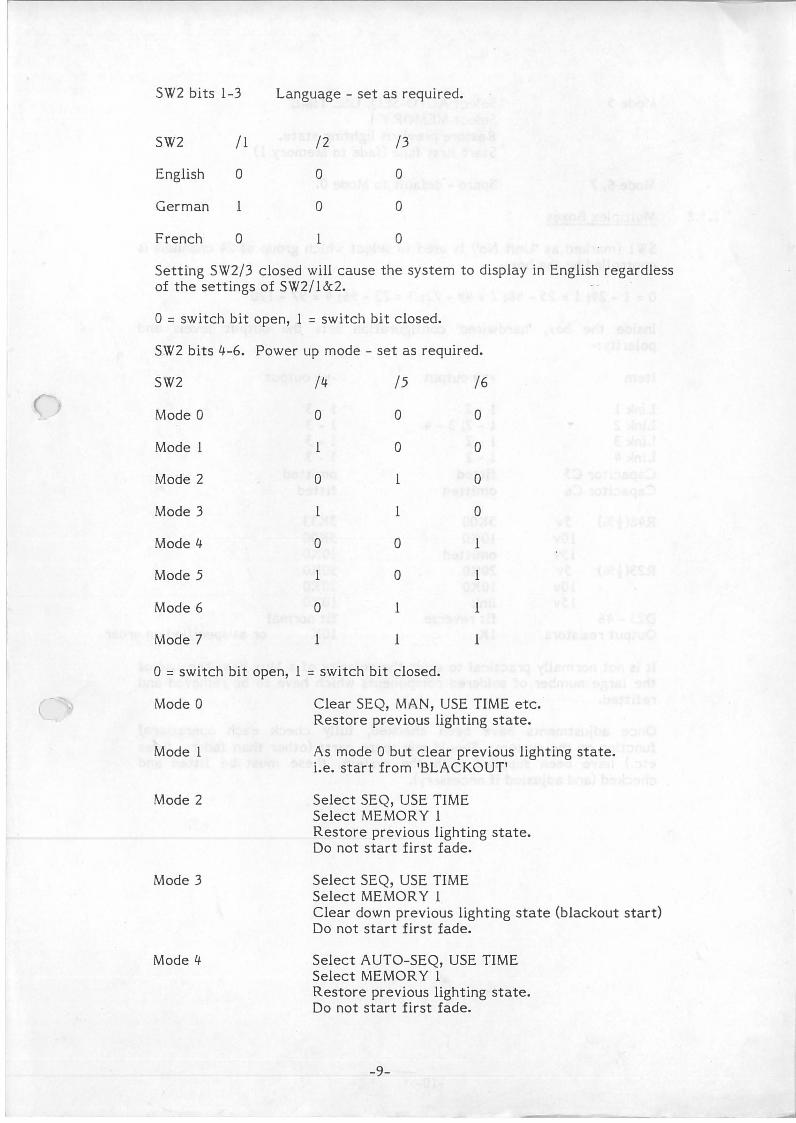
SW2 bits 1-3 Language - set as required.
SW2 /1 /2 /3
English 0 0 0
German l 0 0
French 0 1 0
Setting SW2/3 closed will cause the system to display in English regardless of the settings of SW2/1&2.
0 = switch bit open, l = switch bit closed.
SW2 bits 4--6. Power up mode - set as required.
SW2 /lJ. /5 /6
Mode 0 0 0 0
Model 1 0 0
Mode 2 0 l 0
Mode 3 l l 0
Mode lJ. 0 0 l
Mode 5 1 0 l
Mode 6 0 l l
Mode 7 l l l
0 = switch bit open, l = switch bit closed.
Mode 0
Mode 1
Mode 2
Mode 3
Mode lJ.
Clear SEQ, MAN, USE TIME etc. Restore previous lighting state.
As mode 0 but clear previous lighting state. i.e. start from 'BLACKOUT'
Select SEQ, USE TIME Select MEMORY l Restore previous lighting state. Do not start first fade.
Select SEQ, USE TIME Select MEMORY l Clear down previous lighting state (blackout start) Do not start first fade.
Select AUTO-SEQ, USE TIME Select MEMORY l Restore previous lighting state. Do not start first fade.
-9-
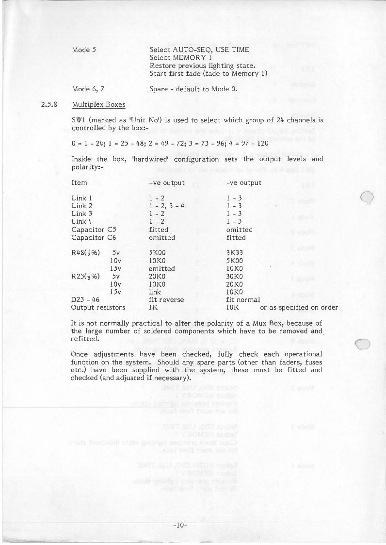
Mode 5
Mode 6, 7
2.5.8 Multiplex Boxes
Select A UTO-SEQ, USE TIME Select MEMORY l Restore previous lighting state. Start first fade (fade to Memory 1)
Spare - default to Mode 0.
SW 1 (marked as 'Unit No') is used to select which group of 24- channels is controlled by the box:-
0 = l - 24-; l = 25 - 4-8; 2 = f./.9 - 72; 3 = 73 - 96; f./. = 97 - 120
Inside the box, 'hardwired' configuration sets the output levels and polarity:-
Item
Link l Link 2 Link 3 Link f./. Capacitor C5 Capacitor C6
Rf./.8(f%) 5v lOv 15v
R23(f%) 5v
023 - f./.6
lOv 15v
Output resistors
+ve output
l - 2 l - 2, 3 - f./. l - 2 l - 2 fitted omitted
5KOO lOKO omitted 20KO lOKO link fit reverse lK
-ve output
l - 3 l - 3 l - 3 l - 3 omitted fitted
3K33 5KOO lOKO 30KO 20KO lOKO fit normal !OK or as specified on order
It is not normally practical to alter the polarity of a Mux Box, because of the large number of soldered components which have to be removed and . refitted.
Once adjustments have been checked, fully check each operational function on the system. Should any spare parts (other than faders, fuses etc.) have been supplied with the system, these must be fitted and checked (and adjusted if necessary).
-10-

3. Handover
The equipment is installed, connected and driving the dimmers. All that remains is to prove this to the customer (or their nominated representative) and obtain a signature that all is correct.
Stage 1 is to prove that each control source will drive the dimmers without inter-action. The control sources are obviously the M24 Console, Effects Desk and/or Manual Wing. At this point it should be possible to demonstrate that certain other facilities are also working and these are:-
i) Back-up operation - if the M24 Console is disconnected,_ .the Effects will drive the dimmers. If the M24 Console and Effects are both disconnected, a Manual Wing will drive the dimmers directly.
ii) Manual Input - all contribution to the lighting state by either the Effects or Manual Wing is controlled by the Manual Master.
iii) Effects - that the M24 Console output can be used to load channels onto the Masters.
Stage 2 is to prove that the M24 Console is working correctly. This is achieved by running the Self Test package to demonstrage that the M24 Console passes all its own tests. (See Guide to Agents Maintenance.) To complete this stage, the M24 operation is demonstrated as the nucleus of an operator training session for the customer/user. This will require a TV or VDU and a cassette recorder to be available.
Stage 3 is to prove that the M24 Effects is workirtg correctly by demonstrating its operation, which again forms the basis of a training session.
Finally, the customer should sign an acceptance that the system is operating to their satisfaction and complete the warranty registration voucher provided with the equipment, returning same to Rank Strand.
-11-
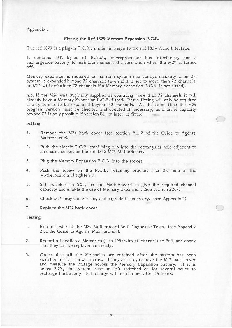
Appendix 1
Fitting the Ref 1879 Memory Expansion P.C.B.
The ref 1879 is a plug-in P.C.B., similar in shape to the ref 1834 Video Interface.
It contains 16K bytes of R.A.M., microprocessor bus interfacing, and a rechargeable battery to maintain memorised information when the M24 is turned off.
Memory expansion is required to maintain system cue storage capacity when the system is expanded beyond 72 channels (even if it is set to more than 72 channels, an M24 will default to 72 channels if a Memory expansion P.C.B. is not fitted).
n.b. If the M24 was originally supplied as operating more than 72 channels it will already have a Memory Expansion P.C.B. fitted. Retro-fitting will only be required if a system is to be expanded beyond 72 channels. At the same time the M24 program version must be checked and updated if necessary, as channel capacity beyond 72 is only possible if version Bl, or later, is fitted
Fitting
1. Remove the M24 back cover (see section A.1.2 of the Guide to Agents' Maintenance).
2. Push the plastic P .C.B. stabilising clip into the rectangular hole adjacent to an unused socket on the ref 1832 M24 Motherboard.
3. Plug the Memory Expansion P.C.B. into the socket.
4. Push the screw on the P .C.B. retaining bracket into the hole in the Motherboard and tighten it.
5. Set switches on SW 1, on the Motherboard to give the required channel capacity and enable the use of Memory Expansion. (See section 2.5.7)
6. Check M24 program version, and upgrade if necessary. (see Appendix 2)
7. Replace the M24 back cover.
Testing
1. Run subtest 6 of the M24 Motherboard Self Diagnostic Tests. (see Appendix 2 of the Guide to Agents' Maintenance).
2. Record all available Memories (1 to 199) with all channels at Full, and check that they can be replayed correctly.
3. Check that all the Memories are retained after the system has been switched off for a few minutes. If they are not, remove the M24 back cover and measure the voltage across the Memory Expansion battery. If it is below 2.2V, the system must be left switched on for several hours to recharge the battery. Full charge will be attained after 14 hours.
-12-
c
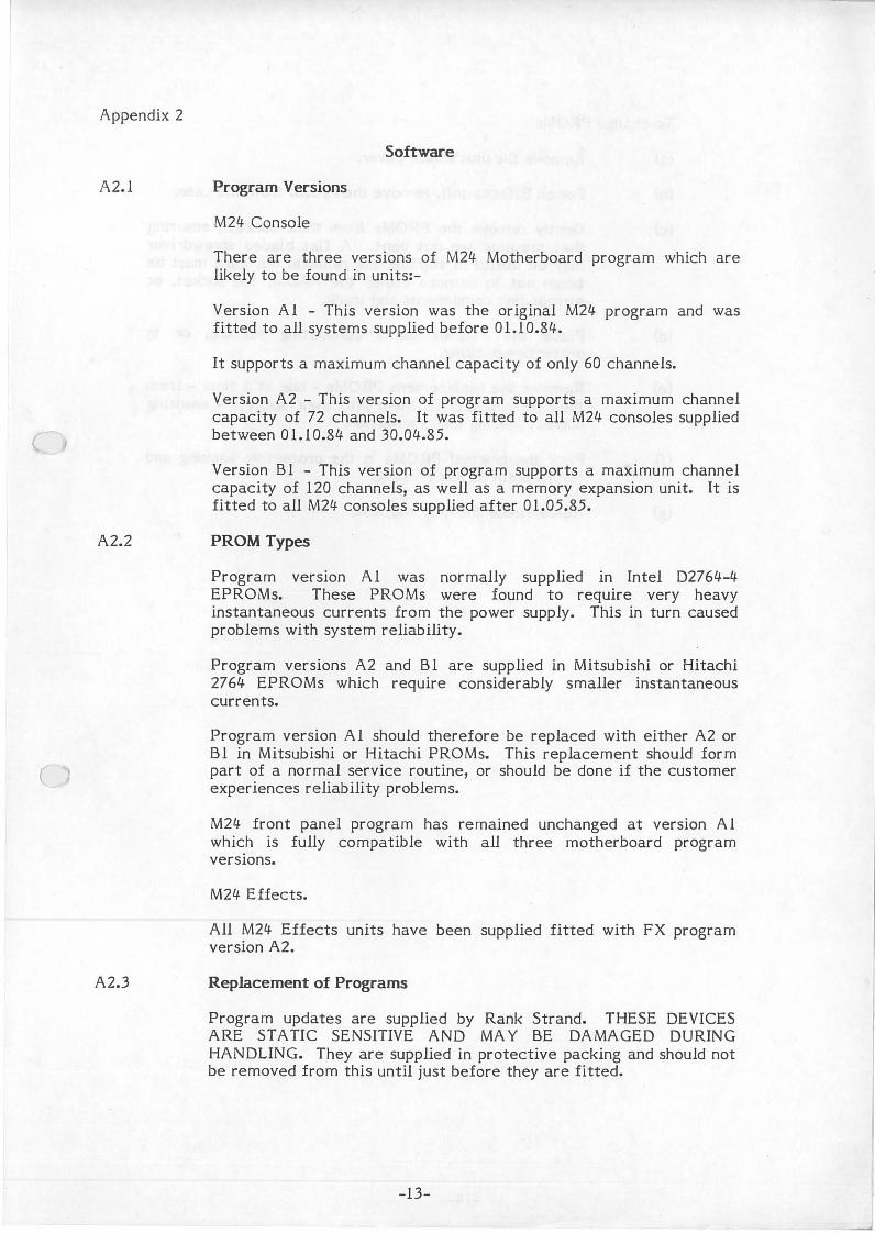
Appendix 2
A2.l
(
A2.2
A2.3
Software
Program Versions
M24 Console
There are three versions of M24 Motherboard program which are likely to be found in units:-
Version Al - This version was the original M24 program and was fitted to all systems supplied before 01.10.84.
It supports a maximum channel capacity of only 60 channels.
Version A2 - This version of program supports a maximum channel capacity of 72 channels. It was fitted to all M24 consoles supplied between 01.10.84 and 30.04.85.
Version BI - This version of program supports a maximum channel capacity of 120 channels, as well as a memory expansion unit. It is fitted to all M24 consoles supplied after 01.05.85.
PROM Types
Program version Al was normally supplied in Intel D2764-4 EPROMs. These PROMs were found to require very heavy instantaneous currents from the power supply. This in turn caused problems with system reliability.
Program versions A2 and BI are supplied in Mitsubishi or Hitachi 2764 EPROMs which require considerably smaller instantaneous currents.
Program version Al should therefore be replaced with either A2 or BI in Mitsubishi or Hitachi PROMs. This replacement should form part of a normal service routine, or should be done if the customer experiences reliability problems.
M24 front panel program has remained unchanged at version Al which is fully compatible with all three motherboard program versions.
M24 Effects.
All M24 Effects units have been supplied fitted with FX program version A2.
Replacement of Programs
Program updates are supplied by Rank Strand. THESE DEVICES ARE STATIC SENSITIVE AND MAY BE DAMAGED DURING HANDLING. They are supplied in protective packing and should not be removed from this until just before they are fitted.
-13-
·1
I
I
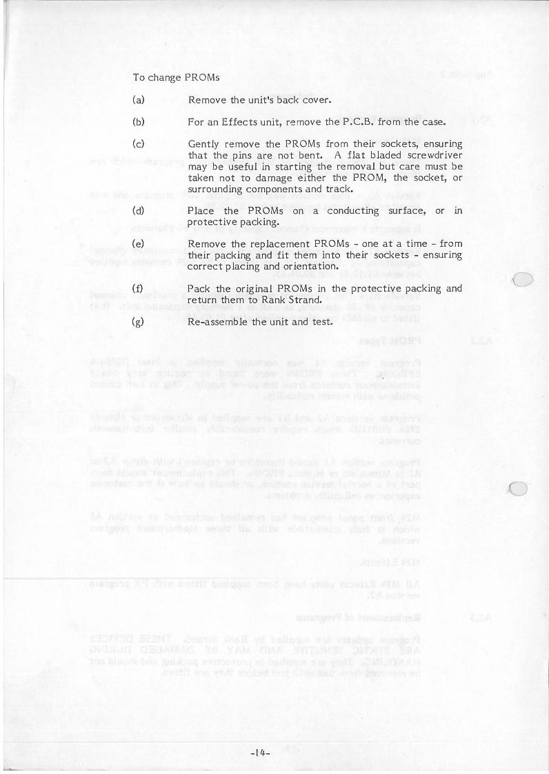
To change PROMs
(a) Remove the unit's back cover.
(b) For an Effects unit, remove the P.C.B. from the case.
(c) Gently remove the PROMs from their sockets, ensuring that the pins are not bent. A flat bladed screwdriver may be useful in starting the removal but care must be taken not to damage either the PROM, the socket, or surrounding components and track.
(d) Place the PROMs on a conducting surface, or in protective packing.
(e) Remove the replacement PROMs - one at a time - from their packing and fit them into their sockets - ensuring correct placing and orientation.
(f) Pack the original PROMs in the protective packing and return them to Rank Strand.
(g) Re-assemble the unit and test.
-14-

r
·Figure 1.2.1 Mains Power Distribution
TV/VDU TA?E
i M24
I
RECORDER
1 M24 FX
MANUAL WING
t % 1 1·TUX. i'IUX. 2 MUX. 3
LEGEND:- .
~ I.E.C. Mains Connector
-r- Mains Lead supplied with T.V. or V.D.U.
-#- Mains Lead supplied 'Nith Casette Recorder or suitable mains adaptor
..,#-- Mains Input or connection to suitable P.S.U. (not supplied) ('Cannon' Min D versions only)
iempus desks wili .-eceive the norm.:;.i -15V from Tempus racks when their conneC:tion is made using a 'Bleecon' Multiplex box.
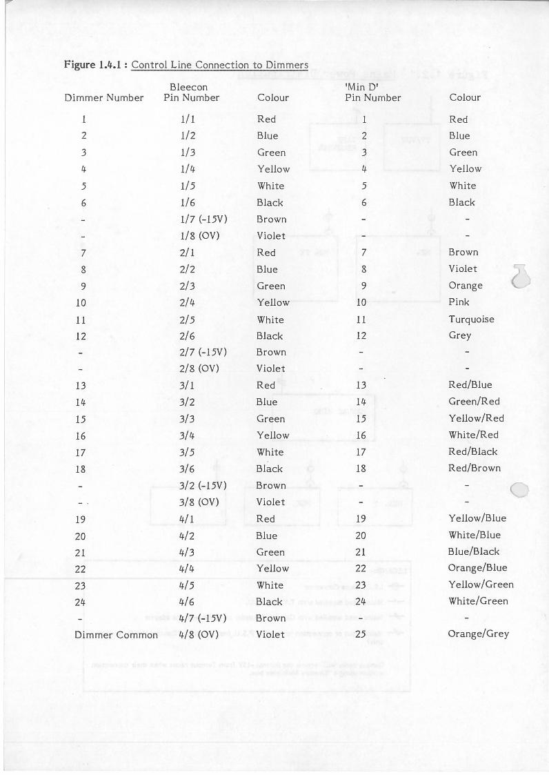
Figure 1.4.1 : Control Line Connection to Dimmers
Bleecon 'Min D' Dimmer Number Pin Number Colour Pin Number Colour
l 1/ l Red l Red
2 1/2 Blue 2 Blue
3 1/3 Green 3 Green
4 1/4 Yellow 4 Yellow
5 1/5 White 5 White
6 1/6 Black 6 Black
1/7 (-15V) Brown
1/8 (OV) Violet
7 2/1 Red 7 Brown
8 2/2 Blue 8 Violet
9 2/3 Green 9 Orange
10 2/4 Yellow 10 Pink
11 2/5 White 11 Turquoise
12 2/6 Black 12 Grey
2/7 (-15V) Brown
2/8 (OV) Violet
13 3/1 Red 13 Red/Blue
14 3/2 Blue 14 Green/Red
15 3/3 Green 15 Yellow/Red
16 3/4 Yellow 16 White/Red
17 3/5 White 17 Red/Black
18 3/6 Black 18 Red/Brown
3/2 (-15V) Brown c 3/8 (OV) Violet
19 4/1 Red 19 Yell ow /Blue
20 4/2 Blue 20 White/Blue
21 4/3 Green 21 Blue/Black
22 4/4 Yellow 22 Orange/Blue
23 4/5 White 23 Yellow/Green
24 4/6 Black 24 White/Green
4/7 (-15V) Brown
Dimmer Common 4/8 (OV) Violet 25 Orange/Grey
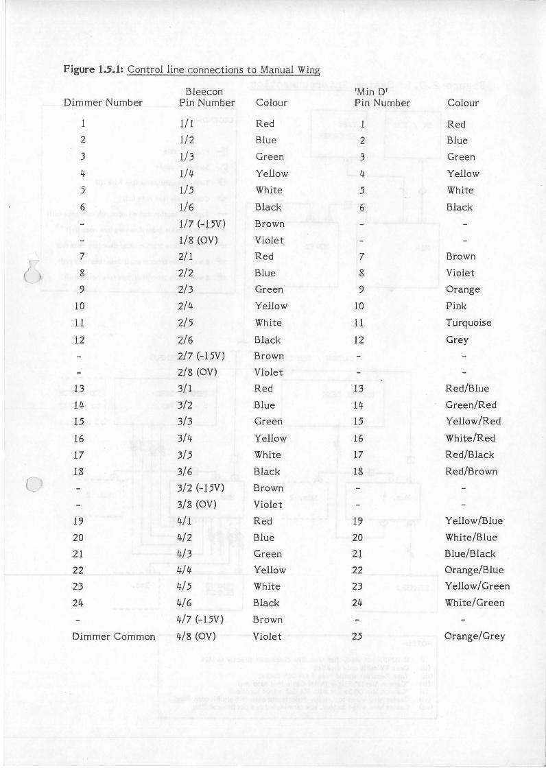
Figure 15.1: Control line connections to Manual Wing
Bleecon 'Min D' Dimmer Number Pin Number Colour Pin Number Colour
l 1/ l Red l Red
2 1/2 Blue 2 Blue
3 1/3 Green 3 Green
4 1/4 Yellow 4 Yellow
5 1/5 White 5 White
6 1/6 Black 6 Black
1/7 (-15V) Brown
1/8 (OV) Violet
7 2/1 Red 7 Brown
8 . 2/2 Blue 8 Violet
9 2/3 Green 9 Orange
10 2/4 Yellow 10 Pink
11 2/5 White 11 Turquoise
12 2/6 Black 12 Grey
2/7 (-15V) Brown
2/8 (OV) Violet
13 3/1 Red 13 Red/Blue
14 3/2 Blue 14 Green/Red
15 3/3 Green 15 Yellow/Red
16 3/4 Yellow 16 White/Red
17 3/5 White 17 Red/Black
18 3/6 Black 18 Red/Brown
3/2 (-15V) Brown
3/8 (OV) Violet
19 4/ 1 Red 19 Yellow /Blue
20 4/2 Blue 20 White/Blue
21 4/3 Green 21 Blue/Black
22 4/4 Yellow 22 Orange/Blue
23 4/5 White 23 Yellow/Green
24 4/6 Black 24 White/Green
4/7 (-15V) Brown
Dimmer Common 4/8 (OV) Violet 25 Orange/Grey
.Figure 2.0.1
1'124
Mux.
DII-lYi:SRS
NOTES:-
System Interconnection
T.APE
RECORDEH
(f\
M24FX
CANr;QI.I / Non TEMPUS
MANUAL DESK
0 ~-----
1
: Mux. 2 I I
L-------
LEGEND:-
~ Plug on cable
& Socket on cable
-8- Twin screened cable (see note (i))
v Coax Cable (see note (ii))
+ Tape connection cable (supplied), (see note (iii))
+ 25 Way cable from dimmers (see note (iv))
+ 25 way cable from manual desk (see note (v))
-ii#- 8 way cable from manual desk (see note (v i))
i'!# 8 way cable from Mux. box (see note (viii))
BLZECON / '.!.'EMPUS
TEMPUS DESK 6 - 36 Way
1 -------I 1 EXPANSION I 1 t o 60 i;fay I I -------
_ __.9..._ ___ ,l-l- - ---.
r..{!}_ - -- -I
Mux.
TEMP US DII1r'IER
: Mux. 2
Etc.
I
"--------
(i) If M24FX not used, then Mux. line connected directlv to M21t (ii) Coax TV cable only supplied ·
(iii) Tape Recorder should have 5 pin DIN socket (iv) "Cannon ~!in D" Pl•Jg with jM Cable (not supplied) (v) "Cannon Min D" Socket with 5M Cable (not supplied)
(vi) Cables hard wired to Tempus desk, terminated in 8 pin Bleecon Plug (vi!) Cables hard wired to Mux. box terminated in 8 pin.Bleecon Plug
Jo:--
)
0
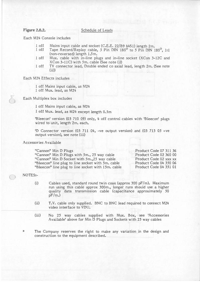
Figure 2.0.2. Schedule of Leads
Each M2l/. ~onsole includes
1 off Mains input cable and socket (C.E.E. 22/B9 l/.l/.S 1) length 2m. l off Tape Record/Replay cable, 5 Pin DIN 180° to 5 Pin DIN 180°, 1:1
(non-reversed) length 1.5 m. 1 off Mux. cable with in-line plugs and in-line socket (XCon 3-12C and
XCon 3-11 C) with 5m. cable (See note (i)) 1 off TV connector lead, Double ended co axial lead, length 2m. (See note
(ii))
Each M2l/. Effects includes
1 off Mains input cable, as M2l/. 1 off Mux. lead, as M2l/.
Each Multiplex box includes
1 off Mains input cable, as M2l/.
1 off Mux. lead, as M2l/. except length 0.5m
'Bleecon' version (03 710 09) only, l/. off control cables with 'Bleecon' plugs wired to unit, length 2m. each.
'D Connector version (03 711 04-, -ve output version) and (03 713 05 +ve output version), see note (iii)
Accessories Available
"Cannon" Min D Plugs "Cannon" Min D Plugs with 5m., 25 way cable "Cannon" Min D Socket with 5m.,25 way cable "Bleecon" line plug to line socket with 5m. cable "Bleecon" line plug to line socket with l5m. cable
NOTES:-
Product Code 07 311 36 Product Code 02 360 00 Product Code 02 xxx xx Product Code 04- 350 06 Product Code 04- 351 01
(i) Cables used, standard round twin coax (approx 300 pF/m). Maximum run using this cable approx 300m., longer runs should use a higher quality data transmission cable (capacitance approximately 50 pF/m.)
(ii) T.V. cable only supplied. BNC to BNC lead required to connect M2l/. video interface to VDU.
(iii) No 25 way cables supplied with Mux. Box, see 'Accessories Available' above for Min D Plugs and Sockets with 25 way cables
* The Company reserves the right to make any variation in the design and construction to the equipment described.
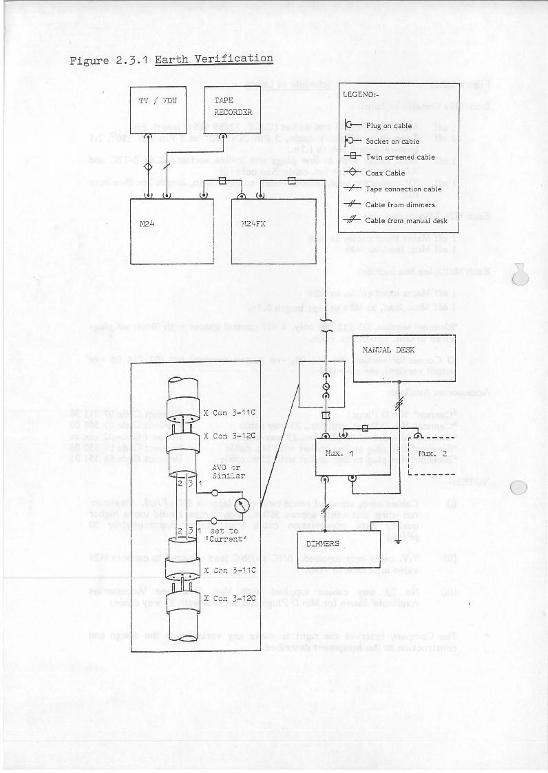
Figure 2.3.1 Earth Verification
TV / VDU
M24
1
TAPE RECORDER
L'~2l..FX
Con 3- 11 C
X Co::i 3- 12C
AVO or Similar
.set to 1 Current 1
X Con 3- 12C
LEGEND:-
IG-- Plug on cable
r:>- Socket on cable
-8- Twin screened cable
+Coax Cable
-f- Tape connection cable
-#- Cable from dimrr.ers
-;ffL- Cable from manual desk
1 ,
MA1'JUAL DESK
0
Mux. 1 l?-----
1 Mux. 2 I I
L-------
DI1'!!1ERS
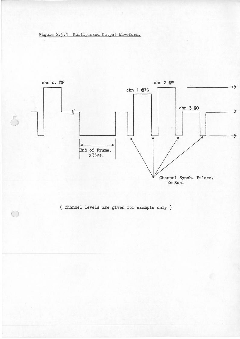
Figure 2.5.1 Multiplexed Output Waveform.
chn n. @F chn 2 @F
~ .
d of Frame. >35us.
chn 1 @75
chn 3 00
Synch. Pulses. -::::::: Bus.
( Channel levels are given for example only )
-5'