Embed Size (px)
Citation preview
STRAIN GAUGES
By: Pinank ShahDate : 03/22/2006

Pinank Shah
Overview of Topics
What is Strain? What is Strain Gauge? Operation of Strain Gauge Grid Patterns Strain Gauge Installation Wheatstone bridge Instrumentation Amplifier Embedded system and Strain Gauge Strain Measurement System Applications of a Strain Gauge

Pinank Shah
What is Strain ? Strain is the amount of deformation of a body due to an applied
force. More specifically, strain (e) is defined as the fractional change in length.
Strain can be positive (tensile) or negative (compressive). Although dimensionless, strain is sometimes expressed in units such as in./in. or mm/mm.
In practice, the magnitude of measured strain is very small. Therefore, strain is often expressed as microstrain (me), which is e x 10-6.
Pinank Shah
What is a Strain Gauge ?
Strain Gauge is a device used to measure deformation (strain) of an object.
Strain gauges have been developed for the accurate measurement of strain
Fundamentally, all strain gauges are designed to convert mechanical motion into an electronic signal.
Pinank Shah
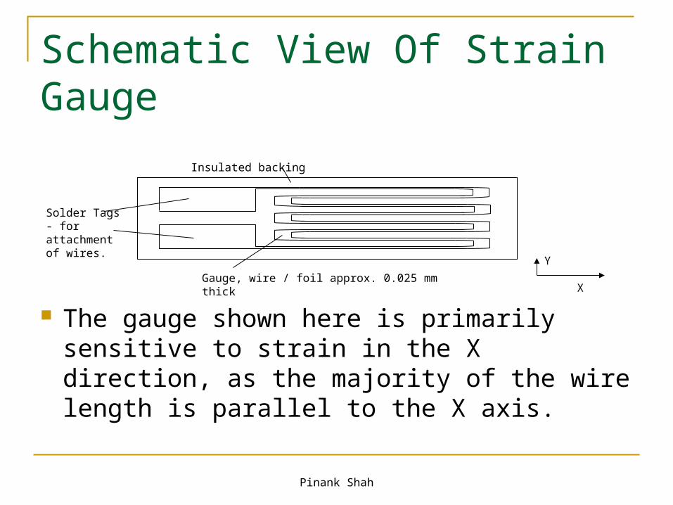
Schematic View Of Strain Gauge
The gauge shown here is primarily sensitive to strain in the X direction, as the majority of the wire length is parallel to the X axis.
Solder Tags - for attachment of wires.
Insulated backing
Gauge, wire / foil approx. 0.025 mm thickX
Y
Pinank Shah
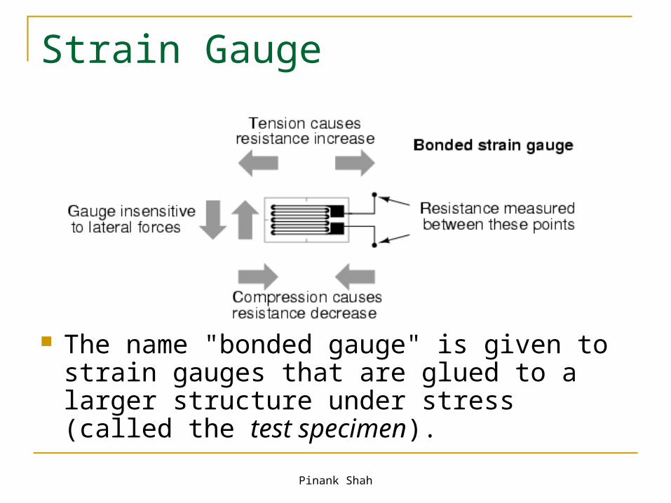
Strain Gauge
The name "bonded gauge" is given to strain gauges that are glued to a larger structure under stress (called the test specimen).
Pinank Shah
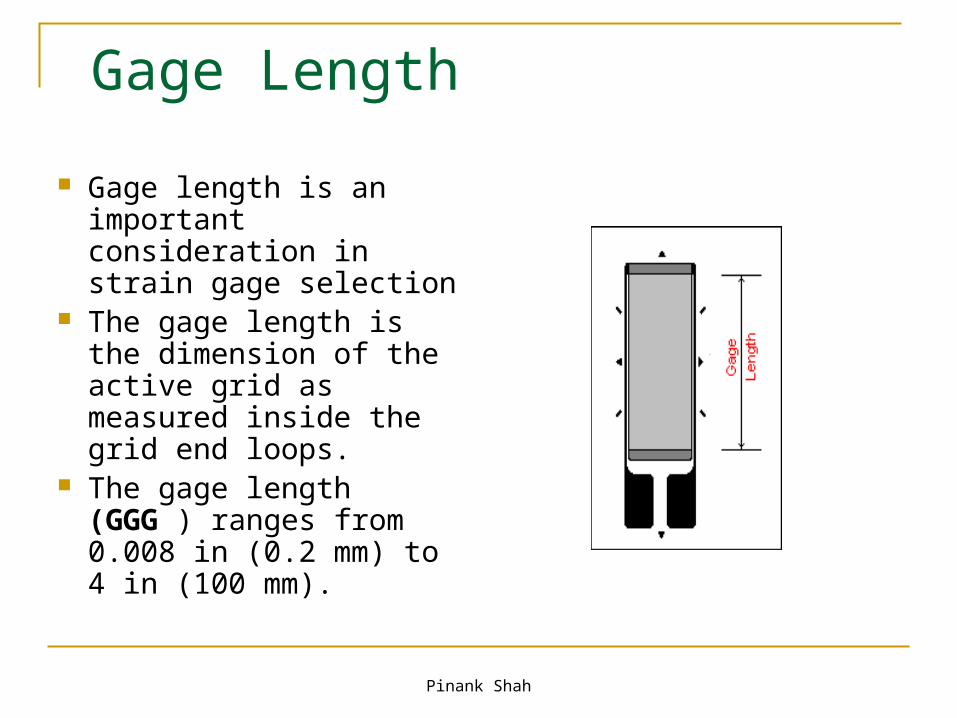
Gage Length
Gage length is an important consideration in strain gage selection
The gage length is the dimension of the active grid as measured inside the grid end loops.
The gage length (GGG ) ranges from 0.008 in (0.2 mm) to 4 in (100 mm).

Pinank Shah
Strain Gauge Operation
This schematic shows how the strain gauge resistance varies with strain (deformation).
On applying a force a change in resistance takes place.
Tension causes resistance increase.
Compression causes resistance decrease.
+-
Pinank Shah
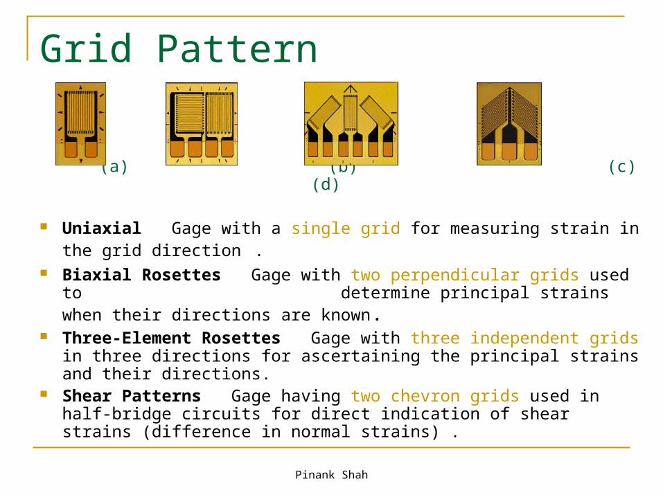
Grid Pattern
(a) (b) (c) (d)
Uniaxial Gage with a single grid for measuring strain in the grid direction .
Biaxial Rosettes Gage with two perpendicular grids used to determine principal strains when their directions are known.
Three-Element Rosettes Gage with three independent grids in three directions for ascertaining the principal strains and their directions.
Shear Patterns Gage having two chevron grids used in half-bridge circuits for direct indication of shear strains (difference in normal strains) .

Pinank Shah
Strain Gauge Installation
The Strain Gauge is bonded to the specimen under test, only after the following: cleaning the surface using a degreaser cleaning it again with a conditioner solution (mild
acid that accelerates the cleaning process) neutralizing by applying a base (neutralizes any
chemical reaction introduced by the Conditioner) finally bonding it with a super glue.
The Strain Gauge has 2 leads which exhibit variation in resistance when strain is applied.

Pinank Shah
The bonded metallic strain gauge The metallic strain gauge consists of a
very fine wire or metallic foil arranged in a grid pattern.
The grid pattern maximizes the amount of metallic wire or foil subject to strain in the parallel direction.
The grid is bonded to a thin backing, called the carrier, which is attached directly to the test specimen.
The strain experienced by the test specimen is transferred directly to the strain gauge, which responds with a linear change in electrical resistance.
Gauge factor is defined as:
Pinank Shah
Measuring Circuits
In order to measure strain with a bonded resistance strain gauge, it must be connected to an electric circuit that is capable of measuring the minute changes in resistance corresponding to strain
Strain gauge is connected in a Wheatstone bridge circuit
A strain gauge bridge circuit indicates measured strain by the degree of imbalance
It provides an accurate measurement of that imbalance

Pinank Shah
Wheatstone Bridge In Figure, if R1, R2, R3, and
Strain gauge are equal, and a voltage, VIN, is applied between points A and C, then the output between points B and D will show no potential difference.
However, if R4 is changed to some value which does not equal R1, R2, and R3, the bridge will become unbalanced and a voltage will exist at the output terminals.
The variable strain sensor has resistance Rg, while the other arms are fixed value resistors.

Pinank Shah
Wheatstone Bridge
The sensor, however, can occupy one, two, or four arms of the bridge, depending on the application.
The total strain, or output voltage of the circuit (Vout) is equivalent to the difference between the voltage drop across R1 and R4, or Rg.
It is given by Vout = Vcd – Vcb

Pinank Shah
Wheatstone Bridge Working The bridge is considered balanced when R1/R2 =
Rg/R3 and, therefore, VOUT equals zero. Any small change in the resistance of the sensing
grid will throw the bridge out of balance, making it suitable for the detection of strain.
A small change in Rg will result in an output voltage from the bridge.
If the gage factor is GF, the strain measurement is related to the change in Rg as follows:
Pinank Shah
Problem - Low Level Output
The output of a strain gauge circuit is a very low-level voltage signal
The low level of the signal makes it particularly susceptible to unwanted noise from other electrical devices.
Capacitive coupling caused by the lead wires' running too close to AC power cables or ground currents are potential error sources in strain measurement.
Other error sources may include magnetically induced voltages when the lead wires pass through variable magnetic fields, parasitic (unwanted) contact resistances of lead wires, insulation failure, and thermocouple effects at the junction of dissimilar metals.
The sum of such interferences can result in significant signal degradation.

Pinank Shah
Solution
Shielding: Most electric interference and noise problems can be solved by shielding.
A shield around the measurement lead wires will intercept interferences and may also reduce any errors caused by insulation degradation.
Shielding also will guard the measurement from capacitive coupling.
If the measurement leads are routed near electromagnetic interference sources such as transformers, twisting the leads will minimize signal degradation due to magnetic induction.
By twisting the wire, the flux-induced current is inverted and the areas that the flux crosses cancel out.
For industrial process applications, twisted and shielded lead wires are used almost without exception.

Pinank Shah
Instrumentation Amplifier The variation in voltage at the output of the bridge is in
the range of millivolts. It needs to be amplified in order to
calculate precise value of strain.
Vout
+V1
+V2
10K
500 ohms
10K
10K
10 K 10K
10K
-Vcc
+vcc
+Vcc
+Vcc
-Vcc
-Vcc
2
3
6
6
3
2
2
3
+
+
-
-
+
-
6
InstrumentationAmplifier
Pinank Shah
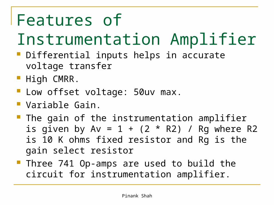
Features of Instrumentation Amplifier Differential inputs helps in accurate voltage transfer High CMRR. Low offset voltage: 50uv max. Variable Gain. The gain of the instrumentation amplifier is given by
Av = 1 + (2 * R2) / Rg where R2 is 10 K ohms fixed resistor and Rg is the gain select resistor
Three 741 Op-amps are used to build the circuit for instrumentation amplifier.

Pinank Shah
Instrumentation Amplifier and Microcontroller Integration The output of the
instrumentation amplifier is connected to the M16C/62P microcontroller.
The ADC, converts the o/p into digital value and the voltage read in is displayed on the LCD display available on M16CSKP board.
A_D converter input port no. 10_3 is used
The A_D converter is configured to read in the analog value after every 1 second and is set to convert at a resolution of 10 bits for better precision.
Pinank Shah
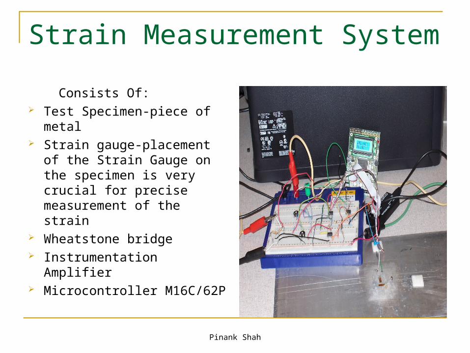
Strain Measurement System
Consists Of: Test Specimen-piece of
metal Strain gauge-placement of
the Strain Gauge on the specimen is very crucial for precise measurement of the strain
Wheatstone bridge Instrumentation Amplifier Microcontroller M16C/62P
Pinank Shah
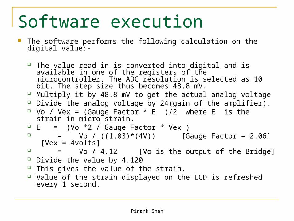
Software execution The software performs the following calculation on the digital value:-
The value read in is converted into digital and is available in one of the registers of the microcontroller. The ADC resolution is selected as 10 bit. The step size thus becomes 48.8 mV.
Multiply it by 48.8 mV to get the actual analog voltage Divide the analog voltage by 24(gain of the amplifier). Vo / Vex = (Gauge Factor * E )/2 where E is the strain in micro
strain. E = (Vo *2 / Gauge Factor * Vex ) = Vo / ((1.03)*(4V)) [Gauge Factor = 2.06] [Vex = 4volts] = Vo / 4.12 [Vo is the output of the Bridge] Divide the value by 4.120 This gives the value of the strain. Value of the strain displayed on the LCD is refreshed every 1
second.
Pinank Shah
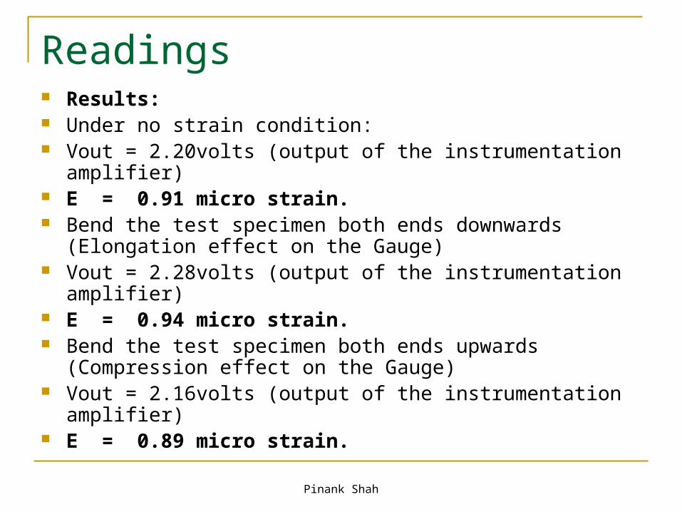
Readings Results: Under no strain condition: Vout = 2.20volts (output of the instrumentation amplifier) E = 0.91 micro strain. Bend the test specimen both ends downwards (Elongation effect
on the Gauge) Vout = 2.28volts (output of the instrumentation amplifier) E = 0.94 micro strain. Bend the test specimen both ends upwards (Compression effect
on the Gauge) Vout = 2.16volts (output of the instrumentation amplifier) E = 0.89 micro strain.
Pinank Shah
Features Of Strain Measurement System This system is very compatible and is cost
effective. The microcontroller used has many other
features like UART interface which can be utilized to transfer the strain readings to a PC.
Upcoming Project: - A multi strain measurement system (SMS) - Making SMS wireless
Pinank Shah
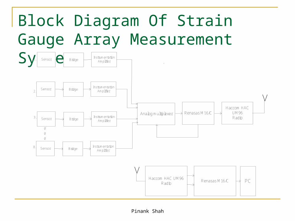
Block Diagram Of Strain Gauge Array Measurement System
v 2..
3..
1.
8.
0
0
0
Sensor BridgeInstrumentation
Amplifier
Analog multiplexer Renasas M16/CHaccom HAC
UM96Radio
Sensor BridgeInstrumentation
Amplifier
Sensor BridgeInstrumentation
Amplifier
Sensor BridgeInstrumentation
Amplifier
vHaccom HAC UM96
RadioRenasas M16/C PC
vv
vv
Pinank Shah
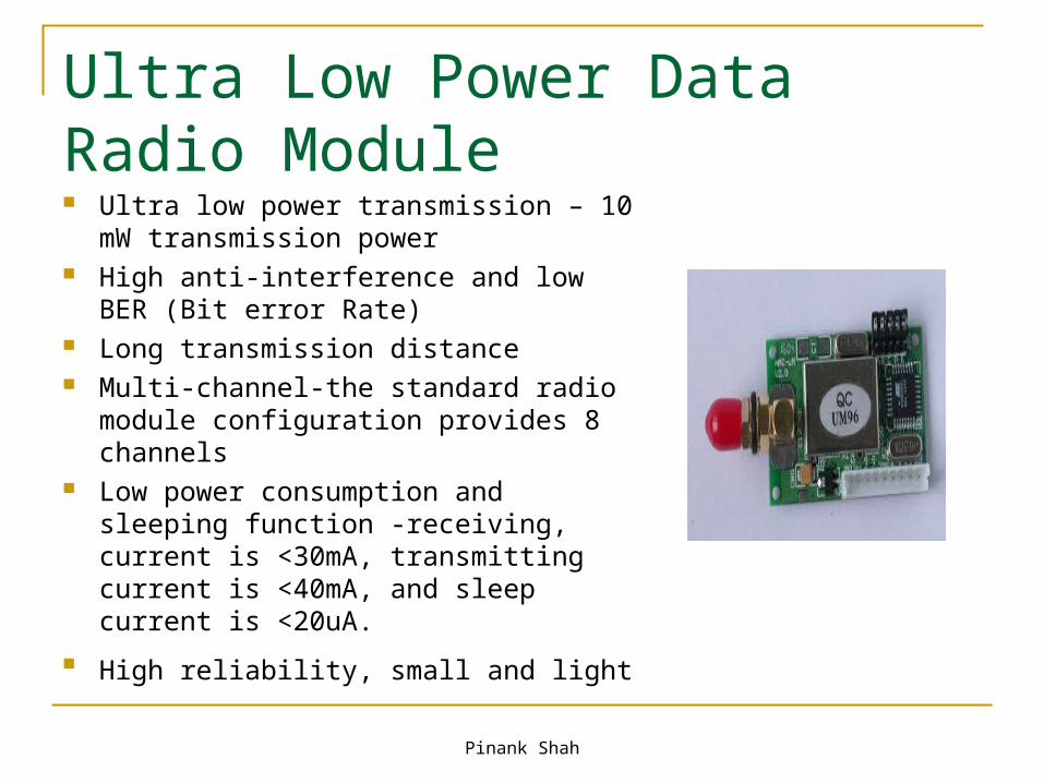
Ultra Low Power Data Radio Module Ultra low power transmission – 10 mW
transmission power High anti-interference and low BER (Bit
error Rate) Long transmission distance Multi-channel-the standard radio module
configuration provides 8 channels Low power consumption and sleeping
function -receiving, current is <30mA, transmitting current is <40mA, and sleep current is <20uA.
High reliability, small and light
Pinank Shah
Strain Gauge Array Measurement System The advanced strain measurement system
accumulates the data from all the widespread gauges, processes the collected data, enables wireless transmission of collected information to the remote Data Acquisition System.
With the combination of low power microprocessors, flexible software operating modes this system is optimized for very low power operation, while permitting high speed data logging and wireless communication capabilities.

Pinank Shah
Applications of Strain gauge
In load cells for weighbridges, scales, vehicles and in medical and educational applications.
For monitoring structures such as bridges and buildings.
In research and development applications, including automotive, aerospace, medical, process, oil and gas, and power generation.
Virtually every other sector of industry.
Pinank Shah
References
http://zone.ni.com/ http://www.omega.com/ http://www.vishay.com/ http://www.allaboutcircuits.com/ http://www.strain-gauges.com/

Pinank Shah

Pinank Shah
QUESTIONS…..


![strain gauge best practices [Read-Only]Best Practices for Strain Gauge Correlation Joe Spadola ... gauge to correlate an FE model’s results with measured strain data • Does the](https://img.pdfslide.us/doc/110x75/5e72c3453109d856950eff76/strain-gauge-best-practices-read-only-best-practices-for-strain-gauge-correlation.jpg)