Embed Size (px)
Citation preview
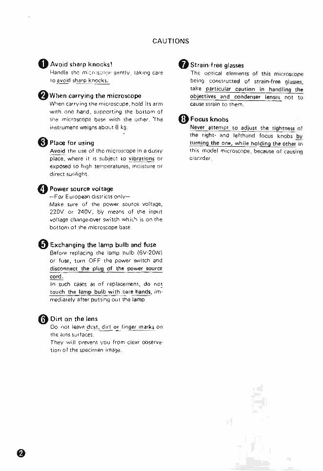
CAUTIONS
o Avoid sharp knocks ~ Stra in -free glasses Handle the microscope gentl y taking care
t o avoid sharp knocks
f)When carry ing the microscope When carry ing the microscope hold i ts arm
with one hand supporting the botto m of
th e microscope bJse w i th the uther The
instrumen t weighs about 8 kg
8 Place for using Avoid the use of the m icruscope in a dusty
place where it IS subjec t to ~brat i ons or exposed to high temperatures rY10 lstu re or direct sun light
oPower source voltage -For European di stricts only -Make sure of the power source voltage nov or 240V bY means of the input
voltage change-over switch wh ich is on the
bottom of the microscope base
oExchanging the lamp bulb and fuse Before replacing he lamp bulb (6V-20WI or fuse turn OF F the power SVIIitch and disconnect the p lug of the power source
cord In such cases as of rep lacement do not touch the lamp bulb w ith bare hands imshy
mediately after putti ng out the lamp
o Dirt on the lens Do not leave dust dirt or finger marks on
the lens surfaces They will p revent you from clcar observashy
tion o f the specimen image
Th e optical elements of this m icroscope
being constructed o f stra in-f ree glasse~
la ke particular caution in hand ling the
objectives and condenser lenses not tu cause st rain t o t hem
laquo) Focus knobs Never attempt to adjust the l ightness o f the r ight- and le tthand focus knobs by
tu rn ing the one while holding the o ther in
this model microscope because of causing disorder
CARE AND MAINTENANCE
o Cleaning the lenses To clean the lens surfaces remove dust using a soft brush o r gauze Only for removing f inger marks or grease should
soft cotton cloth lens tissue or gauze lightly moistened with absolute alcohol
(methano l or ethanol) be used For cleaning the objectives and immersion oil use only xylene Observe su ff icient caut ion in handling alcoho l and xylene
f) Cleaning the painted surfaces Avoid the use of any organic solvent (for example thinner ether alcohol xylene etc) fo r cleaning the pa inted surfaces and
plastic parts o f the instrument
)Never attempt to dismantle Never attempt to dismantle the instrument so as to avoid the possibility of impairing the opera t ional efficiency and accuracy
O When not in use When not in use cover the instrument with the accessory viny l cover and store it in a
placeJree from moisture and fungus It is especially recom mended that the objectives and eyepieces be kept in an airtight con tainer con tai ning desiccant
o Periodical checking To maintain the performance of the instru shyment we recommend to check the instru shyments periodicall y (For details of this check contact our agency )
CONTENTS
I NOMENCLATURE
II ASSEMBLY
III PREPARATION 1 Interpupillary Distance Adjustment
2 Diopter Adjustment 3 Optical Path Change-over in the
Trinocular Eyepiece Tube TP
4 Centering the Objectives 5 Centering the Condenser Lens 6 Orientation of the Dia-polarizer
IV MICROSCOPY 1 Operating Procedure 2 Manipulation of Each Elemen t
1) Focusi ng
2) Co ndenser aperture diaphragm 3) Field diaphragm 4) Circular graduated stage
5) Objectives 6) Eyep ieces 7) Achromat strain-free condenser 8) Bertrand lens
9) 14 A amp tint plate 10) Dia-polarizer and analyzer
11) Filters 12) Illumination system
V PHOTOMICROGRAPHY
VI ACCESSORIES 1 5enarmont Compensator 2 Quartz Wedge 3 Monocular Eyepiece Tu be AP 4 Universal epi-illuminator
5 Attachable Mechanical Stage Type E 4f)
VII TROUBLE SHOOTING TABLE W REFERENCE ) ELECTRIC SPECIFICATIONS )
(j) (j) o o ~ ~ Ql Ql Ql Ql I) I)
~ ~ ~
~
~ ~ ~ 4l)4ll
I NOMENCLATURE
Binocular eyepiece tube BP
Interpupillary distance scale Eyepiece tube clamp screw- ---
Diopter ring
Centering nosepiece
----~ CF Achro~ma~t~P~o~~~~_ ____ (strain~free )
Circular stage
Circular graduated stage clamp screw
Vernier
Achromat strain-fr ee conde nser
CF
Bertrand lens I
Analyzer inout knob
Intermediate tube clamp screw
Coarse knob
Fine focus knob
Orientation plate
Filter receptacle
Fig 1
Analvzer rota t Ion ring
In termed iate tube P
Analyzer clamp screw
Compensator slot
14 amp tint
Condenser focus knob
Nosepiece centering screw
clip
Torque adjustment ring
Lamp socket
Field diaphragm control ring
V-POL stand
~ rotation clamp screw
Condenser centering screw
Condenser aperture control ring
Condenser clamp sere
Field lens
Brightness control dial
(including power switch)
Fig 2
o
II ASSEMBLY
bull To assemble the microscope follow the procedure in the order given
Bottom of the Base CF eyepiece ~ ~=-n-se~~t~th-e-ey-e- ie-c-e-C=-=FWCC--=O-p X-C-M--~reg into the right-hand sleeve fitting
sta
the pin of the eyepiece in the right-h and no tch o f the sleeve Into the left-hand sleeve insert IheCFW l Ox 1111 I G
I bull - ~~
reg~1~4~A~amp~t_intpl~at~e____~____~ Remove the screw by the side o f the 14 A plate o f the 14 A amp tint plate and insert it into the co mshypensator slo t of the in termediate tube P facing the posit ioningInput voltage change-over groove t oward the operator side
switch Reatwch the removed screw (For European districts only)
sure power source ~C~ ~ ~at~p ~____________~F Ac h~r~om ~ ~O~b~je=-C~t~iv~e __________~vol (age 220V or 240V by means reg ----shy
of the input vUl wge change-over Mount the objectives on the nose-switch on the bottorn of the piece in such posi tions that their roicroscopp bnse mvgnifying power increases as the
nosepiece is revolved clockwise
Bottom of the Bas8 I -=Scp-=-~ n~ _ _ ~-eci me~ c lip_ ___ ~
Place the clip on the stage using ho les on t he swgc surfClce Stage clamp sclew-----I1JIl
~1i~i~i~~~~~m~~~t~e~~t~t~he~St~~g~e~o~n--1 the circu lar d ovetail o f the subshystClge Clamp the sc rew
microscope mnn ipulJte th rllt shyjng screw at on~ foot on the bottom o f the microscope base
2 Achromat condense nsen 10 con shy
denscr facin g Ihe apertu re number p late toward the operator Fasten the clamp screw on the left side of the carrier
Aperture number pl _ _ ____J
-=Dia-p -Iar--- r -- - taJ --- shy-=-c---o iz---e --------- -Gmfl23~After centering th e objec shyt ives and condenser insert the dia-polari7er in lO the bottom of the condenser
(J) Eyepiece tube
Attach the eyepiece [Ube on the intermediate lUbe p fitting the notch o f the circular dovetai l on the end of the clamp screw Fasten the clamp screw
Eyepiece tube clamp screw
regIntermediate tube P
1 Atlach the intermediate tube P un the arm o f t he V-POL stand fi lling the notch of the c ircular dovetail on the end at [he clamp screw Fasten the clamp screw
ntermediate tube clamp screw
Power source
Halogen lamp bulb (6V-20W)
In se rt the lamp bulb with its pins into the accePting holes in the socket Note Dont touch the bu lb surshy
fa ce direct ly with the finshyger
reg Lamp socket - Insert socket into the recep shy
tacle on the rear of the baSElL - lte-___ _FiO r Place the filler on the fie ld tens q 45
Fig 3
III PREPARATION
1 Interpupillary Distance Adjustment
Place a spec imen on the stage and focus on the specimen
A s shown in Fig 4 ad just the interpupill ary
d istance so tha t both the righ t and le ft viewshyfields become one
Fig 4
2 Diopter Adjustment
Ro tate the d iopter ring on the eyepiece CFW
l OX e M until the cross lines are seen clear (Fig 5 )
Diopter ring --
Fig 5
(For b inocular observa t ion) 1) Mount the specimen on the stage Swing
the objective l OX into position and bring the specimen image into focus looking into
the right-hand eyepiece 2 ) Without manipulating the coarse-and-fine
focus knob turn the diopter rtng on the left-hand ey epiece to focus on the specimiddot
men
3 Optical Path Change-over in the Trinocular Eyepiece Tube TP
(Fig 6)
Vert ical photo 1 tube 86
Observation Observat ion ~~~Jl~ tu be 100 tu be 14-OPtical pltlIh shy
change-o ver knob
Fig6
I Since Ihe CF eyep ieces are of high eyemiddot
po int ty pe i t is no t neCe55ary for the user
putting on his spectacles to remove them Only fo ld down the eyeguard rubber
(F ig 8)
Fig 7 Fig 8
4 Centeri ll9 the Objectives
1) Place t he specimen on the stage and rocus on the specirnen Bring all appropriate tarshyget 10 the center of the cross lines in the eyep iece
2) Inser t the cen ler ing tools in the cente ri ng screws on the nOSlpiece (Fig 9)
Cen te ring screw
3) Rotate the stage about 1800
and the target is displaced from the center of the cross lines Move the objective using the centershying too ls so that the center of the cross lines comes to one half position of the
disp lacement of the target IF 19 10)
~ Rotate =4180middot -+--- -t
-~~ A hal Target- ------- posItIon
of the displacement
Fig 10
bull Repeat the above procedure two or three
times and the ro tat ion center of the stage coincides with thl cross lines center
bull Carry out centering for each objective
15 Ce ntaring the Condenser Lens 1) Close the field diaphragm in the microshy
scope base to its smallest site by means of
the field diaphragm control ring Ro tate the condense r focus knob to move the condenser vert ically so that a sharp image of the f ield diaphragm is forrned on the
specimen surface 2) Bring the field dia phragm image to the
center of the field of view by means of the condense r cen teri ng screws
(Fig 11 -lfl )
3) Ctlange over to the objective 40x cmd adjust the field d iphragm so that the image of the diaphrag m is about the same as the eyepiece viewf ield stop as shown in Fig 11 -~ If not centered use t he conshydenser centering screws again
Image of field diaphragm [
~LEyepiece ---- Ill Eyepiece
viewfield StOP viewfield stOP
Fig 11
6
1)
2)
3)
Orientation of the Dia-polarizer
Plac the specimen on the stage focus on the specimen using objective 40 X Set the ana lyzer scale on the intermed iate
tube P to O I nsert the dia-po la rizer into the bottom of the condenser as shown in Fig 12
Oia-polarizer shy
Fig 12
4) Remove the eyep iece from the sleeve
Observing the exit pupil of objective inside rotate the dia-polarizm so as to
form a dark cross image on the exi t pupil as shown in Fig 13
Dark cross image
Fig13
IV MICROSCOPY
r1 Operating Procedure bull
1) Turn the brightness control dial (including power switch) to light the lamp
2) Bring the analyzer and the Bertrand lens out of the optical path (Refer to P 13 amp 14)
3) Place the specimen on the stage and swing the 10X objective into position Focus on specimen
4) Adjust the interpupillary distance and diopter (Refer to P 8)
5) Place the filter on the field lens
6) Carry out the centering procedure for the objective (Refer to P 8)
7) Carry out the centering procedure for the conshydenser (Refer to P 9)
8) Bring the analyzer into the optical path
9) Swing in the objective to be used and refocus on specimen
10) Brightness voltage
IS adjusted by changing the lamp
Table 1
Orthoscopic microscopy
Conoscopic microscopy
Top lens o~
lO X or higher IN
IN condenser 4 X or
lower OUT
Bertrand lens OUT IN
Aperture diaphragm
lOX or higher
70 -- 80 of the numerical aperture of the objective
Circumscribed the circumfermiddot enee of the conoscopic field of view (or fully opened)
4 x or lower
Fully opened
Field diaphragm
lO X or higher
Circumscribed the ci rcumference of the eyepiece field of view
Circumscribed the circum fermiddot enee of the orthoscopic field of view 4 x or
lower Fully opened
2 Manipu lation of Each Element
1) Focusing
bull The re lation between t he direction of rotamiddot tion o f the focus knobs and that of vertical
movefnent of the stage is as ind icated in
Fig 14
Torque adjustment ring
Fine focus knob----+l~
= bull
Fig14
bull One rotation of the fine focus knob moves
th~ stage 02mm
The graduation on th is focus knob is
d ivided into 2um
One rotation of the coarse focus knob
moves the stage 47mm
bull The range of coarse and fine motion is within 30mm 2mm up and 28mm down
from the standard post ion
Tension of the coarse focus knob tightens
by turning the torq ue adjustment ring
counterclockwise
Never turn the right or left knob wh ile
holding the other
2) Condenser aperture diaphragm (A diashyphragm)
(1) Orthoscopic microscopy
bull The condenser aperture d iaph ragm is p rovided for adjusting the numerical
aperture (NA) of the illuminating system
of microscope
In general when it is stopped down to 70 - 80 of the n~~-Pt-~ re of the
objective a good image of appropriate
contrast will be obtained (F ig 15)
- Exit pupil of objective
Aperture diaphragm
Size of the condenser aperture diaphragm
Fig15
bull Remove the eyepiece from the eyepiece
tube adjust the Si78 of the diaphragm observing the image of the diaphragm
which is visible on the bright circle of exit
pupil of objective inside
bull When swinging out the top lens of the conshydenser (for rnicroscopy using 4X or lower
objective) fully open the condenser
aperture diaphragm (2) Conoscopic microscopy
bull In conoscopic microscopy the condenser aperture diaphragm works as a field diashy
phragm on the conoscopic image surface
Stop down the diaphragm to such an
extent that it circumscribes the circumfershy
ence of the field of view of the conoscopic
image (exit pupil of objective) to shut out
the stray light
3) Field diaphragm (F diaphragm)
bull The field diaphragm is used for determinshying the illuminated area on the specimen
surface in relation to the field of view of
the microscope Generally it is stopped
90wn to such an extent that the circumshy
ference of the illuminated area circumshy
scribes that of the eyepiece field of view
[Note] This diaphragm does not work as
the field diaphragm when the
condenser top lens is swung out
of the optical path In this case
the diaphragm is recom mended
to be fully opened because the
numerical aperture of the illumishynator will be cut off when this
diaphragm is excessively stopped
down
4) Circular graduated stage
bull The rotat ion angle o f the stage is readable with the accuracy of 0 10 via a vern ier scale
bull The stage can be cl amped at any position using the stage rotation clamp screw on the vernier
5) Objectives
bull The CF Achromat P objectives (Strain-free) and CF eyepieces adopted in the Nikon POLARIZING MICROSCOPE LABOmiddot PHOTmiddotPOL are designed on the basis of a concept Chromatic Aberration Free In every case use the CF objectives in comshybination with the CF eyepieces
(1) Oi l immersion objectives (Oil)
bull Object ive CF Achromat P lOO X (Oil) an oil-immersion type is to be immersed in oil between the specimen and front of the
objective To see if air bubbles are present in the im shymersion oil which deteriorate the image quality pullout the eyepiece from the eyepiece tube to examine the objective ex it pupil inside the tube To remove air bubshybles revolve the nosepiece slightly to and fro several times apply addit ional oil or repla ce the oil Be careful not to rotate the nosepiece too far as to soil the ends of the other objectives with oil
bull To clean off the oil pass le ns tissue or so ft cloth moistened wi th xylene lightly two or three times over th e lens It is essent ial at this time to avoid touching the lens with the part of tissue or clo th once used
(2) Coverglass bull With the objectives engraved 160017
use a cOlJerglass of O1 7mm in thickness bull The indicatio n ---160- on the objective
means that no matter whether a coverg lass is used or not no decrease of image defini shytion or of co ntrast will result
5 Eyepieces
bull To take full advantage of the CF eyepieces use them in combination with the CF objectives
bull By inserting the eyepiece with cross lines and graduation (CFW 10 XCM) into the eyepiece sleeve fitting the protractor pin into the right-hand side groove of the sleeve the Omiddotdirection of the analyzer and dia-polarizer are aligned with the cross lines direct ion If the protractor pin is fitted to the upper right side groove of the sleeve the cross lines will be aligned with the diagonal posishytion of the polarital ton
bull CF PL Projection lenses are exclusively designed for photomicrography Do not use them for observa tion
bull For focusing with the observation tube of the trinocular eyepiece tube for photoshymicrog raphy use the eyepiece incorporatmiddot
ing the photo mask
7) Achromat strain-free condenser
bull The top lens of the condenser is to be placed in the OPtical path for the orthoshyscopic and conoscopic m icroscopy providshyed that it is to be swung out when an objective of 4X or lower magnif ication IS
in use iNote] For the orthoscopic microscopy a
lower numenc~1 aperture illumlna ~
tion w ith the top lens swung out
condenser was used t o be recom shymended however this method is not effective especially for high magnification observation because of the lowered resolution Hence for the latter case use of the top lens may rather be recommendshyable except the retardation meashysurement or the interference color observatIon for which it is necesshysary to make the illum ination light flux as parallel as possible to the optical axis by swinging out the top lens or stopping down the aperture diaphragm
bull Thickness of the glass slide must be 17mm or less otherwise the f ield diaphragm
might fail to focus its image on the specishy
men
8) Bertrand len (with the tnnocular eyepiere tube TP or
t he b inocular eyep iece tube BpI in use)
bull Bring the Bertrand lens in tO the opt ica l path by turning the BertrEJnd lens ring
leftward to observe the conoscopic image
(F ig 16)
Bertrand lens flip -inout ring
Fig 16
bull The conoscopic view fi eld is as large as
about 14 of the orthoscopic view fi eld (Fig 17)
Conoscopic image of th is area can be
observed( shy
~ r-- OrthoscopIc vlewf leld
Pin hole eyepiece
Fig 18
In the above simu ltaneuus observatIo n of
the conoscopic and o rthoscopic images
the former image may appear deviated
from the orthoscopic view field center
however the devi ated image represents
the conoscopic light fl ux that cevers the
cent ral part of the orthoscopic view f ield
to the extent of about 1 18
9) 14 X amp tint plate bull Removing the 14 A plate side screw ho ld
the 14 X amp tint plate the c lickmiddotstop groove facing the operator an d inser t it
forward into t he compensator slot
Then sc rew-in the above screw as i t was
(F ig 19)
Fig 17
bull The conoscepic image may also be observshy
ed overlapping on the orthoscopic image
through the binocular observation one o f
the paired eyepieces being rep loccd wi th
the accessory pin hole eyepiece and withshy
out the Bertrand lens In th~ uPtical path (F ig 18)
14 i plate
t4X amp tint plate
Fig 19
bull The tint plate has an em pty ho le at the
center By pushing it th rough the slOt the
sensi tive t int p late (530nm) is brought
into the optical path and by pulling i t out
the 14 X plate is brough t into the optical path
10) Dia-polarizer and analyzer
bull When the both are set at Q reading on the protractor scale position of the polarizashyt ion planc coincides with the orientation
plate (X-direction for polarizer V -di rection for analyzer) on the microscope base
(Fig 20)
[Note] Some of the reference books or specia l works about polar izing
microscope available in the m~rket explain that X-direction is for analyzer and Y -di rection for polar7er
-shy
ip ~~-~ Orientation plate
(~~ -
1 ~ Fig 20
bull As the orientat ion of the dia -polar izer slight ly changps when centering t he conshy
denser check the orientation after centershying the condenser
bull The analyzer rotates 1800 via the rotat ion ring the left-hand side clamp being releasshyed The rotation angle is readable with accuracy of 01 Q via the vernier
Analyzer clamp
Anal yzer rotation ring
inout knob
Fig 21
11) Filters
bull Place the filter on the field lens
Table 2
Type 01 f il ter Use
B (Day light) For general microscopy
GIF For retardation measureshy(Green interference) ment
12) Illumination system bull The oPtical sys tem for Illumination in the
LABOPHOTmiddotPO L microscope is constructmiddot ed to fulf ill the Koehler illumination requirements perfect ly and offers a bright
uniform f ield w ithou t any change-over manipulation
bull Halogen la fllp 6V-2(JN (PHI LIPS 7388) is used as a light sou rce
V PHOTOMICROGRAPHY
Prepare the following cquipmc nts in fJdui tion to
the LABOPHOTmiddotPOL microscope rna in body
Nikon Microflex Tr inocular eyepiece tube TP CF PL Projertion Lens
1 C F P L Projection Lenses
The combined use Of the CF P objectives and CF PL Projection lenses is essentiaL For the same total magnification select a comshybinat ion of the hiQhest possible objective power and lowest possib le pruject ion lens power to ach ieve the utmost image definit ion and contrast
2 Illumination
) Checking the illumination Unevenness in the il lumination will show up more conspicuously in photomi croshy
graphy than in observation Consequently before tak ing a photugraph recheck the
positioning and centerinn of the lamp and the correct adjustment of the condenser
2) Selection of voltage and filter The color tempera ture of the l ight sourCB var ies with the vo rtage be ing used Thereshyfore in co lor photomicrog raphy the selection of voltage ano f il ter is essential
(for the result to be obtDinedl
In color photomicrography set the brightshyness contro l dial to 55 and use NCB10 fi lter Depend ing upon the make of the film
bull different color rend itions mDy result I t IS
recommended that in addition to the NCB 10 filter a co lor compensation fdtcr (CC
filte r) avai lable fr om the film manufac
turer be used
3 Shutterl =-____ _ _SIpeed=
Desirable shutter speeds fo r least vibration are 14 - 1 15 sec Adjustment of the imJge brightshyness for color photomicrography should be made by means of the NO fi lters Some specimens require on arcount of their
insu ff icient bri ghtness longer exposure times and conseq uently poor color rep roducibility owing to the Reprocity Law Fai lure of f ilm may result So when taking picture of such spec im ens i t is recommended to use the Ni kon Pola rizing Microscope OP TIP HOTmiddotPO L
In photomicrography the adjustment of the f ield d iaphragm is impo rtanr for the purpo~ of limi ting extraneous light which causes fl are In
the m icroscope image Stop down the diashyphragm so as to get an illuminated area sligh tly
larger than that of the picture field By adjustshying the aper ture diaphragm a change of dep th of focus contrast and resolution of image is attainable Select a size suited to the purpose
Genera lly speaking the aperture diaphragm is properly Slopped down to 70 - 80 of the
aperture of t he objec tive being used
[5 Focusing Focusing for photomicrograp hy can be done with the observation tube of the trinocu lar
eyepiece tube TP or by using the Micrn flex finder
1) For focusing with the Microflex finder
Refer to the Instruction Manual for the Nikon Micro flex
2) Focusing with the observation tube For focusing with the observation tube use til e eyep iece incorporat ing the photo mask Befo re prorecdlnQ to focusing the b ino shyCll iar d iopter adjustment shou ld have been fini shed
(1) Insert the eyepiece with photo mask Into the eyep iece sleeve on the side of (he users
dominant eye and the viewing eyepiece into tile other Side sleeve Turning the diopter ring bri ng the doubie cross li nes in th~ mask eyepiecr into ~t larp focus CJnd then turn ing the coarse-fine f ocus knob focus the specimen image onto the focused surfClce at the (en ler of the
mask For diopter adjustment in the other eyepiece do not manipulate the focus knob but the diopter ring to bring the image into focus with the objective 4 X or lO x
(2) Turning the eyepiece as a whole set it in such a position that the photo mask apmiddot
pears as shown in Fig 22
--Inner frame
Intermediate frame
- Outer frame
Mask eyepiece viewfield
Fig 22
(3) Furthermore when using a low power objective place th e focusing telescope over the mask eyepiece thus constructing an eyepiece of higher magnification to permiddot form precise focusing
3) Magnifications of CF PL Projection lenses suitable for each frame size of photo mask
Refer to Table 3
Table 3
For photomicrograp hy when fOCUSing with the binocular observat ion tube use
the CF eyepiece CF PL Projection lens and
CF Photo Mask eyeplece w ith the magnifi middot cat ion and other indications eng raved in yellow or in white w ith a white dot in addition
6 Others bull As the intermediate tube P of LABOmiddot
PHOTmiddotPOL microscope builts in the depolariLer its not necessa ry to give Care
to the relation between the orientation o f the polarizer analy zer and the position of the Microflex
bull For the use of other photomicrographic attachments refer to the pertinent instrucmiddot tion manuals
Mask CF PL
Pro jection lens
Film SI 2e
35 mm
6 X9 em
3Y X 4
4X 5
Inner frame
2 x x - -25 X - -
4 X 1) -
5 X 0 - 1nter middot mediate frame
2 x X - -25x 0 -4 x
0 X
0 - -- -
OUler frame
2 X x 11) -25 X I) - - 0
4 x - - -
5 X - - - -
Note Framing for picture composi ng wi ll
be mOre accurate by the ocular fi nder than the mask eyepiece
VI ACCESSORIES
1 Senarmont Com ensator To be inserted into the compensator slo t of the intermediate tube P in p lace of the 1 4 A amp tint plOl te to measurr ttu retardatio n with the accuracy of the ~ uM (F ig 23)
Fig 23
1 ) Detecting of extinction position Rotate the stage with the specImen under the crossed Nicols to find out the d irection where the specimen part for measurement appears darkest
2) Detecting of subtraction position Rotate the stage 45
0 to br ing it to the diashy
gonal posit ion f rom the extinction posit ion and confirm that the interference cot or of the specimen part for measurement changes toward the lower o rder side by inserting t he 14 ~ amp tint plate into the opt ical path If the co lor changes toward h igher order side rota te the stage further by 90
0
3) Measurement Inserting the filter GI F into t he filter receptac le replace the 14 ~ amp tint plate by the compensator Rotate the ana ly zer so as the specimen part for measurement becomes as dark as possi shy
ble Let the ang le of the above analY7er rotamiddot tion be 8deg then the retardation A (nm) wi ll
be obtained as fo llows
8 A = --~
180
where ~ wave length o f the light used for the
measurement
When the filter GI F IS used ~ = 546nm
2 Ouartz Wedge
The Quartz wedge is used instead o f the 14 A amp t in t pl ate t hat is in the compensator slo t of
the in termed iate tube P (Fig 24) With this wedge the relardation in the range of 1~ - 6~ can roughly be measured
Fig 24
1 ) Detecting of extinction position
Detect the position where the sPecimen part for measurement becomes darkest by rotating the stage under the crossed Nicols
2) Detecting of subtraction position
Rotate the stage 45deg to bring it to the diamiddot gona l position from the extinction position and confirm tha t the interference co lo r of the specimen part for measurement changes toward the lower order side by inserting the quartz wedge into the optical path If the co lor changes toward the higher o rder side ro tate the stage further by 90deg
3) Measurement By slid ing the quartz wedge along the slot the interference co lor changes consequentshyly
The wedge sliding is to be stopped when the sPecimen part for measurement comes under the dark stripe then compare the
interference colo r of th e view field beyond the specimen but under the same dark stripe wi th the Interference Color Char t to
assume the amount o f retarda tion If the view f ield is entirely f illed with the specimen around the part to be measured restr ict the illumination of the view field except around the part for measurement by means of the fie ld diaphragm remove the specimen away the optical path and then compare the interference co lor wi th the chart
Pin hole swing-inout knob
Lamp ho using clamp screw
RS~---F eld diaphragm ri ng
~~IIC----Polarize r rotation ri ng
Intermediate llJbe clamp sClew
3 Monocular Eyepiece TubeAP
Bertrand lens ~
inou t tu rret -1-lt~~~~~=1 Bertrand lens focus turret
Fig 25
) Bertrand lens
The Bertrand lens is brought in and out of the OPtical path by turning the Bertrand
lens turret The lens is in the OPtical path when the
indication on the turret is B T he Bertrand lens can be focused by turnshying the focus turret located under the Bertrand lens turre t
2) Pin hole knob
T he pin ho le can be put in or out of the
oPtitCli pltJth by operat ing t he pin hole knob located right middothand Side of the eyeshy
piece sleeve By means of the pin hole the conoscopic image cover ing the area of 10Jlmcent on the specimen surface (when a 100X object ive is used) can be observed
Universal epi- ill uminator ----
Optical -path change-over knob _ ___-
Dust-tight slider-----
4 Universal epimiddot illuminator Used for episcopic polarizing microscopy
mounted between the Y - PO L stand and the
intermediltJ te tube P
1) Nomenclature
bull Referr ing to Fig 26 assemble in the order
given 11 Remove the eyep iece tube and the inter shy
ffl ed iJte luue P from t he V-POL stand CV Mount the universtll ep i- i llum inator on the
mi croscope arm pusit iun inn the illumishynator nearly pa ralle l to the arm Clamp the
screw (j) After releasing sufficient ly the clamp
screw on the lamp housing t o wh ich the lamp bulb ( 12V -50W Hologcn lamp) and
socket is attached insert the lamp hOUSing into the universal ep i-ill uminator and
clamp the screw Connect the lamp cord to the tra nstormer
s Remove the accessory ND32 filt er slider frum the illuminator Push in the polar izer
slider unt i l it cl icks twice
reg Place the fi l ters CD Mount t he in termediate tube P on the
illuminator fitting the notch of the ci rshycular dovetai l on the end of the clamp
screw Fasten 111e c lamp srrcw Referr ing to p 7 mount the eyepiece tube
on the intermediate tube P
~--Socke t sleeve clamp screw
~--Lamp lateral ce ntering screW
4 ~ I Transformer I
---lamp vertical centenng nng
Polarizer slider
Fig 26
2) Preparation
(1) Centering the lamp
Make certain that the optical-pa th changeshy
over knob is pushed (0 the limit
(Z) Turn ON the power SWitch on the transshyformer set the voltafle to 6V
Q) If the L900C fi lter is in the optical middotpath
remove th is
4 Fully open the aperture diaphrClgrn
(j Place the ND fil ter on the stc1qe and focus
o n it using objective lO X
~ Remove the eyepiece from the sleeve
look ing into the ex it pupil of objective move the lamp housing back and forth to
form a sharp image of the lamp filament on the diffuser o f exit pup il bull
f Manipulate the lamp center ing screws to
center the fil ament image on the ex i t pupi l
reg Place the L900C f il ter
If the image is found roo dark w ith an objecUv( of 40 X or higher remove the
L900C fi l ter
(2) Orientation of polarizer (intermediate tube P )
(j Nearly focus on the ND f il ter on tho 510ge
using object ive 40Xbull Z1 Set the polarizer graduat ion 10 0 ~ Remove one eyepiece f rom the ouservation
tubes bull Looking into the exit pupil of the object ive
rota te tho polan2er rotation nn~ to form
the dark cross irnaut nn t he ex i t pup il
(Refer t o Fiy 13)
Note Take care not to tourh the polamiddot
r izer rotation ring wh ile observing
the specimen or the or ientatlon
of the polar izer will get out of
order
If it is touched by m istake readmiddot
j ust the orien ta tion
3l Objectives Use the objectives CF M Plan Achromat P
bull series (Strain-free 210451
4) For manipulat ion ond microscopy refer t o
diascopic polari zing m icroscopy
5 Attachable Mech ical Stage Type E
To atlach the atHlchablc stCige nn t he graduated
stafjp fit t he two position ing pins on the rear
side of the attachab le stage Into the two pin
holes o n the graduated stage surface and clam p the screw using a drive r or a co in
Attachable mechanica l stage is eqUIpped with
point counters w hose pitch IS O2mm orO3mm
The counter ca n be replaced by relea SIng the
h ea~ of the pOint counter by m eans of a COin
ai1d removing the m illed part of the counter
To release the c lick-stop of the pornt counter
release the click sPrln9 nut (Fig 2 7)
spring nut Positioning pins
Attachable mechanical stage type E __lr-j--~II-~_=
Fig 27
VII TROUBLE SHOOTING TABLE
A lthough nowhere the user can fjnd any disorder o r derangement in the instrument if he
encounters some difficulty or dissatisfact ion recheck the use referring t o the tab le below
1 Optical
Fa ilu res Causes Actions
Darkness at t he bull Opt ical pat h in tr inocular tube bull Chang ing-over to the limit periphery or not fu lly changed-over (Refer to P 81 uneven brightshy bull Centering no sepiece not in click- Revolve it to cl ick-stop position ness of viewshy stOP position (Objective not
field centered in opt ical path) (No appearance bull Conde nser not centered Centering by using fi eld
of viewfield) d iaphragm (Refer to P 91
bull Field diaph ragm t oo much closed Open it pro perly
bull D irt or dust on the lens - Cleaning (Conden ser object ive eyepiece slide)
bull I rnproper use of cond8nser bull Co rrect use (Refer t o ~ 101 bull Bertrand lens in the optical path Fli p out (Refer to P 13 amp 181
bull Pin ho le in the optica l path Swing out (Refer to P 181 (in monocular eyepiece tube AP)
bull Top lens o f condenser incorrect ly Swing in to t he lim it
positioned
bull 14 A amp tint plate compensat or Correct sett ing
or quartz wedge incorrectly
positioned
Dirt or dust in bull Dirt or dust on t he lens Cleaning
the viewfield (Condenser objective ey epiece
f ield lensl
bull Dirt or dust on the slide Cleaning
bull Too low position of condenser Correct positioning
(Refer to P 91
No good image bull No covergl ass attached to sl ide Correct use ( Refer to P 121 obt ained (low or NeG obj ect ive used w it h covergl ass
resolution or bull Too thick or thin coverg lass Use specified thickness (0 17mml
contrast) coverglass (Refer to P 121 bull Immersion oil soils the top of dry Cleaning
system objective (especially 40 x I
bull Dirt or dust on the lens (condenser Cleaning
objective eyepiece slide)
bull No immersion oil used on immersionshy -- Usc im rnersion oi l
system object ive (Refer to P 121
bull Ai r bubbles in imm ers ion oil Remove bubbl es
bull Not speci fied immersion o il used middot Use Nikon imm ersion o i l
bull Co ndenser aperture o r field Open properly (R efer to P 111 diaph ragm t oo much opened
bull Dirt or dust on the entrance lens Cleaning
---
--
Failures Causes Acti ons
Image quality bull Condenser aperture too much closed - Open properly (Refer to P 11 )
deteriorated bull Too low posit ion of condenser Bring it uP to co incidence wi th
fi eld diaphragm image (Refer to P 9)
Oneside dimshy bull Center ing nosepiece not in cli ck-stop - Revolve it to cli ck -stop posit ion ness of image position
Image moves bull Specimen rises from stage surface Place i t stable while being bull Center ing nosep iece no t in cli ck-stop -----gt Revo lve i t to cl ick-stop posi tion focused posi tion
bull Condenser not correcrly cen tered bull Correct cc nlcring (Refe r to P 9) bull Optical path in trinocu lar Chtlnglng-over to the l im it
tube no t fully changed-over (Refer to P 81
Image tinged bull B filter not used Use B f il ter yellow
2 Manipulation
Failures Cau ses Actions
No focused bull Upside down of sl ide- Turn over thc slide middot bull Too t hick covergl nss Use specified thi ckness (0 17 mm l
with high pow-image obtained
coverglass (Refer to P 121
er objectives
High power obmiddot bull Upside down o f slide Turn over the slide
jective t ouches bull Too th ick coverglass Use specif ied thickness (O 17mrn)
th e slide when coverglass (Refer to P 12)
changed-over bull Eyepiece d iopter not ad justOr] - D iopt er adju stment
from low pow er (E special ly when changing-over (Refer to P 8) low power object ive2 X )
Insuffici ent bull Eyep iece di opter not ad justed D iopter adjust ment
parfoca li tY of (Refer t o P 8 )
objective (when changed-over
Movement of bull Attachable mechanica l stage not bull Fix it tightly
image not tightly f i xed
smooth by mov
ing the sl ide
No fusion of bull Interpup illary distance not bull Adjustment (Refer to P 8)
binocular adjusted
images
Fatigue of obmiddot bull Incorrect diopter ad justmenl Correct adjustment
serving eyes (Refer to P 8)
bull Inudequatc br igh tness of ChJnge power vo Itage
illumination
3 Electrical
Failures Causes Actions
lamp does not bull No electr icity obtained Connect the cord to socket light even bull No lamp bulb attached middotA ttaching t hough switchmiddot bull Lamp bulb blown Replacement ed ON bull Fuse blown Replacement
Unstable
brightness of illumination
bull House current voltage fl uctuates too much
Use transfo rmer or the like (for adequate voltage)
lamp bulb prompt ly
blown
bull Not specified lamp bulb used
bull Too high vo ltage o f house current
Use 6V-20W specified lamp bulb (Halogen bulb PHILIPS
7388) Use transformer for adjustment
Insufficient
brightness of
ill umination
bull Condenser not centered bull Condenser aperture too much closed -bull Too low position of condenser
bull Not specif ied lamp bulb used
bull Dirt on lens (condenser objective eyepiece fi el d lens fil ter)
bull Too low voltage
Centering (Refer to P 9) Open it properly (Refer to P 11 )
middot Correct posit ioning
(Refer to P 9) Use 6Vshy 2OW specif ied Halogen
bulb (PH I LIPS 7388) Cleaning
Raise the volt age
Fuse blown bull Not specified fuse used Use 1A250V or O5A250V
Flickering or I bull Lamp bulb going to be b lown I
unstable I bull Lamp socket not inserted brightness of sufficiently lamp bulb bull Fuse holder not firmly fastened
bull Irregular change of house current voltage
bull Lamp bulb insufficiently inserted into the socket
Replacement
middotSecure connection
Firm fastening Use stabi lizer
Posi ti ve connect ion
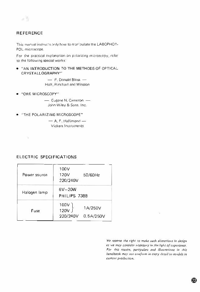
REFERENCE
This manual instructs only how to man ipulate the LABOPHOTshy
POL microscope
For the practical exp lanation on po lar izing mi croscopy refer to the following special works
bull AN INTRODUCTION TO THE METHODS OF OPTICAL CRYSTALLOG RAPHY
- F Donald Bloss Holt Rinehart and Winston
bull ORE MICROSCOPY
- Eugene N Cameron John Wi ley amp Sons Inc
bull THE POLARIZING MICROSCOPE
- A F Hallimond shyVickers Instruments
ELECTRIC SPECI FICATIONS
100V
Power source 120V 5060Hz 220240V
Halogen lamp 6V-20W
PH I LIPS 7388
Fuse 100V 120V
1A250V
220240V O5A250V
We reserve he righ to make such alteratioTlS in design as we may consider ncct$$l1ry ill the I(th of experience
For this rCaSO porlculars and ilitlSlraliorls in this handbook may nUl con[oTm in every detaito models in cucn( production
CARE AND MAINTENANCE
o Cleaning the lenses To clean the lens surfaces remove dust using a soft brush o r gauze Only for removing f inger marks or grease should
soft cotton cloth lens tissue or gauze lightly moistened with absolute alcohol
(methano l or ethanol) be used For cleaning the objectives and immersion oil use only xylene Observe su ff icient caut ion in handling alcoho l and xylene
f) Cleaning the painted surfaces Avoid the use of any organic solvent (for example thinner ether alcohol xylene etc) fo r cleaning the pa inted surfaces and
plastic parts o f the instrument
)Never attempt to dismantle Never attempt to dismantle the instrument so as to avoid the possibility of impairing the opera t ional efficiency and accuracy
O When not in use When not in use cover the instrument with the accessory viny l cover and store it in a
placeJree from moisture and fungus It is especially recom mended that the objectives and eyepieces be kept in an airtight con tainer con tai ning desiccant
o Periodical checking To maintain the performance of the instru shyment we recommend to check the instru shyments periodicall y (For details of this check contact our agency )
CONTENTS
I NOMENCLATURE
II ASSEMBLY
III PREPARATION 1 Interpupillary Distance Adjustment
2 Diopter Adjustment 3 Optical Path Change-over in the
Trinocular Eyepiece Tube TP
4 Centering the Objectives 5 Centering the Condenser Lens 6 Orientation of the Dia-polarizer
IV MICROSCOPY 1 Operating Procedure 2 Manipulation of Each Elemen t
1) Focusi ng
2) Co ndenser aperture diaphragm 3) Field diaphragm 4) Circular graduated stage
5) Objectives 6) Eyep ieces 7) Achromat strain-free condenser 8) Bertrand lens
9) 14 A amp tint plate 10) Dia-polarizer and analyzer
11) Filters 12) Illumination system
V PHOTOMICROGRAPHY
VI ACCESSORIES 1 5enarmont Compensator 2 Quartz Wedge 3 Monocular Eyepiece Tu be AP 4 Universal epi-illuminator
5 Attachable Mechanical Stage Type E 4f)
VII TROUBLE SHOOTING TABLE W REFERENCE ) ELECTRIC SPECIFICATIONS )
(j) (j) o o ~ ~ Ql Ql Ql Ql I) I)
~ ~ ~
~
~ ~ ~ 4l)4ll
I NOMENCLATURE
Binocular eyepiece tube BP
Interpupillary distance scale Eyepiece tube clamp screw- ---
Diopter ring
Centering nosepiece
----~ CF Achro~ma~t~P~o~~~~_ ____ (strain~free )
Circular stage
Circular graduated stage clamp screw
Vernier
Achromat strain-fr ee conde nser
CF
Bertrand lens I
Analyzer inout knob
Intermediate tube clamp screw
Coarse knob
Fine focus knob
Orientation plate
Filter receptacle
Fig 1
Analvzer rota t Ion ring
In termed iate tube P
Analyzer clamp screw
Compensator slot
14 amp tint
Condenser focus knob
Nosepiece centering screw
clip
Torque adjustment ring
Lamp socket
Field diaphragm control ring
V-POL stand
~ rotation clamp screw
Condenser centering screw
Condenser aperture control ring
Condenser clamp sere
Field lens
Brightness control dial
(including power switch)
Fig 2
o
II ASSEMBLY
bull To assemble the microscope follow the procedure in the order given
Bottom of the Base CF eyepiece ~ ~=-n-se~~t~th-e-ey-e- ie-c-e-C=-=FWCC--=O-p X-C-M--~reg into the right-hand sleeve fitting
sta
the pin of the eyepiece in the right-h and no tch o f the sleeve Into the left-hand sleeve insert IheCFW l Ox 1111 I G
I bull - ~~
reg~1~4~A~amp~t_intpl~at~e____~____~ Remove the screw by the side o f the 14 A plate o f the 14 A amp tint plate and insert it into the co mshypensator slo t of the in termediate tube P facing the posit ioningInput voltage change-over groove t oward the operator side
switch Reatwch the removed screw (For European districts only)
sure power source ~C~ ~ ~at~p ~____________~F Ac h~r~om ~ ~O~b~je=-C~t~iv~e __________~vol (age 220V or 240V by means reg ----shy
of the input vUl wge change-over Mount the objectives on the nose-switch on the bottorn of the piece in such posi tions that their roicroscopp bnse mvgnifying power increases as the
nosepiece is revolved clockwise
Bottom of the Bas8 I -=Scp-=-~ n~ _ _ ~-eci me~ c lip_ ___ ~
Place the clip on the stage using ho les on t he swgc surfClce Stage clamp sclew-----I1JIl
~1i~i~i~~~~~m~~~t~e~~t~t~he~St~~g~e~o~n--1 the circu lar d ovetail o f the subshystClge Clamp the sc rew
microscope mnn ipulJte th rllt shyjng screw at on~ foot on the bottom o f the microscope base
2 Achromat condense nsen 10 con shy
denscr facin g Ihe apertu re number p late toward the operator Fasten the clamp screw on the left side of the carrier
Aperture number pl _ _ ____J
-=Dia-p -Iar--- r -- - taJ --- shy-=-c---o iz---e --------- -Gmfl23~After centering th e objec shyt ives and condenser insert the dia-polari7er in lO the bottom of the condenser
(J) Eyepiece tube
Attach the eyepiece [Ube on the intermediate lUbe p fitting the notch o f the circular dovetai l on the end of the clamp screw Fasten the clamp screw
Eyepiece tube clamp screw
regIntermediate tube P
1 Atlach the intermediate tube P un the arm o f t he V-POL stand fi lling the notch of the c ircular dovetail on the end at [he clamp screw Fasten the clamp screw
ntermediate tube clamp screw
Power source
Halogen lamp bulb (6V-20W)
In se rt the lamp bulb with its pins into the accePting holes in the socket Note Dont touch the bu lb surshy
fa ce direct ly with the finshyger
reg Lamp socket - Insert socket into the recep shy
tacle on the rear of the baSElL - lte-___ _FiO r Place the filler on the fie ld tens q 45
Fig 3
III PREPARATION
1 Interpupillary Distance Adjustment
Place a spec imen on the stage and focus on the specimen
A s shown in Fig 4 ad just the interpupill ary
d istance so tha t both the righ t and le ft viewshyfields become one
Fig 4
2 Diopter Adjustment
Ro tate the d iopter ring on the eyepiece CFW
l OX e M until the cross lines are seen clear (Fig 5 )
Diopter ring --
Fig 5
(For b inocular observa t ion) 1) Mount the specimen on the stage Swing
the objective l OX into position and bring the specimen image into focus looking into
the right-hand eyepiece 2 ) Without manipulating the coarse-and-fine
focus knob turn the diopter rtng on the left-hand ey epiece to focus on the specimiddot
men
3 Optical Path Change-over in the Trinocular Eyepiece Tube TP
(Fig 6)
Vert ical photo 1 tube 86
Observation Observat ion ~~~Jl~ tu be 100 tu be 14-OPtical pltlIh shy
change-o ver knob
Fig6
I Since Ihe CF eyep ieces are of high eyemiddot
po int ty pe i t is no t neCe55ary for the user
putting on his spectacles to remove them Only fo ld down the eyeguard rubber
(F ig 8)
Fig 7 Fig 8
4 Centeri ll9 the Objectives
1) Place t he specimen on the stage and rocus on the specirnen Bring all appropriate tarshyget 10 the center of the cross lines in the eyep iece
2) Inser t the cen ler ing tools in the cente ri ng screws on the nOSlpiece (Fig 9)
Cen te ring screw
3) Rotate the stage about 1800
and the target is displaced from the center of the cross lines Move the objective using the centershying too ls so that the center of the cross lines comes to one half position of the
disp lacement of the target IF 19 10)
~ Rotate =4180middot -+--- -t
-~~ A hal Target- ------- posItIon
of the displacement
Fig 10
bull Repeat the above procedure two or three
times and the ro tat ion center of the stage coincides with thl cross lines center
bull Carry out centering for each objective
15 Ce ntaring the Condenser Lens 1) Close the field diaphragm in the microshy
scope base to its smallest site by means of
the field diaphragm control ring Ro tate the condense r focus knob to move the condenser vert ically so that a sharp image of the f ield diaphragm is forrned on the
specimen surface 2) Bring the field dia phragm image to the
center of the field of view by means of the condense r cen teri ng screws
(Fig 11 -lfl )
3) Ctlange over to the objective 40x cmd adjust the field d iphragm so that the image of the diaphrag m is about the same as the eyepiece viewf ield stop as shown in Fig 11 -~ If not centered use t he conshydenser centering screws again
Image of field diaphragm [
~LEyepiece ---- Ill Eyepiece
viewfield StOP viewfield stOP
Fig 11
6
1)
2)
3)
Orientation of the Dia-polarizer
Plac the specimen on the stage focus on the specimen using objective 40 X Set the ana lyzer scale on the intermed iate
tube P to O I nsert the dia-po la rizer into the bottom of the condenser as shown in Fig 12
Oia-polarizer shy
Fig 12
4) Remove the eyep iece from the sleeve
Observing the exit pupil of objective inside rotate the dia-polarizm so as to
form a dark cross image on the exi t pupil as shown in Fig 13
Dark cross image
Fig13
IV MICROSCOPY
r1 Operating Procedure bull
1) Turn the brightness control dial (including power switch) to light the lamp
2) Bring the analyzer and the Bertrand lens out of the optical path (Refer to P 13 amp 14)
3) Place the specimen on the stage and swing the 10X objective into position Focus on specimen
4) Adjust the interpupillary distance and diopter (Refer to P 8)
5) Place the filter on the field lens
6) Carry out the centering procedure for the objective (Refer to P 8)
7) Carry out the centering procedure for the conshydenser (Refer to P 9)
8) Bring the analyzer into the optical path
9) Swing in the objective to be used and refocus on specimen
10) Brightness voltage
IS adjusted by changing the lamp
Table 1
Orthoscopic microscopy
Conoscopic microscopy
Top lens o~
lO X or higher IN
IN condenser 4 X or
lower OUT
Bertrand lens OUT IN
Aperture diaphragm
lOX or higher
70 -- 80 of the numerical aperture of the objective
Circumscribed the circumfermiddot enee of the conoscopic field of view (or fully opened)
4 x or lower
Fully opened
Field diaphragm
lO X or higher
Circumscribed the ci rcumference of the eyepiece field of view
Circumscribed the circum fermiddot enee of the orthoscopic field of view 4 x or
lower Fully opened
2 Manipu lation of Each Element
1) Focusing
bull The re lation between t he direction of rotamiddot tion o f the focus knobs and that of vertical
movefnent of the stage is as ind icated in
Fig 14
Torque adjustment ring
Fine focus knob----+l~
= bull
Fig14
bull One rotation of the fine focus knob moves
th~ stage 02mm
The graduation on th is focus knob is
d ivided into 2um
One rotation of the coarse focus knob
moves the stage 47mm
bull The range of coarse and fine motion is within 30mm 2mm up and 28mm down
from the standard post ion
Tension of the coarse focus knob tightens
by turning the torq ue adjustment ring
counterclockwise
Never turn the right or left knob wh ile
holding the other
2) Condenser aperture diaphragm (A diashyphragm)
(1) Orthoscopic microscopy
bull The condenser aperture d iaph ragm is p rovided for adjusting the numerical
aperture (NA) of the illuminating system
of microscope
In general when it is stopped down to 70 - 80 of the n~~-Pt-~ re of the
objective a good image of appropriate
contrast will be obtained (F ig 15)
- Exit pupil of objective
Aperture diaphragm
Size of the condenser aperture diaphragm
Fig15
bull Remove the eyepiece from the eyepiece
tube adjust the Si78 of the diaphragm observing the image of the diaphragm
which is visible on the bright circle of exit
pupil of objective inside
bull When swinging out the top lens of the conshydenser (for rnicroscopy using 4X or lower
objective) fully open the condenser
aperture diaphragm (2) Conoscopic microscopy
bull In conoscopic microscopy the condenser aperture diaphragm works as a field diashy
phragm on the conoscopic image surface
Stop down the diaphragm to such an
extent that it circumscribes the circumfershy
ence of the field of view of the conoscopic
image (exit pupil of objective) to shut out
the stray light
3) Field diaphragm (F diaphragm)
bull The field diaphragm is used for determinshying the illuminated area on the specimen
surface in relation to the field of view of
the microscope Generally it is stopped
90wn to such an extent that the circumshy
ference of the illuminated area circumshy
scribes that of the eyepiece field of view
[Note] This diaphragm does not work as
the field diaphragm when the
condenser top lens is swung out
of the optical path In this case
the diaphragm is recom mended
to be fully opened because the
numerical aperture of the illumishynator will be cut off when this
diaphragm is excessively stopped
down
4) Circular graduated stage
bull The rotat ion angle o f the stage is readable with the accuracy of 0 10 via a vern ier scale
bull The stage can be cl amped at any position using the stage rotation clamp screw on the vernier
5) Objectives
bull The CF Achromat P objectives (Strain-free) and CF eyepieces adopted in the Nikon POLARIZING MICROSCOPE LABOmiddot PHOTmiddotPOL are designed on the basis of a concept Chromatic Aberration Free In every case use the CF objectives in comshybination with the CF eyepieces
(1) Oi l immersion objectives (Oil)
bull Object ive CF Achromat P lOO X (Oil) an oil-immersion type is to be immersed in oil between the specimen and front of the
objective To see if air bubbles are present in the im shymersion oil which deteriorate the image quality pullout the eyepiece from the eyepiece tube to examine the objective ex it pupil inside the tube To remove air bubshybles revolve the nosepiece slightly to and fro several times apply addit ional oil or repla ce the oil Be careful not to rotate the nosepiece too far as to soil the ends of the other objectives with oil
bull To clean off the oil pass le ns tissue or so ft cloth moistened wi th xylene lightly two or three times over th e lens It is essent ial at this time to avoid touching the lens with the part of tissue or clo th once used
(2) Coverglass bull With the objectives engraved 160017
use a cOlJerglass of O1 7mm in thickness bull The indicatio n ---160- on the objective
means that no matter whether a coverg lass is used or not no decrease of image defini shytion or of co ntrast will result
5 Eyepieces
bull To take full advantage of the CF eyepieces use them in combination with the CF objectives
bull By inserting the eyepiece with cross lines and graduation (CFW 10 XCM) into the eyepiece sleeve fitting the protractor pin into the right-hand side groove of the sleeve the Omiddotdirection of the analyzer and dia-polarizer are aligned with the cross lines direct ion If the protractor pin is fitted to the upper right side groove of the sleeve the cross lines will be aligned with the diagonal posishytion of the polarital ton
bull CF PL Projection lenses are exclusively designed for photomicrography Do not use them for observa tion
bull For focusing with the observation tube of the trinocular eyepiece tube for photoshymicrog raphy use the eyepiece incorporatmiddot
ing the photo mask
7) Achromat strain-free condenser
bull The top lens of the condenser is to be placed in the OPtical path for the orthoshyscopic and conoscopic m icroscopy providshyed that it is to be swung out when an objective of 4X or lower magnif ication IS
in use iNote] For the orthoscopic microscopy a
lower numenc~1 aperture illumlna ~
tion w ith the top lens swung out
condenser was used t o be recom shymended however this method is not effective especially for high magnification observation because of the lowered resolution Hence for the latter case use of the top lens may rather be recommendshyable except the retardation meashysurement or the interference color observatIon for which it is necesshysary to make the illum ination light flux as parallel as possible to the optical axis by swinging out the top lens or stopping down the aperture diaphragm
bull Thickness of the glass slide must be 17mm or less otherwise the f ield diaphragm
might fail to focus its image on the specishy
men
8) Bertrand len (with the tnnocular eyepiere tube TP or
t he b inocular eyep iece tube BpI in use)
bull Bring the Bertrand lens in tO the opt ica l path by turning the BertrEJnd lens ring
leftward to observe the conoscopic image
(F ig 16)
Bertrand lens flip -inout ring
Fig 16
bull The conoscopic view fi eld is as large as
about 14 of the orthoscopic view fi eld (Fig 17)
Conoscopic image of th is area can be
observed( shy
~ r-- OrthoscopIc vlewf leld
Pin hole eyepiece
Fig 18
In the above simu ltaneuus observatIo n of
the conoscopic and o rthoscopic images
the former image may appear deviated
from the orthoscopic view field center
however the devi ated image represents
the conoscopic light fl ux that cevers the
cent ral part of the orthoscopic view f ield
to the extent of about 1 18
9) 14 X amp tint plate bull Removing the 14 A plate side screw ho ld
the 14 X amp tint plate the c lickmiddotstop groove facing the operator an d inser t it
forward into t he compensator slot
Then sc rew-in the above screw as i t was
(F ig 19)
Fig 17
bull The conoscepic image may also be observshy
ed overlapping on the orthoscopic image
through the binocular observation one o f
the paired eyepieces being rep loccd wi th
the accessory pin hole eyepiece and withshy
out the Bertrand lens In th~ uPtical path (F ig 18)
14 i plate
t4X amp tint plate
Fig 19
bull The tint plate has an em pty ho le at the
center By pushing it th rough the slOt the
sensi tive t int p late (530nm) is brought
into the optical path and by pulling i t out
the 14 X plate is brough t into the optical path
10) Dia-polarizer and analyzer
bull When the both are set at Q reading on the protractor scale position of the polarizashyt ion planc coincides with the orientation
plate (X-direction for polarizer V -di rection for analyzer) on the microscope base
(Fig 20)
[Note] Some of the reference books or specia l works about polar izing
microscope available in the m~rket explain that X-direction is for analyzer and Y -di rection for polar7er
-shy
ip ~~-~ Orientation plate
(~~ -
1 ~ Fig 20
bull As the orientat ion of the dia -polar izer slight ly changps when centering t he conshy
denser check the orientation after centershying the condenser
bull The analyzer rotates 1800 via the rotat ion ring the left-hand side clamp being releasshyed The rotation angle is readable with accuracy of 01 Q via the vernier
Analyzer clamp
Anal yzer rotation ring
inout knob
Fig 21
11) Filters
bull Place the filter on the field lens
Table 2
Type 01 f il ter Use
B (Day light) For general microscopy
GIF For retardation measureshy(Green interference) ment
12) Illumination system bull The oPtical sys tem for Illumination in the
LABOPHOTmiddotPO L microscope is constructmiddot ed to fulf ill the Koehler illumination requirements perfect ly and offers a bright
uniform f ield w ithou t any change-over manipulation
bull Halogen la fllp 6V-2(JN (PHI LIPS 7388) is used as a light sou rce
V PHOTOMICROGRAPHY
Prepare the following cquipmc nts in fJdui tion to
the LABOPHOTmiddotPOL microscope rna in body
Nikon Microflex Tr inocular eyepiece tube TP CF PL Projertion Lens
1 C F P L Projection Lenses
The combined use Of the CF P objectives and CF PL Projection lenses is essentiaL For the same total magnification select a comshybinat ion of the hiQhest possible objective power and lowest possib le pruject ion lens power to ach ieve the utmost image definit ion and contrast
2 Illumination
) Checking the illumination Unevenness in the il lumination will show up more conspicuously in photomi croshy
graphy than in observation Consequently before tak ing a photugraph recheck the
positioning and centerinn of the lamp and the correct adjustment of the condenser
2) Selection of voltage and filter The color tempera ture of the l ight sourCB var ies with the vo rtage be ing used Thereshyfore in co lor photomicrog raphy the selection of voltage ano f il ter is essential
(for the result to be obtDinedl
In color photomicrography set the brightshyness contro l dial to 55 and use NCB10 fi lter Depend ing upon the make of the film
bull different color rend itions mDy result I t IS
recommended that in addition to the NCB 10 filter a co lor compensation fdtcr (CC
filte r) avai lable fr om the film manufac
turer be used
3 Shutterl =-____ _ _SIpeed=
Desirable shutter speeds fo r least vibration are 14 - 1 15 sec Adjustment of the imJge brightshyness for color photomicrography should be made by means of the NO fi lters Some specimens require on arcount of their
insu ff icient bri ghtness longer exposure times and conseq uently poor color rep roducibility owing to the Reprocity Law Fai lure of f ilm may result So when taking picture of such spec im ens i t is recommended to use the Ni kon Pola rizing Microscope OP TIP HOTmiddotPO L
In photomicrography the adjustment of the f ield d iaphragm is impo rtanr for the purpo~ of limi ting extraneous light which causes fl are In
the m icroscope image Stop down the diashyphragm so as to get an illuminated area sligh tly
larger than that of the picture field By adjustshying the aper ture diaphragm a change of dep th of focus contrast and resolution of image is attainable Select a size suited to the purpose
Genera lly speaking the aperture diaphragm is properly Slopped down to 70 - 80 of the
aperture of t he objec tive being used
[5 Focusing Focusing for photomicrograp hy can be done with the observation tube of the trinocu lar
eyepiece tube TP or by using the Micrn flex finder
1) For focusing with the Microflex finder
Refer to the Instruction Manual for the Nikon Micro flex
2) Focusing with the observation tube For focusing with the observation tube use til e eyep iece incorporat ing the photo mask Befo re prorecdlnQ to focusing the b ino shyCll iar d iopter adjustment shou ld have been fini shed
(1) Insert the eyepiece with photo mask Into the eyep iece sleeve on the side of (he users
dominant eye and the viewing eyepiece into tile other Side sleeve Turning the diopter ring bri ng the doubie cross li nes in th~ mask eyepiecr into ~t larp focus CJnd then turn ing the coarse-fine f ocus knob focus the specimen image onto the focused surfClce at the (en ler of the
mask For diopter adjustment in the other eyepiece do not manipulate the focus knob but the diopter ring to bring the image into focus with the objective 4 X or lO x
(2) Turning the eyepiece as a whole set it in such a position that the photo mask apmiddot
pears as shown in Fig 22
--Inner frame
Intermediate frame
- Outer frame
Mask eyepiece viewfield
Fig 22
(3) Furthermore when using a low power objective place th e focusing telescope over the mask eyepiece thus constructing an eyepiece of higher magnification to permiddot form precise focusing
3) Magnifications of CF PL Projection lenses suitable for each frame size of photo mask
Refer to Table 3
Table 3
For photomicrograp hy when fOCUSing with the binocular observat ion tube use
the CF eyepiece CF PL Projection lens and
CF Photo Mask eyeplece w ith the magnifi middot cat ion and other indications eng raved in yellow or in white w ith a white dot in addition
6 Others bull As the intermediate tube P of LABOmiddot
PHOTmiddotPOL microscope builts in the depolariLer its not necessa ry to give Care
to the relation between the orientation o f the polarizer analy zer and the position of the Microflex
bull For the use of other photomicrographic attachments refer to the pertinent instrucmiddot tion manuals
Mask CF PL
Pro jection lens
Film SI 2e
35 mm
6 X9 em
3Y X 4
4X 5
Inner frame
2 x x - -25 X - -
4 X 1) -
5 X 0 - 1nter middot mediate frame
2 x X - -25x 0 -4 x
0 X
0 - -- -
OUler frame
2 X x 11) -25 X I) - - 0
4 x - - -
5 X - - - -
Note Framing for picture composi ng wi ll
be mOre accurate by the ocular fi nder than the mask eyepiece
VI ACCESSORIES
1 Senarmont Com ensator To be inserted into the compensator slo t of the intermediate tube P in p lace of the 1 4 A amp tint plOl te to measurr ttu retardatio n with the accuracy of the ~ uM (F ig 23)
Fig 23
1 ) Detecting of extinction position Rotate the stage with the specImen under the crossed Nicols to find out the d irection where the specimen part for measurement appears darkest
2) Detecting of subtraction position Rotate the stage 45
0 to br ing it to the diashy
gonal posit ion f rom the extinction posit ion and confirm that the interference cot or of the specimen part for measurement changes toward the lower o rder side by inserting t he 14 ~ amp tint plate into the opt ical path If the co lor changes toward h igher order side rota te the stage further by 90
0
3) Measurement Inserting the filter GI F into t he filter receptac le replace the 14 ~ amp tint plate by the compensator Rotate the ana ly zer so as the specimen part for measurement becomes as dark as possi shy
ble Let the ang le of the above analY7er rotamiddot tion be 8deg then the retardation A (nm) wi ll
be obtained as fo llows
8 A = --~
180
where ~ wave length o f the light used for the
measurement
When the filter GI F IS used ~ = 546nm
2 Ouartz Wedge
The Quartz wedge is used instead o f the 14 A amp t in t pl ate t hat is in the compensator slo t of
the in termed iate tube P (Fig 24) With this wedge the relardation in the range of 1~ - 6~ can roughly be measured
Fig 24
1 ) Detecting of extinction position
Detect the position where the sPecimen part for measurement becomes darkest by rotating the stage under the crossed Nicols
2) Detecting of subtraction position
Rotate the stage 45deg to bring it to the diamiddot gona l position from the extinction position and confirm tha t the interference co lo r of the specimen part for measurement changes toward the lower order side by inserting the quartz wedge into the optical path If the co lor changes toward the higher o rder side ro tate the stage further by 90deg
3) Measurement By slid ing the quartz wedge along the slot the interference co lor changes consequentshyly
The wedge sliding is to be stopped when the sPecimen part for measurement comes under the dark stripe then compare the
interference colo r of th e view field beyond the specimen but under the same dark stripe wi th the Interference Color Char t to
assume the amount o f retarda tion If the view f ield is entirely f illed with the specimen around the part to be measured restr ict the illumination of the view field except around the part for measurement by means of the fie ld diaphragm remove the specimen away the optical path and then compare the interference co lor wi th the chart
Pin hole swing-inout knob
Lamp ho using clamp screw
RS~---F eld diaphragm ri ng
~~IIC----Polarize r rotation ri ng
Intermediate llJbe clamp sClew
3 Monocular Eyepiece TubeAP
Bertrand lens ~
inou t tu rret -1-lt~~~~~=1 Bertrand lens focus turret
Fig 25
) Bertrand lens
The Bertrand lens is brought in and out of the OPtical path by turning the Bertrand
lens turret The lens is in the OPtical path when the
indication on the turret is B T he Bertrand lens can be focused by turnshying the focus turret located under the Bertrand lens turre t
2) Pin hole knob
T he pin ho le can be put in or out of the
oPtitCli pltJth by operat ing t he pin hole knob located right middothand Side of the eyeshy
piece sleeve By means of the pin hole the conoscopic image cover ing the area of 10Jlmcent on the specimen surface (when a 100X object ive is used) can be observed
Universal epi- ill uminator ----
Optical -path change-over knob _ ___-
Dust-tight slider-----
4 Universal epimiddot illuminator Used for episcopic polarizing microscopy
mounted between the Y - PO L stand and the
intermediltJ te tube P
1) Nomenclature
bull Referr ing to Fig 26 assemble in the order
given 11 Remove the eyep iece tube and the inter shy
ffl ed iJte luue P from t he V-POL stand CV Mount the universtll ep i- i llum inator on the
mi croscope arm pusit iun inn the illumishynator nearly pa ralle l to the arm Clamp the
screw (j) After releasing sufficient ly the clamp
screw on the lamp housing t o wh ich the lamp bulb ( 12V -50W Hologcn lamp) and
socket is attached insert the lamp hOUSing into the universal ep i-ill uminator and
clamp the screw Connect the lamp cord to the tra nstormer
s Remove the accessory ND32 filt er slider frum the illuminator Push in the polar izer
slider unt i l it cl icks twice
reg Place the fi l ters CD Mount t he in termediate tube P on the
illuminator fitting the notch of the ci rshycular dovetai l on the end of the clamp
screw Fasten 111e c lamp srrcw Referr ing to p 7 mount the eyepiece tube
on the intermediate tube P
~--Socke t sleeve clamp screw
~--Lamp lateral ce ntering screW
4 ~ I Transformer I
---lamp vertical centenng nng
Polarizer slider
Fig 26
2) Preparation
(1) Centering the lamp
Make certain that the optical-pa th changeshy
over knob is pushed (0 the limit
(Z) Turn ON the power SWitch on the transshyformer set the voltafle to 6V
Q) If the L900C fi lter is in the optical middotpath
remove th is
4 Fully open the aperture diaphrClgrn
(j Place the ND fil ter on the stc1qe and focus
o n it using objective lO X
~ Remove the eyepiece from the sleeve
look ing into the ex it pupil of objective move the lamp housing back and forth to
form a sharp image of the lamp filament on the diffuser o f exit pup il bull
f Manipulate the lamp center ing screws to
center the fil ament image on the ex i t pupi l
reg Place the L900C f il ter
If the image is found roo dark w ith an objecUv( of 40 X or higher remove the
L900C fi l ter
(2) Orientation of polarizer (intermediate tube P )
(j Nearly focus on the ND f il ter on tho 510ge
using object ive 40Xbull Z1 Set the polarizer graduat ion 10 0 ~ Remove one eyepiece f rom the ouservation
tubes bull Looking into the exit pupil of the object ive
rota te tho polan2er rotation nn~ to form
the dark cross irnaut nn t he ex i t pup il
(Refer t o Fiy 13)
Note Take care not to tourh the polamiddot
r izer rotation ring wh ile observing
the specimen or the or ientatlon
of the polar izer will get out of
order
If it is touched by m istake readmiddot
j ust the orien ta tion
3l Objectives Use the objectives CF M Plan Achromat P
bull series (Strain-free 210451
4) For manipulat ion ond microscopy refer t o
diascopic polari zing m icroscopy
5 Attachable Mech ical Stage Type E
To atlach the atHlchablc stCige nn t he graduated
stafjp fit t he two position ing pins on the rear
side of the attachab le stage Into the two pin
holes o n the graduated stage surface and clam p the screw using a drive r or a co in
Attachable mechanica l stage is eqUIpped with
point counters w hose pitch IS O2mm orO3mm
The counter ca n be replaced by relea SIng the
h ea~ of the pOint counter by m eans of a COin
ai1d removing the m illed part of the counter
To release the c lick-stop of the pornt counter
release the click sPrln9 nut (Fig 2 7)
spring nut Positioning pins
Attachable mechanical stage type E __lr-j--~II-~_=
Fig 27
VII TROUBLE SHOOTING TABLE
A lthough nowhere the user can fjnd any disorder o r derangement in the instrument if he
encounters some difficulty or dissatisfact ion recheck the use referring t o the tab le below
1 Optical
Fa ilu res Causes Actions
Darkness at t he bull Opt ical pat h in tr inocular tube bull Chang ing-over to the limit periphery or not fu lly changed-over (Refer to P 81 uneven brightshy bull Centering no sepiece not in click- Revolve it to cl ick-stop position ness of viewshy stOP position (Objective not
field centered in opt ical path) (No appearance bull Conde nser not centered Centering by using fi eld
of viewfield) d iaphragm (Refer to P 91
bull Field diaph ragm t oo much closed Open it pro perly
bull D irt or dust on the lens - Cleaning (Conden ser object ive eyepiece slide)
bull I rnproper use of cond8nser bull Co rrect use (Refer t o ~ 101 bull Bertrand lens in the optical path Fli p out (Refer to P 13 amp 181
bull Pin ho le in the optica l path Swing out (Refer to P 181 (in monocular eyepiece tube AP)
bull Top lens o f condenser incorrect ly Swing in to t he lim it
positioned
bull 14 A amp tint plate compensat or Correct sett ing
or quartz wedge incorrectly
positioned
Dirt or dust in bull Dirt or dust on t he lens Cleaning
the viewfield (Condenser objective ey epiece
f ield lensl
bull Dirt or dust on the slide Cleaning
bull Too low position of condenser Correct positioning
(Refer to P 91
No good image bull No covergl ass attached to sl ide Correct use ( Refer to P 121 obt ained (low or NeG obj ect ive used w it h covergl ass
resolution or bull Too thick or thin coverg lass Use specified thickness (0 17mml
contrast) coverglass (Refer to P 121 bull Immersion oil soils the top of dry Cleaning
system objective (especially 40 x I
bull Dirt or dust on the lens (condenser Cleaning
objective eyepiece slide)
bull No immersion oil used on immersionshy -- Usc im rnersion oi l
system object ive (Refer to P 121
bull Ai r bubbles in imm ers ion oil Remove bubbl es
bull Not speci fied immersion o il used middot Use Nikon imm ersion o i l
bull Co ndenser aperture o r field Open properly (R efer to P 111 diaph ragm t oo much opened
bull Dirt or dust on the entrance lens Cleaning
---
--
Failures Causes Acti ons
Image quality bull Condenser aperture too much closed - Open properly (Refer to P 11 )
deteriorated bull Too low posit ion of condenser Bring it uP to co incidence wi th
fi eld diaphragm image (Refer to P 9)
Oneside dimshy bull Center ing nosepiece not in cli ck-stop - Revolve it to cli ck -stop posit ion ness of image position
Image moves bull Specimen rises from stage surface Place i t stable while being bull Center ing nosep iece no t in cli ck-stop -----gt Revo lve i t to cl ick-stop posi tion focused posi tion
bull Condenser not correcrly cen tered bull Correct cc nlcring (Refe r to P 9) bull Optical path in trinocu lar Chtlnglng-over to the l im it
tube no t fully changed-over (Refer to P 81
Image tinged bull B filter not used Use B f il ter yellow
2 Manipulation
Failures Cau ses Actions
No focused bull Upside down of sl ide- Turn over thc slide middot bull Too t hick covergl nss Use specified thi ckness (0 17 mm l
with high pow-image obtained
coverglass (Refer to P 121
er objectives
High power obmiddot bull Upside down o f slide Turn over the slide
jective t ouches bull Too th ick coverglass Use specif ied thickness (O 17mrn)
th e slide when coverglass (Refer to P 12)
changed-over bull Eyepiece d iopter not ad justOr] - D iopt er adju stment
from low pow er (E special ly when changing-over (Refer to P 8) low power object ive2 X )
Insuffici ent bull Eyep iece di opter not ad justed D iopter adjust ment
parfoca li tY of (Refer t o P 8 )
objective (when changed-over
Movement of bull Attachable mechanica l stage not bull Fix it tightly
image not tightly f i xed
smooth by mov
ing the sl ide
No fusion of bull Interpup illary distance not bull Adjustment (Refer to P 8)
binocular adjusted
images
Fatigue of obmiddot bull Incorrect diopter ad justmenl Correct adjustment
serving eyes (Refer to P 8)
bull Inudequatc br igh tness of ChJnge power vo Itage
illumination
3 Electrical
Failures Causes Actions
lamp does not bull No electr icity obtained Connect the cord to socket light even bull No lamp bulb attached middotA ttaching t hough switchmiddot bull Lamp bulb blown Replacement ed ON bull Fuse blown Replacement
Unstable
brightness of illumination
bull House current voltage fl uctuates too much
Use transfo rmer or the like (for adequate voltage)
lamp bulb prompt ly
blown
bull Not specified lamp bulb used
bull Too high vo ltage o f house current
Use 6V-20W specified lamp bulb (Halogen bulb PHILIPS
7388) Use transformer for adjustment
Insufficient
brightness of
ill umination
bull Condenser not centered bull Condenser aperture too much closed -bull Too low position of condenser
bull Not specif ied lamp bulb used
bull Dirt on lens (condenser objective eyepiece fi el d lens fil ter)
bull Too low voltage
Centering (Refer to P 9) Open it properly (Refer to P 11 )
middot Correct posit ioning
(Refer to P 9) Use 6Vshy 2OW specif ied Halogen
bulb (PH I LIPS 7388) Cleaning
Raise the volt age
Fuse blown bull Not specified fuse used Use 1A250V or O5A250V
Flickering or I bull Lamp bulb going to be b lown I
unstable I bull Lamp socket not inserted brightness of sufficiently lamp bulb bull Fuse holder not firmly fastened
bull Irregular change of house current voltage
bull Lamp bulb insufficiently inserted into the socket
Replacement
middotSecure connection
Firm fastening Use stabi lizer
Posi ti ve connect ion
REFERENCE
This manual instructs only how to man ipulate the LABOPHOTshy
POL microscope
For the practical exp lanation on po lar izing mi croscopy refer to the following special works
bull AN INTRODUCTION TO THE METHODS OF OPTICAL CRYSTALLOG RAPHY
- F Donald Bloss Holt Rinehart and Winston
bull ORE MICROSCOPY
- Eugene N Cameron John Wi ley amp Sons Inc
bull THE POLARIZING MICROSCOPE
- A F Hallimond shyVickers Instruments
ELECTRIC SPECI FICATIONS
100V
Power source 120V 5060Hz 220240V
Halogen lamp 6V-20W
PH I LIPS 7388
Fuse 100V 120V
1A250V
220240V O5A250V
We reserve he righ to make such alteratioTlS in design as we may consider ncct$$l1ry ill the I(th of experience
For this rCaSO porlculars and ilitlSlraliorls in this handbook may nUl con[oTm in every detaito models in cucn( production
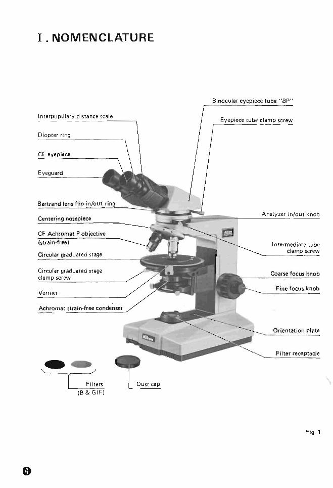
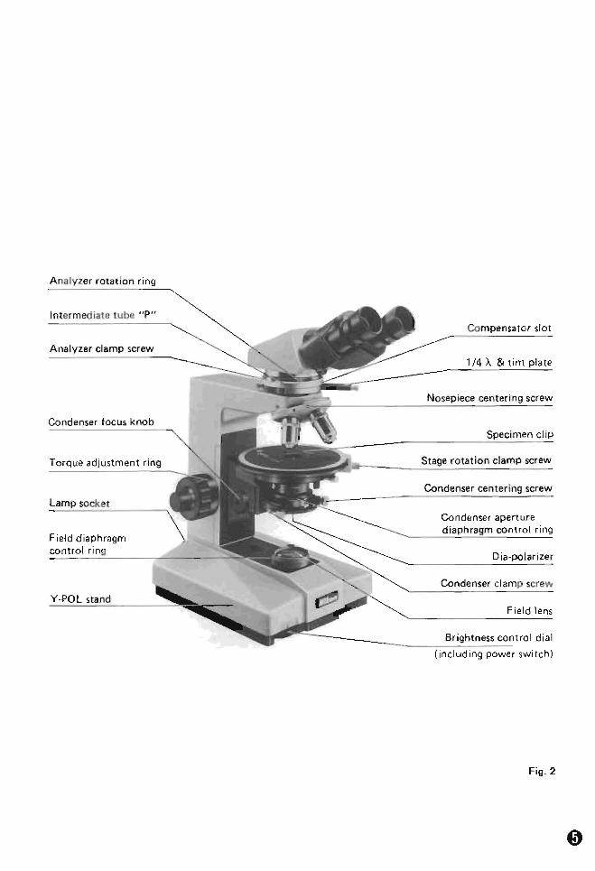
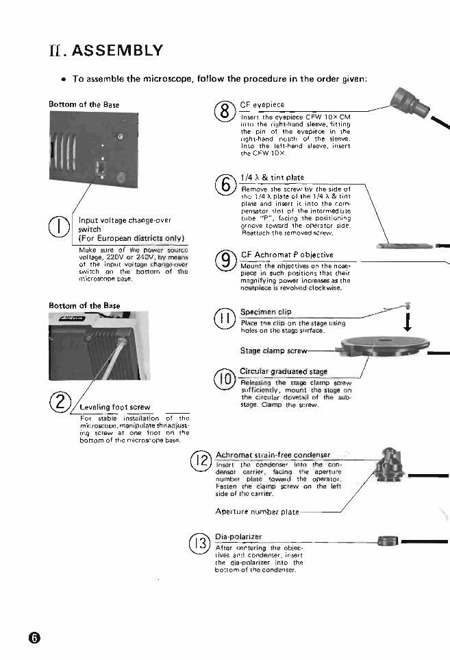
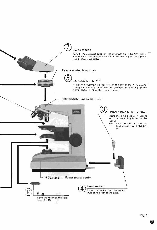
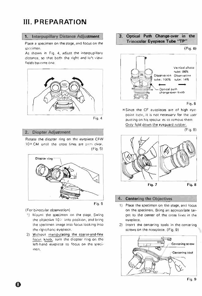
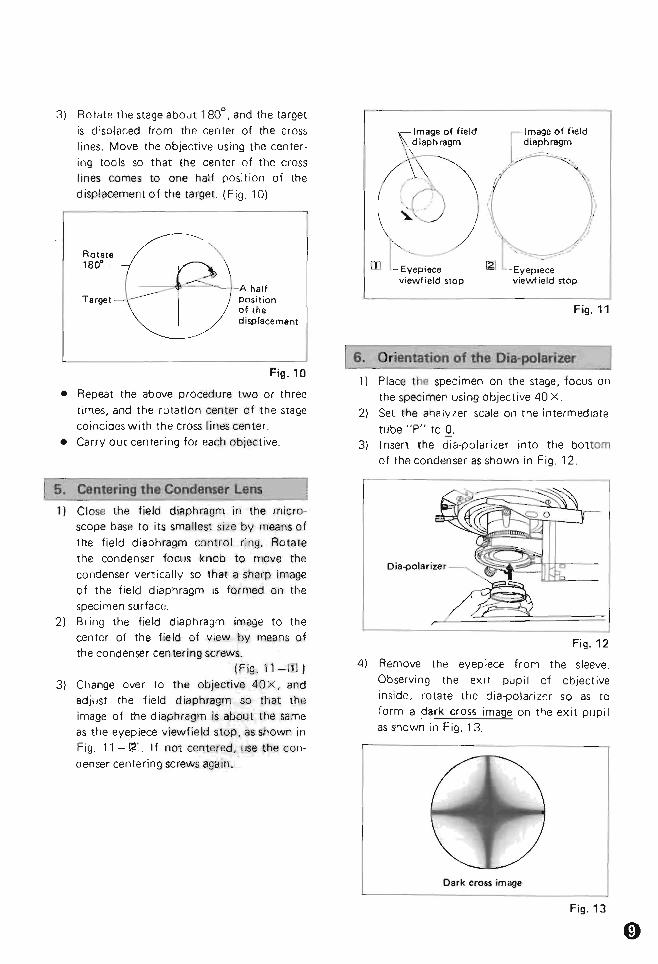
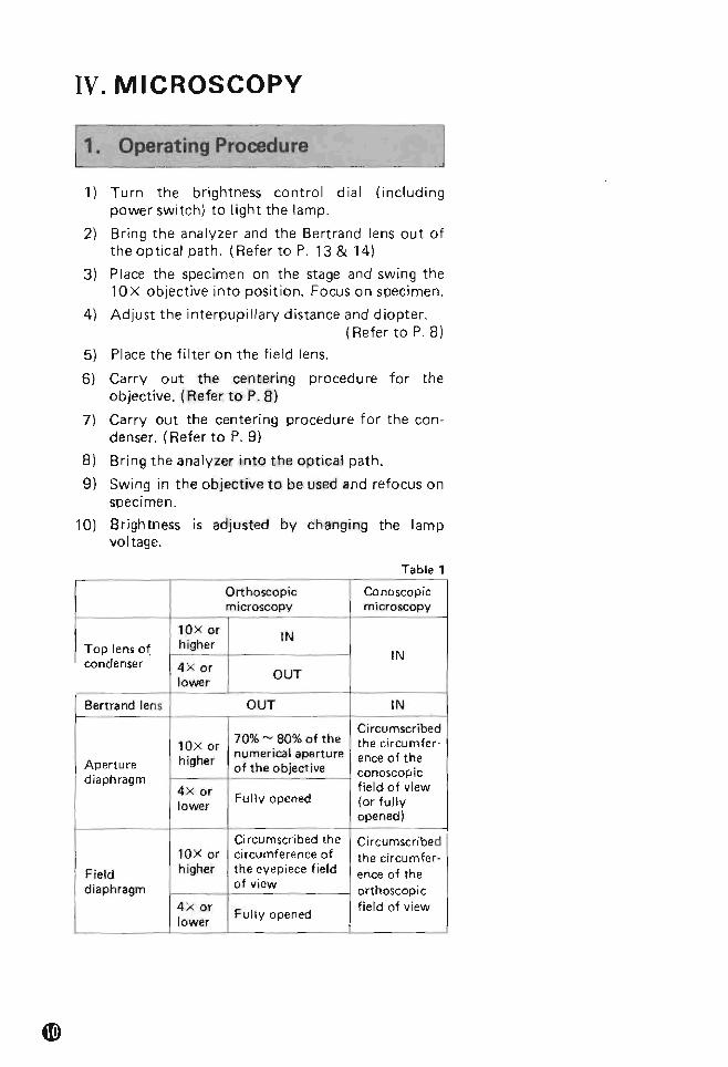
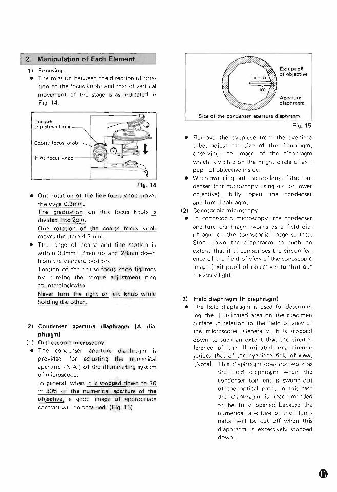
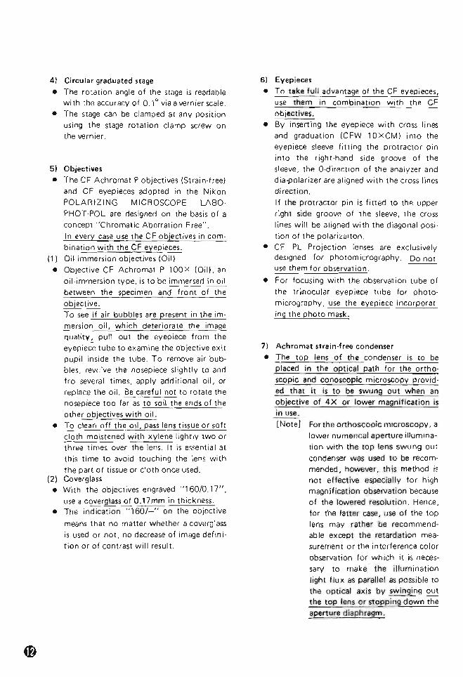
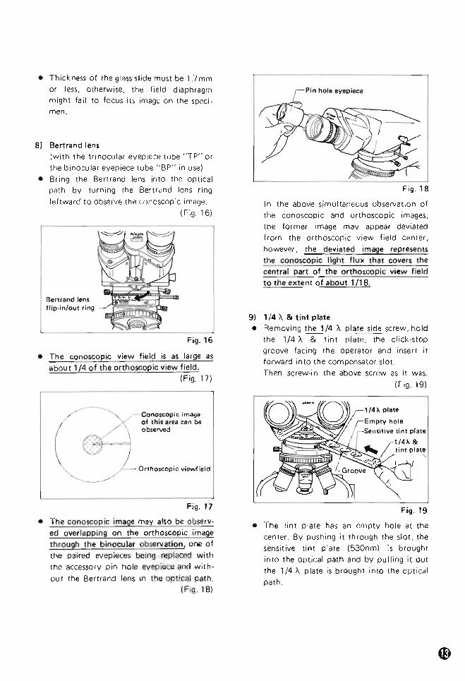
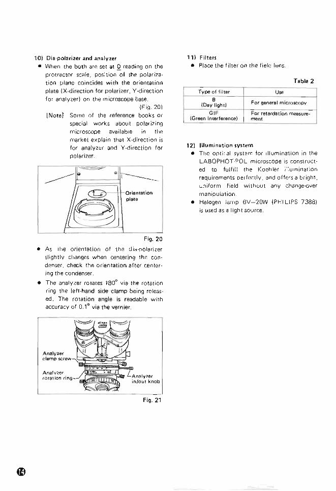
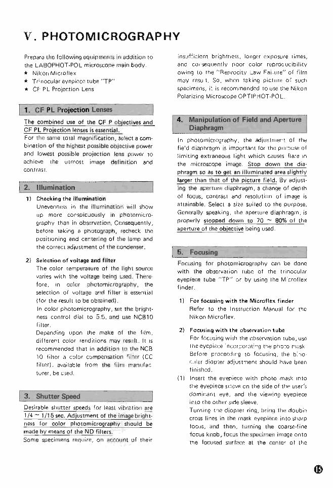
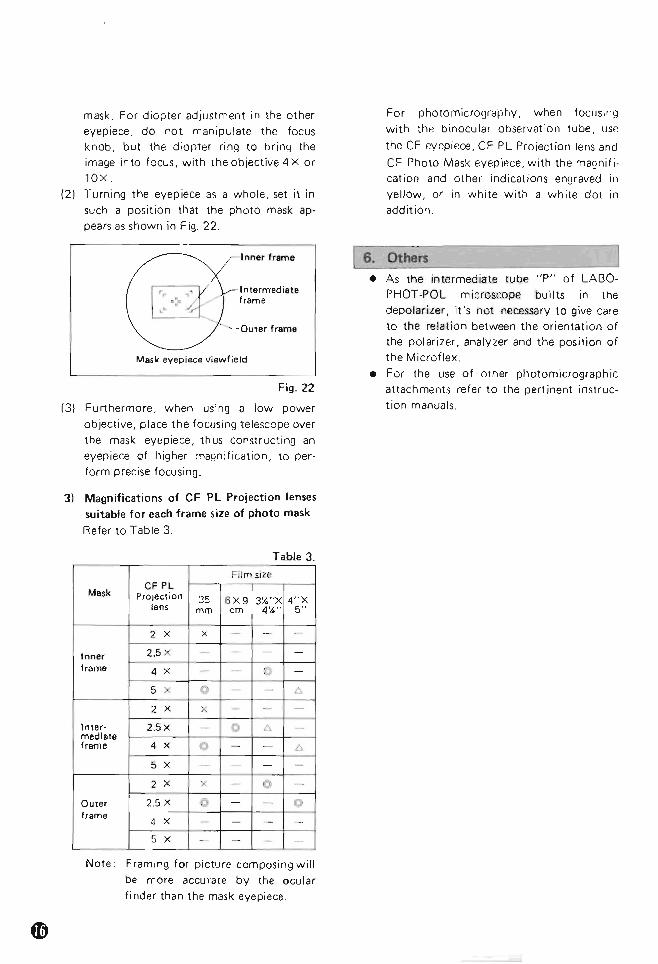
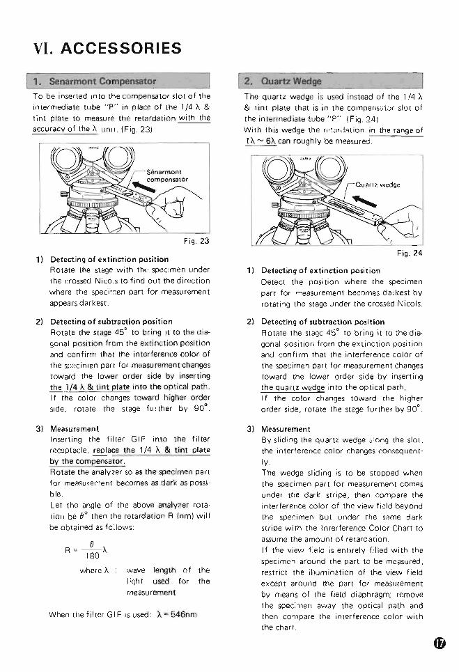
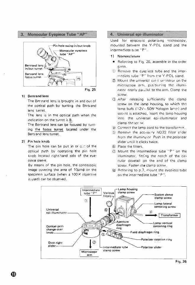
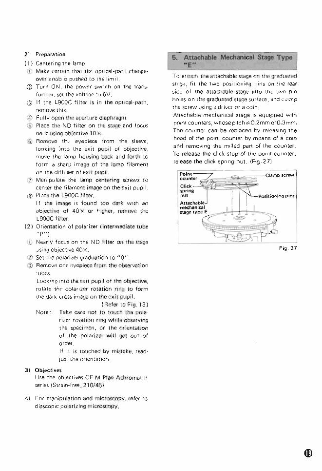
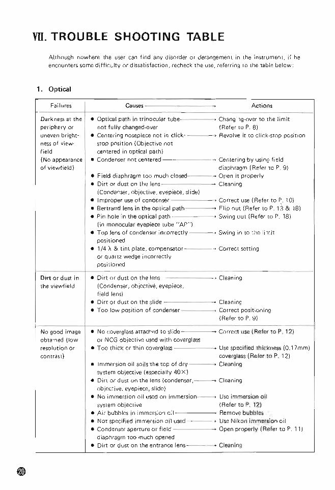
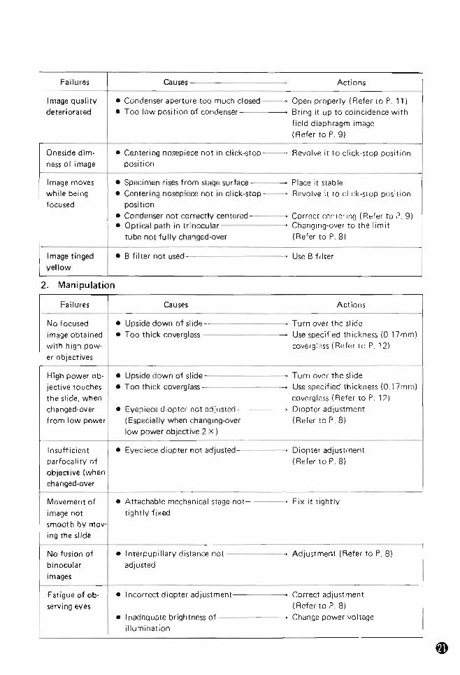
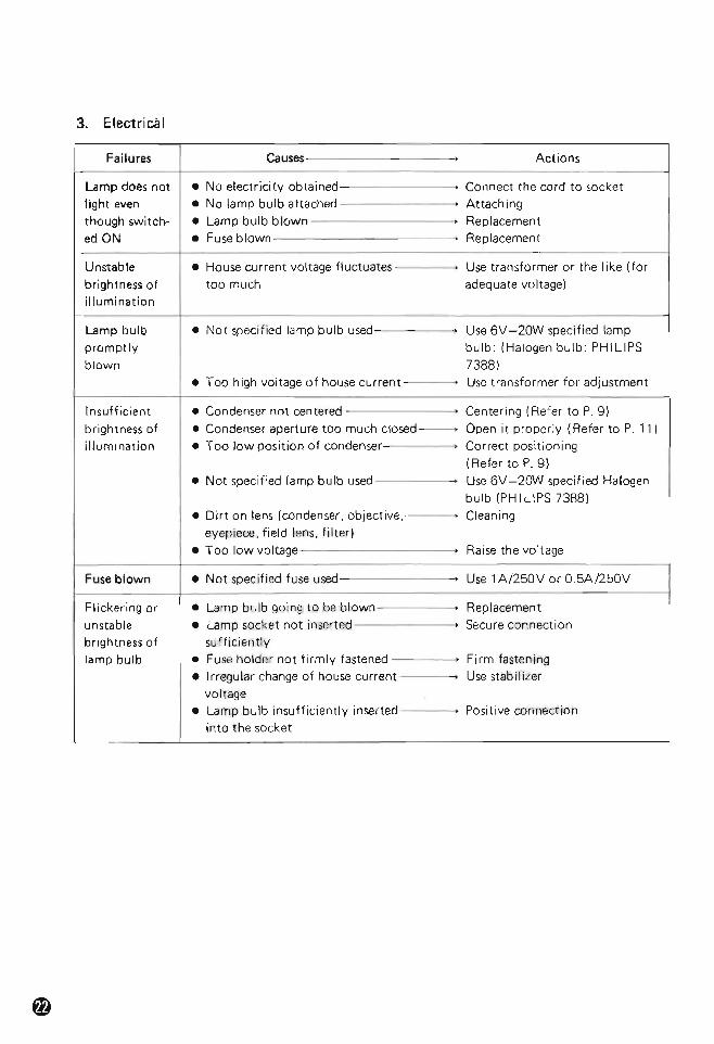