Embed Size (px)
Citation preview
Strain controll of magnetic anisotropy in (Ga,Mn)As microbars
C. King1, J. Zemen2, K. Olejnık2,3, L. Horak4, J. Haigh1, V. Novak2,
J. Kucera2, V. Holy4, R. P. Campion1, B. L. Gallagher1, and T. Jungwirth2,1
1School of Physics and Astronomy, University of Nottingham, Nottingham NG7 2RD, UK2Institute of Physics ASCR, v. v. i., Cukrovarnicka 10, 162 00 Praha 6, Czech Republic
3Hitachi Cambridge Laboratory, Cambridge CB3 0HE, United Kingdom and4Charles University in Prague, Ke Karlovu 3, 121 16 Prague 2, Czech Republic
(Dated: November 1, 2018)
We present an experimental and theoretical study of magnetocrystalline anisotropies in arrays ofbars patterned lithographically into (Ga,Mn)As epilayers grown under compressive lattice strain.Structural properties of the (Ga,Mn)As microbars are investigated by high-resolution X-ray diffrac-tion measurements. The experimental data, showing strong strain relaxation effects, are in goodagreement with finite element simulations. SQUID magnetization measurements are performed tostudy the control of magnetic anisotropy in (Ga,Mn)As by the lithographically induced strain re-laxation of the microbars. Microscopic theoretical modeling of the anisotropy is performed basedon the mean-field kinetic-exchange model of the ferromagnetic spin-orbit coupled band structure of(Ga,Mn)As. Based on the overall agreement between experimental data and theoretical modellingwe conclude that the micropatterning induced anisotropies are of the magnetocrystalline, spin-orbitcoupling origin.
I. INTRODUCTION
Dilute moment ferromagnetic semiconductors, such as(Ga,Mn)As, are favorable systems for studying and utiliz-ing controllable magnetic anisotropy since micromagneticparameters of this ferromagnet are very sensitive to Mndoping, hole concentration, lattice strains, and temper-ature. The magnetic moment density is small in theseferromagnets and therefore the spin-orbit coupling in-duced magnetocrystalline anisotropy typically dominatesthe dipolar-field shape anisotropy.
The control of the magnetocrystalline anisotropy in(Ga,Mn)As epilayers has been achieved by choosing dif-ferent substrates and therefore different growth inducedstrain in the magnetic layer, by varying the growth pa-rameters of the (Ga,Mn)As film, and by postgrowthannealing.1,2 Reversible electrical control of the mag-netocrystalline anisotropy has been demonstrated byutilizing piezo-electric stressors3–5 or by electrostaticgating in thin-film (Ga,Mn)As field effect transistorstructures.6,7 Recently, a local control of the magne-tocrystalline anisotropy has been reported, which pro-vides the possibility for realizing non-uniform magneti-zation profiles and which can be utilized, e.g., in studiesof current induced magnetization dynamics phenomenaor non-volatile memory devices.8,9 In these studies an ef-ficient method of local strain control has been used whichis based on lithographic patterning that allows for the re-laxation of the lattice mismatch between the (Ga,Mn)Asepilayer and the GaAs substrate.8–12 The modificationto the strain distribution can cause strong changes of themagnetic anisotropy for strains as small as 10−4. Thehigh efficiency and practical utility of the lithographicpattering control of magnetic anisotropy in (Ga,Mn)As,demonstrated in the previous works, have motivated ourthorough investigation of the phenomenon which is pre-sented in this paper. Our study is based on combined
high-resolution X-ray diffraction and magnetization mea-surements and on macroscopic modeling of the strain re-laxation and microscopic calculations of the correspond-ing magnetic anisotropies.
We investigate two sets of lithographically patterned(Ga,Mn)As microbars which differ in the thickness towidth ratio, Mn doping, and hole concentration. First,we study the structural properties by high resolutionX-ray diffraction of microbars patterned in the thicker,higher Mn doped as-grown (Ga,Mn)As material whichhas a large growth induced strain. The spatial distribu-tion of the lattice relaxation in the stripe cross-section isdetermined by comparing the measured intensity maps tomaps simulated using the theory of elastic deformationsand the kinematic scattering theory. The good agree-ment of the measurement and simulation shows that theapplied model is quantitatively reliable in predicting thelocal lattice relaxation in patterned epilayers subject tosmall lattice mismatch. This allows us to infer the muchweaker lattice relaxation in stripes fabricated in the thin-ner and lower Mn concentration (Ga,Mn)As by perform-ing only the elastic theory simulations.
In the next step, we measure the magnetic properties ofour samples by Superconducting Quantum InterferenceDevice (SQUID) and extract the anisotropy coefficients.Stronger focus is on stripes fabricated in the thinner,annealed (Ga,Mn)As epilayer where the SQUID magne-tometry data allow for a reliable extraction of the tem-perature dependence of the anisotropy coefficients andfor direct comparison with the microscopic model. Weassumed a linear superposition of the in-plane uniaxialanisotropies and the presence of a single magnetic do-main when analyzing the SQUID magnetometry data.We show that the easy axis can be rotated by 90 by themicropatterning, completely over-writing the underlyingmaterial anisotropy at all studied temperatures.
Finally, we calculate the anisotropy coefficients for
arX
iv:1
007.
2766
v1 [
cond
-mat
.mtr
l-sc
i] 1
6 Ju
l 201
0
2
a range of material parameters and temperatures be-low TC . The lattice relaxations determined form theX-ray diffraction measurement and from finite elementsimulations are the inputs of the microscopic calcula-tions of the magnetocrystalline anisotropy. The micro-scopic model we use is based on an envelope functiondescription of the valence-band holes and a spin repre-sentation for their kinetic-exchange interaction with lo-calized moments on Mn2+ ions, treated in the mean-fieldapproximation.10,13–15
II. SAMPLES
We study two sets of patterned (Ga,Mn)As epilayersgrown on GaAs substrate. The samples in set A aredoped nominally to 5% of Mn, annealed for approxi-mately 75 minutes at 180C, and the epilayer is 25 nmthick. The Curie temperature TC ≈ 120 K corresponds tooptimal annealing of the wafer.16 The control sample A0
was not patterned. Samples A[110] and A[110] were pat-
terned into 25 mm2 arrays of stripes at an angle α ≈ 140
and α ≈ 50, respectively. Here the angle α is measuredfrom the [100] crystallographic direction. The uninten-tional 5 misalignment from the crystal diagonals causedby the microfabrication is accounted for when analyzingthe data. The stripes are 750 nm wide, 100 µm long,and separated by 450 nm gaps, as measured by AtomicForce Microscope (AFM). The fabrication was done byelectron beam lithography and wet chemical etching us-ing a solution of phosphoric acid and hydrogen perox-ide. The AFM measurements revealed an etch depthof ≈ 60 nm, and cross-sectional Scanning Electron Mi-croscope (SEM) imaging confirmed that the wet etchingleads to anisotropic stripe cross-sections, with the A[110]
stripes being undercut and the A[110] stripes overcut, as
shown in Fig. 1.
The samples in set B are doped nominally to 7%, notannealed, the epilayer is 200 nm thick, and the Curietemperature TC ≈ 85 K. The control sample B0 was notpatterned. Samples B[110] and B[010] were patterned into
arrays of 1 µm wide stripes with 1 µm wide gaps along the[110] and [010] crystallographic directions, respectively.The fabrication was done by electron beam lithographyand dry chemical etching with an etch depth ≈ 700 nm(B[110]) and ≈ 900 nm (B[010]). The sides of the stripes
are slightly overcut in both cases owing to the symmetricdry etching.
With respect to our theoretical modelling of the mag-netic anisotropies of our samples, we recall that relatingthe prediction to the measurement based on the materialparameters is not straight forward due to the presenceof unintentional compensating defects in the epilayers.Most importantly, a fraction of Mn is incorporated in in-terstitial positions. These impurities tend to form pairswith MnGa acceptors in as-grown systems with approxi-mately zero net moment of the pair, resulting in an effec-
FIG. 1: (color online) Cross-sectional scanning electron mi-croscope (SEM) images of the stripes in set A. (a) Image ofsample A[110] showing both the cleaved face and the top sur-face. Although difficult to discern, the profile is undercut.The curvature is due to the sample stage drifting during theexposure of the image. Introduction of coordinates fixed tothe crystallographic axes and dashed coordinates fixed to thestripe geometry: the relaxation direction perpendicular to thestripes, the x′ axis, is rotated by angle ω − 45 with respectto the [100] crystallographic direction, the x axis. The angleω ≡ α − 45 describes the rotation of x′ with respect to the[110] axis. (b) Image of sample A[110] showing a cut through
the stripes and substrate in the x′ − z′ plane revealing theovercut sides of the stripes.
tive local-moment concentration xeff = xs − xi.16 Here
xs and xi are partial concentrations of substitutional andinterstitial Mn, respectively. We emphasize that in fig-ures presenting calculated data the Mn concentration la-belled as x corresponds to the density of uncompensatedlocal moments, i.e., to xeff .
Another input parameter of the theoretical modeling isthe lattice mismatch which is different in set A and B asit depends on the partial concentrations of Mn atoms insubstitutional and interstitial positions in the lattice andof other unintentional impurities.17 The lattice mismatchis determined by direct X-ray measurement as detailedin the following section.
Fig. 1 introduces the coordinate system fixed to thecrystallographic axes: x-axis along the [100] direction, y-axis along the [010] direction, and z-axis along the [001]direction which is the frame of reference for the micro-scopic magneto-crystalline anisotropies. The dashed co-ordinate system is fixed to the stripe geometry: x′-axislies along the relaxation direction transverse to the stripe,y′-axis along the stripe, and z′-axis along the growth di-rection coinciding with the z-axis. The dashed coordi-nates are the natural reference for the macroscopic latticerelaxation simulations.
3
III. LATTICE RELAXATION
The lattice of thin (Ga,Mn)As films grown epitaxiallyon GaAs substrates is strained compressively due to alattice mismatch e0 = (as − a0)/a0 < 0 where as anda0 are the lattice constant of the substrate and of therelaxed free-standing (Ga,Mn)As epilayer, respectively.The narrow stripes allow for anisotropic relaxation of thecompressive strain present in the unpatterned epilayer.An expansion of the crystal lattice along the directionperpendicular to the bar occurs while the epilayer latticeconstant along the bar remains unchanged. Parameterssufficient for determination of the induced strain are thelattice mismatch e0 and the shape of the stripe, mainlythe thickness to width ratio of the stripe. In the regime ofsmall deformations the components of the induced strainare linearly proportional to the lattice mismatch. Thestrain tensor in the coordinate system fixed to the stripereads:
er = e0
−ρ+ 1 0 00 1 00 0 c12
c11(ρ− 2)
, (1)
where the lattice relaxation is quantified by ρ(x′, z′)which varies over the stripe cross-section, c12 and c11
are the elastic moduli. The strain components in thiswork are expressed with respect to a relaxed free-standing(Ga,Mn)As epilayer. Note that for ρ = 0 the strain ten-sor er describes the growth strain of the unpatterned epi-layer. In this section we investigate experimentally andtheoretically the geometry of the stripes, the size of thelattice mismatch and the spatial dependence of the lat-tice relaxation ρ(x′, z′). The results are used as an inputof the microscopic modeling of the magnetic anisotropiesin Sec. V.
Microbars in set B have larger thickness to width ra-tio than microbars in set A. Therefore the relaxation isexpected to be larger in set B. At the same time, the(Ga,Mn)As epilayer has larger volume in set B, primarilydue to a larger number of interstitial Mn in this higherdoped unannealed material. The larger film thicknessand larger growth strain in set B make these materialssignificantly more favorable for an accurate X-ray diffrac-tion analysis of the strain profile in the patterned micro-bars.
The lattice relaxation in samples B[110] and B[110] was
measured by high-resolution X-ray diffraction using thesynchrotron source at ESRF Grenoble (beamline ID10B,photon energy 7.95 keV). For a reliable determinationof both in-plane (u′x) and vertical (u′z) components ofthe elastic displacement field we measured the reciprocal-space distribution of the diffracted intensity around thesymmetric 004 and asymmetric 404 reciprocal latticepoints. The asymmetric diffraction was chosen so thatthe in-plane component of the corresponding reciprocallattice vector h was perpendicular to the stripes. Thediffracted radiation was measured by a linear X-ray de-tector lying in the scattering plane.
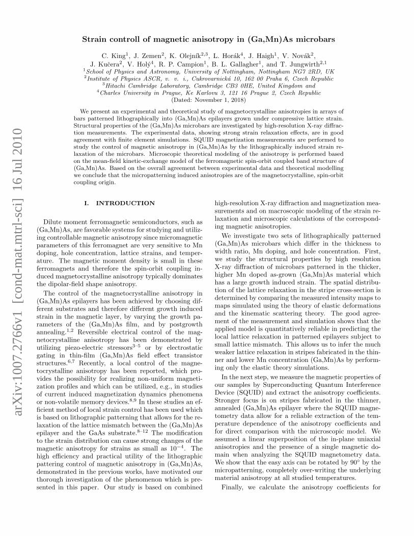
FIG. 2: (Color online) The measured (upper left panel) andsimulated (upper right panel) reciprocal-space maps in thesymmetric 004 diffraction of sample B[010]. In the bottomrow, the measured (points) and simulated (lines) intensitiesintegrated along the horizontal (left) and vertical (right) di-rections are plotted. In the intensity maps, the color scale islogarithmic.
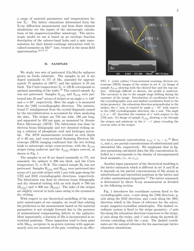
FIG. 3: (Color online) The measured (upper left panel) andsimulated (upper right panel) reciprocal-space maps in theasymmetric 404 diffraction of sample B[010]. In the bottomrow, the measured (points) and simulated (lines) intensitiesintegrated along the horizontal (left) and vertical (right) di-rections are plotted. In the intensity maps, the color scale islogarithmic.
Figs. 2 and 3 present examples of the measured (upperleft panels) and simulated (upper right panels) recipro-cal space maps, showing two maxima corresponding tothe reciprocal lattice points of the GaAs substrate andthe (Ga,Mn)As layer. The bottom panels show the mea-sured and simulated integrated intensities for two direc-tions in the reciprocal space. Since the lateral stripe pe-riod was larger than the coherence width of the primaryradiation, different stripes were irradiated incoherently,

4
so that the lateral intensity satellites stemming from thelateral stripe periodicity could not be resolved. The mea-sured intensity distribution is therefore proportional tothe intensity scattered from a single microbar.
We fitted the measured intensity maps to numericalsimulations based on the kinematic scattering theory andthe theory of anisotropic elastic medium. We used afinite-element simulation (implemented in Structural Me-chanics Module of Comsol Multiphysics, standard partialdifferential equation solver) to obtain the local relaxationdistribution ρ(x′, z′) in the stripes and derived the corre-sponding reciprocal space map. The angle of the sides ofthe stripes and the lattice mismatch e0 of the (Ga,Mn)Asand GaAs lattices were the two fitting parameters. Theleft column of Figs. 2 and 3 shows the measured diffrac-tion maps and projections. The right column shows thesimulated results. The lateral and vertical projectionsof the measured and simulated intensity maps as well asthe whole maps are used in the fitting. The coordinatesq′x and q′z span the reciprocal space conjugate to the realspace with coordinates x′ and z′ fixed to the stripe. Theyare measured with respect to the reciprocal lattice point004 and 404.
The remarkable agreement of the measured and simu-lated diffraction maps shows that our model of the latticedeformations is quantitatively relevant in determiningthe local lattice relaxation ρ(x′, z′) in the stripes shownin Fig. 4, the lattice mismatch between the epilayer andthe substrate, e0 = −0.38 ± 0.03% for set B, and thestripe geometry, a trapezoidal cross-section of the stripealso shown in Fig. 4. The largest relaxation is observedin the corners of the stripes.
The slopes of the sides in set B are few degrees largerthan angles typically occurring when dry etching is usedduring the patterning process. Note that the X-raydiffraction reveals only the regions with regular latticestructure whereas the dry etching can leave a thin non-uniform amorphous coating on the stripes which leads tothe unexpected non-rectilinear shape of the stripe cross-section resulting from the fitting.
In the next step, we use our modelling of the lattice re-laxation also for stripes of set A where the X-ray diffrac-tion would be less accurate due to the small volume ofthe epilayer, however, the relaxation mechanism shouldbe of the same nature as in set B. Fig. 5 shows the spa-tial dependence of the function ρ(x′, z′) for two differentgeometries relevant to samples in set A. The shape ofthe stripe cross-section cannot be determined from theSEM image of Fig. 1 with nanometer accuracy. Thisuncertainty cannot be neglected in the undercut stripesA[110]. Therefore, more geometries (slopes of the sides)were simulated and one representative example is givenin the upper panel of Fig. 5. On the other hand, theprecise shape of the sides does not play such an impor-tant role in case of the overcut stripes A[110] shown in the
lower panel of Fig. 5. In all geometries, the local inducedstrain is stronger closer to the edges of the stripes.
The comparison of the macroscopic simulations and X-
FIG. 4: (Color online) Finite element calculation of the lat-tice relaxation, ρ(x′, z′), on the cross-section perpendicularto the slightly overcut stripes B[110] (upper panel) and B[110]
(lower panel). The cross-section of one stripe and the under-lying substrate is plotted. The relaxation ρ = 1 and ρ = 0corresponds to a full relaxation of the lattice and to a latticeunder a compressive strain of the unpatterned layer, respec-tively. Both stripes are close to full relaxation.
FIG. 5: (Color online) Finite element calculation of the lat-tice relaxation, ρ(x′, z′), on the cross-section perpendicular tothe undercut stripes A[110] (upper panel) and overcut stripesA[110] (lower panel). The cross-section of one stripe and the
underlying substrate is plotted. The relaxation ρ = 1 andρ = 0 corresponds to full relaxation of the lattice and to alattice under a compressive strain of the unpatterned layer,respectively. All stripes show weaker net relaxation than thestripes in set B.
ray diffraction measurements are done on the level of thefull spatial distribution of the relaxation ρ(x′, z′). Themagnetic characteristics, considered in this work in thesingle domain approximation, are analyzed based on thenet lattice relaxation. Here we take advantage of the di-rect proportionality of the magnetocrystalline anisotropyto the corresponding strain18,19 and calculate the meananisotropy from the spatial average of ρ(x′, z′) over thestripe cross-section. We will denote this average quantityby ρ in the rest of the paper.
The last step in obtaining the input parameters for themicroscopic modelling is writing the net in-plane compo-

5
nents of the total strain tensor introduced in Eq. (1) inthe coordinate system fixed to the main crystallographicaxes introduced in Fig. 1:
exx = e0
(1 − ρ
2− ρ
2sin 2ω
), (2)
eyy = e0
(1 − ρ
2+ρ
2sin 2ω
),
exy = e0ρ
2cos 2ω,
where the angle ω is measured from the [110] axis andthe angle ω − 45 describes the rotation of the relax-ation direction (the dashed coordinates) with respect tothe crystalline coordinate system. Note that the abovestrain components coincide with those in Eq. (1) whenω = 45, i.e., the relaxation direction is aligned with the[100] axis. We emphasize that the average relaxation ρdepends on ω. We rotate the elasticity matrix describingthe cubic crystal when simulating the lattice relaxationalong different directions.
The strain components exx, eyy, and exy for the stripesin set A are obtained from the macroscopic simulationsand considering e0 ≈ −0.22%.16,20 Table I summarizes
e0[%] ρ
A[110] −0.22 ± 0.03 0.184 ± 0.005
A[110] −0.22 ± 0.03 0.24 ± 0.05
B[110] −0.38 ± 0.03 0.79 ± 0.01
B[010] −0.38 ± 0.03 0.99 ± 0.01
TABLE I: The lattice mismatch e0 and the lattice relaxationρ for the patterned samples as entering the microscopic cal-culations in Sec. V. The value of e0 in set B is determinedfrom the X-ray diffraction experiment, whereas e0 in set A isinferred from the partial Mn concentrations using the analysisof Refs. [20,16].
the parameters determined in this section.
IV. EXPERIMENTAL MAGNETICANISOTROPIES
In-plane magnetic anisotropies in thin (Ga,Mn)Asfilms are often analyzed using the lowest order decom-position of the free energy profile into separate terms ofdistinct symmetry.21–23 In this study, we follow this trackby adopting the following phenomenological formula:
F (ψ) = −Kc
4sin2 2ψ+Ku sin2 ψ−KΩ sin2(ψ−Ω). (3)
The cubic symmetry of the underlying zinc-blende struc-ture is described by the first term with minima along the[100] and [010] directions in case of Kc > 0. The sec-ond term quantified by the coefficient Ku describes theso called “intrinsic” uniaxial anisotropy along the crystal
FIG. 6: (Color online) Remanent magnetization along themain crystallographic directions for sample A0 (25 nm thickunpatterned epilayer).
diagonals present in the unpatterned (Ga,Mn)As epilay-ers. The last term quantified by KΩ describes the uniax-ial anisotropy with an extremum at an angle Ω inducedby the relaxation of the lattice mismatch of the dopedepilayer and the substrate. The angle Ω is in general notequal to the angle of the corresponding lattice relaxationω.19 Both angles are measured from the [110] axis.
A. Remanent magnetization
Remanent magnetization along the main crystallo-graphic directions was measured by SQUID for both setsof samples. The obtained values include the magneto-crystalline anisotropies described in the previous para-graph as well as the shape anisotropy which alwaysprefers the magnetization alignment with the longest sideof a rectangular prism such as the stripes.24
Fig. 6 shows that in the control sample A0 the intrinsicuniaxial anisotropy dominates over the cubic anisotropyon a large temperature range and the easy axis alongthe [110] diagonal. The ratio of the remanent magneti-zation projections to the [110] and [100] directions below60 K reveals that the system is almost purely uniaxial.The behavior of the anisotropy components at T > 60 Kcannot be described within the single domain approxima-tion. However, the anisotropies of unpatterned samplesare relevant to our microscopic analysis of measurementsin the microbars only at the lowest temperatures wherewe extract intrinsic anisotropy coefficients and deducethe material parameters as detailed in Sec. V.
Fig. 7 shows that the patterning of the sample A[110]
strengthens the uniaxial anisotropy present in the par-ent wafer. The [110] diagonal becomes the easiest of theinvestigated directions at all temperatures and the [110]diagonal becomes the hardest axis at all temperaturesbelow TC .
Fig. 8 shows that in the sample A[110], the two diago-

6
FIG. 7: (Color online) Remanent magnetization along themain crystallographic directions for sample A[110] (750 nm
wide stripes along the [110] direction).
FIG. 8: (Color online) Remanent magnetization along themain crystallographic directions for sample A[110] (750nmwide stripes along the [110] direction).
nals switch roles and in analogy with the previous casethe easy axis prefers alignment close to the stripe direc-tion, which is the hard axis over most of the temperaturerange in the parent wafer. This means that a rotationof the easy axis by as much as 90 is achieved by thepost-growth patterning. Note that the difference of theprojection of the remanent magnetization to the [100]and [010] directions in the two patterned samples is dueto a 5 misalignment between the stripes and the crystaldiagonals introduced during the fabrication.
The samples in set B posses stronger cubic anisotropy.Fig. 9 shows that in the control sample B0 the intrinsicuniaxial anisotropy dominates over the cubic anisotropyonly at temperatures above 20 K and the [110] diagonal iseasier than the [110] diagonal at all temperatures belowTC .
Fig. 10 shows a strengthening of the uniaxialanisotropy along the stripe direction in the sampleB[110], although not large enough to overcome the cubic
FIG. 9: (Color online) Remanent magnetization along themain crystallographic directions for sample B0 (200 nm thickunpatterned epilayer).
FIG. 10: (Color online) Remanent magnetization along themain crystallographic directions for sample B[110] (1 µm wide
stripes along the [110] direction).
anisotropy at the lowest temperatures. The transitionfrom cubic to uniaxial anisotropy occurs at a lower tem-perature than in the control sample. The [110] directionis hardened. The main crystal axes [100] and [010] re-main equal due to the more accurate alignment of thestripes with the crystal diagonal.
Fig. 11 shows a differentiation of the [100] and [010]projections in the sample B[010]. The uniaxial anisotropyalong the stripe direction now dominates at all tempera-tures. The intrinsic anisotropy differentiating the diago-nal directions is less pronounced than in case of B0 as ithas to compete also with the induced uniaxial anisotropy.
We can conclude that the universal effect seen in allpatterned (Ga,Mn)As/GaAs samples is the preferenceof the easy axis to align parallel to the stripe which

7
FIG. 11: (Color online) Remanent magnetization along themain crystallographic directions for sample B[010] (1 µm widestripes along the [010] direction).
is the direction in which the growth induced compres-sive strain cannot relax, i.e., the direction of the rel-ative lattice contraction in (Ga,Mn)As. This is remi-niscent of the magnetocrystalline anisotropy of unpat-terned (Ga,Mn)As epilayers which typically yields easy-axis oriented also along the direction of contraction, i.e.,in-plane for compressively strained (Ga,Mn)As epilayersand out-of-plane for (Ga,Mn)As films grown under ten-sile strain.19 We point out that the measured magnitudesof magnetic anisotropies in the microbars are an orderof magnitude larger than the shape anisotropy contribu-tion for given concentration of magnetic moments andthickness to width ratio. The microfabrication effectsin the (Ga,Mn)As stripes are therefore primarily dueto the spin-orbit coupling induced magnetocrystallineanisotropy.
B. Anisotropy coefficients
After investigating the reorientations of the easy axiswe focus on the magnitude of the individual anisotropycomponents. We measure the hysteresis loops using theSQUID magnetometry and fit the results to the followingequation:
F (ψ)/µ0 = −1
4MSHc sin2 2ψ +MSHu sin2 ψ − (4)
−MSHΩ sin2(ψ − Ω) −MSHcos(ψ − φH),
where Ki = µ0MSHi were introduced in Eq. (3), MS isthe saturation magnetization, H is the external magneticfield applied at the angle φH , and the last term is the Zee-man energy. All angles in Eq. (4) are measured from the[110] axis. In case of a general alignment of the induceduniaxial strain, the angle Ω of the corresponding uniaxialanisotropy is an independent fitting parameter. However,
in case of the main crystallographic axes and their smallsurrounding we can set Ω = ω, i.e., the anisotropy termis aligned with the corresponding uniaxial strain.19 Anoverview of the resulting angles Ω for the different align-ments of stripes in sets A and B is given in Table II.
Kc [kJ/m3] Ku [kJ/m3] KΩ [kJ/m3] Ω [deg]
A0 0.412 0.404 0.0
A[110] 0.412 0.404 0.83 95
A[110] 0.412 0.404 1.037 5
B0 2.213 0.381 0.0
B[110] 2.213 0.381 0.935 90
B[010] 2.213 0.381 0.696 45
TABLE II: The anisotropy coefficients obtained by fitting thehysteresis loops at T = 2 K to Eq. (4) and the angular shiftof the anisotropy term induced by the lattice relaxation asintroduced in Eq. (3). Note that the lattice relaxes perpen-dicular to the stripe direction. The error of the anisotropycoefficients is approximately 10 − 20%, approaching the up-per limit in case of the thick inhomogeneous samples in set B.
When determining the anisotropy coefficients in thestripes we use the assumption of linear superposition ofthe anisotropies present in the unpatterned samples withthe anisotropies induced by the patterning and latticerelaxation: the coefficients Kc and Ku are obtained firstin the control samples and kept fixed when fitting thestripes fabricated from the same epilayer. The assump-tion is justified on the qualitative level by the rema-nent magnetization measurement discussed in the pre-vious subsection which revealed the persistence of thebulk anisotropies in all patterned samples. Its valid-ity has been corroborated also by studies of epilayerssubject to post-growth piezo straining3 and lithographicpatterning.8 We emphasize that our approach is appro-priate only when the lattice relaxation direction is veryclose to the main crystallographic axes or when the angleΩ is also treated as a fitting paramater.19
Another assumption concerns the magnetization reori-entation mechanism determining the shape of the hys-teresis loops. In case of a dominant uniaxial anisotropywe fit the hysteresis loops obtained for external fields ap-plied along the hard axis. In case of a dominant cubicanisotropy there is no completely hard direction. Wenevertheless still consider a single domain model in thefitting.
Anisotropy coefficients for all six samples at the low-est temperature are summarized in Table II. Recall thatthese energies include also the contribution of the shapeanisotropy which amounts to ∼ 0.1 kJ/m3 in samplesA[110] and A[110] and ∼ 0.3 kJ/m3 in the samples B[110]
and B[010] with the higher thickness to width ratio. Notethat the smaller coefficient K45 leads to the formation ofa strongly uniaxial system as shown in Figs. 11, whereasthe larger coefficient K90 cannot overcome the cubicanisotropy component, at least at low temperatures as
8
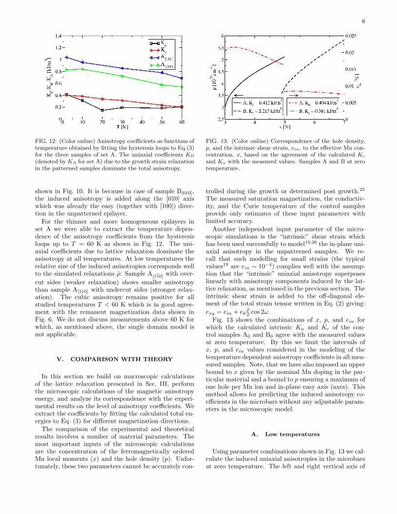
FIG. 12: (Color online) Anisotropy coefficients as functions oftemperature obtained by fitting the hysteresis loops to Eq.(3)for the three samples of set A. The uniaxial coefficients KΩ
(denoted by KA for set A) due to the growth strain relaxationin the patterned samples dominate the total anisotropy.
shown in Fig. 10. It is because in case of sample B[010],the induced anisotropy is added along the [010] axiswhich was already the easy (together with [100]) direc-tion in the unpatterned epilayer.
For the thinner and more homogeneous epilayers inset A we were able to extract the temperature depen-dence of the anisotropy coefficients from the hysteresisloops up to T = 60 K as shown in Fig. 12. The uni-axial coefficients due to lattice relaxation dominate theanisotropy at all temperatures. At low temperatures therelative size of the induced anisotropies corresponds wellto the simulated relaxations ρ: Sample A[110] with over-
cut sides (weaker relaxation) shows smaller anisotropythan sample A[110] with undercut sides (stronger relax-ation). The cubic anisotropy remains positive for allstudied temperatures T < 60 K which is in good agree-ment with the remanent magnetization data shown inFig. 6. We do not discuss measurements above 60 K forwhich, as mentioned above, the single domain model isnot applicable.
V. COMPARISON WITH THEORY
In this section we build on macroscopic calculationsof the lattice relaxation presented in Sec. III, performthe microscopic calculations of the magnetic anisotropyenergy, and analyze its correspondence with the experi-mental results on the level of anisotropy coefficients. Weextract the coefficients by fitting the calculated total en-ergies to Eq. (3) for different magnetization directions.
The comparison of the experimental and theoreticalresults involves a number of material parameters. Themost important inputs of the microscopic calculationsare the concentration of the ferromagnetically orderedMn local moments (x) and the hole density (p). Unfor-tunately, these two parameters cannot be accurately con-
FIG. 13: (Color online) Correspondence of the hole density,p, and the intrinsic shear strain, ein, to the effective Mn con-centration, x, based on the agreement of the calculated Kc
and Ku with the measured values. Samples A and B at zerotemperature.
trolled during the growth or determined post growth.25
The measured saturation magnetization, the conductiv-ity, and the Curie temperature of the control samplesprovide only estimates of these input parameters withlimited accuracy.
Another independent input parameter of the micro-scopic simulations is the “intrinsic” shear strain whichhas been used successfully to model19,26 the in-plane uni-axial anisotropy in the unpatterned samples. We re-call that such modelling for small strains (the typicalvalues19 are ein ∼ 10−4) complies well with the assump-tion that the “intrinsic” uniaxial anisotropy superposeslinearly with anisotropy components induced by the lat-tice relaxation, as mentioned in the previous section. Theintrinsic shear strain is added to the off-diagonal ele-ment of the total strain tensor written in Eq. (2) giving:
exy = ein + e0ρ2 cos 2ω.
Fig. 13 shows the combinations of x, p, and ein forwhich the calculated intrinsic Ku and Kc of the con-trol samples A0 and B0 agree with the measured valuesat zero temperature. By this we limit the intervals ofx, p, and ein values considered in the modeling of thetemperature dependent anisotropy coefficients in all mea-sured samples. Note, that we have also imposed an upperbound to x given by the nominal Mn doping in the par-ticular material and a bound to p ensuring a maximum ofone hole per Mn ion and in-plane easy axis (axes). Thismethod allows for predicting the induced anisotropy co-efficients in the microbars without any adjustable param-eters in the microscopic model.
A. Low temperatures
Using parameter combinations shown in Fig. 13 we cal-culate the induced uniaxial anisotropies in the microbarsat zero temperature. The left and right vertical axis of
9
3 4 5 6 7x [%]
0
0.1
0.2
0.3
0.4
0.5
0.6
0.7
0.8
0.9
1
KA
[kJ
/m3 ]
A[110]
, e0 = -0.22%, ^ = 0.239
A[-110]
, e0 = -0.22%, ^ = 0.184
0
1
2
3
4
5
6
7
8
9
10
KB [
kJ/m
3 ]
B[-110]
, e0 = -0.38%, ^ = 0.79
B[010]
, e0 = -0.38%, ^ = 0.999
ρ
ρ
ρ
ρ
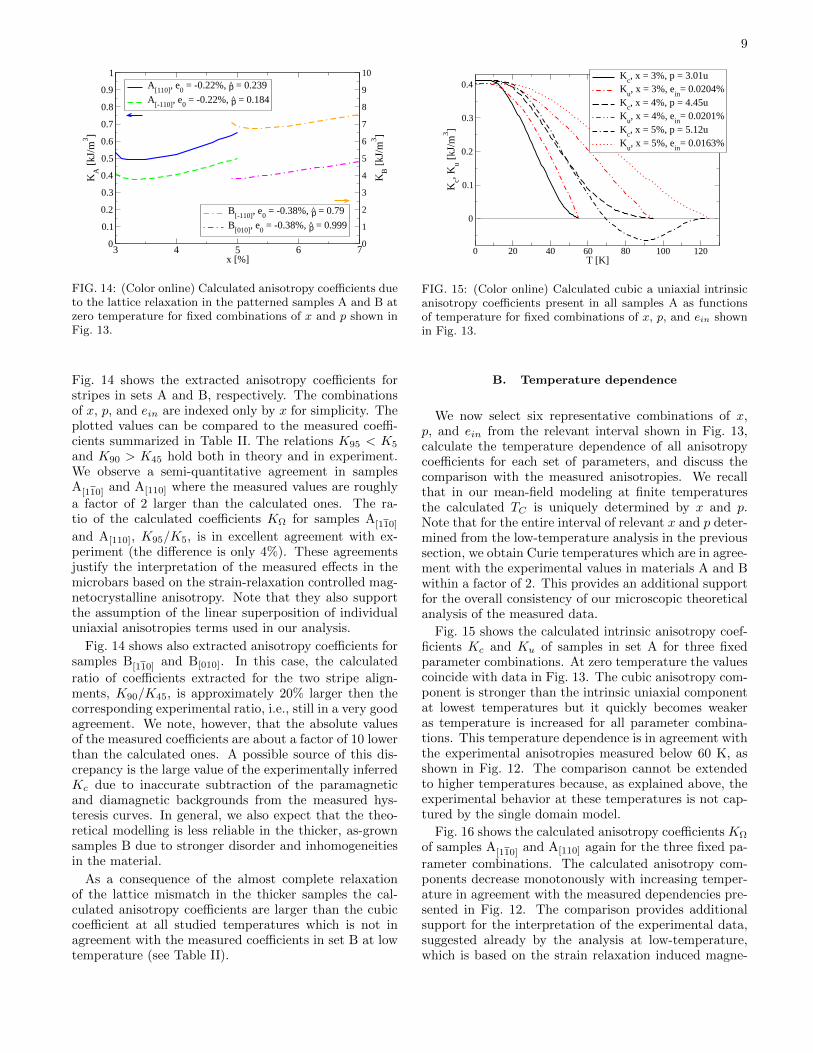
FIG. 14: (Color online) Calculated anisotropy coefficients dueto the lattice relaxation in the patterned samples A and B atzero temperature for fixed combinations of x and p shown inFig. 13.
Fig. 14 shows the extracted anisotropy coefficients forstripes in sets A and B, respectively. The combinationsof x, p, and ein are indexed only by x for simplicity. Theplotted values can be compared to the measured coeffi-cients summarized in Table II. The relations K95 < K5
and K90 > K45 hold both in theory and in experiment.We observe a semi-quantitative agreement in samplesA[110] and A[110] where the measured values are roughly
a factor of 2 larger than the calculated ones. The ra-tio of the calculated coefficients KΩ for samples A[110]
and A[110], K95/K5, is in excellent agreement with ex-periment (the difference is only 4%). These agreementsjustify the interpretation of the measured effects in themicrobars based on the strain-relaxation controlled mag-netocrystalline anisotropy. Note that they also supportthe assumption of the linear superposition of individualuniaxial anisotropies terms used in our analysis.
Fig. 14 shows also extracted anisotropy coefficients forsamples B[110] and B[010]. In this case, the calculated
ratio of coefficients extracted for the two stripe align-ments, K90/K45, is approximately 20% larger then thecorresponding experimental ratio, i.e., still in a very goodagreement. We note, however, that the absolute valuesof the measured coefficients are about a factor of 10 lowerthan the calculated ones. A possible source of this dis-crepancy is the large value of the experimentally inferredKc due to inaccurate subtraction of the paramagneticand diamagnetic backgrounds from the measured hys-teresis curves. In general, we also expect that the theo-retical modelling is less reliable in the thicker, as-grownsamples B due to stronger disorder and inhomogeneitiesin the material.
As a consequence of the almost complete relaxationof the lattice mismatch in the thicker samples the cal-culated anisotropy coefficients are larger than the cubiccoefficient at all studied temperatures which is not inagreement with the measured coefficients in set B at lowtemperature (see Table II).
0 20 40 60 80 100 120T [K]
0
0.1
0.2
0.3
0.4
Kc, K
u [kJ
/m3 ]
Kc, x = 3%, p = 3.01u
Ku, x = 3%, e
in= 0.0204%
Kc, x = 4%, p = 4.45u
Ku, x = 4%, e
in= 0.0201%
Kc, x = 5%, p = 5.12u
Ku, x = 5%, e
in= 0.0163%
FIG. 15: (Color online) Calculated cubic a uniaxial intrinsicanisotropy coefficients present in all samples A as functionsof temperature for fixed combinations of x, p, and ein shownin Fig. 13.
B. Temperature dependence
We now select six representative combinations of x,p, and ein from the relevant interval shown in Fig. 13,calculate the temperature dependence of all anisotropycoefficients for each set of parameters, and discuss thecomparison with the measured anisotropies. We recallthat in our mean-field modeling at finite temperaturesthe calculated TC is uniquely determined by x and p.Note that for the entire interval of relevant x and p deter-mined from the low-temperature analysis in the previoussection, we obtain Curie temperatures which are in agree-ment with the experimental values in materials A and Bwithin a factor of 2. This provides an additional supportfor the overall consistency of our microscopic theoreticalanalysis of the measured data.
Fig. 15 shows the calculated intrinsic anisotropy coef-ficients Kc and Ku of samples in set A for three fixedparameter combinations. At zero temperature the valuescoincide with data in Fig. 13. The cubic anisotropy com-ponent is stronger than the intrinsic uniaxial componentat lowest temperatures but it quickly becomes weakeras temperature is increased for all parameter combina-tions. This temperature dependence is in agreement withthe experimental anisotropies measured below 60 K, asshown in Fig. 12. The comparison cannot be extendedto higher temperatures because, as explained above, theexperimental behavior at these temperatures is not cap-tured by the single domain model.
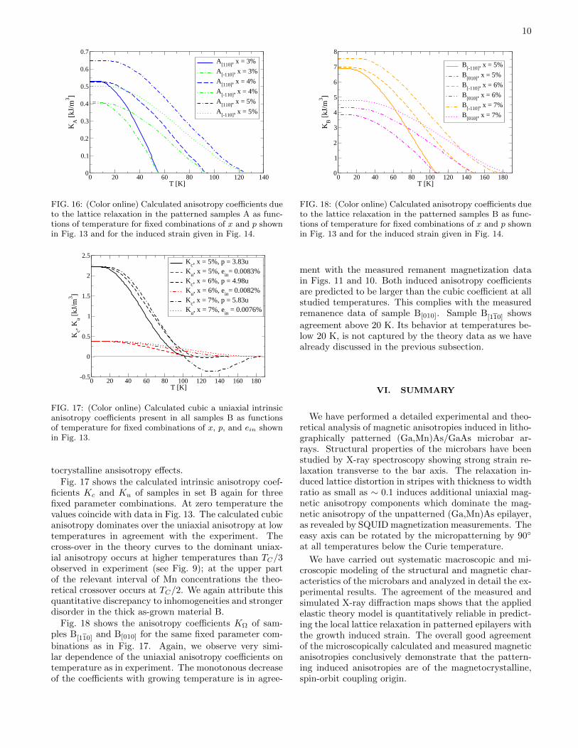
Fig. 16 shows the calculated anisotropy coefficients KΩ
of samples A[110] and A[110] again for the three fixed pa-
rameter combinations. The calculated anisotropy com-ponents decrease monotonously with increasing temper-ature in agreement with the measured dependencies pre-sented in Fig. 12. The comparison provides additionalsupport for the interpretation of the experimental data,suggested already by the analysis at low-temperature,which is based on the strain relaxation induced magne-
10
0 20 40 60 80 100 120 140T [K]
0
0.1
0.2
0.3
0.4
0.5
0.6
0.7
KA
[kJ
/m3 ]
A[110]
, x = 3%
A[-110]
, x = 3%
A[110]
, x = 4%
A[-110]
, x = 4%
A[110]
, x = 5%
A[-110]
, x = 5%
FIG. 16: (Color online) Calculated anisotropy coefficients dueto the lattice relaxation in the patterned samples A as func-tions of temperature for fixed combinations of x and p shownin Fig. 13 and for the induced strain given in Fig. 14.
0 20 40 60 80 100 120 140 160 180T [K]
-0.5
0
0.5
1
1.5
2
2.5
Kc, K
u [kJ
/m3 ]
Kc, x = 5%, p = 3.83u
Ku, x = 5%, e
in= 0.0083%
Kc, x = 6%, p = 4.98u
Ku, x = 6%, e
in= 0.0082%
Kc, x = 7%, p = 5.83u
Ku, x = 7%, e
in = 0.0076%
FIG. 17: (Color online) Calculated cubic a uniaxial intrinsicanisotropy coefficients present in all samples B as functionsof temperature for fixed combinations of x, p, and ein shownin Fig. 13.
tocrystalline ansisotropy effects.Fig. 17 shows the calculated intrinsic anisotropy coef-
ficients Kc and Ku of samples in set B again for threefixed parameter combinations. At zero temperature thevalues coincide with data in Fig. 13. The calculated cubicanisotropy dominates over the uniaxial anisotropy at lowtemperatures in agreement with the experiment. Thecross-over in the theory curves to the dominant uniax-ial anisotropy occurs at higher temperatures than TC/3observed in experiment (see Fig. 9); at the upper partof the relevant interval of Mn concentrations the theo-retical crossover occurs at TC/2. We again attribute thisquantitative discrepancy to inhomogeneities and strongerdisorder in the thick as-grown material B.
Fig. 18 shows the anisotropy coefficients KΩ of sam-ples B[110] and B[010] for the same fixed parameter com-
binations as in Fig. 17. Again, we observe very simi-lar dependence of the uniaxial anisotropy coefficients ontemperature as in experiment. The monotonous decreaseof the coefficients with growing temperature is in agree-
0 20 40 60 80 100 120 140 160 180T [K]
0
1
2
3
4
5
6
7
8
KB [
kJ/m
3 ]
B[-110]
, x = 5%
B[010]
, x = 5%
B[-110]
, x = 6%
B[010]
, x = 6%
B[-110]
, x = 7%
B[010]
, x = 7%
FIG. 18: (Color online) Calculated anisotropy coefficients dueto the lattice relaxation in the patterned samples B as func-tions of temperature for fixed combinations of x and p shownin Fig. 13 and for the induced strain given in Fig. 14.
ment with the measured remanent magnetization datain Figs. 11 and 10. Both induced anisotropy coefficientsare predicted to be larger than the cubic coefficient at allstudied temperatures. This complies with the measuredremanence data of sample B[010]. Sample B[110] shows
agreement above 20 K. Its behavior at temperatures be-low 20 K, is not captured by the theory data as we havealready discussed in the previous subsection.
VI. SUMMARY
We have performed a detailed experimental and theo-retical analysis of magnetic anisotropies induced in litho-graphically patterned (Ga,Mn)As/GaAs microbar ar-rays. Structural properties of the microbars have beenstudied by X-ray spectroscopy showing strong strain re-laxation transverse to the bar axis. The relaxation in-duced lattice distortion in stripes with thickness to widthratio as small as ∼ 0.1 induces additional uniaxial mag-netic anisotropy components which dominate the mag-netic anisotropy of the unpatterned (Ga,Mn)As epilayer,as revealed by SQUID magnetization measurements. Theeasy axis can be rotated by the micropatterning by 90
at all temperatures below the Curie temperature.
We have carried out systematic macroscopic and mi-croscopic modeling of the structural and magnetic char-acteristics of the microbars and analyzed in detail the ex-perimental results. The agreement of the measured andsimulated X-ray diffraction maps shows that the appliedelastic theory model is quantitatively reliable in predict-ing the local lattice relaxation in patterned epilayers withthe growth induced strain. The overall good agreementof the microscopically calculated and measured magneticanisotropies conclusively demonstrate that the pattern-ing induced anisotropies are of the magnetocrystalline,spin-orbit coupling origin.

11
Acknowledgments
We acknowledge fruitful discussions with A. W.Rushforth and K. Vyborny. The work was fundedthrough Præmium Academiæ and contracts number
AV0Z10100521, LC510, KAN400100652, FON/06/E002of GA CR, of the Czech republic, and by the NAMASTE(FP7 grant No. 214499) and SemiSpinNet projects (FP7grant No. 215368).
1 K. W. Edmonds, P. Boguslawski, K. Y. Wang, R. P. Cam-pion, N. R. S. Farley, B. L. Gallagher, C. T. Foxon, M. Saw-icki, T. Dietl, M. B. Nardelli, et al., Phys. Rev. Lett. 92,037201 (2004).
2 S. J. Potashnik, K. C. Ku, S. H. Chun, J. J. Berry,N. Samarth, and P. Schiffer, Appl. Phys. Lett. 79, 1495(2001).
3 A. W. Rushforth, E. D. Ranieri, J. Zemen, J. Wunderlich,K. W. Edmonds, C. S. King, E. Ahmad, R. P. Campion,C. T. Foxon, B. L. Gallagher, et al., Phys. Rev. B 78,085314 (2008), arXiv:0801.0886.
4 E. de Ranieri, A. W. Rushforth, K. Vyborny, U. Rana,E. Ahmad, R. P. Campion, C. T. Foxon, B. L. Gallagher,A. C. Irvine, J. Wunderlich, et al., New J. Phys. 10, 065003(2008), arXiv:0802.3344.
5 M. Overby, A. Chernyshov, L. P. Rokhinson, X. Liu,and J. K. Furdyna, Appl. Phys. Lett. 92, 192501 (2008),arXiv:0801.4191.
6 D. Chiba, M. Sawicki, Y. Nishitani, Y. Nakatani, F. Mat-sukura, and H. Ohno, Nature 455, 515 (2008).
7 M. H. S. Owen, J. Wunderlich, V. Novak, K. Olejnık,J. Zemen, K. Vyborny, S. Ogawa, A. C. Irvine, A. J.Ferguson, H. Sirringhaus, et al., New J. Phys. 11 (2009),arXiv:0807.0906.
8 J. Wunderlich, A. C. Irvine, J. Zemen, V. Holy, A. W.Rushforth, E. D. Ranieri, U. Rana, K. Vyborny, J. Sinova,C. T. Foxon, et al., Phys. Rev. B 76, 054424 (2007),arXiv:0707.3329.
9 K. Pappert, S. Humpfner, C. Gould, J. Wenisch, K. Brun-ner, G. Schmidt, and L. W. Molenkamp, Nature Phys. 3,573 (2007), arXiv:cond-mat/0701478.
10 J. Wenisch, C. Gould, L. Ebel, J. Storz, K. Pappert,M. J. Schmidt, C. Kumpf, G. Schmidt, K. Brunner, andL. W. Molenkamp, Phys. Rev. Lett. 99, 077201 (2007),arXiv:cond-mat/0701479.
11 S. Humpfner, M. Sawicki, K. Pappert, J. Wenisch,K. Brunner, C. Gould, G. Schmidt, T. Dietl, andL. W. Molenkamp, Appl. Phys. Lett. 90, 102102 (2007),arXiv:cond-mat/0612439.
12 A. W. Rushforth, K. Vyborny, C. S. King, K. W. Ed-monds, R. P. Campion, C. T. Foxon, J. Wunderlich, A. C.Irvine, P. Vasek, V. Novak, et al., Phys. Rev. Lett. 99,
147207 (2007), arXiv:cond-mat/0702357.13 T. Dietl, H. Ohno, and F. Matsukura, Phys. Rev. B 63,
195205 (2001), arXiv:cond-mat/0007190.14 M. Abolfath, T. Jungwirth, J. Brum, and A. H. Mac-
Donald, Phys. Rev. B 63, 054418 (2001), arXiv:cond-mat/0006093.
15 T. Jungwirth, J. Sinova, J. Masek, J. Kucera, and A. H.MacDonald, Rev. Mod. Phys. 78, 809 (2006), arXiv:cond-mat/0603380.
16 T. Jungwirth, K. Y. Wang, J. Masek, K. W. Edmonds,J. Konig, J. Sinova, M. Polini, N. A. Goncharuk, A. H.MacDonald, M. Sawicki, et al., Phys. Rev. B 72, 165204(2005), arXiv:cond-mat/0505215.
17 J. Masek, J. Kudrnovsky, and F. Maca, Phys. Rev. B 67,153203 (2003), arXiv:cond-mat/0302150.
18 J. Daeubler, S. Schwaiger, M. Glunk, M. Tabor,W. Schoch, R. Sauer, and W. Limmer, Physica p. 1876(2008).
19 J. Zemen, J. Kucera, K. Olejnik, and T. Jungwirth, Phys.Rev. B 80, 155203 (2009), arXiv:0904.0993.
20 L. X. Zhao, C. R. Staddon, K. Y. Wang, K. W. Edmonds,R. P. Campion, B. L. Gallagher, and C. T. Foxon, Appl.Phys. Lett. 86, 071902 (2005), arXiv:cond-mat/0501314.
21 X. Liu, W. L. Lim, L. V. Titova, M. Dobrowolska, J. K.Furdyna, M. Kutrowski, and T. Wojtowicz, J. Appl. Phys.98, 063904 (2005), arXiv:cond-mat/0505322.
22 U. Welp, V. K. Vlasko-Vlasov, X. Liu, J. K. Furdyna, andT. Wojtowicz, Phys. Rev. Lett. 90, 167206 (2003).
23 L. Thevenard, L. Largeau, O. Mauguin, A. Lemaıtre,K. Khazen, and H. J. von Bardeleben, Phys. Rev. B 75,195218 (2007), arXiv:cond-mat/0702548.
24 A. Aharoni, Journal of Applied Physics p. 3432 (1998).25 T. Jungwirth, J. Masek, K. Y. Wang, K. W. Edmonds,
M. Sawicki, M. Polini, J. Sinova, A. H. MacDonald, R. P.Campion, L. X. Zhao, et al., Phys. Rev. B 73, 165205(2005), arXiv:cond-mat/0508255.
26 M. Sawicki, K.-Y. Wang, K. W. Edmonds, R. P. Cam-pion, C. R. Staddon, N. R. S. Farley, C. T. Foxon, E. Pa-pis, E. Kaminska, A. Piotrowska, et al., Phys. Rev. B 71,121302 (2005), arXiv:cond-mat/0410544.


![Shree Kundkund-Kahan Parmarthik Trust file;saE w Utma H smta mn e, ko sa= ver mn e nih' (]I inymsar ga. 104 _pr pU. g uÌd evna wavvahI s uHdr Ývcnoma H=I. Aa ga=a _pr 5` vqt Ývcno](https://img.pdfslide.us/doc/110x75/5d2036b388c993ec448c990d/shree-kundkund-kahan-parmarthik-sae-w-utma-h-smta-mn-e-ko-sa-ver-mn-e-nih-i.jpg)
![DOI: 10.1038/NPHOTON.2013.76 Experimental observation of ...€¦ · (Ga,Mn)As [8]. The interpretation would imply sizable changes of magnetic anisotropy in materials with equilibrium](https://img.pdfslide.us/doc/110x75/5edaad2fea30a273770f453e/doi-101038nphoton201376-experimental-observation-of-gamnas-8-the.jpg)