Embed Size (px)
Citation preview

STOx’s 2012 TEAM DESCRIPTION
PAPER Saith Rodríguez, Eyberth Rojas, Katherin Pérez, Jorge Lopez,
Heyson Baez, Juan Manuel Calderón
Faculty of Electronical Engineering
Universidad Santo Tomás
Bogotá, Colombia
[email protected], [email protected], andreaher-
[email protected], [email protected], [email protected],
Abstract: This paper shows the state of Small Size League team of
Universidad Santo Tomas, it is on duty since RoboCup Turkey 2011
and it intends to participate in Mexico 2012. It describes the software
and hardware design emphasizing in the enhancements done over this
year.
1. INTRODUCTION STOx's SSL Team was built by G.E.D. (Study and design group of robotic), it is
associated to Electronic Engineering Faculty of Universidad Santo Tomas, in order to
join the global Robocup initiative. On 2010, it participated by first time in Latiname-
rican RoboCup Open held in Sao Paulo (Brazil) where it played the final versus Ro-
boFei team thus obtaining the second place. Subsequently on 2011 it participated by
first time at RoboCup World Championship held in Istanbul (Turkey), where it was
among the top twelve.
The hardware design is composed of mechanical devices and electronic control
systems that comprising the robot, within which are: traction control, dribbling and
kicker system. The software design is composed by filtering and prediction modules,
High level control and the artificial intelligent system that is responsible to take deci-
sions about team strategies.
This year, the main improves of our team are: the manufacturing of a new PCB, an
addition of torque control system and model of kinematics modified and the building
of new strategies with six agents.
2. HARDWARE DESIGN Our primary equipment consists of eight identical robots built on 2011. The me-
chanical design of these robots wasn’t significantly changed. The robot measures are
178 mm of diameter and 145 mm high. The driving system (dribbler) covers the ball
by 18%, according to the competition rules. The real robot and 3D model of robot are
shown at Fig. 1 and Fig. 2 respectively.

2.1 MECHANICS
Mechanical components are based on previous designs of teams of league, and our
team developed our own designs to accomplish the needs of the robots and game
requirements.
Fig. 1 Real robot Fig. 2. 3D Mechanical model of the
robot
Chassis: The chassis was built based on the design of Skuba 2009. All the pieces
were made with CNC machinery using aluminum 7075. The material used and fabri-
cation process provides to the robot a good balance between strength and weight, also
a high quality of parts.
Traction: The robot's traction is omni-directional, with four custom-built wheels.
Each wheel has 50mm diameter with 15 rollers, these wheels are attached to the mo-
tors through a gearbox of 61:17 based on Skuba design 2009. The robot has four
brushless motors “Maxon EC45- Flat 30W", these motors provide a maximum speed
of 3.2 m/s to each robot. This year we incorporate double seal o’rings to the rollers to
provide a better grip to wheels. The Robot's chassis with wheels and motors is shown
in Fig. 3.
Fig. 3 Robot's chassis with wheels and motors

Dribbler: The ball dribbling system is essentially composed by
less motor mated to a cylindrical rod covered by
set provides a maximum rotation speed of 12000 rpms, also the design f
shioning system to make more effective
bling system and the Fig.5 shows the model of dribbling system.
Fig. 4 Dribbling System
Flat Kicker: The main kicker device is a custom solenoid. The core is made of
Bakelite, wrapped with 6 layers (400 turns approx) of 24AWG enameled wire. The
plunger is composed by two parts, a highly magnetic one and other non
This configuration provides to
limited to 8m/s by software to respect current rules.
Chip Kicker: The parabolic kick system is based on SKUBA design and provides
a 4m of ball kick distance. It uses a
2.2 ELECTRONICS
Last year each robot used a SPARTAN 3 Starter Kit, for this year we are develo
ing a custom board in order to optimize the
ball dribbling system is essentially composed by an EC-22 brus
to a cylindrical rod covered by rubber with 10mm of diameters. This
imum rotation speed of 12000 rpms, also the design features a c
m to make more effective the ball dribbling. The Fig. 4 shows the dri
bling system and the Fig.5 shows the model of dribbling system.
Dribbling System Fig. 5 Model of the dribbling sy
tem
The main kicker device is a custom solenoid. The core is made of
Bakelite, wrapped with 6 layers (400 turns approx) of 24AWG enameled wire. The
plunger is composed by two parts, a highly magnetic one and other non- magnetic.
This configuration provides to robot a maximum kick speed of 10m/s. The speed was
limited to 8m/s by software to respect current rules.
Fig. 6. Flat Kicker
The parabolic kick system is based on SKUBA design and provides
a 4m of ball kick distance. It uses a different solenoid that the main kicker.
ELECTRONICS
Last year each robot used a SPARTAN 3 Starter Kit, for this year we are develo
in order to optimize the space inside the robot.
22 brush-
rubber with 10mm of diameters. This
eatures a cu-
. The Fig. 4 shows the drib-
Model of the dribbling sys-
The main kicker device is a custom solenoid. The core is made of
Bakelite, wrapped with 6 layers (400 turns approx) of 24AWG enameled wire. The
magnetic.
robot a maximum kick speed of 10m/s. The speed was
The parabolic kick system is based on SKUBA design and provides
Last year each robot used a SPARTAN 3 Starter Kit, for this year we are develop-

The robot’s electronic system consists of two
implemented on a Spartan3 XC3S400
that performs a coupling of control logic signals to the motors and sensors.
Traction motors control
It consists in a torque
mented by a quadrature encoder 300 PPR. The brushless motor driver consists of a
simple combinational circuit that switches the three
the Hall Effect motor sensors. In order to regulate
signal, which is operated by a
outputs.
The PI controller is implemented on
Embedded Processor Development Kit.
Dribbler Motor Control
fundamental difference is that it doesn't use an encoder to measure the speed but uses
motor’s Hall Effect sensor signals for this purpose. This modification was done b
cause the dribbler control doesn't require a high performance driver. Add
was implemented an over
phases Bridge when the motor i
Kicker’s Circuit: This circuit consists of two elementary parts: A DC boost co
verter circuit which charges
The second part of this design is the two IGBTs which drives energy from capacitors
to corresponding solenoids. The IGBT control signal is a PWM signal that allows the
shot intensity modulation.
Ball’s Sensor: This sensor is an IR emitter
ence inside the robot’s Dribbler. The sensor signal is amplified and digitized to be
analyzed by the AI system.
Communication: For this purpose we use X
duplex communication between the robots and the central system. The X
ules operate in broadcast mode at 2.4GHz frequency and can be set up in 8 different
The robot’s electronic system consists of two components: first, the logical system
implemented on a Spartan3 XC3S400-PQ144 FPGA and second, the power system
that performs a coupling of control logic signals to the motors and sensors.
Traction motors control:
torque PI controller manually tuned. The speed sensor is impl
mented by a quadrature encoder 300 PPR. The brushless motor driver consists of a
simple combinational circuit that switches the three-phases according to the state of
sensors. In order to regulate the motor’s speed we use a PWM
signal, which is operated by a logical AND with each one of brushless motor driver
The PI controller is implemented on Microblaze Embedded Processor wit
Embedded Processor Development Kit.
Fig. 7 Control system of traction motors
Dribbler Motor Control: This system is similar to shown in Figure 7 (above). The
fundamental difference is that it doesn't use an encoder to measure the speed but uses
motor’s Hall Effect sensor signals for this purpose. This modification was done b
cause the dribbler control doesn't require a high performance driver. Additionally, it
was implemented an over-current protection circuit avoiding the damage of the three
phases Bridge when the motor it’s being blocked.
This circuit consists of two elementary parts: A DC boost co
verter circuit which charges two capacitors of 2700µF from 0 to 200V in 10 seconds.
The second part of this design is the two IGBTs which drives energy from capacitors
to corresponding solenoids. The IGBT control signal is a PWM signal that allows the
shot intensity modulation.
This sensor is an IR emitter-receiver pair that detects the ball pre
ence inside the robot’s Dribbler. The sensor signal is amplified and digitized to be
analyzed by the AI system.
For this purpose we use X-Bee modules, which provi
duplex communication between the robots and the central system. The X-Bee mo
ules operate in broadcast mode at 2.4GHz frequency and can be set up in 8 different
components: first, the logical system
PQ144 FPGA and second, the power system
ally tuned. The speed sensor is imple-
mented by a quadrature encoder 300 PPR. The brushless motor driver consists of a
phases according to the state of
the motor’s speed we use a PWM
brushless motor driver
ith Xilinx
(above). The
fundamental difference is that it doesn't use an encoder to measure the speed but uses
motor’s Hall Effect sensor signals for this purpose. This modification was done be-
itionally, it
current protection circuit avoiding the damage of the three-
This circuit consists of two elementary parts: A DC boost con-
two capacitors of 2700µF from 0 to 200V in 10 seconds.
The second part of this design is the two IGBTs which drives energy from capacitors
to corresponding solenoids. The IGBT control signal is a PWM signal that allows the
receiver pair that detects the ball pres-
ence inside the robot’s Dribbler. The sensor signal is amplified and digitized to be
Bee modules, which provide full-
Bee mod-
ules operate in broadcast mode at 2.4GHz frequency and can be set up in 8 different

channels. Our team usually used channel 4, but it can be set up quickly into another
channel.
Power Supply: This is a single Li
of 2000mAh which provides to the robot with 30 minutes of play autonomy
3. SOFTWARE DESIGN
The STOx´s software was developed on Microsoft Visual Studio 2008 and cons
of different parts like filtering, prediction, control modules and also a multi
artificial intelligent system. The syste
Vision Server: This block receives the data from
Socket, this data joins the information provided by both cameras and it organizes data
depending of team color
Vision Module: In order to compensate the latency of system, the ball position
and each robot location are predicted b
tracking with the purpose to increase the reliability of ball position into game field.
Strategy Module: In this section we describe all about Team’s intelligence. The
decisions are taken depending on the dif
the RefereeBox. The general architecture has a hierarchy form. The vision data and
RefereeBox information are evaluated in a module enabled for the team’s strategy,
which gives the roles (game attitudes) to ea
game’s situations. The block
channels. Our team usually used channel 4, but it can be set up quickly into another
This is a single Li-Po battery; it is 11.1 volts and nominal capacity
of 2000mAh which provides to the robot with 30 minutes of play autonomy.
SOFTWARE DESIGN
The STOx´s software was developed on Microsoft Visual Studio 2008 and cons
of different parts like filtering, prediction, control modules and also a multi
artificial intelligent system. The system architecture is shown in Fig. 8.
Fig. 8 Software architecture
This block receives the data from SSL-Vision through a UDP
Socket, this data joins the information provided by both cameras and it organizes data
depending of team color.
In order to compensate the latency of system, the ball position
and each robot location are predicted by using Kalman filters, also it performs a ball
tracking with the purpose to increase the reliability of ball position into game field.
: In this section we describe all about Team’s intelligence. The
decisions are taken depending on the different game situations and the orders given by
the RefereeBox. The general architecture has a hierarchy form. The vision data and
RefereeBox information are evaluated in a module enabled for the team’s strategy,
which gives the roles (game attitudes) to each one of the robotic agents according to
game’s situations. The block diagram it’s shown in the Fig.9.
channels. Our team usually used channel 4, but it can be set up quickly into another
Po battery; it is 11.1 volts and nominal capacity
The STOx´s software was developed on Microsoft Visual Studio 2008 and consists
of different parts like filtering, prediction, control modules and also a multi-agent
Vision through a UDP
Socket, this data joins the information provided by both cameras and it organizes data
In order to compensate the latency of system, the ball position
y using Kalman filters, also it performs a ball
tracking with the purpose to increase the reliability of ball position into game field.
: In this section we describe all about Team’s intelligence. The
ferent game situations and the orders given by
the RefereeBox. The general architecture has a hierarchy form. The vision data and
RefereeBox information are evaluated in a module enabled for the team’s strategy,
ch one of the robotic agents according to

Control Module: It consists of two parts: an algorithm of path planning which ca
culates the robot motion path to reach a goal avoiding obstacles and the Bang Bang
algorithm that controls the robot´s velocity changes into the game field.
X-Bee Server: It is responsible fo
monitoring each robot.
GUI: It is a Dialog Box which
tem in order to detect mistakes and monitoring processes, also permit to adjust online
setup.
Simulator: The team uses the simulator supplied by Parsian Robotic
4. CONCLUSIONS AND RESULTSThis Project began in 2009 and so far we have the same team who participated on
the Latin American Robocup Open 2010 taking the second place.
The design and development of these robots has allowed students involve in this
initiative. Students can learn how to program every system that can be found in each
robot, and also the general artificial intelligence, the
required for development of each one of the platforms.
Since 2009 we have faced different problems and challenges of build these robots,
but with the help and useful information found in the ETDPs, We could solve many
problems and create a platform accordin
League. We hope to take a pa
experience with teams around the world.
Fig. 9. Strategy Module
It consists of two parts: an algorithm of path planning which ca
culates the robot motion path to reach a goal avoiding obstacles and the Bang Bang
algorithm that controls the robot´s velocity changes into the game field.
It is responsible for sending and receiving control commands and
It is a Dialog Box which displays the most important information of the sy
tem in order to detect mistakes and monitoring processes, also permit to adjust online
he team uses the simulator supplied by Parsian Robotics.
CONCLUSIONS AND RESULTS This Project began in 2009 and so far we have the same team who participated on
the Latin American Robocup Open 2010 taking the second place.
The design and development of these robots has allowed students involve in this
. Students can learn how to program every system that can be found in each
robot, and also the general artificial intelligence, the electronic and mechanical design
equired for development of each one of the platforms.
Since 2009 we have faced different problems and challenges of build these robots,
but with the help and useful information found in the ETDPs, We could solve many
problems and create a platform according to the requirements for the RoboCup F180
League. We hope to take a part this year at the RoboCup 2012 and can share all our
experience with teams around the world.
It consists of two parts: an algorithm of path planning which cal-
culates the robot motion path to reach a goal avoiding obstacles and the Bang Bang
r sending and receiving control commands and
most important information of the sys-
tem in order to detect mistakes and monitoring processes, also permit to adjust online
This Project began in 2009 and so far we have the same team who participated on
The design and development of these robots has allowed students involve in this
. Students can learn how to program every system that can be found in each
and mechanical design
Since 2009 we have faced different problems and challenges of build these robots,
but with the help and useful information found in the ETDPs, We could solve many
g to the requirements for the RoboCup F180
and can share all our
REFERENCES1. Skuba 2011 Extended
bremen.de/tdp/etdp2011/SKUBA_ETDP_2011.pdf
2. Skuba 2010 Extended Team Description.
bremen.de/tdp/etdp2010/skuba.pdf
3. Skuba 2009 Extended Team Description. http://small
bremen.de/tdp/etdp2009/small_skuba.pdf
4. Fosler, R.: Generating
chip Technology Inc. (2005)
5. Bruce, J., Veloso, M.: Real
ceedings of the IEEE Conference on Intelligent Robots and Systems. (2002)
6. Valiallah Monajjemi, Ali Koochakzadeh, Saeed Shiry Ghidary, “grSim
Size Robot Soccer Simulator”, to appear in :
2011
7. RUSSELL, N. Inteligencia Artificial: Un Enfoque Moderno.
8. Gary Bishop, An Introduction to the Kalman Filter: University of North Carolina at Ch
pel Hill
Fig 10. STOx’s team
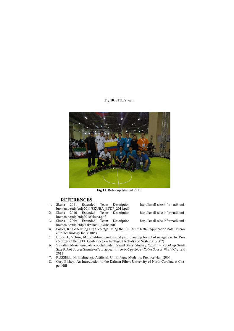
Fig 11. Robocup Istanbul 2011.
REFERENCES Extended Team Description. http://small-size.informatik.uni
bremen.de/tdp/etdp2011/SKUBA_ETDP_2011.pdf
Skuba 2010 Extended Team Description. http://small-size.informatik.uni
bremen.de/tdp/etdp2010/skuba.pdf
Skuba 2009 Extended Team Description. http://small-size.informatik.uni
bremen.de/tdp/etdp2009/small_skuba.pdf
Fosler, R.: Generating High Voltage Using the PIC16C781/782. Application note, Micr
chip Technology Inc. (2005)
Bruce, J., Veloso, M.: Real-time randomized path planning for robot navigation. In: Pr
ceedings of the IEEE Conference on Intelligent Robots and Systems. (2002)
llah Monajjemi, Ali Koochakzadeh, Saeed Shiry Ghidary, “grSim – RoboCup Small
Size Robot Soccer Simulator”, to appear in : RoboCup 2011: Robot Soccer World Cup XV
RUSSELL, N. Inteligencia Artificial: Un Enfoque Moderno. Prentice Hall, 2004.
Bishop, An Introduction to the Kalman Filter: University of North Carolina at Ch
size.informatik.uni-
size.informatik.uni-
size.informatik.uni-
High Voltage Using the PIC16C781/782. Application note, Micro-
time randomized path planning for robot navigation. In: Pro-
RoboCup Small
RoboCup 2011: Robot Soccer World Cup XV,
Prentice Hall, 2004.
Bishop, An Introduction to the Kalman Filter: University of North Carolina at Cha-

9. C. H. Messom, G. Sen Gupta, S. Demidenko and Lim Yuen Siong. : Improving Predictive
Control of a Mobile Robot: Application of Image Processing and Kalman Filtering: IMTC
2003 –Instrumentation and Measurement: 20-22 May 2003
10. Erik Cuevas, Daniel Zaldivar and Raul Rojas: Kalman filter for vision tracking: Technical
Report: 10th August 2005
11. Xilinx EDK Concepts, Tools and Techniques: A Hands-On Guide to Effective Embedded
System Design: EDK 13.1: UG683 April 13, 2011