Embed Size (px)
Citation preview
9/4/2014
Stormwater Management Guide For
Private Driveways and Roads
These practices are necessary to satisfy the water quantity and water quality criteria of the Virginia Stormwater Management Program (VSMP) Construction General Permit (9VAC25-880). These practices maintain dispersed flows and prevent environmental damage due to erosion and increased runoff from development. These practices may be used for in-lieu-of agreements or residential site plan submissions.
The practices listed here are not comprehensive, and alternative practices may be
appropriate for the site. Consult the U.S. Forest Service Environmentally Sensitive Road Maintenance Practices for Dirt and Gravel Roads http://www.fs.fed.us/t-d/pubs/pdf/11771802.pdf
And Consult the Center for Dirt and Gravel Road Studies, Penn State University
http://www.dirtandgravel.psu.edu/
1 | P a g e

9/4/2014
Figure 2: Typical Driveway Layout
Driveway practices: 2.1 Road Surface Shaping 2.2 Dips 2.3 Belt Diversion 2.4 Geotextile Separation 2.5 Roadside Ditch 2.6 Grass Channel 2.7 Ditch Turnout 2.8 Engineered Level Spreaders 2.9 Cross Culvert 2.10 French Mattress 2.11 Clearwater Crossing 2.12 Ford and Culvert Crossings
2 | P a g e
9/4/2014
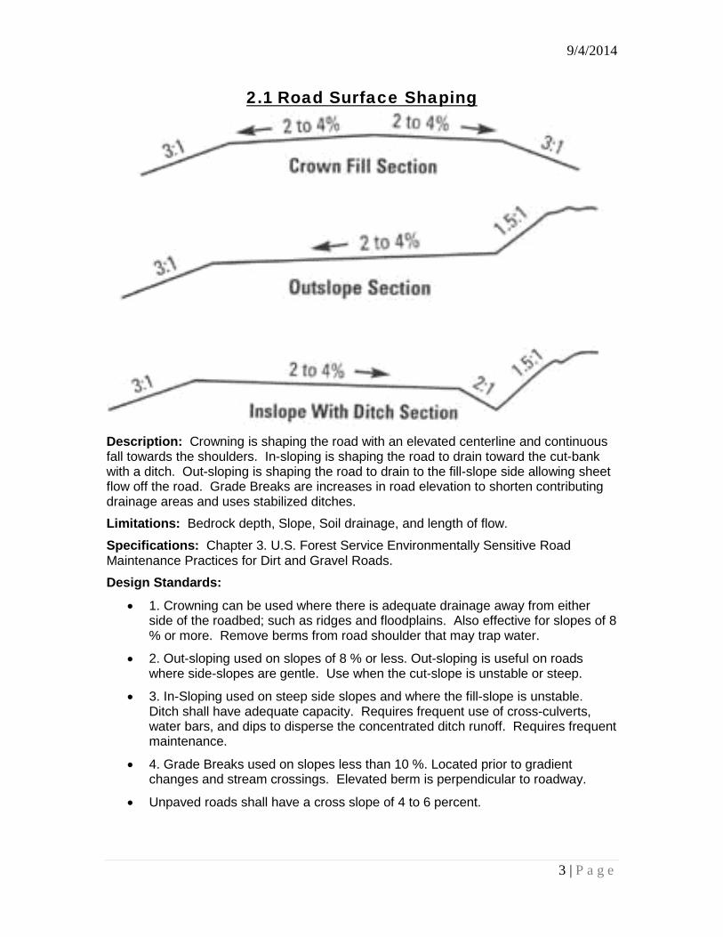
2.1 Road Surface Shaping
Description: Crowning is shaping the road with an elevated centerline and continuous fall towards the shoulders. In-sloping is shaping the road to drain toward the cut-bank with a ditch. Out-sloping is shaping the road to drain to the fill-slope side allowing sheet flow off the road. Grade Breaks are increases in road elevation to shorten contributing drainage areas and uses stabilized ditches.
Limitations: Bedrock depth, Slope, Soil drainage, and length of flow.
Specifications: Chapter 3. U.S. Forest Service Environmentally Sensitive Road Maintenance Practices for Dirt and Gravel Roads.
Design Standards:
• 1. Crowning can be used where there is adequate drainage away from either side of the roadbed; such as ridges and floodplains. Also effective for slopes of 8 % or more. Remove berms from road shoulder that may trap water.
• 2. Out-sloping used on slopes of 8 % or less. Out-sloping is useful on roads where side-slopes are gentle. Use when the cut-slope is unstable or steep.
• 3. In-Sloping used on steep side slopes and where the fill-slope is unstable. Ditch shall have adequate capacity. Requires frequent use of cross-culverts, water bars, and dips to disperse the concentrated ditch runoff. Requires frequent maintenance.
• 4. Grade Breaks used on slopes less than 10 %. Located prior to gradient changes and stream crossings. Elevated berm is perpendicular to roadway.
• Unpaved roads shall have a cross slope of 4 to 6 percent.
3 | P a g e

9/4/2014
2.2 Dips
Description: Dips are designed and constructed to divert water off the road surface, disperse surface water flows, and reduce erosion. The road profile (vertical alignment) is changed by simultaneously constructing a dip and raising the grade by placing fill material in the road below the dip. The slightly skewed dip turns surface flows and disperses runoff away from the road surface. Limitations: Bedrock depth, slope of outfall, and traffic. Specifications: Chapter 3. U.S. Forest Service Environmentally Sensitive Road Maintenance Practices for Dirt and Gravel Roads; VESCH 3.11 and 3.18 Design Standards:
• Maximum slope of road shall be 10 percent.
• Depth, B of the dip shall be 8 inches.
• Approaching length, L3 shall be between 10 and 25 feet
• May be used to replace or supplement a cross-culvert
• Not to be used to divert spring or stream flows.
• Angle the dip across the road in the direction of flow between 20 and 40 degrees. Slope the dip 3 percent across the bottom toward the outlet.
• The berm shall have a reverse grade between 2 and 8 percent.
• The outlet shall be stabilized with a stone apron in accordance with VESCH 3.18.
• If multiple Dips are needed they shall be spaced; as measured from the toe of the berm, in accordance with the following equation: X = (0.68S + 1) (100/S); where S is the road slope in percent (%)
4 | P a g e
9/4/2014
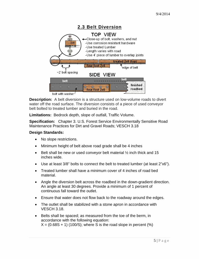
2.3 Belt Diversion
Description: A belt diversion is a structure used on low-volume roads to divert water off the road surface. The diversion consists of a piece of used conveyor belt bolted to treated lumber and buried in the road. Limitations: Bedrock depth, slope of outfall, Traffic Volume. Specification: Chapter 3. U.S. Forest Service Environmentally Sensitive Road Maintenance Practices for Dirt and Gravel Roads; VESCH 3.18 Design Standards:
• No slope restrictions.
• Minimum height of belt above road grade shall be 4 inches
• Belt shall be new or used conveyor belt material ½ inch thick and 15 inches wide.
• Use at least 3/8” bolts to connect the belt to treated lumber (at least 2”x6”).
• Treated lumber shall have a minimum cover of 4 inches of road bed material.
• Angle the diversion belt across the roadbed in the down-gradient direction. An angle at least 30 degrees. Provide a minimum of 1 percent of continuous fall toward the outlet.
• Ensure that water does not flow back to the roadway around the edges.
• The outlet shall be stabilized with a stone apron in accordance with VESCH 3.18.
• Belts shall be spaced; as measured from the toe of the berm, in accordance with the following equation: X = (0.68S + 1) (100/S); where S is the road slope in percent (%)
5 | P a g e
9/4/2014
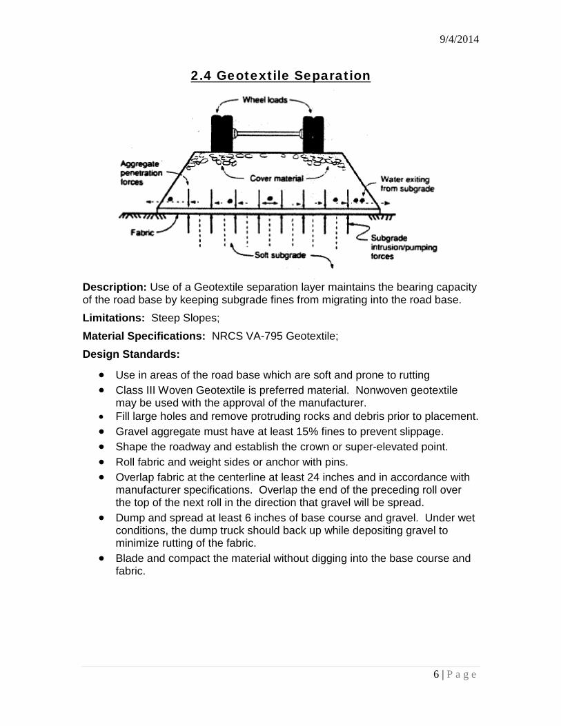
2.4 Geotextile Separation
Description: Use of a Geotextile separation layer maintains the bearing capacity of the road base by keeping subgrade fines from migrating into the road base. Limitations: Steep Slopes; Material Specifications: NRCS VA-795 Geotextile; Design Standards:
• Use in areas of the road base which are soft and prone to rutting • Class III Woven Geotextile is preferred material. Nonwoven geotextile
may be used with the approval of the manufacturer. • Fill large holes and remove protruding rocks and debris prior to placement. • Gravel aggregate must have at least 15% fines to prevent slippage. • Shape the roadway and establish the crown or super-elevated point. • Roll fabric and weight sides or anchor with pins. • Overlap fabric at the centerline at least 24 inches and in accordance with
manufacturer specifications. Overlap the end of the preceding roll over the top of the next roll in the direction that gravel will be spread.
• Dump and spread at least 6 inches of base course and gravel. Under wet conditions, the dump truck should back up while depositing gravel to minimize rutting of the fabric.
• Blade and compact the material without digging into the base course and fabric.
6 | P a g e
9/4/2014
2.5 Roadside Ditches
Description: Collects and carry runoff, seeps and springs to designated discharge locations. Limitations: Steep Slopes; Setbacks; Side Slopes Material Specifications: VESCH 3.17, 3.19, 3.20, 3.32, and 3.36 Design Standards:
• Ditches should only be used when one the following conditions exist: o Runoff, seepage or spring water is expressed in the cut-bank needs
to be diverted away from the road surface; o In-sloping on roads traversing steep side slopes; and o Road is super-elevated to accommodate higher speeds and traffic
• Minimize the length of the ditch run and the contributing drainage area.
• A parabolic or trapezoidal ditch is preferred.
• Side slopes shall be 2:1 or flatter. Steeper side slopes will be allowed if an appropriate lining material is used (i.e. rip rap or concrete).
• Must discharge to a well-vegetated area that has a slope less than 15 percent. A gravel diaphragm, rip rap apron or engineered level spreader may be needed at the outlet.
• Slopes less than 2 percent should be seeded and mulched in accordance with VESCH 3.32 and 3.30. Slopes greater than 2 percent shall be seeded and stabilized with temporary matting in accordance with VESCH 3.36.
• Slopes greater than 10 percent shall minimize ditch length or stabilize with rip rap in accordance with VESCH 3.19.
• The channel shall have the capacity to carrying the 10-year design storm. Requires a minimum of 6 inches of freeboard when the channel follows a roadway.
• The channel shall have a 2-year flow velocity that is non-erosive.
7 | P a g e
9/4/2014
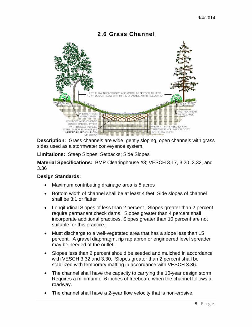
2.6 Grass Channel
Description: Grass channels are wide, gently sloping, open channels with grass sides used as a stormwater conveyance system. Limitations: Steep Slopes; Setbacks; Side Slopes Material Specifications: BMP Clearinghouse #3; VESCH 3.17, 3.20, 3.32, and 3.36 Design Standards:
• Maximum contributing drainage area is 5 acres
• Bottom width of channel shall be at least 4 feet. Side slopes of channel shall be 3:1 or flatter
• Longitudinal Slopes of less than 2 percent. Slopes greater than 2 percent require permanent check dams. Slopes greater than 4 percent shall incorporate additional practices. Slopes greater than 10 percent are not suitable for this practice.
• Must discharge to a well-vegetated area that has a slope less than 15 percent. A gravel diaphragm, rip rap apron or engineered level spreader may be needed at the outlet.
• Slopes less than 2 percent should be seeded and mulched in accordance with VESCH 3.32 and 3.30. Slopes greater than 2 percent shall be stabilized with temporary matting in accordance with VESCH 3.36.
• The channel shall have the capacity to carrying the 10-year design storm. Requires a minimum of 6 inches of freeboard when the channel follows a roadway.
• The channel shall have a 2-year flow velocity that is non-erosive.
8 | P a g e
9/4/2014
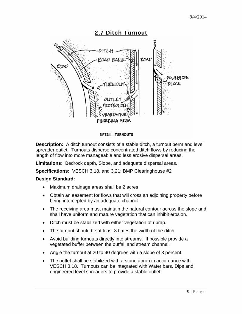
2.7 Ditch Turnout
Description: A ditch turnout consists of a stable ditch, a turnout berm and level spreader outlet. Turnouts disperse concentrated ditch flows by reducing the length of flow into more manageable and less erosive dispersal areas. Limitations: Bedrock depth, Slope, and adequate dispersal areas. Specifications: VESCH 3.18, and 3.21; BMP Clearinghouse #2 Design Standard:
• Maximum drainage areas shall be 2 acres
• Obtain an easement for flows that will cross an adjoining property before being intercepted by an adequate channel.
• The receiving area must maintain the natural contour across the slope and shall have uniform and mature vegetation that can inhibit erosion.
• Ditch must be stabilized with either vegetation of riprap.
• The turnout should be at least 3 times the width of the ditch.
• Avoid building turnouts directly into streams. If possible provide a vegetated buffer between the outfall and stream channel.
• Angle the turnout at 20 to 40 degrees with a slope of 3 percent.
• The outlet shall be stabilized with a stone apron in accordance with VESCH 3.18. Turnouts can be integrated with Water bars, Dips and engineered level spreaders to provide a stable outlet.
9 | P a g e
9/4/2014
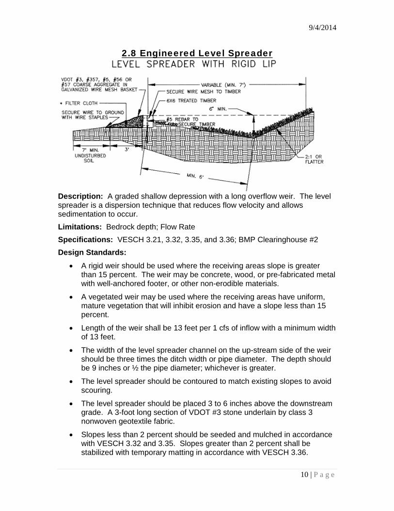
2.8 Engineered Level Spreader
Description: A graded shallow depression with a long overflow weir. The level spreader is a dispersion technique that reduces flow velocity and allows sedimentation to occur. Limitations: Bedrock depth; Flow Rate Specifications: VESCH 3.21, 3.32, 3.35, and 3.36; BMP Clearinghouse #2 Design Standards:
• A rigid weir should be used where the receiving areas slope is greater than 15 percent. The weir may be concrete, wood, or pre-fabricated metal with well-anchored footer, or other non-erodible materials.
• A vegetated weir may be used where the receiving areas have uniform, mature vegetation that will inhibit erosion and have a slope less than 15 percent.
• Length of the weir shall be 13 feet per 1 cfs of inflow with a minimum width of 13 feet.
• The width of the level spreader channel on the up-stream side of the weir should be three times the ditch width or pipe diameter. The depth should be 9 inches or ½ the pipe diameter; whichever is greater.
• The level spreader should be contoured to match existing slopes to avoid scouring.
• The level spreader should be placed 3 to 6 inches above the downstream grade. A 3-foot long section of VDOT #3 stone underlain by class 3 nonwoven geotextile fabric.
• Slopes less than 2 percent should be seeded and mulched in accordance with VESCH 3.32 and 3.35. Slopes greater than 2 percent shall be stabilized with temporary matting in accordance with VESCH 3.36.
10 | P a g e
9/4/2014
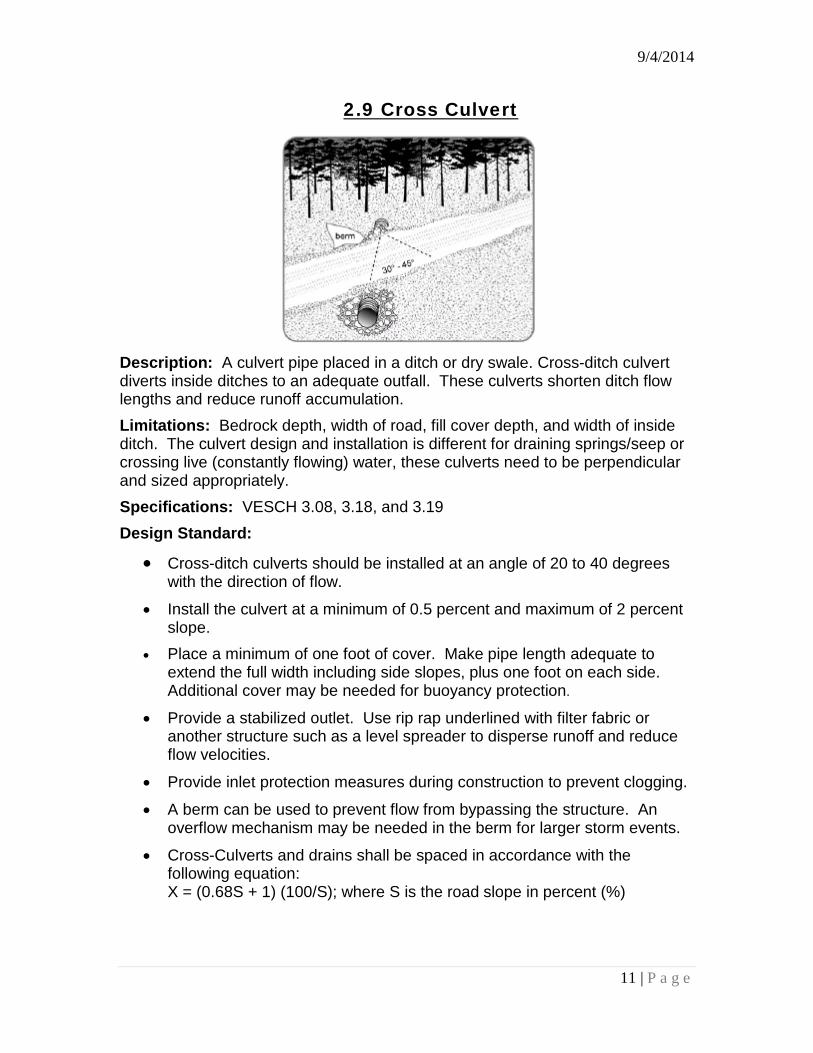
2.9 Cross Culvert
Description: A culvert pipe placed in a ditch or dry swale. Cross-ditch culvert diverts inside ditches to an adequate outfall. These culverts shorten ditch flow lengths and reduce runoff accumulation. Limitations: Bedrock depth, width of road, fill cover depth, and width of inside ditch. The culvert design and installation is different for draining springs/seep or crossing live (constantly flowing) water, these culverts need to be perpendicular and sized appropriately. Specifications: VESCH 3.08, 3.18, and 3.19 Design Standard:
• Cross-ditch culverts should be installed at an angle of 20 to 40 degrees with the direction of flow.
• Install the culvert at a minimum of 0.5 percent and maximum of 2 percent slope.
• Place a minimum of one foot of cover. Make pipe length adequate to extend the full width including side slopes, plus one foot on each side. Additional cover may be needed for buoyancy protection.
• Provide a stabilized outlet. Use rip rap underlined with filter fabric or another structure such as a level spreader to disperse runoff and reduce flow velocities.
• Provide inlet protection measures during construction to prevent clogging. • A berm can be used to prevent flow from bypassing the structure. An
overflow mechanism may be needed in the berm for larger storm events. • Cross-Culverts and drains shall be spaced in accordance with the
following equation: X = (0.68S + 1) (100/S); where S is the road slope in percent (%)
11 | P a g e
9/4/2014
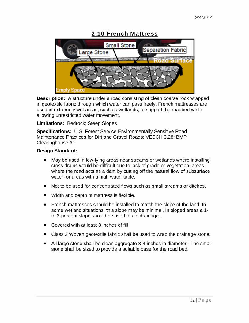
2.10 French Mattress
Description: A structure under a road consisting of clean coarse rock wrapped in geotextile fabric through which water can pass freely. French mattresses are used in extremely wet areas, such as wetlands, to support the roadbed while allowing unrestricted water movement. Limitations: Bedrock; Steep Slopes Specifications: U.S. Forest Service Environmentally Sensitive Road Maintenance Practices for Dirt and Gravel Roads; VESCH 3.28; BMP Clearinghouse #1 Design Standard:
• May be used in low-lying areas near streams or wetlands where installing cross drains would be difficult due to lack of grade or vegetation; areas where the road acts as a dam by cutting off the natural flow of subsurface water; or areas with a high water table.
• Not to be used for concentrated flows such as small streams or ditches. • Width and depth of mattress is flexible. • French mattresses should be installed to match the slope of the land. In
some wetland situations, this slope may be minimal. In sloped areas a 1- to 2-percent slope should be used to aid drainage.
• Covered with at least 8 inches of fill • Class 2 Woven geotextile fabric shall be used to wrap the drainage stone. • All large stone shall be clean aggregate 3-4 inches in diameter. The small
stone shall be sized to provide a suitable base for the road bed.
12 | P a g e

9/4/2014
2.11 Clearwater Crossing
Description: Clearwater crossings disconnect and disperse concentrated ditch runoff to reduce flow velocities prior to entering an undisturbed buffer or stream channel. Limitations: Available Floodplain Width; Slope Specifications: Chapter 4 U.S. Forest Service Environmentally Sensitive Road Maintenance Practices for Dirt and Gravel Roads; Design Standard:
• Provide a Grade Break on each side of the stream crossings.
• Contributing drainage area per ditch outfall shall be minimized with upslope diversion measures
• Area receiving dispersed flows shall have established vegetation that is uniform, mature enough to survive and will inhibit erosion.
• Eliminate ditches where possible through berm removal and raising the road profile approaching the stream.
• Locate drainage outlets away from streams and into vegetation when possible.
• Grade ditches in wide flood plains to drain away from stream crossings.
• Incorporates Dips, Grade Breaks, Turnouts, and Engineered Level Spreaders where needed.
• Disturbance of a stream buffer to achieve this design is not recommended.
13 | P a g e
9/4/2014
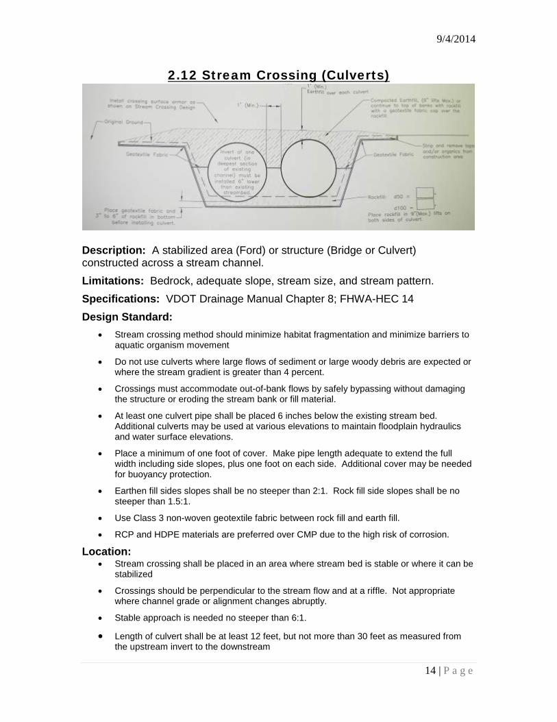
2.12 Stream Crossing (Culverts)
Description: A stabilized area (Ford) or structure (Bridge or Culvert) constructed across a stream channel. Limitations: Bedrock, adequate slope, stream size, and stream pattern. Specifications: VDOT Drainage Manual Chapter 8; FHWA-HEC 14 Design Standard:
• Stream crossing method should minimize habitat fragmentation and minimize barriers to aquatic organism movement
• Do not use culverts where large flows of sediment or large woody debris are expected or where the stream gradient is greater than 4 percent.
• Crossings must accommodate out-of-bank flows by safely bypassing without damaging the structure or eroding the stream bank or fill material.
• At least one culvert pipe shall be placed 6 inches below the existing stream bed. Additional culverts may be used at various elevations to maintain floodplain hydraulics and water surface elevations.
• Place a minimum of one foot of cover. Make pipe length adequate to extend the full width including side slopes, plus one foot on each side. Additional cover may be needed for buoyancy protection.
• Earthen fill sides slopes shall be no steeper than 2:1. Rock fill side slopes shall be no steeper than 1.5:1.
• Use Class 3 non-woven geotextile fabric between rock fill and earth fill.
• RCP and HDPE materials are preferred over CMP due to the high risk of corrosion.
Location: • Stream crossing shall be placed in an area where stream bed is stable or where it can be
stabilized
• Crossings should be perpendicular to the stream flow and at a riffle. Not appropriate where channel grade or alignment changes abruptly.
• Stable approach is needed no steeper than 6:1.
• Length of culvert shall be at least 12 feet, but not more than 30 feet as measured from the upstream invert to the downstream
14 | P a g e