Embed Size (px)
Citation preview
STORMWATER FACILITY MAINTENANCE MANUAL
Clark County Public Works Department Clean Water Program
January 2009

This page is purposely left blank for duplex printing.
i
Table of Contents TABLE OF CONTENTS........................................................................................................................................ I INTRODUCTION .................................................................................................................................................1 DETENTION POND.............................................................................................................................................5 INFILTRATION BASIN ........................................................................................................................................9 CATCH BASIN...................................................................................................................................................13 CLOSED DETENTION SYSTEM (TANKS/VAULT) ..........................................................................................17 CONTROL STRUCTURE/FLOW RESTRICTOR..............................................................................................19 DEBRIS BARRIER & ACCESS BARRIER (E.G. TRASH RACK).....................................................................21 ENERGY DISSIPATER .....................................................................................................................................23 TYPICAL BIOFILTRATION SWALE..................................................................................................................25 WET BIOFILTRATION SWALE.........................................................................................................................27 TREATMENT WETLAND ..................................................................................................................................29 FILTER STRIP...................................................................................................................................................31 WETPOND ........................................................................................................................................................33 WET VAULT ......................................................................................................................................................35 SAND FILTER (ABOVE GROUND/OPEN) .......................................................................................................37 SAND FILTER (BELOW GROUND/ENCLOSED).............................................................................................39 STORMWATER MANAGEMENT STORMFILTER ...........................................................................................41 OIL/WATER SEPARATOR (API TYPE) ............................................................................................................43 COALESCING PLATE OIL/WATER SEPARATOR ..........................................................................................45 CATCH BASIN INSERT ....................................................................................................................................47 MEDIA FILTER DRAIN (PREVIOUSLY REFERRED TO AS THE ECOLOGY EMBANKMENT).....................49 VORTECHS® STORMWATER TREATMENT SYSTEM...................................................................................51 SEDIMENT TRAP..............................................................................................................................................53 DRYWELL .........................................................................................................................................................55 INFILTRATION TRENCH ..................................................................................................................................57 FIELD INLET .....................................................................................................................................................59 ACCESS ROAD AND EASEMENT...................................................................................................................62 FENCE, GATE, AND/OR WATER QUALITY SIGN ..........................................................................................64 CONVEYANCE STORMWATER PIPE .............................................................................................................65 STORMWATER FACILITY DISCHARGE POINTS...........................................................................................66 VEGETATION MANAGEMENT.........................................................................................................................67

This page is purposely left blank for duplex printing.
Clark County Stormwater Facility Maintenance Manual – January 2009 1
Introduction Background
All businesses and government agencies have some form of stormwater drainage facilities. Stormwater facilities or storm sewers on private sites drain to roadside ditches, county storm sewer pipes, streams, or to groundwater from infiltration facilities. Storm sewers include pipes, catch basins, manholes, grassy treatment swales, ditches, drywells, ponds, oil/water separators, and any other structures that collect, convey, control, or treat stormwater. Requirements from the federal Clean Water Act and compliance with rules to protect threatened salmon under the federal Endangered Species Act also require that all storm drainage facilities be properly operated and maintained In November 1998, Clark County adopted the Water Quality Ordinance (as Chapter 13.26A CCC). The Water Quality Ordinance requires businesses and public agencies to use water quality protection practices, referred to as best management practices or BMPs, to eliminate or reduce pollution from their outdoor activities. The Water Quality Ordinance was amended in July 2000 to include minimum standards for maintaining drainage facilities. The water quality ordinance will be amended in 2008 to meet state standards for preventing pollutants from business and government operations from reaching the storm sewer. Development under Chapter 40.380 CCC is also required to maintain storm sewers. Chapter 40.380 CCC will be amended in 2008 to meet the 2007 NPDES Permit requirements to follow state guidelines for controlling stormwater and erosion on development and construction sites. New facilities are either transferred to county ownership and maintenance or maintained by the owner as private facilities. Purpose
This manual is intended to meet all storm sewer systems operation and maintenance requirements under Clark County Code Chapter 13.26A Water Quality, Chapter 40.380 Stormwater Controls, and the Stormwater Management Manual for Western Washington: Volume II (Washington Department of Ecology, April, 2005). It applies to county operations, as well as public or privately owned and operated systems in unincorporated areas of Clark County. Drainage systems are often in or near areas that are also fish and wildlife habitat. This manual helps make sure that storm sewer owners perform their maintenance in a way that conforms to regulations protecting fish and wildlife. Why Maintain Storm Sewer Facilities?
Along with keeping the site from flooding, properly maintained storm sewers can help reduce surface water and groundwater pollution. Many newer sites have stormwater control facilities designed to limit the environment damage and flooding damage by stormwater runoff. These systems cost many thousands of dollars to install and require more maintenance than a system of pipes and catch basins.
Clark County Stormwater Facility Maintenance Manual – January 2009 2
Storm sewer maintenance is necessary to protect streams, lakes, wetlands, and groundwater. Proper maintenance helps assure that: • Storm sewers operate as they were designed; • Storm sewers are cleaned of the pollutants that they trap, such as sediment and oils, so that
the site's storm sewers are not overwhelmed and become pollutant sources; • Sources of pollutants to storm sewers (such as leaky dumpsters) are removed.
What You Should Be Doing
This manual describes the steps you can take to assure that your storm sewers meet water quality requirements. If your site was approved for construction under county stormwater requirements adopted in 1994, the storm sewer system should have an approved plan for maintenance. This manual will help facility owners follow those requirements. Look for electronic copies of the manual on the Clark County web site: http://www.clark.wa.gov/water-resources/techassist/business.html
Method for Creating this Manual Stormwater Management Manual for Western Washington: Volume V This manual draws on other maintenance manuals to create an updated Stormwater Facility Maintenance Manual for Clark County. Along with documenting current county standards and practices, this manual includes maintenance practices from the Stormwater Management Manual for Western Washington: Volume IIV (Washington Department of Ecology, April, 2005), the Pierce County Stormwater Maintenance Manual for Private Facilities (2005), and the Clark County Stormwater Facility Maintenance Manual (July, 2000). The main sources are: • Washington Department of Ecology (April, 2005) Stormwater Management Manual for Western Washington: Volume V. • Pierce County (2005) Stormwater Maintenance Manual for Private Facilities.
Emergent Treatment Technologies Volume V, Chapter 12 of the SWMMWW addresses emerging treatment technologies. Since emerging technologies are rapidly evolving and it is not practical to update the SWMMWW every time a new device comes out, the Technology Assessment Protocol - Ecology (TAPE) was created as guidance for evaluating emerging stormwater treatment technologies. The TAPE can be found online at http://www.ecy.wa.gov/biblio/0210037.html.
Ecology assigns a General Use Level Designation (GULD) on emergent technologies that may be used Washington.

Clark County Stormwater Facility Maintenance Manual – January 2009 3
Maintenance standards in General Use Level Designation approvals for emergent technologies not found in the Clark County Stormwater Facility Maintenance Manual are adopted by reference and can be found at http://www.ecy.wa.gov/programs/wq/stormwater/newtech/technologies.html.
Mosquito Control Mosquitoes can be annoying and sometimes pose a serious risk to public health. In certain areas of the United States, mosquitoes can transmit diseases such as West Nile Virus and equine encephalitis. To combat mosquitoes and the public health hazards they present, Clark County has established mosquito control program. Information on the the Clark County Mosquito Control District can be accessed on line at http://www.clark.wa.gov/mosquito/. Mosquito control programs place a high priority on trying to prevent a large population of adult mosquitoes from developing so that additional controls may not be necessary. Since mosquitoes must have water to breed, methods of prevention may include identifying stormwater infrastructure such as catch basins, retention/detention systems, and other water holding areas that may harbor mosquitoes. If mosquitoes are identified during stormwater facility maintenance or inspection activities and are a concern, a request to the Clark County Mosquito Control District for service or information regarding mosquito control can be made through either the 24-hour service request line, (360) 397-8430.

Clark County Stormwater Facility Maintenance Manual – January 2009 4
Clark County Stormwater Facility Maintenance Manual – January 2009 5
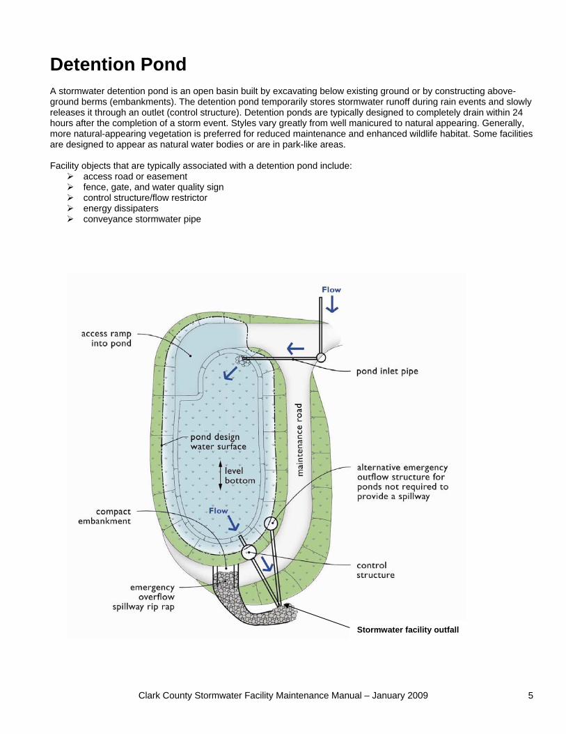
Detention Pond A stormwater detention pond is an open basin built by excavating below existing ground or by constructing above-ground berms (embankments). The detention pond temporarily stores stormwater runoff during rain events and slowly releases it through an outlet (control structure). Detention ponds are typically designed to completely drain within 24 hours after the completion of a storm event. Styles vary greatly from well manicured to natural appearing. Generally, more natural-appearing vegetation is preferred for reduced maintenance and enhanced wildlife habitat. Some facilities are designed to appear as natural water bodies or are in park-like areas. Facility objects that are typically associated with a detention pond include:
access road or easement fence, gate, and water quality sign control structure/flow restrictor energy dissipaters conveyance stormwater pipe
Stormwater facility outfall
Clark County Stormwater Facility Maintenance Manual – January 2009 6
Detention Pond Drainage System Feature
Potential Defect
Conditions When Maintenance Is Needed Results Expected When Maintenance Is Performed Or Not Needed
Any trash and debris which exceed 5 cubic feet per 1,000 square feet (this is about equal to the amount of trash it would take to fill up one standard size garbage can). In general, there should be no visual evidence of dumping.
Trash and Debris
If less than threshold all trash and debris will be removed as part of next scheduled maintenance.
Trash and debris cleared from site.
Any poisonous or nuisance vegetation which may constitute a hazard to maintenance personnel or the public.
No danger of poisonous vegetation where maintenance personnel or the public might normally be. (Coordinate with Clark County Weed Management department)
Any evidence of noxious weeds as defined by State or local regulations.
Complete eradication of noxious weeds may not be possible. Compliance with State or local eradication policies required
Poisonous Vegetation and noxious weeds
(Apply requirements of adopted IPM policies for the use of herbicides).
Any evidence of oil, gasoline, contaminants or other pollutants
Contaminants and Pollution
(Coordinate removal/cleanup with local water quality response agency).
No contaminants or pollutants present.
Rodent Holes Any evidence of rodent holes if facility is acting as a dam or berm, or any evidence of water piping through dam or berm via rodent holes.
Rodents destroyed and dam or berm repaired. (Coordinate with Clark County Maintenance and Operations department; coordinate with Ecology Dam Safety Office if pond exceeds 10 acre-feet.) Facility is returned to design function. Beaver Dams Dam results in change or function of the facility. (Coordinate trapping of beavers and removal of dams with appropriate permitting agencies)
Insects destroyed or removed from site. Insects When insects such as wasps and hornets interfere with maintenance activities. Apply insecticides in compliance with adopted
Clark County Maintenance and Operations policies.
Tree growth does not allow maintenance access or interferes with maintenance activity (i.e., slope mowing, silt removal, vactoring, or equipment movements). If trees are not interfering with access or maintenance, do not remove.
Trees do not hinder maintenance activities. Harvested trees should be recycled into mulch or other beneficial uses (e.g., alders for firewood).
If dead, diseased, or dying trees are identified Remove hazard Trees
General
Tree Growth and Hazard Trees
(Use a certified Arborist to determine health of tree or removal requirements)
Eroded damage over 2 inches deep where cause of damage is still present or where there is potential for continued erosion.
Slopes should be stabilized using appropriate erosion control measure(s); e.g., rock reinforcement, planting of grass, compaction.
Side Slopes of Pond
Erosion
Any erosion observed on a compacted berm embankment.
If erosion is occurring on compacted berms a licensed civil engineer should be consulted to resolve source of erosion.
Clark County Stormwater Facility Maintenance Manual – January 2009 7
Detention Pond (Continued) Drainage System Feature
Potential Defect
Conditions When Maintenance Is Needed Results Expected When Maintenance Is Performed Or Not Needed
Sediment Accumulated sediment that exceeds 10% of the designed pond depth unless otherwise specified or affects inletting or outletting condition of the facility.
Sediment cleaned out to designed pond shape and depth; pond reseeded if necessary to control erosion.
Storage Area
Liner (If Applicable)
Liner is visible and has more than three 1/4-inch holes in it.
Liner repaired or replaced. Liner is fully covered.
Any part of berm which has settled 4 inches lower than the design elevation. If settlement is apparent, measure berm to determine amount of settlement.
Settlements
Settling can be an indication of more severe problems with the berm or outlet works. A licensed civil engineer should be consulted to determine the source of the settlement.
Dike is built back to the design elevation.
Discernable water flow through pond berm. Ongoing erosion with potential for erosion to continue.
Pond Berms (Dikes)
Piping
(Recommend a Geotechnical engineer be called in to inspect and evaluate condition and recommend repair of condition.
Piping eliminated. Erosion potential resolved.
Tree growth on emergency spillways creates blockage problems and may cause failure of the berm due to uncontrolled overtopping.
Tree Growth
Tree growth on berms over 4 feet in height may lead to piping through the berm which could lead to failure of the berm.
Trees should be removed. If root system is small (base less than 4 inches) the root system may be left in place. Otherwise the roots should be removed and the berm restored. A licensed civil engineer should be consulted for proper berm/spillway restoration.
Discernable water flow through pond berm. Ongoing erosion with potential for erosion to continue.
Emergency Overflow/ Spillway and Berms Over 4 Feet in Height.
Piping
(Recommend a Geotechnical engineer be called in to inspect and evaluate condition and recommend repair of condition.
Piping eliminated. Erosion potential resolved.
Only one layer of rock exists above native soil in area five square feet or larger, or any exposure of native soil at the top of out flow path of spillway.
Rocks and pad depth are restored to design standards.
Rock Missing
(Rip-rap on inside slopes need not be replaced.)
Eroded damage over 2 inches deep where cause of damage is still present or where there is potential for continued erosion.
Slopes should be stabilized using appropriate erosion control measure(s); e.g., rock reinforcement, planting of grass, compaction.
Emergency Overflow/ Spillway
Erosion
Any erosion observed on a compacted berm embankment.
If erosion is occurring on compacted berms a licensed civil engineer should be consulted to resolve source of erosion.

Clark County Stormwater Facility Maintenance Manual – January 2009 8
Clark County Stormwater Facility Maintenance Manual – January 2009 9
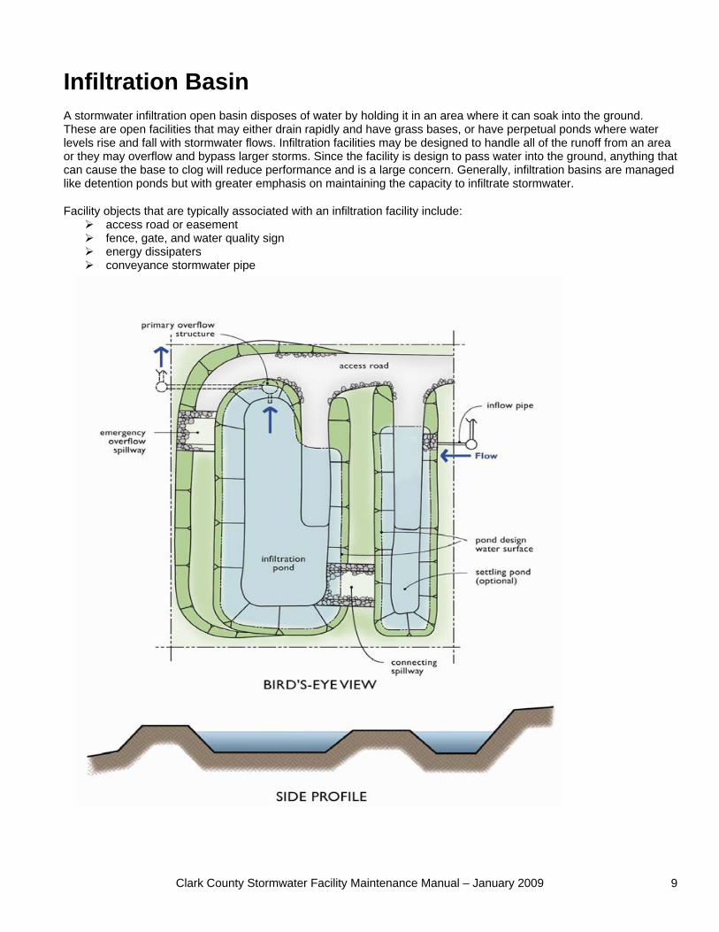
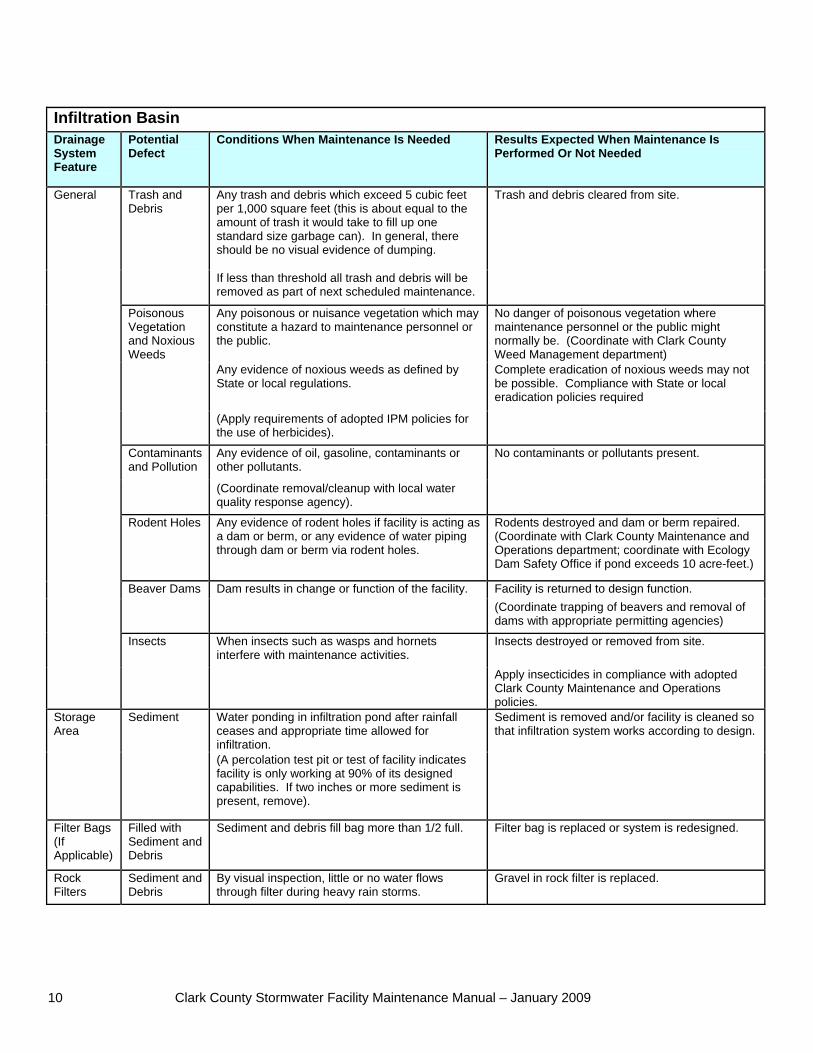
Infiltration Basin A stormwater infiltration open basin disposes of water by holding it in an area where it can soak into the ground. These are open facilities that may either drain rapidly and have grass bases, or have perpetual ponds where water levels rise and fall with stormwater flows. Infiltration facilities may be designed to handle all of the runoff from an area or they may overflow and bypass larger storms. Since the facility is design to pass water into the ground, anything that can cause the base to clog will reduce performance and is a large concern. Generally, infiltration basins are managed like detention ponds but with greater emphasis on maintaining the capacity to infiltrate stormwater.
Facility objects that are typically associated with an infiltration facility include: access road or easement fence, gate, and water quality sign energy dissipaters conveyance stormwater pipe
Clark County Stormwater Facility Maintenance Manual – January 2009 10
Infiltration Basin Drainage System Feature
Potential Defect
Conditions When Maintenance Is Needed Results Expected When Maintenance Is Performed Or Not Needed
Any trash and debris which exceed 5 cubic feet per 1,000 square feet (this is about equal to the amount of trash it would take to fill up one standard size garbage can). In general, there should be no visual evidence of dumping.
Trash and Debris
If less than threshold all trash and debris will be removed as part of next scheduled maintenance.
Trash and debris cleared from site.
Any poisonous or nuisance vegetation which may constitute a hazard to maintenance personnel or the public.
No danger of poisonous vegetation where maintenance personnel or the public might normally be. (Coordinate with Clark County Weed Management department)
Any evidence of noxious weeds as defined by State or local regulations.
Poisonous Vegetation and Noxious Weeds
(Apply requirements of adopted IPM policies for the use of herbicides).
Complete eradication of noxious weeds may not be possible. Compliance with State or local eradication policies required
Any evidence of oil, gasoline, contaminants or other pollutants.
Contaminants and Pollution
(Coordinate removal/cleanup with local water quality response agency).
No contaminants or pollutants present.
Rodent Holes Any evidence of rodent holes if facility is acting as a dam or berm, or any evidence of water piping through dam or berm via rodent holes.
Rodents destroyed and dam or berm repaired. (Coordinate with Clark County Maintenance and Operations department; coordinate with Ecology Dam Safety Office if pond exceeds 10 acre-feet.)
Dam results in change or function of the facility. Facility is returned to design function. Beaver Dams (Coordinate trapping of beavers and removal of
dams with appropriate permitting agencies)
When insects such as wasps and hornets interfere with maintenance activities.
Insects destroyed or removed from site.
General
Insects
Apply insecticides in compliance with adopted Clark County Maintenance and Operations policies.
Water ponding in infiltration pond after rainfall ceases and appropriate time allowed for infiltration.
Storage Area
Sediment
(A percolation test pit or test of facility indicates facility is only working at 90% of its designed capabilities. If two inches or more sediment is present, remove).
Sediment is removed and/or facility is cleaned so that infiltration system works according to design.
Filter Bags (If Applicable)
Filled with Sediment and Debris
Sediment and debris fill bag more than 1/2 full. Filter bag is replaced or system is redesigned.
Rock Filters
Sediment and Debris
By visual inspection, little or no water flows through filter during heavy rain storms.
Gravel in rock filter is replaced.
Clark County Stormwater Facility Maintenance Manual – January 2009 11
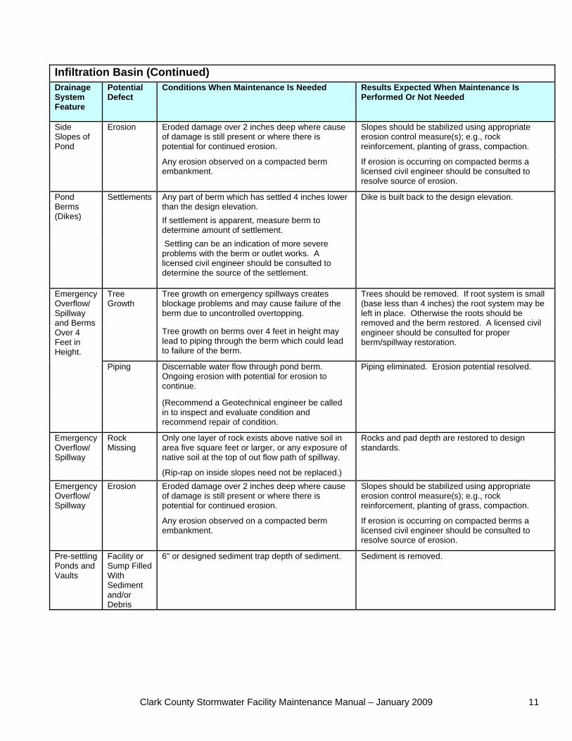
Infiltration Basin (Continued) Drainage System Feature
Potential Defect
Conditions When Maintenance Is Needed Results Expected When Maintenance Is Performed Or Not Needed
Eroded damage over 2 inches deep where cause of damage is still present or where there is potential for continued erosion.
Slopes should be stabilized using appropriate erosion control measure(s); e.g., rock reinforcement, planting of grass, compaction.
Side Slopes of Pond
Erosion
Any erosion observed on a compacted berm embankment.
If erosion is occurring on compacted berms a licensed civil engineer should be consulted to resolve source of erosion.
Any part of berm which has settled 4 inches lower than the design elevation. If settlement is apparent, measure berm to determine amount of settlement.
Pond Berms (Dikes)
Settlements
Settling can be an indication of more severe problems with the berm or outlet works. A licensed civil engineer should be consulted to determine the source of the settlement.
Dike is built back to the design elevation.
Tree growth on emergency spillways creates blockage problems and may cause failure of the berm due to uncontrolled overtopping.
Tree Growth
Tree growth on berms over 4 feet in height may lead to piping through the berm which could lead to failure of the berm.
Trees should be removed. If root system is small (base less than 4 inches) the root system may be left in place. Otherwise the roots should be removed and the berm restored. A licensed civil engineer should be consulted for proper berm/spillway restoration.
Discernable water flow through pond berm. Ongoing erosion with potential for erosion to continue.
Piping eliminated. Erosion potential resolved.
Emergency Overflow/ Spillway and Berms Over 4 Feet in Height.
Piping
(Recommend a Geotechnical engineer be called in to inspect and evaluate condition and recommend repair of condition.
Only one layer of rock exists above native soil in area five square feet or larger, or any exposure of native soil at the top of out flow path of spillway.
Rocks and pad depth are restored to design standards.
Emergency Overflow/ Spillway
Rock Missing
(Rip-rap on inside slopes need not be replaced.) Eroded damage over 2 inches deep where cause of damage is still present or where there is potential for continued erosion.
Slopes should be stabilized using appropriate erosion control measure(s); e.g., rock reinforcement, planting of grass, compaction.
Emergency Overflow/ Spillway
Erosion
Any erosion observed on a compacted berm embankment.
If erosion is occurring on compacted berms a licensed civil engineer should be consulted to resolve source of erosion.
Pre-settling Ponds and Vaults
Facility or Sump Filled With Sediment and/or Debris
6" or designed sediment trap depth of sediment. Sediment is removed.

Clark County Stormwater Facility Maintenance Manual – January 2009 12
Clark County Stormwater Facility Maintenance Manual – January 2009 13
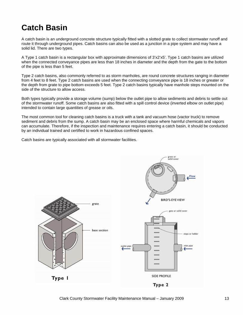
Catch Basin A catch basin is an underground concrete structure typically fitted with a slotted grate to collect stormwater runoff and route it through underground pipes. Catch basins can also be used as a junction in a pipe system and may have a solid lid. There are two types. A Type 1 catch basin is a rectangular box with approximate dimensions of 3’x2’x5’. Type 1 catch basins are utilized when the connected conveyance pipes are less than 18 inches in diameter and the depth from the gate to the bottom of the pipe is less than 5 feet. Type 2 catch basins, also commonly referred to as storm manholes, are round concrete structures ranging in diameter from 4 feet to 8 feet. Type 2 catch basins are used when the connecting conveyance pipe is 18 inches or greater or the depth from grate to pipe bottom exceeds 5 feet. Type 2 catch basins typically have manhole steps mounted on the side of the structure to allow access. Both types typically provide a storage volume (sump) below the outlet pipe to allow sediments and debris to settle out of the stormwater runoff. Some catch basins are also fitted with a spill control device (inverted elbow on outlet pipe) intended to contain large quantities of grease or oils. The most common tool for cleaning catch basins is a truck with a tank and vacuum hose (vactor truck) to remove sediment and debris from the sump. A catch basin may be an enclosed space where harmful chemicals and vapors can accumulate. Therefore, if the inspection and maintenance requires entering a catch basin, it should be conducted by an individual trained and certified to work in hazardous confined spaces. Catch basins are typically associated with all stormwater facilities.
Clark County Stormwater Facility Maintenance Manual – January 2009 14
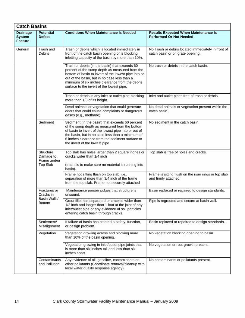
Catch Basins Drainage System Feature
Potential Defect
Conditions When Maintenance Is Needed Results Expected When Maintenance Is Performed Or Not Needed
Trash or debris which is located immediately in front of the catch basin opening or is blocking inletting capacity of the basin by more than 10%.
No Trash or debris located immediately in front of catch basin or on grate opening.
Trash or debris (in the basin) that exceeds 60 percent of the sump depth as measured from the bottom of basin to invert of the lowest pipe into or out of the basin, but in no case less than a minimum of six inches clearance from the debris surface to the invert of the lowest pipe.
No trash or debris in the catch basin.
Trash or debris in any inlet or outlet pipe blocking more than 1/3 of its height.
Inlet and outlet pipes free of trash or debris.
Trash and Debris
Dead animals or vegetation that could generate odors that could cause complaints or dangerous gases (e.g., methane).
No dead animals or vegetation present within the catch basin.
Sediment Sediment (in the basin) that exceeds 60 percent of the sump depth as measured from the bottom of basin to invert of the lowest pipe into or out of the basin, but in no case less than a minimum of 6 inches clearance from the sediment surface to the invert of the lowest pipe.
No sediment in the catch basin
Top slab has holes larger than 2 square inches or cracks wider than 1/4 inch (Intent is to make sure no material is running into basin).
Top slab is free of holes and cracks. Structure Damage to Frame and/or Top Slab
Frame not sitting flush on top slab, i.e., separation of more than 3/4 inch of the frame from the top slab. Frame not securely attached
Frame is sitting flush on the riser rings or top slab and firmly attached.
Maintenance person judges that structure is unsound.
Basin replaced or repaired to design standards. Fractures or Cracks in Basin Walls/ Bottom Grout fillet has separated or cracked wider than
1/2 inch and longer than 1 foot at the joint of any inlet/outlet pipe or any evidence of soil particles entering catch basin through cracks.
Pipe is regrouted and secure at basin wall.
Settlement/ Misalignment
If failure of basin has created a safety, function, or design problem.
Basin replaced or repaired to design standards.
Vegetation growing across and blocking more than 10% of the basin opening.
No vegetation blocking opening to basin. Vegetation
Vegetation growing in inlet/outlet pipe joints that is more than six inches tall and less than six inches apart.
No vegetation or root growth present.
General
Contaminants and Pollution
Any evidence of oil, gasoline, contaminants or other pollutants (Coordinate removal/cleanup with local water quality response agency).
No contaminants or pollutants present.
Clark County Stormwater Facility Maintenance Manual – January 2009 15
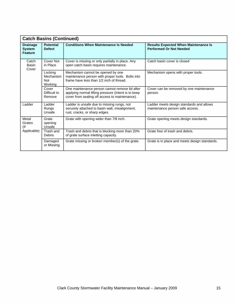
Catch Basins (Continued) Drainage System Feature
Potential Defect
Conditions When Maintenance Is Needed Results Expected When Maintenance Is Performed Or Not Needed
Cover Not in Place
Cover is missing or only partially in place. Any open catch basin requires maintenance.
Catch basin cover is closed
Locking Mechanism Not Working
Mechanism cannot be opened by one maintenance person with proper tools. Bolts into frame have less than 1/2 inch of thread.
Mechanism opens with proper tools.
Catch Basin Cover
Cover Difficult to Remove
One maintenance person cannot remove lid after applying normal lifting pressure (Intent is to keep cover from sealing off access to maintenance).
Cover can be removed by one maintenance person.
Ladder Ladder Rungs Unsafe
Ladder is unsafe due to missing rungs, not securely attached to basin wall, misalignment, rust, cracks, or sharp edges.
Ladder meets design standards and allows maintenance person safe access.
Grate opening Unsafe
Grate with opening wider than 7/8 inch. Grate opening meets design standards.
Trash and Debris
Trash and debris that is blocking more than 20% of grate surface inletting capacity.
Grate free of trash and debris.
Metal Grates (If Applicable)
Damaged or Missing.
Grate missing or broken member(s) of the grate. Grate is in place and meets design standards.

Clark County Stormwater Facility Maintenance Manual – January 2009 16
Clark County Stormwater Facility Maintenance Manual – January 2009 17
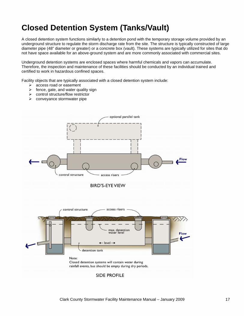
Closed Detention System (Tanks/Vault) A closed detention system functions similarly to a detention pond with the temporary storage volume provided by an underground structure to regulate the storm discharge rate from the site. The structure is typically constructed of large diameter pipe (48” diameter or greater) or a concrete box (vault). These systems are typically utilized for sites that do not have space available for an above-ground system and are more commonly associated with commercial sites. Underground detention systems are enclosed spaces where harmful chemicals and vapors can accumulate. Therefore, the inspection and maintenance of these facilities should be conducted by an individual trained and certified to work in hazardous confined spaces. Facility objects that are typically associated with a closed detention system include:
access road or easement fence, gate, and water quality sign control structure/flow restrictor conveyance stormwater pipe
Clark County Stormwater Facility Maintenance Manual – January 2009 18
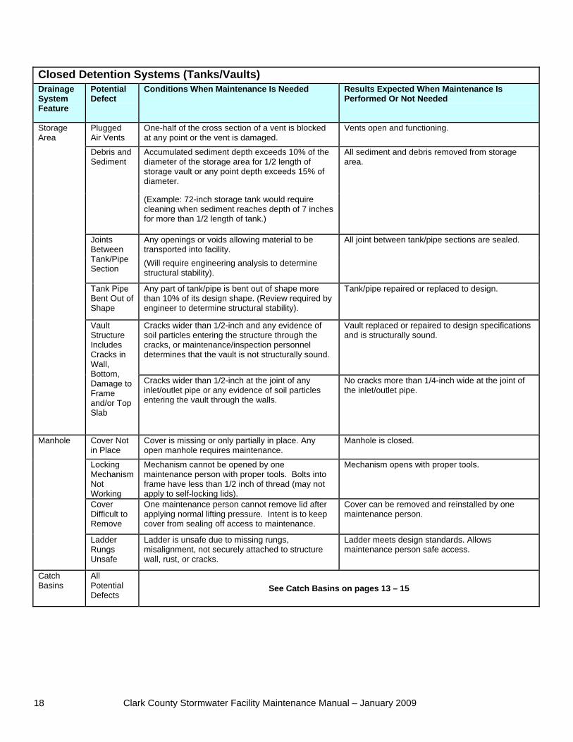
Closed Detention Systems (Tanks/Vaults) Drainage System Feature
Potential Defect
Conditions When Maintenance Is Needed Results Expected When Maintenance Is Performed Or Not Needed
Plugged Air Vents
One-half of the cross section of a vent is blocked at any point or the vent is damaged.
Vents open and functioning.
Accumulated sediment depth exceeds 10% of the diameter of the storage area for 1/2 length of storage vault or any point depth exceeds 15% of diameter.
Debris and Sediment
(Example: 72-inch storage tank would require cleaning when sediment reaches depth of 7 inches for more than 1/2 length of tank.)
All sediment and debris removed from storage area.
Any openings or voids allowing material to be transported into facility.
Joints Between Tank/Pipe Section
(Will require engineering analysis to determine structural stability).
All joint between tank/pipe sections are sealed.
Tank Pipe Bent Out of Shape
Any part of tank/pipe is bent out of shape more than 10% of its design shape. (Review required by engineer to determine structural stability).
Tank/pipe repaired or replaced to design.
Cracks wider than 1/2-inch and any evidence of soil particles entering the structure through the cracks, or maintenance/inspection personnel determines that the vault is not structurally sound.
Vault replaced or repaired to design specifications and is structurally sound.
Storage Area
Vault Structure Includes Cracks in Wall, Bottom, Damage to Frame and/or Top Slab
Cracks wider than 1/2-inch at the joint of any inlet/outlet pipe or any evidence of soil particles entering the vault through the walls.
No cracks more than 1/4-inch wide at the joint of the inlet/outlet pipe.
Cover Not in Place
Cover is missing or only partially in place. Any open manhole requires maintenance.
Manhole is closed.
Locking Mechanism Not Working
Mechanism cannot be opened by one maintenance person with proper tools. Bolts into frame have less than 1/2 inch of thread (may not apply to self-locking lids).
Mechanism opens with proper tools.
Cover Difficult to Remove
One maintenance person cannot remove lid after applying normal lifting pressure. Intent is to keep cover from sealing off access to maintenance.
Cover can be removed and reinstalled by one maintenance person.
Manhole
Ladder Rungs Unsafe
Ladder is unsafe due to missing rungs, misalignment, not securely attached to structure wall, rust, or cracks.
Ladder meets design standards. Allows maintenance person safe access.
Catch Basins
All Potential Defects
See Catch Basins on pages 13 – 15
Clark County Stormwater Facility Maintenance Manual – January 2009 19
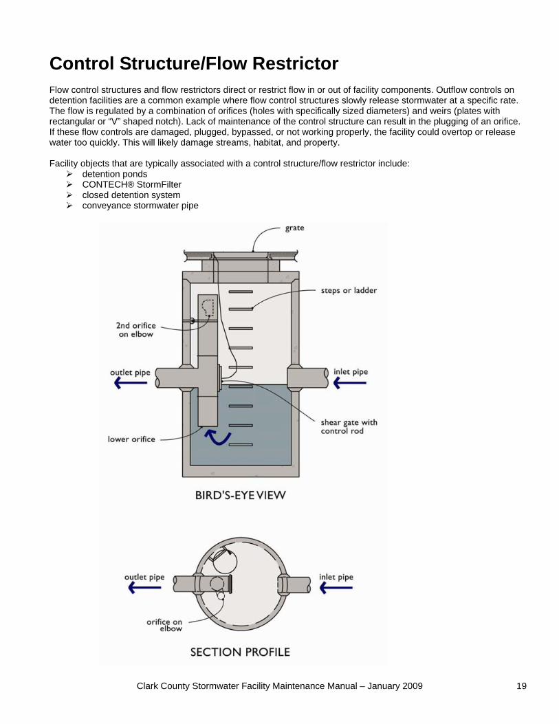
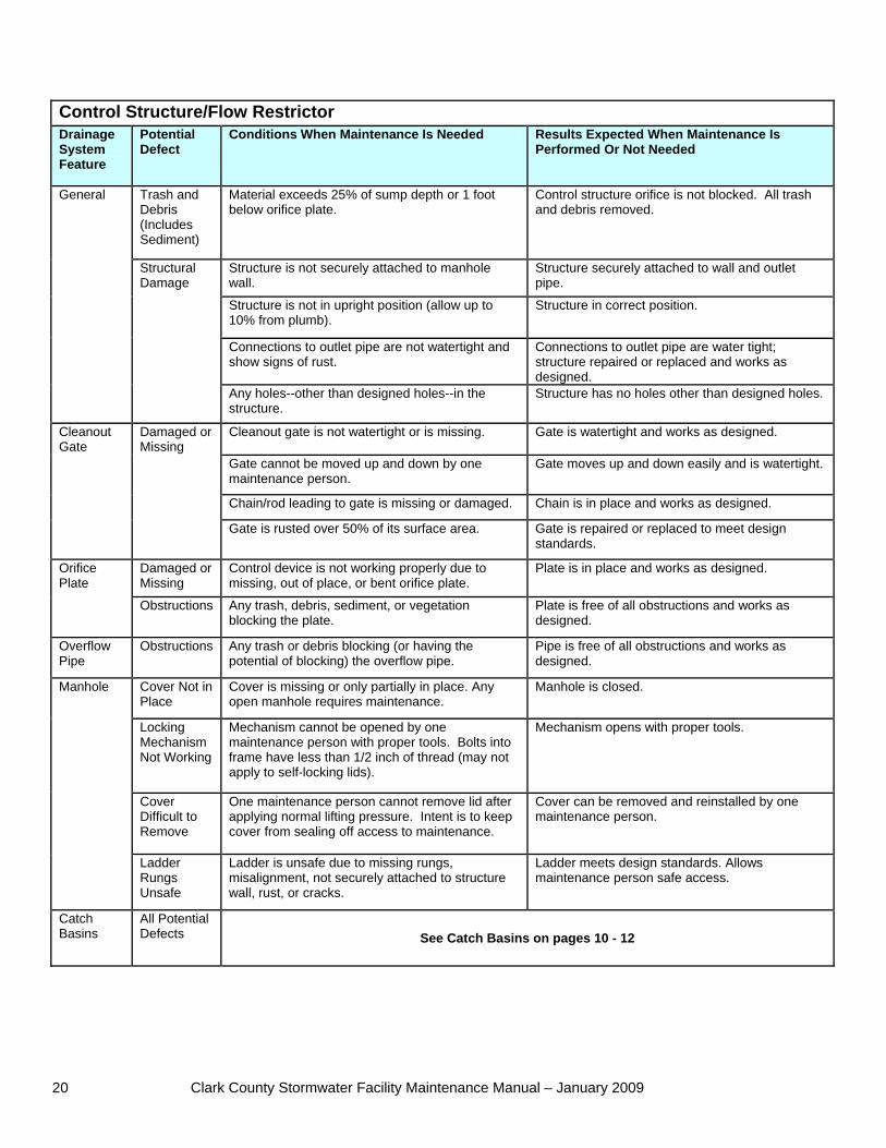
Control Structure/Flow Restrictor Flow control structures and flow restrictors direct or restrict flow in or out of facility components. Outflow controls on detention facilities are a common example where flow control structures slowly release stormwater at a specific rate. The flow is regulated by a combination of orifices (holes with specifically sized diameters) and weirs (plates with rectangular or “V” shaped notch). Lack of maintenance of the control structure can result in the plugging of an orifice. If these flow controls are damaged, plugged, bypassed, or not working properly, the facility could overtop or release water too quickly. This will likely damage streams, habitat, and property. Facility objects that are typically associated with a control structure/flow restrictor include:
detention ponds CONTECH® StormFilter closed detention system conveyance stormwater pipe
Clark County Stormwater Facility Maintenance Manual – January 2009 20
Control Structure/Flow Restrictor Drainage System Feature
Potential Defect
Conditions When Maintenance Is Needed Results Expected When Maintenance Is Performed Or Not Needed
Trash and Debris (Includes Sediment)
Material exceeds 25% of sump depth or 1 foot below orifice plate.
Control structure orifice is not blocked. All trash and debris removed.
Structure is not securely attached to manhole wall.
Structure securely attached to wall and outlet pipe.
Structure is not in upright position (allow up to 10% from plumb).
Structure in correct position.
Connections to outlet pipe are not watertight and show signs of rust.
Connections to outlet pipe are water tight; structure repaired or replaced and works as designed.
General
Structural Damage
Any holes--other than designed holes--in the structure.
Structure has no holes other than designed holes.
Cleanout gate is not watertight or is missing. Gate is watertight and works as designed.
Gate cannot be moved up and down by one maintenance person.
Gate moves up and down easily and is watertight.
Chain/rod leading to gate is missing or damaged. Chain is in place and works as designed.
Cleanout Gate
Damaged or Missing
Gate is rusted over 50% of its surface area. Gate is repaired or replaced to meet design standards.
Damaged or Missing
Control device is not working properly due to missing, out of place, or bent orifice plate.
Plate is in place and works as designed. Orifice Plate
Obstructions Any trash, debris, sediment, or vegetation blocking the plate.
Plate is free of all obstructions and works as designed.
Overflow Pipe
Obstructions Any trash or debris blocking (or having the potential of blocking) the overflow pipe.
Pipe is free of all obstructions and works as designed.
Cover Not in Place
Cover is missing or only partially in place. Any open manhole requires maintenance.
Manhole is closed.
Locking Mechanism Not Working
Mechanism cannot be opened by one maintenance person with proper tools. Bolts into frame have less than 1/2 inch of thread (may not apply to self-locking lids).
Mechanism opens with proper tools.
Cover Difficult to Remove
One maintenance person cannot remove lid after applying normal lifting pressure. Intent is to keep cover from sealing off access to maintenance.
Cover can be removed and reinstalled by one maintenance person.
Manhole
Ladder Rungs Unsafe
Ladder is unsafe due to missing rungs, misalignment, not securely attached to structure wall, rust, or cracks.
Ladder meets design standards. Allows maintenance person safe access.
Catch Basins
All Potential Defects See Catch Basins on pages 10 - 12
Clark County Stormwater Facility Maintenance Manual – January 2009 21
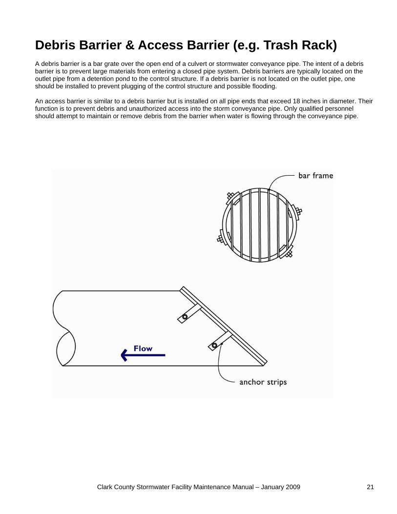
Debris Barrier & Access Barrier (e.g. Trash Rack) A debris barrier is a bar grate over the open end of a culvert or stormwater conveyance pipe. The intent of a debris barrier is to prevent large materials from entering a closed pipe system. Debris barriers are typically located on the outlet pipe from a detention pond to the control structure. If a debris barrier is not located on the outlet pipe, one should be installed to prevent plugging of the control structure and possible flooding. An access barrier is similar to a debris barrier but is installed on all pipe ends that exceed 18 inches in diameter. Their function is to prevent debris and unauthorized access into the storm conveyance pipe. Only qualified personnel should attempt to maintain or remove debris from the barrier when water is flowing through the conveyance pipe.
Clark County Stormwater Facility Maintenance Manual – January 2009 22
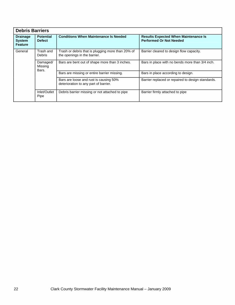
Debris Barriers Drainage System Feature
Potential Defect
Conditions When Maintenance Is Needed Results Expected When Maintenance Is Performed Or Not Needed
Trash and Debris
Trash or debris that is plugging more than 20% of the openings in the barrier.
Barrier cleared to design flow capacity.
Bars are bent out of shape more than 3 inches. Bars in place with no bends more than 3/4 inch.
Bars are missing or entire barrier missing. Bars in place according to design.
Damaged/ Missing Bars.
Bars are loose and rust is causing 50% deterioration to any part of barrier.
Barrier replaced or repaired to design standards.
General
Inlet/Outlet Pipe
Debris barrier missing or not attached to pipe Barrier firmly attached to pipe
Clark County Stormwater Facility Maintenance Manual – January 2009 23
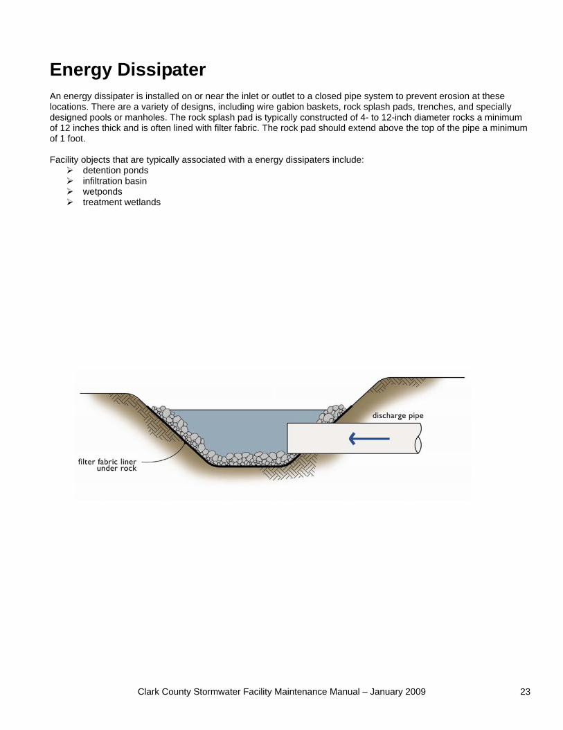
Energy Dissipater An energy dissipater is installed on or near the inlet or outlet to a closed pipe system to prevent erosion at these locations. There are a variety of designs, including wire gabion baskets, rock splash pads, trenches, and specially designed pools or manholes. The rock splash pad is typically constructed of 4- to 12-inch diameter rocks a minimum of 12 inches thick and is often lined with filter fabric. The rock pad should extend above the top of the pipe a minimum of 1 foot. Facility objects that are typically associated with a energy dissipaters include:
detention ponds infiltration basin wetponds treatment wetlands
Clark County Stormwater Facility Maintenance Manual – January 2009 24
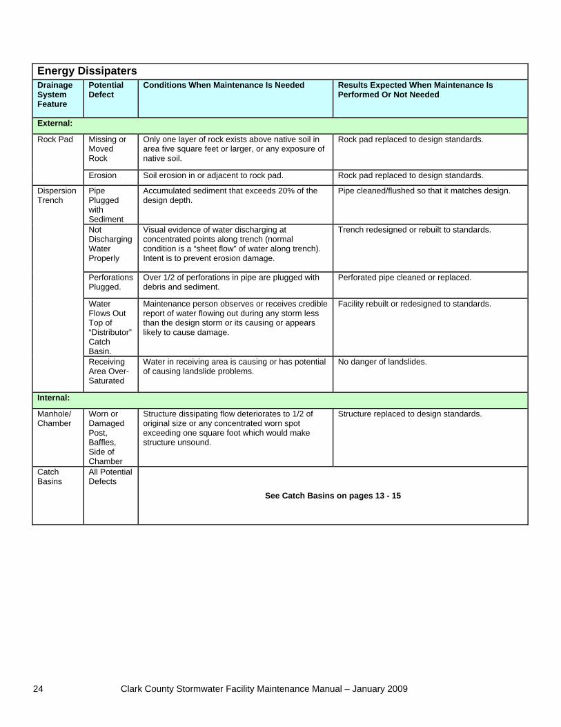
Energy Dissipaters Drainage System Feature
Potential Defect
Conditions When Maintenance Is Needed Results Expected When Maintenance Is Performed Or Not Needed
External:
Missing or Moved Rock
Only one layer of rock exists above native soil in area five square feet or larger, or any exposure of native soil.
Rock pad replaced to design standards. Rock Pad
Erosion Soil erosion in or adjacent to rock pad. Rock pad replaced to design standards.
Pipe Plugged with Sediment
Accumulated sediment that exceeds 20% of the design depth.
Pipe cleaned/flushed so that it matches design.
Not Discharging Water Properly
Visual evidence of water discharging at concentrated points along trench (normal condition is a “sheet flow” of water along trench). Intent is to prevent erosion damage.
Trench redesigned or rebuilt to standards.
Perforations Plugged.
Over 1/2 of perforations in pipe are plugged with debris and sediment.
Perforated pipe cleaned or replaced.
Water Flows Out Top of “Distributor” Catch Basin.
Maintenance person observes or receives credible report of water flowing out during any storm less than the design storm or its causing or appears likely to cause damage.
Facility rebuilt or redesigned to standards.
Dispersion Trench
Receiving Area Over-Saturated
Water in receiving area is causing or has potential of causing landslide problems.
No danger of landslides.
Internal:
Manhole/ Chamber
Worn or Damaged Post, Baffles, Side of Chamber
Structure dissipating flow deteriorates to 1/2 of original size or any concentrated worn spot exceeding one square foot which would make structure unsound.
Structure replaced to design standards.
Catch Basins
All Potential Defects
See Catch Basins on pages 13 - 15
Clark County Stormwater Facility Maintenance Manual – January 2009 25
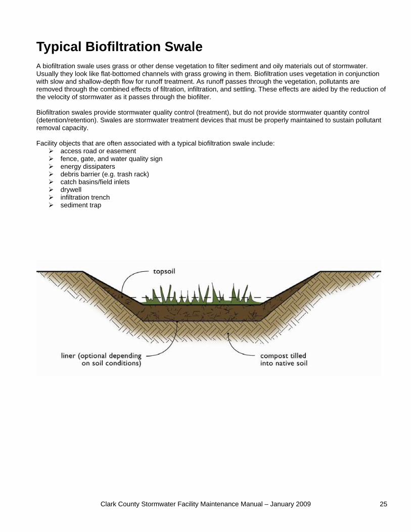
Typical Biofiltration Swale A biofiltration swale uses grass or other dense vegetation to filter sediment and oily materials out of stormwater. Usually they look like flat-bottomed channels with grass growing in them. Biofiltration uses vegetation in conjunction with slow and shallow-depth flow for runoff treatment. As runoff passes through the vegetation, pollutants are removed through the combined effects of filtration, infiltration, and settling. These effects are aided by the reduction of the velocity of stormwater as it passes through the biofilter. Biofiltration swales provide stormwater quality control (treatment), but do not provide stormwater quantity control (detention/retention). Swales are stormwater treatment devices that must be properly maintained to sustain pollutant removal capacity. Facility objects that are often associated with a typical biofiltration swale include:
access road or easement fence, gate, and water quality sign energy dissipaters debris barrier (e.g. trash rack) catch basins/field inlets drywell infiltration trench sediment trap
Clark County Stormwater Facility Maintenance Manual – January 2009 26
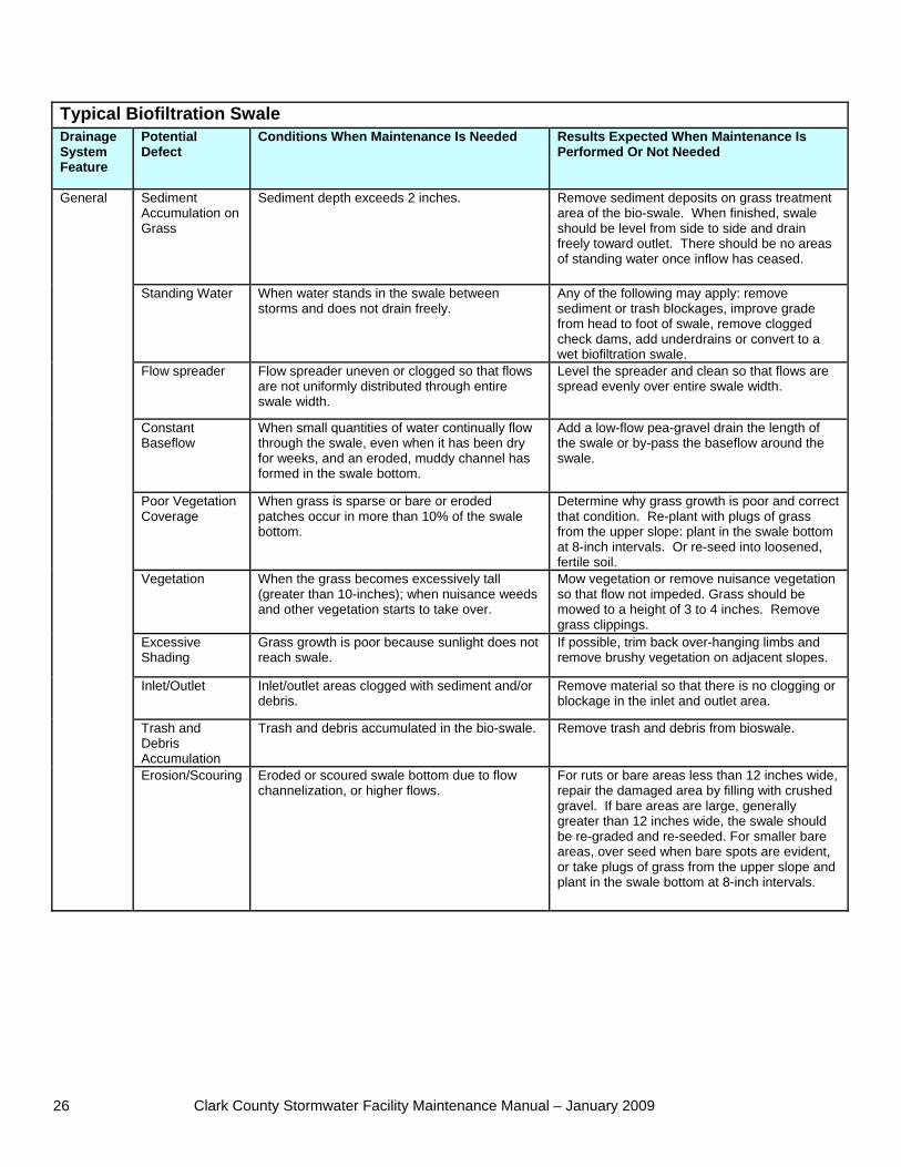
Typical Biofiltration Swale Drainage System Feature
Potential Defect
Conditions When Maintenance Is Needed Results Expected When Maintenance Is Performed Or Not Needed
Sediment Accumulation on Grass
Sediment depth exceeds 2 inches. Remove sediment deposits on grass treatment area of the bio-swale. When finished, swale should be level from side to side and drain freely toward outlet. There should be no areas of standing water once inflow has ceased.
Standing Water When water stands in the swale between storms and does not drain freely.
Any of the following may apply: remove sediment or trash blockages, improve grade from head to foot of swale, remove clogged check dams, add underdrains or convert to a wet biofiltration swale.
Flow spreader Flow spreader uneven or clogged so that flows are not uniformly distributed through entire swale width.
Level the spreader and clean so that flows are spread evenly over entire swale width.
Constant Baseflow
When small quantities of water continually flow through the swale, even when it has been dry for weeks, and an eroded, muddy channel has formed in the swale bottom.
Add a low-flow pea-gravel drain the length of the swale or by-pass the baseflow around the swale.
Poor Vegetation Coverage
When grass is sparse or bare or eroded patches occur in more than 10% of the swale bottom.
Determine why grass growth is poor and correct that condition. Re-plant with plugs of grass from the upper slope: plant in the swale bottom at 8-inch intervals. Or re-seed into loosened, fertile soil.
Vegetation When the grass becomes excessively tall (greater than 10-inches); when nuisance weeds and other vegetation starts to take over.
Mow vegetation or remove nuisance vegetation so that flow not impeded. Grass should be mowed to a height of 3 to 4 inches. Remove grass clippings.
Excessive Shading
Grass growth is poor because sunlight does not reach swale.
If possible, trim back over-hanging limbs and remove brushy vegetation on adjacent slopes.
Inlet/Outlet Inlet/outlet areas clogged with sediment and/or debris.
Remove material so that there is no clogging or blockage in the inlet and outlet area.
Trash and Debris Accumulation
Trash and debris accumulated in the bio-swale. Remove trash and debris from bioswale.
General
Erosion/Scouring Eroded or scoured swale bottom due to flow channelization, or higher flows.
For ruts or bare areas less than 12 inches wide, repair the damaged area by filling with crushed gravel. If bare areas are large, generally greater than 12 inches wide, the swale should be re-graded and re-seeded. For smaller bare areas, over seed when bare spots are evident, or take plugs of grass from the upper slope and plant in the swale bottom at 8-inch intervals.
Clark County Stormwater Facility Maintenance Manual – January 2009 27
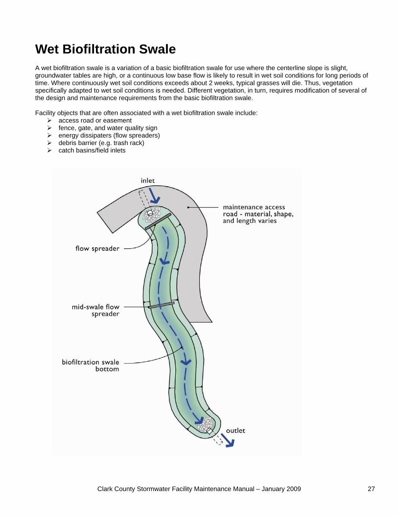
Wet Biofiltration Swale A wet biofiltration swale is a variation of a basic biofiltration swale for use where the centerline slope is slight, groundwater tables are high, or a continuous low base flow is likely to result in wet soil conditions for long periods of time. Where continuously wet soil conditions exceeds about 2 weeks, typical grasses will die. Thus, vegetation specifically adapted to wet soil conditions is needed. Different vegetation, in turn, requires modification of several of the design and maintenance requirements from the basic biofiltration swale. Facility objects that are often associated with a wet biofiltration swale include:
access road or easement fence, gate, and water quality sign energy dissipaters (flow spreaders) debris barrier (e.g. trash rack) catch basins/field inlets
Clark County Stormwater Facility Maintenance Manual – January 2009 28
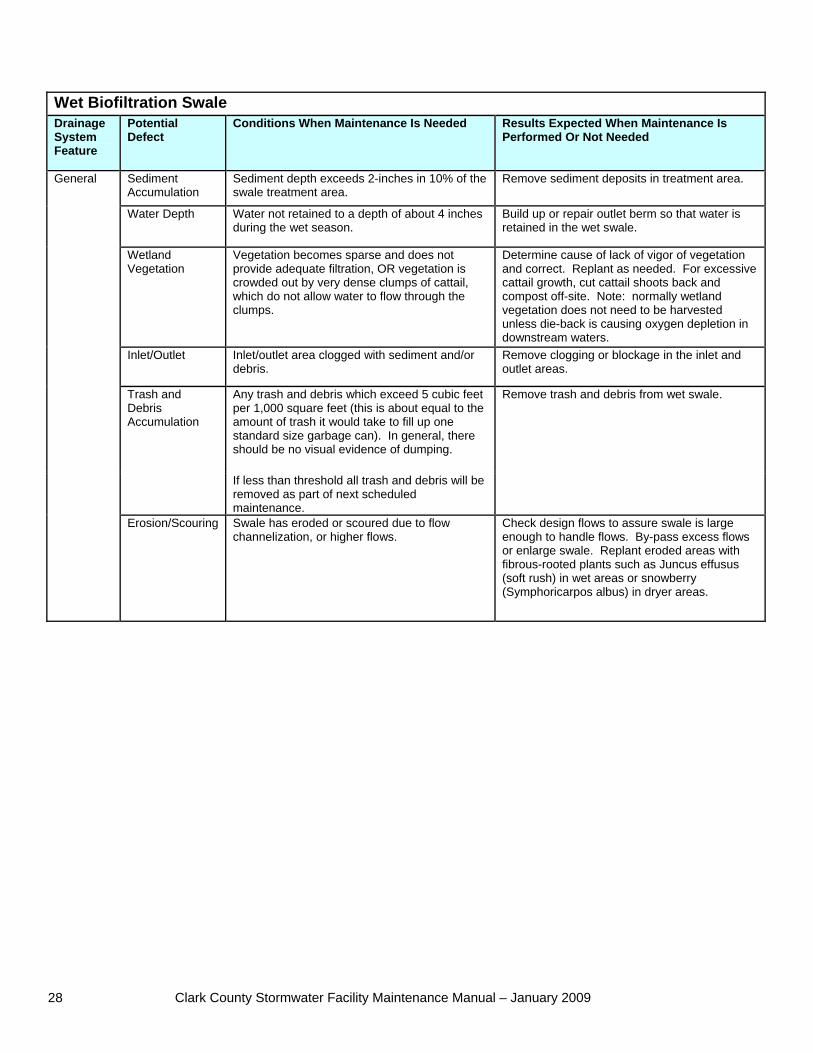
Wet Biofiltration Swale Drainage System Feature
Potential Defect
Conditions When Maintenance Is Needed Results Expected When Maintenance Is Performed Or Not Needed
Sediment Accumulation
Sediment depth exceeds 2-inches in 10% of the swale treatment area.
Remove sediment deposits in treatment area.
Water Depth Water not retained to a depth of about 4 inches during the wet season.
Build up or repair outlet berm so that water is retained in the wet swale.
Wetland Vegetation
Vegetation becomes sparse and does not provide adequate filtration, OR vegetation is crowded out by very dense clumps of cattail, which do not allow water to flow through the clumps.
Determine cause of lack of vigor of vegetation and correct. Replant as needed. For excessive cattail growth, cut cattail shoots back and compost off-site. Note: normally wetland vegetation does not need to be harvested unless die-back is causing oxygen depletion in downstream waters.
Inlet/Outlet Inlet/outlet area clogged with sediment and/or debris.
Remove clogging or blockage in the inlet and outlet areas.
Any trash and debris which exceed 5 cubic feet per 1,000 square feet (this is about equal to the amount of trash it would take to fill up one standard size garbage can). In general, there should be no visual evidence of dumping.
Trash and Debris Accumulation
If less than threshold all trash and debris will be removed as part of next scheduled maintenance.
Remove trash and debris from wet swale.
General
Erosion/Scouring Swale has eroded or scoured due to flow channelization, or higher flows.
Check design flows to assure swale is large enough to handle flows. By-pass excess flows or enlarge swale. Replant eroded areas with fibrous-rooted plants such as Juncus effusus (soft rush) in wet areas or snowberry (Symphoricarpos albus) in dryer areas.
Clark County Stormwater Facility Maintenance Manual – January 2009 29
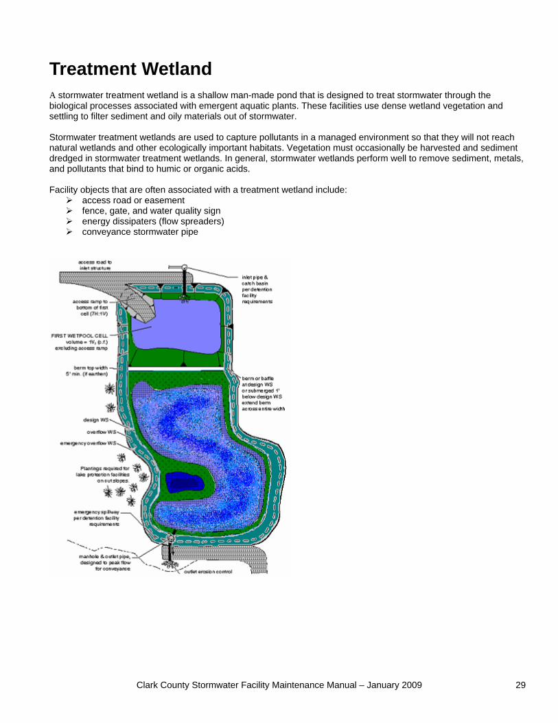
Treatment Wetland A stormwater treatment wetland is a shallow man-made pond that is designed to treat stormwater through the biological processes associated with emergent aquatic plants. These facilities use dense wetland vegetation and settling to filter sediment and oily materials out of stormwater. Stormwater treatment wetlands are used to capture pollutants in a managed environment so that they will not reach natural wetlands and other ecologically important habitats. Vegetation must occasionally be harvested and sediment dredged in stormwater treatment wetlands. In general, stormwater wetlands perform well to remove sediment, metals, and pollutants that bind to humic or organic acids. Facility objects that are often associated with a treatment wetland include:
access road or easement fence, gate, and water quality sign energy dissipaters (flow spreaders) conveyance stormwater pipe
Clark County Stormwater Facility Maintenance Manual – January 2009 30
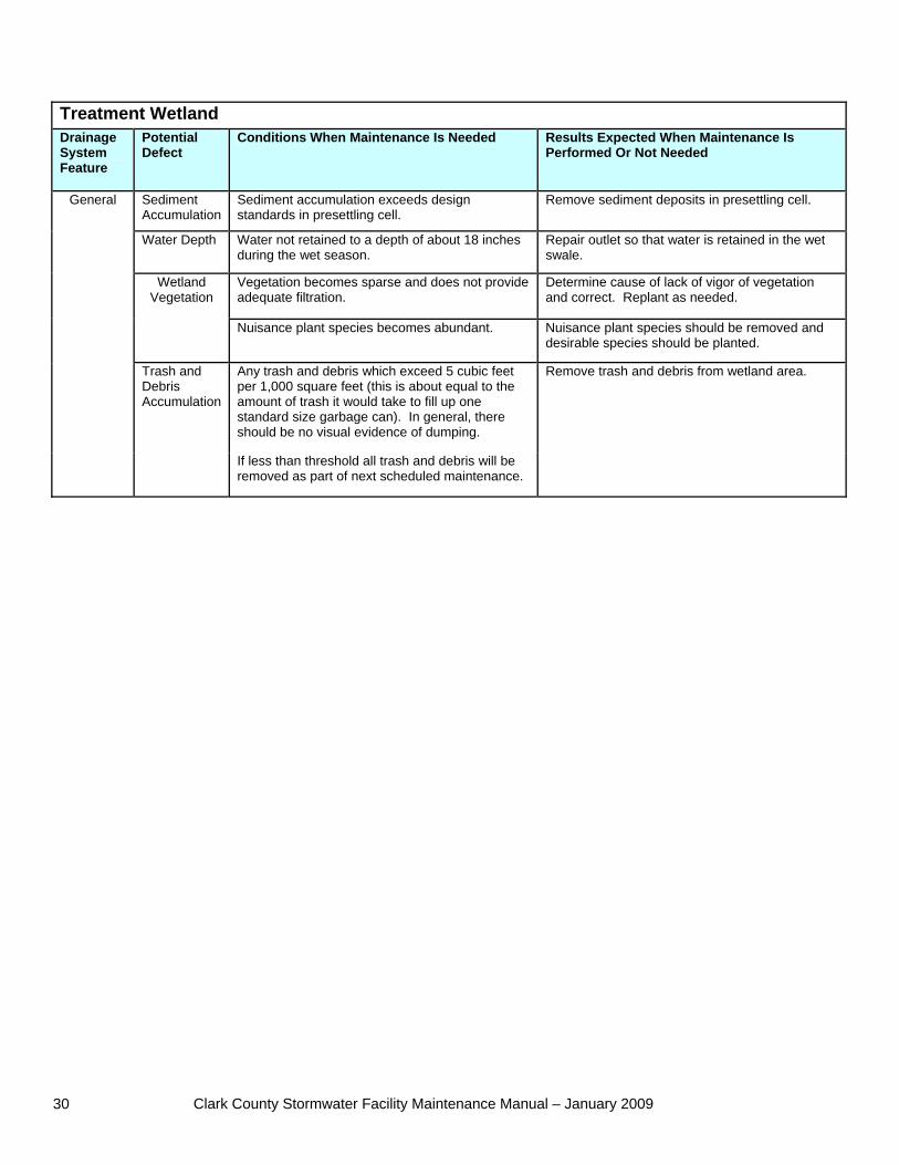
Treatment Wetland Drainage System Feature
Potential Defect
Conditions When Maintenance Is Needed Results Expected When Maintenance Is Performed Or Not Needed
Sediment Accumulation
Sediment accumulation exceeds design standards in presettling cell.
Remove sediment deposits in presettling cell.
Water Depth Water not retained to a depth of about 18 inches during the wet season.
Repair outlet so that water is retained in the wet swale.
Vegetation becomes sparse and does not provide adequate filtration.
Determine cause of lack of vigor of vegetation and correct. Replant as needed.
Wetland Vegetation
Nuisance plant species becomes abundant. Nuisance plant species should be removed and desirable species should be planted.
Any trash and debris which exceed 5 cubic feet per 1,000 square feet (this is about equal to the amount of trash it would take to fill up one standard size garbage can). In general, there should be no visual evidence of dumping.
General
Trash and Debris Accumulation
If less than threshold all trash and debris will be removed as part of next scheduled maintenance.
Remove trash and debris from wetland area.
Clark County Stormwater Facility Maintenance Manual – January 2009 31
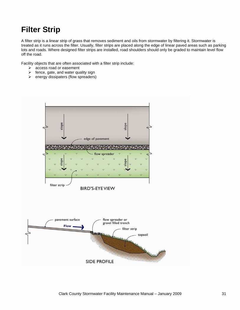
Filter Strip A filter strip is a linear strip of grass that removes sediment and oils from stormwater by filtering it. Stormwater is treated as it runs across the filter. Usually, filter strips are placed along the edge of linear paved areas such as parking lots and roads. Where designed filter strips are installed, road shoulders should only be graded to maintain level flow off the road. Facility objects that are often associated with a filter strip include:
access road or easement fence, gate, and water quality sign energy dissipaters (flow spreaders)
Clark County Stormwater Facility Maintenance Manual – January 2009 32
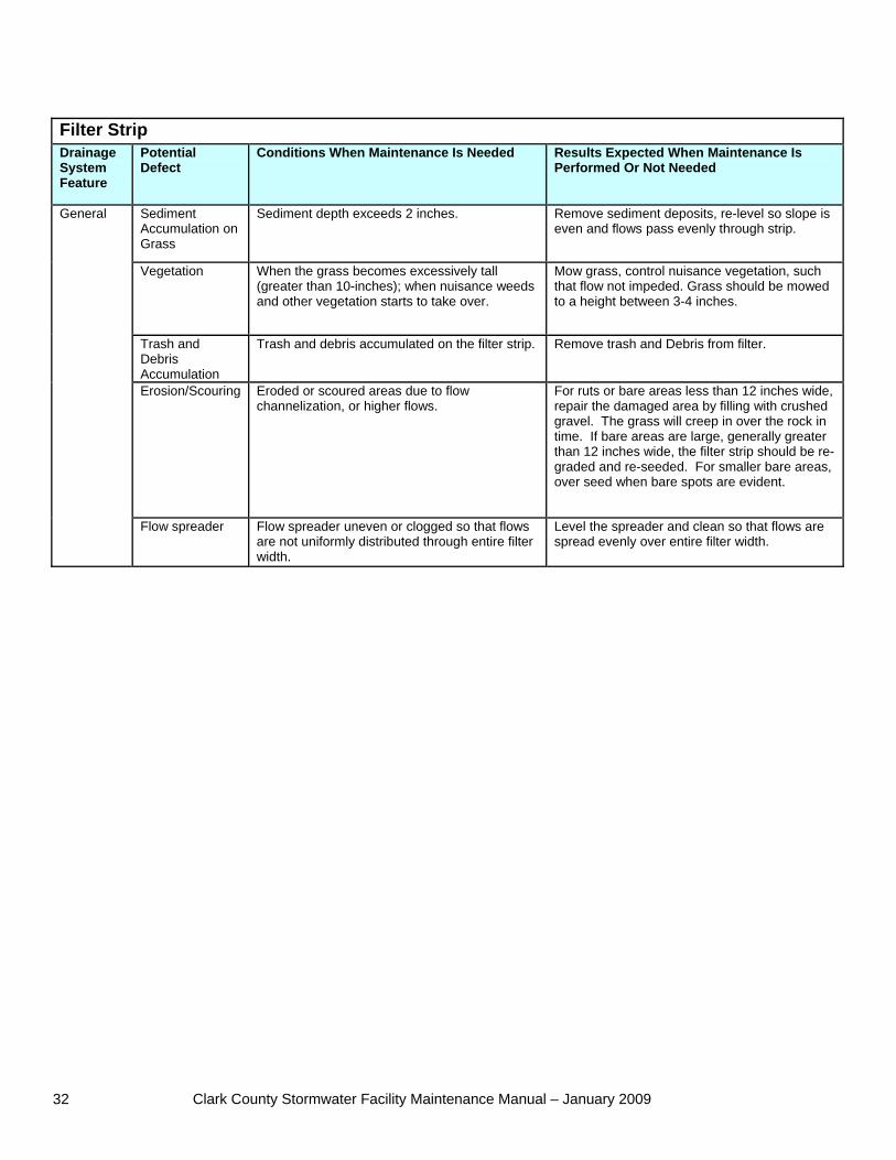
Filter Strip Drainage System Feature
Potential Defect
Conditions When Maintenance Is Needed Results Expected When Maintenance Is Performed Or Not Needed
Sediment Accumulation on Grass
Sediment depth exceeds 2 inches. Remove sediment deposits, re-level so slope is even and flows pass evenly through strip.
Vegetation When the grass becomes excessively tall (greater than 10-inches); when nuisance weeds and other vegetation starts to take over.
Mow grass, control nuisance vegetation, such that flow not impeded. Grass should be mowed to a height between 3-4 inches.
Trash and Debris Accumulation
Trash and debris accumulated on the filter strip. Remove trash and Debris from filter.
Erosion/Scouring Eroded or scoured areas due to flow channelization, or higher flows.
For ruts or bare areas less than 12 inches wide, repair the damaged area by filling with crushed gravel. The grass will creep in over the rock in time. If bare areas are large, generally greater than 12 inches wide, the filter strip should be re-graded and re-seeded. For smaller bare areas, over seed when bare spots are evident.
General
Flow spreader Flow spreader uneven or clogged so that flows are not uniformly distributed through entire filter width.
Level the spreader and clean so that flows are spread evenly over entire filter width.
Clark County Stormwater Facility Maintenance Manual – January 2009 33
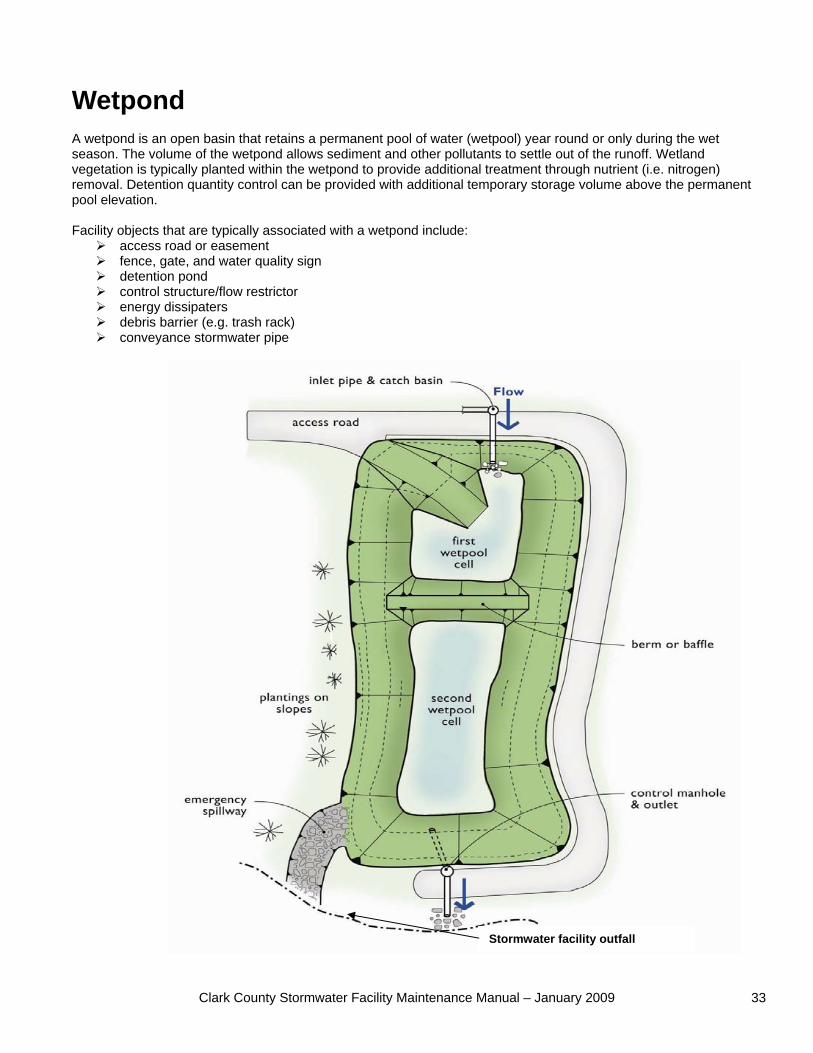
Wetpond A wetpond is an open basin that retains a permanent pool of water (wetpool) year round or only during the wet season. The volume of the wetpond allows sediment and other pollutants to settle out of the runoff. Wetland vegetation is typically planted within the wetpond to provide additional treatment through nutrient (i.e. nitrogen) removal. Detention quantity control can be provided with additional temporary storage volume above the permanent pool elevation. Facility objects that are typically associated with a wetpond include:
access road or easement fence, gate, and water quality sign detention pond control structure/flow restrictor energy dissipaters debris barrier (e.g. trash rack) conveyance stormwater pipe
Stormwater facility outfall
Clark County Stormwater Facility Maintenance Manual – January 2009 34
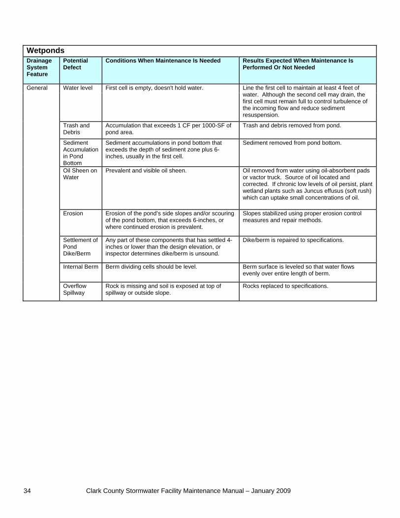
Wetponds Drainage System Feature
Potential Defect
Conditions When Maintenance Is Needed Results Expected When Maintenance Is Performed Or Not Needed
Water level First cell is empty, doesn't hold water. Line the first cell to maintain at least 4 feet of water. Although the second cell may drain, the first cell must remain full to control turbulence of the incoming flow and reduce sediment resuspension.
Trash and Debris
Accumulation that exceeds 1 CF per 1000-SF of pond area.
Trash and debris removed from pond.
Sediment Accumulation in Pond Bottom
Sediment accumulations in pond bottom that exceeds the depth of sediment zone plus 6-inches, usually in the first cell.
Sediment removed from pond bottom.
Oil Sheen on Water
Prevalent and visible oil sheen. Oil removed from water using oil-absorbent pads or vactor truck. Source of oil located and corrected. If chronic low levels of oil persist, plant wetland plants such as Juncus effusus (soft rush) which can uptake small concentrations of oil.
Erosion Erosion of the pond’s side slopes and/or scouring of the pond bottom, that exceeds 6-inches, or where continued erosion is prevalent.
Slopes stabilized using proper erosion control measures and repair methods.
Settlement of Pond Dike/Berm
Any part of these components that has settled 4-inches or lower than the design elevation, or inspector determines dike/berm is unsound.
Dike/berm is repaired to specifications.
Internal Berm Berm dividing cells should be level. Berm surface is leveled so that water flows evenly over entire length of berm.
General
Overflow Spillway
Rock is missing and soil is exposed at top of spillway or outside slope.
Rocks replaced to specifications.
Clark County Stormwater Facility Maintenance Manual – January 2009 35
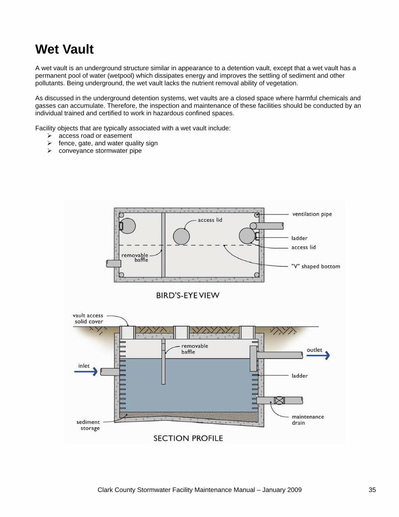
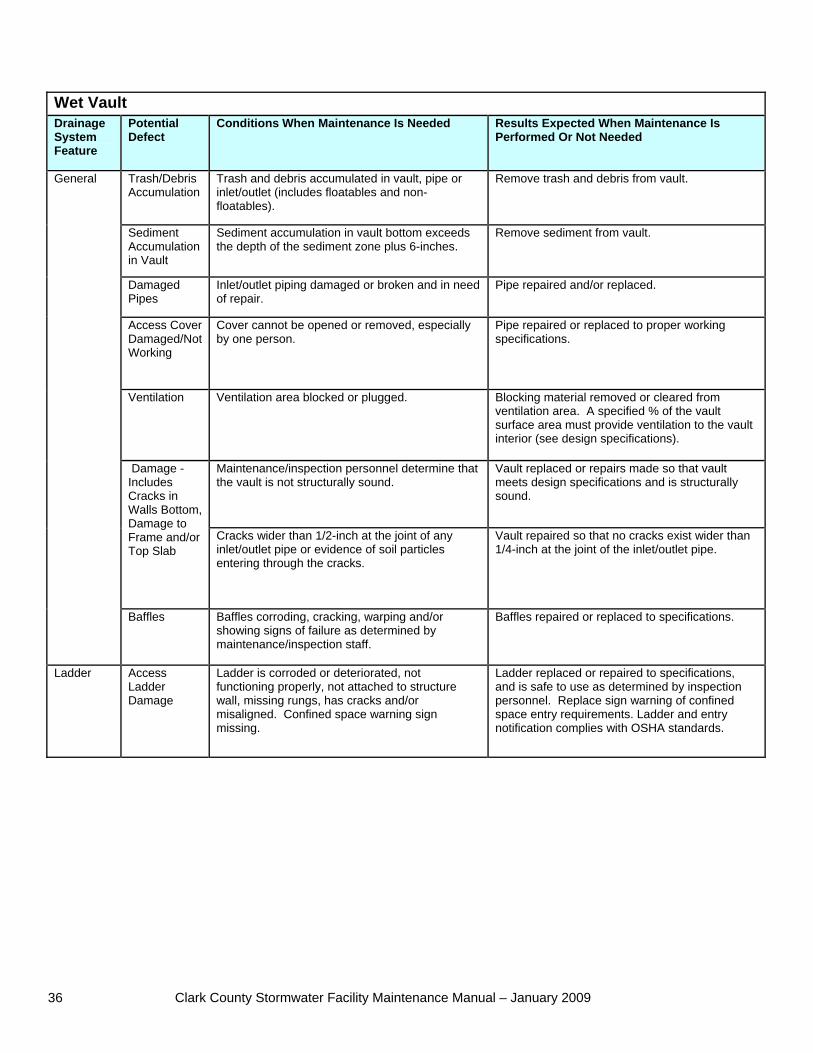
Wet Vault A wet vault is an underground structure similar in appearance to a detention vault, except that a wet vault has a permanent pool of water (wetpool) which dissipates energy and improves the settling of sediment and other pollutants. Being underground, the wet vault lacks the nutrient removal ability of vegetation. As discussed in the underground detention systems, wet vaults are a closed space where harmful chemicals and gasses can accumulate. Therefore, the inspection and maintenance of these facilities should be conducted by an individual trained and certified to work in hazardous confined spaces. Facility objects that are typically associated with a wet vault include:
access road or easement fence, gate, and water quality sign conveyance stormwater pipe
Clark County Stormwater Facility Maintenance Manual – January 2009 36
Wet Vault Drainage System Feature
Potential Defect
Conditions When Maintenance Is Needed Results Expected When Maintenance Is Performed Or Not Needed
Trash/Debris Accumulation
Trash and debris accumulated in vault, pipe or inlet/outlet (includes floatables and non-floatables).
Remove trash and debris from vault.
Sediment Accumulation in Vault
Sediment accumulation in vault bottom exceeds the depth of the sediment zone plus 6-inches.
Remove sediment from vault.
Damaged Pipes
Inlet/outlet piping damaged or broken and in need of repair.
Pipe repaired and/or replaced.
Access Cover Damaged/Not Working
Cover cannot be opened or removed, especially by one person.
Pipe repaired or replaced to proper working specifications.
Ventilation Ventilation area blocked or plugged. Blocking material removed or cleared from ventilation area. A specified % of the vault surface area must provide ventilation to the vault interior (see design specifications).
Maintenance/inspection personnel determine that the vault is not structurally sound.
Vault replaced or repairs made so that vault meets design specifications and is structurally sound.
Damage - Includes Cracks in Walls Bottom, Damage to Frame and/or Top Slab
Cracks wider than 1/2-inch at the joint of any inlet/outlet pipe or evidence of soil particles entering through the cracks.
Vault repaired so that no cracks exist wider than 1/4-inch at the joint of the inlet/outlet pipe.
General
Baffles Baffles corroding, cracking, warping and/or showing signs of failure as determined by maintenance/inspection staff.
Baffles repaired or replaced to specifications.
Ladder Access Ladder Damage
Ladder is corroded or deteriorated, not functioning properly, not attached to structure wall, missing rungs, has cracks and/or misaligned. Confined space warning sign missing.
Ladder replaced or repaired to specifications, and is safe to use as determined by inspection personnel. Replace sign warning of confined space entry requirements. Ladder and entry notification complies with OSHA standards.
Clark County Stormwater Facility Maintenance Manual – January 2009 37
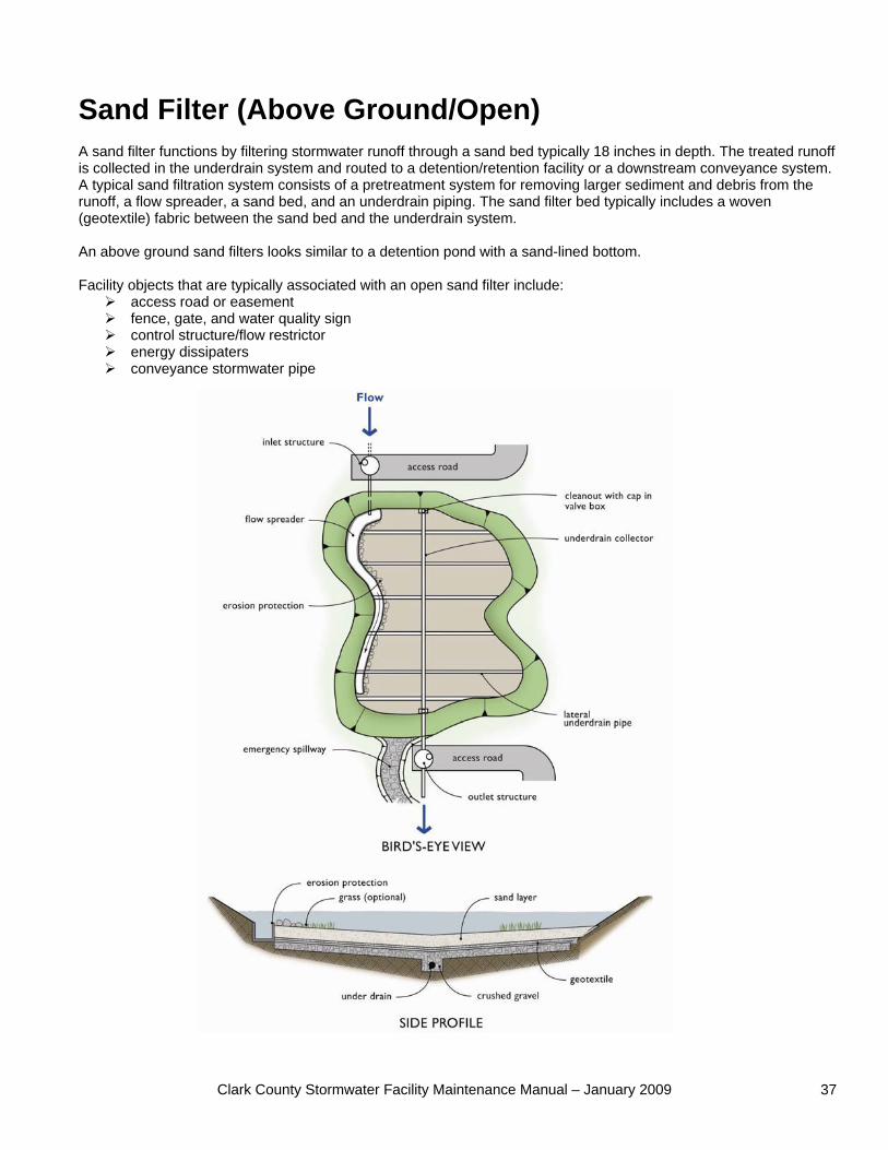
Sand Filter (Above Ground/Open) A sand filter functions by filtering stormwater runoff through a sand bed typically 18 inches in depth. The treated runoff is collected in the underdrain system and routed to a detention/retention facility or a downstream conveyance system. A typical sand filtration system consists of a pretreatment system for removing larger sediment and debris from the runoff, a flow spreader, a sand bed, and an underdrain piping. The sand filter bed typically includes a woven (geotextile) fabric between the sand bed and the underdrain system. An above ground sand filters looks similar to a detention pond with a sand-lined bottom. Facility objects that are typically associated with an open sand filter include:
access road or easement fence, gate, and water quality sign control structure/flow restrictor energy dissipaters conveyance stormwater pipe
Clark County Stormwater Facility Maintenance Manual – January 2009 38
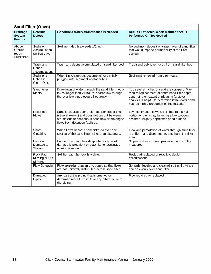
Sand Filter (Open) Drainage System Feature
Potential Defect
Conditions When Maintenance Is Needed Results Expected When Maintenance Is Performed Or Not Needed
Sediment Accumulation on Top Layer
Sediment depth exceeds 1/2-inch. No sediment deposit on grass layer of sand filter that would impede permeability of the filter section.
Trash and Debris Accumulations
Trash and debris accumulated on sand filter bed. Trash and debris removed from sand filter bed.
Sediment/ Debris in Clean-Outs
When the clean-outs become full or partially plugged with sediment and/or debris.
Sediment removed from clean-outs.
Sand Filter Media
Drawdown of water through the sand filter media takes longer than 24-hours, and/or flow through the overflow pipes occurs frequently.
Top several inches of sand are scraped. May require replacement of entire sand filter depth depending on extent of plugging (a sieve analysis is helpful to determine if the lower sand has too high a proportion of fine material).
Prolonged Flows
Sand is saturated for prolonged periods of time (several weeks) and does not dry out between storms due to continuous base flow or prolonged flows from detention facilities.
Low, continuous flows are limited to a small portion of the facility by using a low wooden divider or slightly depressed sand surface.
Short Circuiting
When flows become concentrated over one section of the sand filter rather than dispersed.
Flow and percolation of water through sand filter is uniform and dispersed across the entire filter area.
Erosion Damage to Slopes
Erosion over 2-inches deep where cause of damage is prevalent or potential for continued erosion is evident.
Slopes stabilized using proper erosion control measures.
Rock Pad Missing or Out of Place
Soil beneath the rock is visible. Rock pad replaced or rebuilt to design specifications.
Flow Spreader Flow spreader uneven or clogged so that flows are not uniformly distributed across sand filter.
Spreader leveled and cleaned so that flows are spread evenly over sand filter.
Above Ground (open sand filter)
Damaged Pipes
Any part of the piping that is crushed or deformed more than 20% or any other failure to the piping.
Pipe repaired or replaced.
Clark County Stormwater Facility Maintenance Manual – January 2009 39
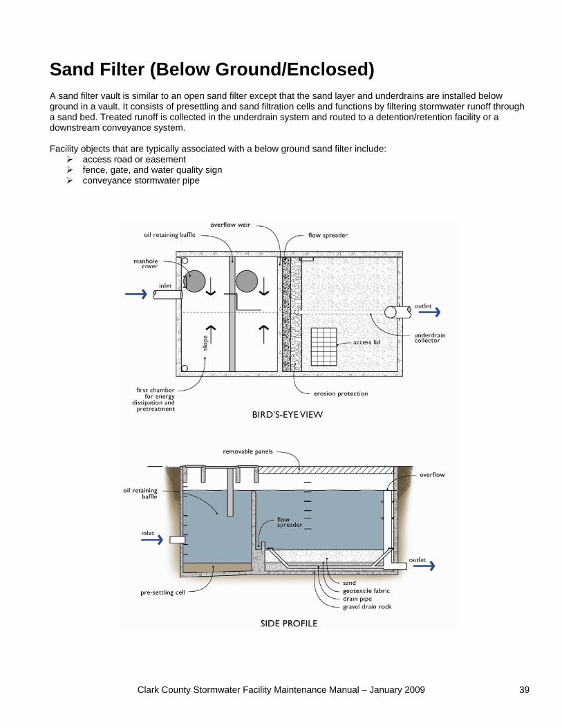
Sand Filter (Below Ground/Enclosed) A sand filter vault is similar to an open sand filter except that the sand layer and underdrains are installed below ground in a vault. It consists of presettling and sand filtration cells and functions by filtering stormwater runoff through a sand bed. Treated runoff is collected in the underdrain system and routed to a detention/retention facility or a downstream conveyance system. Facility objects that are typically associated with a below ground sand filter include:
access road or easement fence, gate, and water quality sign conveyance stormwater pipe
Clark County Stormwater Facility Maintenance Manual – January 2009 40
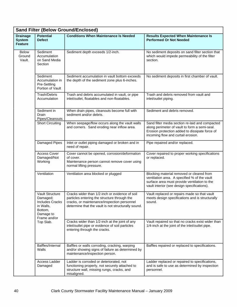
Sand Filter (Below Ground/Enclosed) Drainage System Feature
Potential Defect
Conditions When Maintenance Is Needed Results Expected When Maintenance Is Performed Or Not Needed
Sediment Accumulation on Sand Media Section
Sediment depth exceeds 1/2-inch. No sediment deposits on sand filter section that which would impede permeability of the filter section.
Sediment Accumulation in Pre-Settling Portion of Vault
Sediment accumulation in vault bottom exceeds the depth of the sediment zone plus 6-inches.
No sediment deposits in first chamber of vault.
Trash/Debris Accumulation
Trash and debris accumulated in vault, or pipe inlet/outlet, floatables and non-floatables.
Trash and debris removed from vault and inlet/outlet piping.
Sediment in Drain Pipes/Cleanouts
When drain pipes, cleanouts become full with sediment and/or debris.
Sediment and debris removed.
Short Circuiting When seepage/flow occurs along the vault walls and corners. Sand eroding near inflow area.
Sand filter media section re-laid and compacted along perimeter of vault to form a semi-seal. Erosion protection added to dissipate force of incoming flow and curtail erosion.
Damaged Pipes Inlet or outlet piping damaged or broken and in need of repair.
Pipe repaired and/or replaced.
Access Cover Damaged/Not Working
Cover cannot be opened, corrosion/deformation of cover. Maintenance person cannot remove cover using normal lifting pressure.
Cover repaired to proper working specifications or replaced.
Ventilation Ventilation area blocked or plugged Blocking material removed or cleared from ventilation area. A specified % of the vault surface area must provide ventilation to the vault interior (see design specifications).
Cracks wider than 1/2-inch or evidence of soil particles entering the structure through the cracks, or maintenance/inspection personnel determine that the vault is not structurally sound.
Vault replaced or repairs made so that vault meets design specifications and is structurally sound.
Vault Structure Damaged; Includes Cracks in Walls, Bottom, Damage to Frame and/or Top Slab. Cracks wider than 1/2-inch at the joint of any
inlet/outlet pipe or evidence of soil particles entering through the cracks.
Vault repaired so that no cracks exist wider than 1/4-inch at the joint of the inlet/outlet pipe.
Baffles/Internal Walls
Baffles or walls corroding, cracking, warping and/or showing signs of failure as determined by maintenance/inspection person.
Baffles repaired or replaced to specifications.
Below Ground Vault.
Access Ladder Damaged
Ladder is corroded or deteriorated, not functioning properly, not securely attached to structure wall, missing rungs, cracks, and misaligned.
Ladder replaced or repaired to specifications, and is safe to use as determined by inspection personnel.
Clark County Stormwater Facility Maintenance Manual – January 2009 41
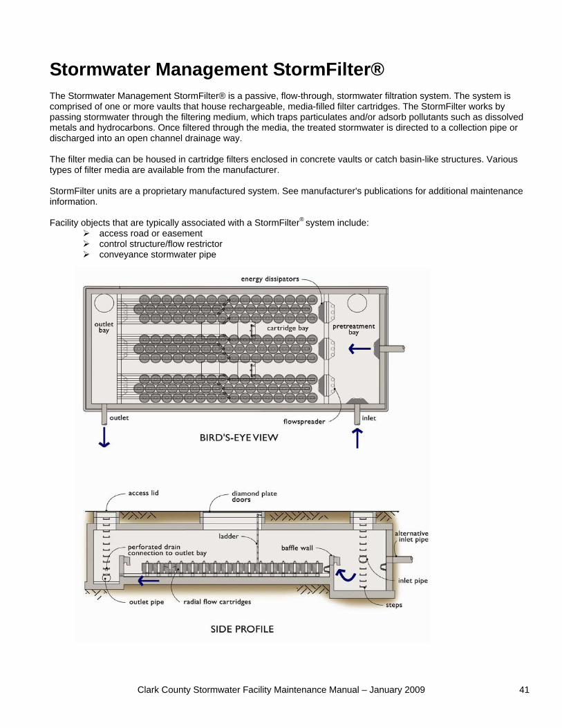
Stormwater Management StormFilter® The Stormwater Management StormFilter® is a passive, flow-through, stormwater filtration system. The system is comprised of one or more vaults that house rechargeable, media-filled filter cartridges. The StormFilter works by passing stormwater through the filtering medium, which traps particulates and/or adsorb pollutants such as dissolved metals and hydrocarbons. Once filtered through the media, the treated stormwater is directed to a collection pipe or discharged into an open channel drainage way. The filter media can be housed in cartridge filters enclosed in concrete vaults or catch basin-like structures. Various types of filter media are available from the manufacturer. StormFilter units are a proprietary manufactured system. See manufacturer's publications for additional maintenance information. Facility objects that are typically associated with a StormFilter® system include:
access road or easement control structure/flow restrictor conveyance stormwater pipe
Clark County Stormwater Facility Maintenance Manual – January 2009 42
StormFilter® (leaf compost filter) Drainage System Feature
Potential Defect
Conditions When Maintenance Is Needed Results Expected When Maintenance Is Performed Or Not Needed
Fore bay Sediment Accumulation
Sediment accumulation exceeds 6 inches or 1/3 of available sump.
Sediment accumulation less than 6 inches.
Media Filter Vault
Sediment Accumulation on Top of Filter Cartridges.
Sediment depth exceeds 0.25-inches on top of filter cartridges.
No sediment deposits on top of cartridges. Sediment on cartridges likely indicates that cartridges are plugged and require maintenance. No sediment deposits which would impede permeability of the compost media.
Sediment Accumulation in Vault
Sediment depth exceeds 4 inches in first chamber. Look for other indicators of clogged cartridges or overflow.
Sediment in vault should be removed. Cartridges should be checked and replaced or serviced as needed. No sediment deposits in vault bottom of first chamber.
Trash and Floatable Debris Accumulation
Trash and floatable debris accumulated in vault. No trash or floatable debris in filter vault.
Sediment in Drain Pipes/Clean-Outs
When drain pipes, clean-outs, become full with sediment and/or debris.
Sediment and debris removed.
Damaged Pipes
Any part of the pipes that are crushed or damaged due to corrosion and/or settlement.
Pipe repaired and/or replaced.
Access Cover Damaged/Not Working
Cover cannot be opened; one person cannot open the cover using normal lifting pressure, corrosion/deformation of cover.
Cover repaired to proper working specifications or replaced.
Cracks wider than 1/2-inch or evidence of soil particles entering the structure through the cracks, or maintenance/inspection personnel determine that the vault is not structurally sound.
Vault replaced or repairs made so that vault meets design specifications and is structurally sound.
Vault Structure Includes Cracks in Wall, Bottom, Damage to Frame and/or Top Slab
Cracks wider than 1/2-inch at the joint of any inlet/outlet pipe or evidence of soil particles entering through the cracks.
Vault repaired so that no cracks exist wider than 1/4-inch at the joint of the inlet/outlet pipe.
Baffles Baffles corroding, cracking warping, and/or showing signs of failure as determined by maintenance/inspection person.
Baffles repaired or replaced to specifications.
Access Ladder Damaged
Ladder is corroded or deteriorated, not functioning properly, not securely attached to structure wall, missing rungs, cracks, and misaligned.
Ladder replaced or repaired and meets specifications, and is safe to use as determined by inspection personnel.
Compost Media
Drawdown of water through the media takes longer than 1 hour, and/or overflow occurs frequently.
Media cartridges replaced.
Short Circuiting
Flows do not properly enter filter cartridges. Filter cartridges replaced.
Below Ground Cartridge Type
Filter cartridges Submerged.
Filter vault does not drain within 24 hours following storm. Look for evidence of submergence due to backwater or excessive hydrocarbon loading.
Filter media checked and replaced if needed. If cartridges are plugged with oil, additional treatment or source control BMP may be needed.
Clark County Stormwater Facility Maintenance Manual – January 2009 43
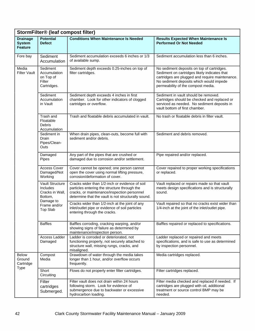
Oil/Water Separator (API Type) An oil/water separator is an underground vault that treats stormwater by mechanically separating oil from water. The oil rises to the surface and floats on the water and sediment settles to the bottom. Oil/water separators are typically utilized in locations where high oil concentrations in the stormwater runoff are anticipated (e.g. service and fuel stations). Oil/water separators are most commonly used as the first pre-treatment facility in a series of stormwater management facilities. Facility objects that are typically associated with an oil/water separator include:
access road or easement control structure/flow restrictor
Clark County Stormwater Facility Maintenance Manual – January 2009 44
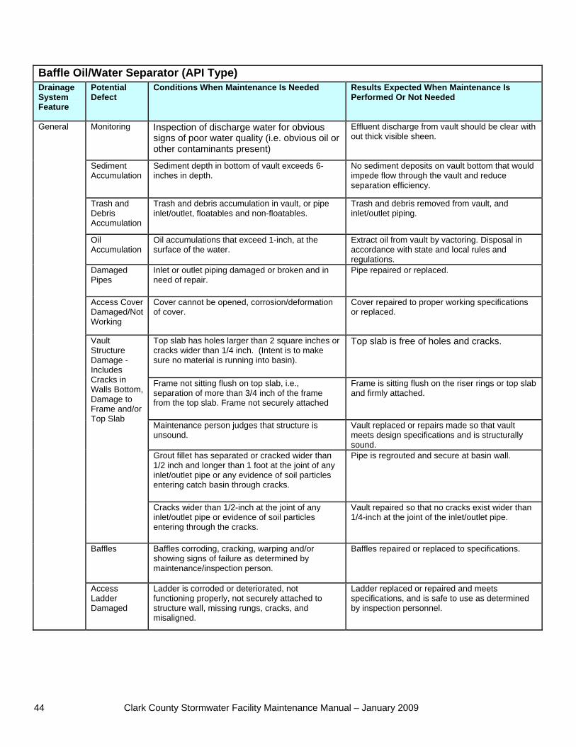
Baffle Oil/Water Separator (API Type) Drainage System Feature
Potential Defect
Conditions When Maintenance Is Needed Results Expected When Maintenance Is Performed Or Not Needed
Monitoring Inspection of discharge water for obvious signs of poor water quality (i.e. obvious oil or other contaminants present)
Effluent discharge from vault should be clear with out thick visible sheen.
Sediment Accumulation
Sediment depth in bottom of vault exceeds 6-inches in depth.
No sediment deposits on vault bottom that would impede flow through the vault and reduce separation efficiency.
Trash and Debris Accumulation
Trash and debris accumulation in vault, or pipe inlet/outlet, floatables and non-floatables.
Trash and debris removed from vault, and inlet/outlet piping.
Oil Accumulation
Oil accumulations that exceed 1-inch, at the surface of the water.
Extract oil from vault by vactoring. Disposal in accordance with state and local rules and regulations.
Damaged Pipes
Inlet or outlet piping damaged or broken and in need of repair.
Pipe repaired or replaced.
Access Cover Damaged/Not Working
Cover cannot be opened, corrosion/deformation of cover.
Cover repaired to proper working specifications or replaced.
Top slab has holes larger than 2 square inches or cracks wider than 1/4 inch. (Intent is to make sure no material is running into basin).
Top slab is free of holes and cracks.
Frame not sitting flush on top slab, i.e., separation of more than 3/4 inch of the frame from the top slab. Frame not securely attached
Frame is sitting flush on the riser rings or top slab and firmly attached.
Maintenance person judges that structure is unsound.
Vault replaced or repairs made so that vault meets design specifications and is structurally sound.
Grout fillet has separated or cracked wider than 1/2 inch and longer than 1 foot at the joint of any inlet/outlet pipe or any evidence of soil particles entering catch basin through cracks.
Pipe is regrouted and secure at basin wall.
Vault Structure Damage - Includes Cracks in Walls Bottom, Damage to Frame and/or Top Slab
Cracks wider than 1/2-inch at the joint of any inlet/outlet pipe or evidence of soil particles entering through the cracks.
Vault repaired so that no cracks exist wider than 1/4-inch at the joint of the inlet/outlet pipe.
Baffles Baffles corroding, cracking, warping and/or showing signs of failure as determined by maintenance/inspection person.
Baffles repaired or replaced to specifications.
General
Access Ladder Damaged
Ladder is corroded or deteriorated, not functioning properly, not securely attached to structure wall, missing rungs, cracks, and misaligned.
Ladder replaced or repaired and meets specifications, and is safe to use as determined by inspection personnel.
Clark County Stormwater Facility Maintenance Manual – January 2009 45
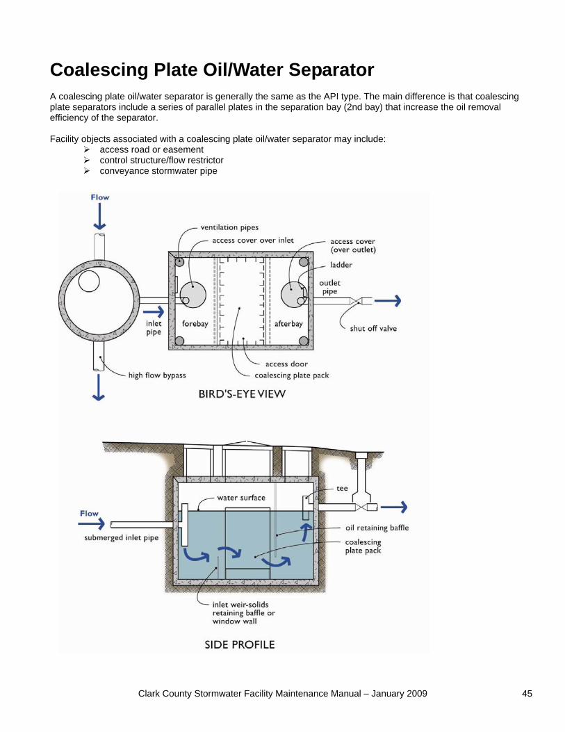
Coalescing Plate Oil/Water Separator A coalescing plate oil/water separator is generally the same as the API type. The main difference is that coalescing plate separators include a series of parallel plates in the separation bay (2nd bay) that increase the oil removal efficiency of the separator. Facility objects associated with a coalescing plate oil/water separator may include:
access road or easement control structure/flow restrictor conveyance stormwater pipe
Clark County Stormwater Facility Maintenance Manual – January 2009 46
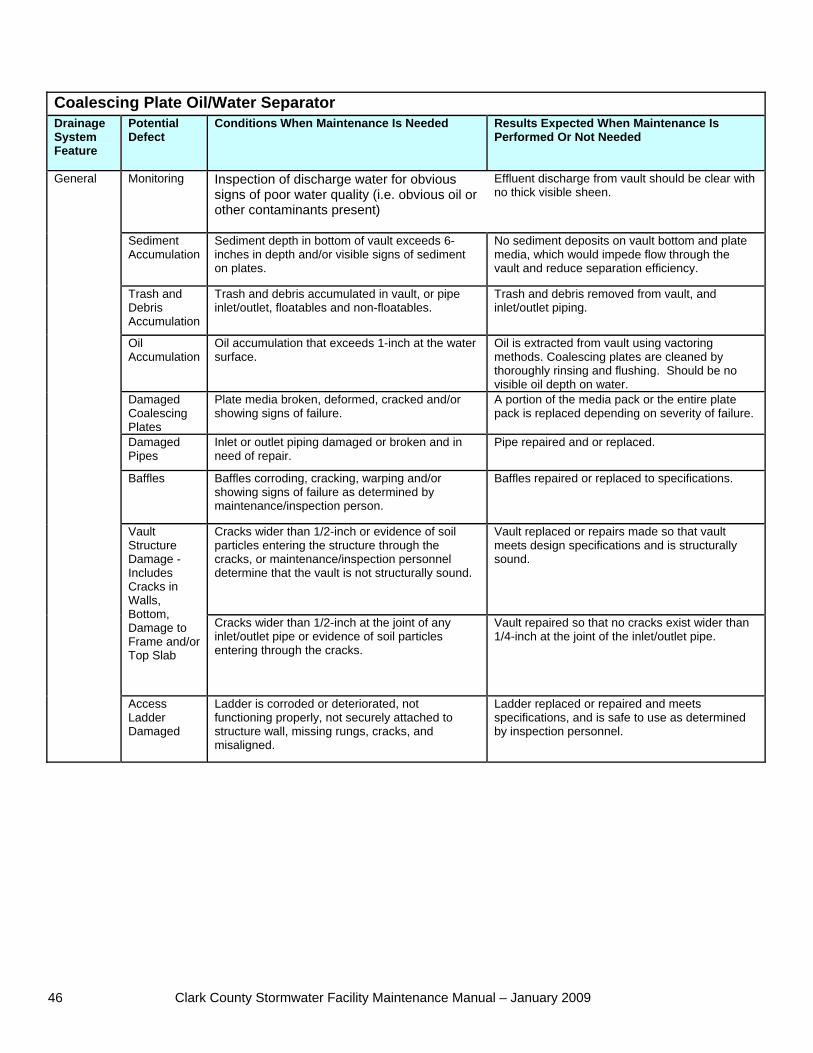
Coalescing Plate Oil/Water Separator Drainage System Feature
Potential Defect
Conditions When Maintenance Is Needed Results Expected When Maintenance Is Performed Or Not Needed
Monitoring Inspection of discharge water for obvious signs of poor water quality (i.e. obvious oil or other contaminants present)
Effluent discharge from vault should be clear with no thick visible sheen.
Sediment Accumulation
Sediment depth in bottom of vault exceeds 6-inches in depth and/or visible signs of sediment on plates.
No sediment deposits on vault bottom and plate media, which would impede flow through the vault and reduce separation efficiency.
Trash and Debris Accumulation
Trash and debris accumulated in vault, or pipe inlet/outlet, floatables and non-floatables.
Trash and debris removed from vault, and inlet/outlet piping.
Oil Accumulation
Oil accumulation that exceeds 1-inch at the water surface.
Oil is extracted from vault using vactoring methods. Coalescing plates are cleaned by thoroughly rinsing and flushing. Should be no visible oil depth on water.
Damaged Coalescing Plates
Plate media broken, deformed, cracked and/or showing signs of failure.
A portion of the media pack or the entire plate pack is replaced depending on severity of failure.
Damaged Pipes
Inlet or outlet piping damaged or broken and in need of repair.
Pipe repaired and or replaced.
Baffles Baffles corroding, cracking, warping and/or showing signs of failure as determined by maintenance/inspection person.
Baffles repaired or replaced to specifications.
Cracks wider than 1/2-inch or evidence of soil particles entering the structure through the cracks, or maintenance/inspection personnel determine that the vault is not structurally sound.
Vault replaced or repairs made so that vault meets design specifications and is structurally sound.
Vault Structure Damage - Includes Cracks in Walls, Bottom, Damage to Frame and/or Top Slab
Cracks wider than 1/2-inch at the joint of any inlet/outlet pipe or evidence of soil particles entering through the cracks.
Vault repaired so that no cracks exist wider than 1/4-inch at the joint of the inlet/outlet pipe.
General
Access Ladder Damaged
Ladder is corroded or deteriorated, not functioning properly, not securely attached to structure wall, missing rungs, cracks, and misaligned.
Ladder replaced or repaired and meets specifications, and is safe to use as determined by inspection personnel.
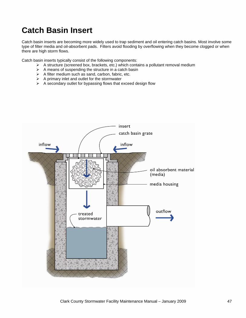
Clark County Stormwater Facility Maintenance Manual – January 2009 47
Catch Basin Insert Catch basin inserts are becoming more widely used to trap sediment and oil entering catch basins. Most involve some type of filter media and oil-absorbent pads. Filters avoid flooding by overflowing when they become clogged or when there are high storm flows. Catch basin inserts typically consist of the following components:
A structure (screened box, brackets, etc.) which contains a pollutant removal medium A means of suspending the structure in a catch basin A filter medium such as sand, carbon, fabric, etc. A primary inlet and outlet for the stormwater A secondary outlet for bypassing flows that exceed design flow
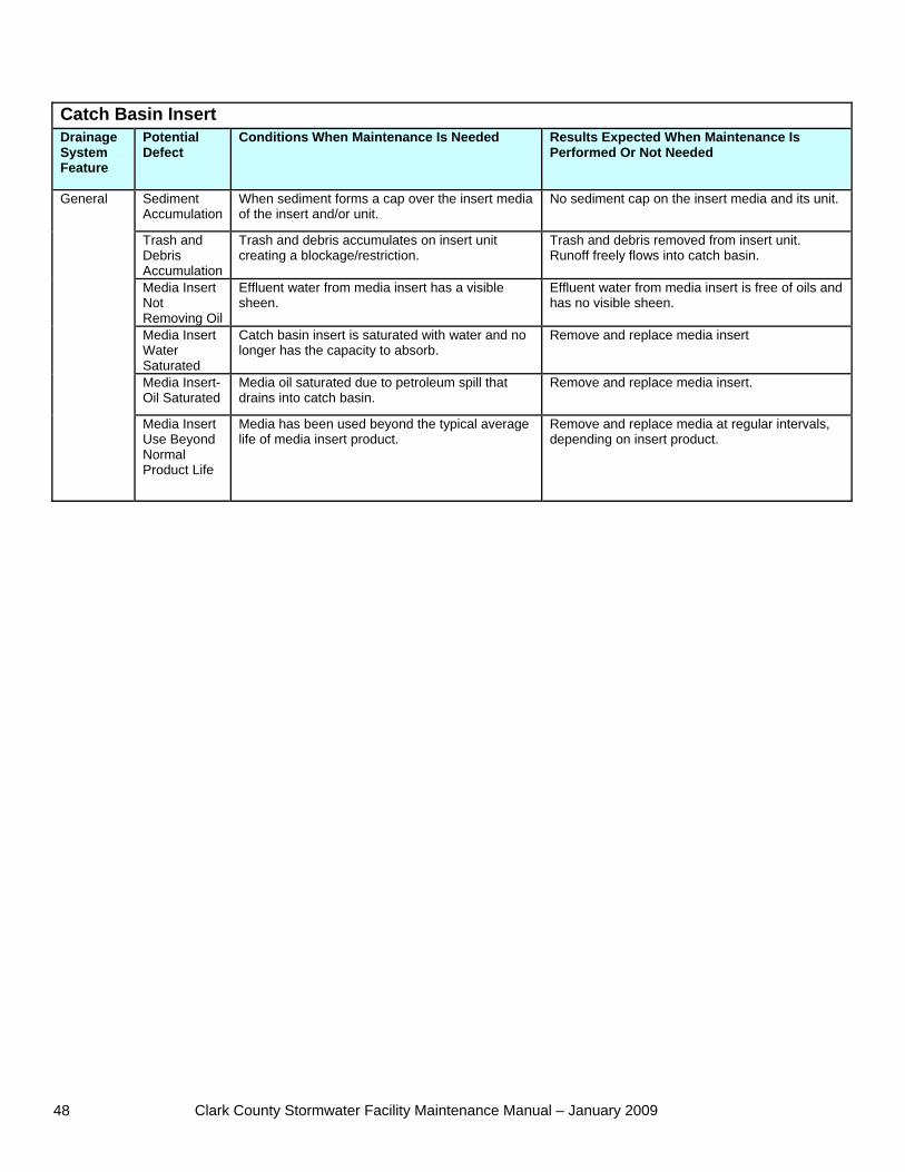
Clark County Stormwater Facility Maintenance Manual – January 2009 48
Catch Basin Insert Drainage System Feature
Potential Defect
Conditions When Maintenance Is Needed Results Expected When Maintenance Is Performed Or Not Needed
Sediment Accumulation
When sediment forms a cap over the insert media of the insert and/or unit.
No sediment cap on the insert media and its unit.
Trash and Debris Accumulation
Trash and debris accumulates on insert unit creating a blockage/restriction.
Trash and debris removed from insert unit. Runoff freely flows into catch basin.
Media Insert Not Removing Oil
Effluent water from media insert has a visible sheen.
Effluent water from media insert is free of oils and has no visible sheen.
Media Insert Water Saturated
Catch basin insert is saturated with water and no longer has the capacity to absorb.
Remove and replace media insert
Media Insert-Oil Saturated
Media oil saturated due to petroleum spill that drains into catch basin.
Remove and replace media insert.
General
Media Insert Use Beyond Normal Product Life
Media has been used beyond the typical average life of media insert product.
Remove and replace media at regular intervals, depending on insert product.
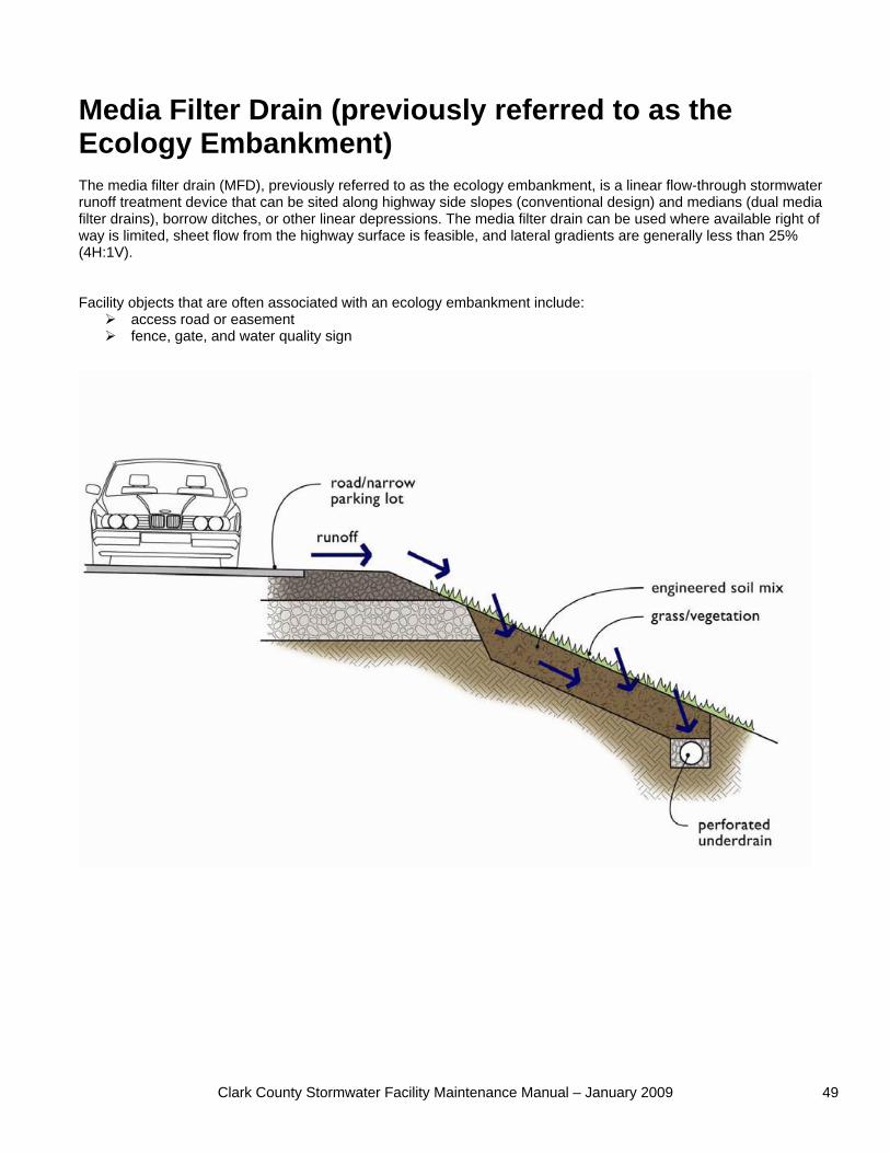
Clark County Stormwater Facility Maintenance Manual – January 2009 49
Media Filter Drain (previously referred to as the Ecology Embankment) The media filter drain (MFD), previously referred to as the ecology embankment, is a linear flow-through stormwater runoff treatment device that can be sited along highway side slopes (conventional design) and medians (dual media filter drains), borrow ditches, or other linear depressions. The media filter drain can be used where available right of way is limited, sheet flow from the highway surface is feasible, and lateral gradients are generally less than 25% (4H:1V). Facility objects that are often associated with an ecology embankment include:
access road or easement fence, gate, and water quality sign
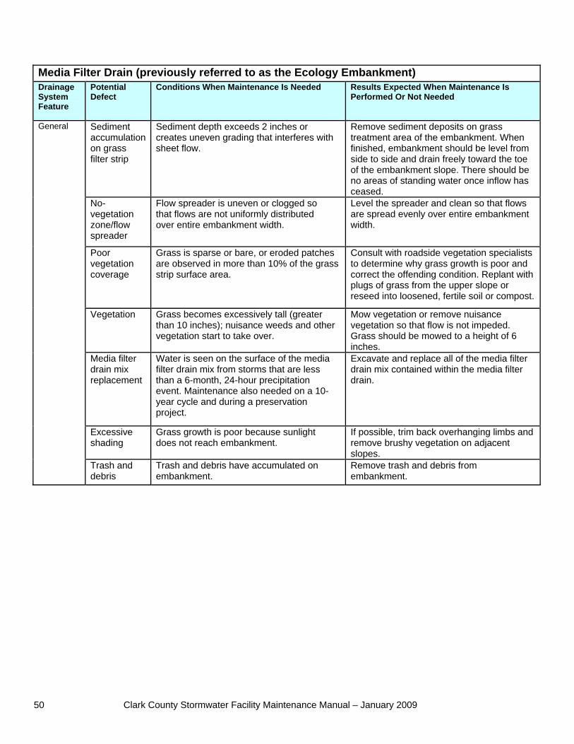
Clark County Stormwater Facility Maintenance Manual – January 2009 50
Media Filter Drain (previously referred to as the Ecology Embankment) Drainage System Feature
Potential Defect
Conditions When Maintenance Is Needed Results Expected When Maintenance Is Performed Or Not Needed
Sediment accumulation on grass filter strip
Sediment depth exceeds 2 inches or creates uneven grading that interferes with sheet flow.
Remove sediment deposits on grass treatment area of the embankment. When finished, embankment should be level from side to side and drain freely toward the toe of the embankment slope. There should be no areas of standing water once inflow has ceased.
No-vegetation zone/flow spreader
Flow spreader is uneven or clogged so that flows are not uniformly distributed over entire embankment width.
Level the spreader and clean so that flows are spread evenly over entire embankment width.
Poor vegetation coverage
Grass is sparse or bare, or eroded patches are observed in more than 10% of the grass strip surface area.
Consult with roadside vegetation specialists to determine why grass growth is poor and correct the offending condition. Replant withplugs of grass from the upper slope or reseed into loosened, fertile soil or compost.
Vegetation Grass becomes excessively tall (greater than 10 inches); nuisance weeds and other vegetation start to take over.
Mow vegetation or remove nuisance vegetation so that flow is not impeded. Grass should be mowed to a height of 6 inches.
Media filter drain mix replacement
Water is seen on the surface of the media filter drain mix from storms that are less than a 6-month, 24-hour precipitation event. Maintenance also needed on a 10- year cycle and during a preservation project.
Excavate and replace all of the media filter drain mix contained within the media filter drain.
Excessive shading
Grass growth is poor because sunlight does not reach embankment.
If possible, trim back overhanging limbs andremove brushy vegetation on adjacent slopes.
General
Trash and debris
Trash and debris have accumulated on embankment.
Remove trash and debris from embankment.
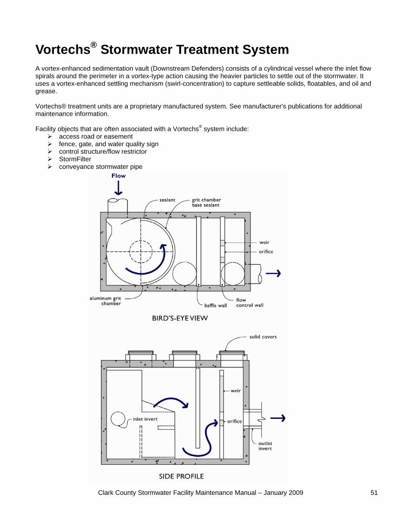
Clark County Stormwater Facility Maintenance Manual – January 2009 51
Vortechs® Stormwater Treatment System A vortex-enhanced sedimentation vault (Downstream Defenders) consists of a cylindrical vessel where the inlet flow spirals around the perimeter in a vortex-type action causing the heavier particles to settle out of the stormwater. It uses a vortex-enhanced settling mechanism (swirl-concentration) to capture settleable solids, floatables, and oil and grease. Vortechs® treatment units are a proprietary manufactured system. See manufacturer's publications for additional maintenance information. Facility objects that are often associated with a Vortechs® system include:
access road or easement fence, gate, and water quality sign control structure/flow restrictor StormFilter conveyance stormwater pipe
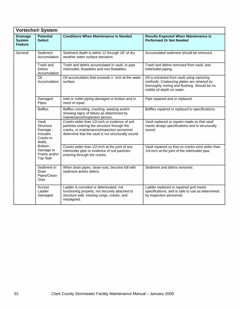
Clark County Stormwater Facility Maintenance Manual – January 2009 52
Vortechs® System Drainage System Feature
Potential Defect
Conditions When Maintenance Is Needed Results Expected When Maintenance Is Performed Or Not Needed
Sediment Accumulation
Sediment depth is within 12 through 18” of dry weather water surface elevation.
Accumulated sediment should be removed.
Trash and Debris Accumulation
Trash and debris accumulated in vault, or pipe inlet/outlet, floatables and non-floatables.
Trash and debris removed from vault, and inlet/outlet piping.
Oil Accumulation
Oil accumulation that exceeds 1- inch at the water surface.
Oil is extracted from vault using vactoring methods. Coalescing plates are cleaned by thoroughly rinsing and flushing. Should be no visible oil depth on water.
Damaged Pipes
Inlet or outlet piping damaged or broken and in need of repair.
Pipe repaired and or replaced.
Baffles Baffles corroding, cracking, warping and/or showing signs of failure as determined by maintenance/inspection person.
Baffles repaired or replaced to specifications.
Cracks wider than 1/2-inch or evidence of soil particles entering the structure through the cracks, or maintenance/inspection personnel determine that the vault is not structurally sound.
Vault replaced or repairs made so that vault meets design specifications and is structurally sound.
Vault Structure Damage - Includes Cracks in Walls, Bottom, Damage to Frame and/or Top Slab
Cracks wider than 1/2-inch at the joint of any inlet/outlet pipe or evidence of soil particles entering through the cracks.
Vault repaired so that no cracks exist wider than 1/4-inch at the joint of the inlet/outlet pipe.
Sediment in Drain Pipes/Clean-Outs
When drain pipes, clean-outs, become full with sediment and/or debris.
Sediment and debris removed.
General
Access Ladder Damaged
Ladder is corroded or deteriorated, not functioning properly, not securely attached to structure wall, missing rungs, cracks, and misaligned.
Ladder replaced or repaired and meets specifications, and is safe to use as determined by inspection personnel.
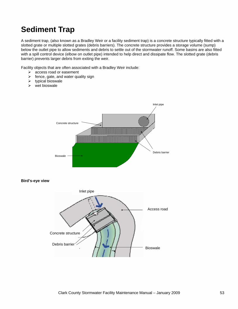
Clark County Stormwater Facility Maintenance Manual – January 2009 53
Inlet pipe
Debris barrier
Concrete structure
Bioswale
Access road
Bioswale
Inlet pipe
Debris barrier
Concrete structure
Sediment Trap A sediment trap, (also known as a Bradley Weir or a facility sediment trap) is a concrete structure typically fitted with a slotted grate or multiple slotted grates (debris barriers). The concrete structure provides a storage volume (sump) below the outlet pipe to allow sediments and debris to settle out of the stormwater runoff. Some basins are also fitted with a spill control device (elbow on outlet pipe) intended to help direct and dissipate flow. The slotted grate (debris barrier) prevents larger debris from exiting the weir. Facility objects that are often associated with a Bradley Weir include:
access road or easement fence, gate, and water quality sign typical bioswale wet bioswale
Bird’s-eye view
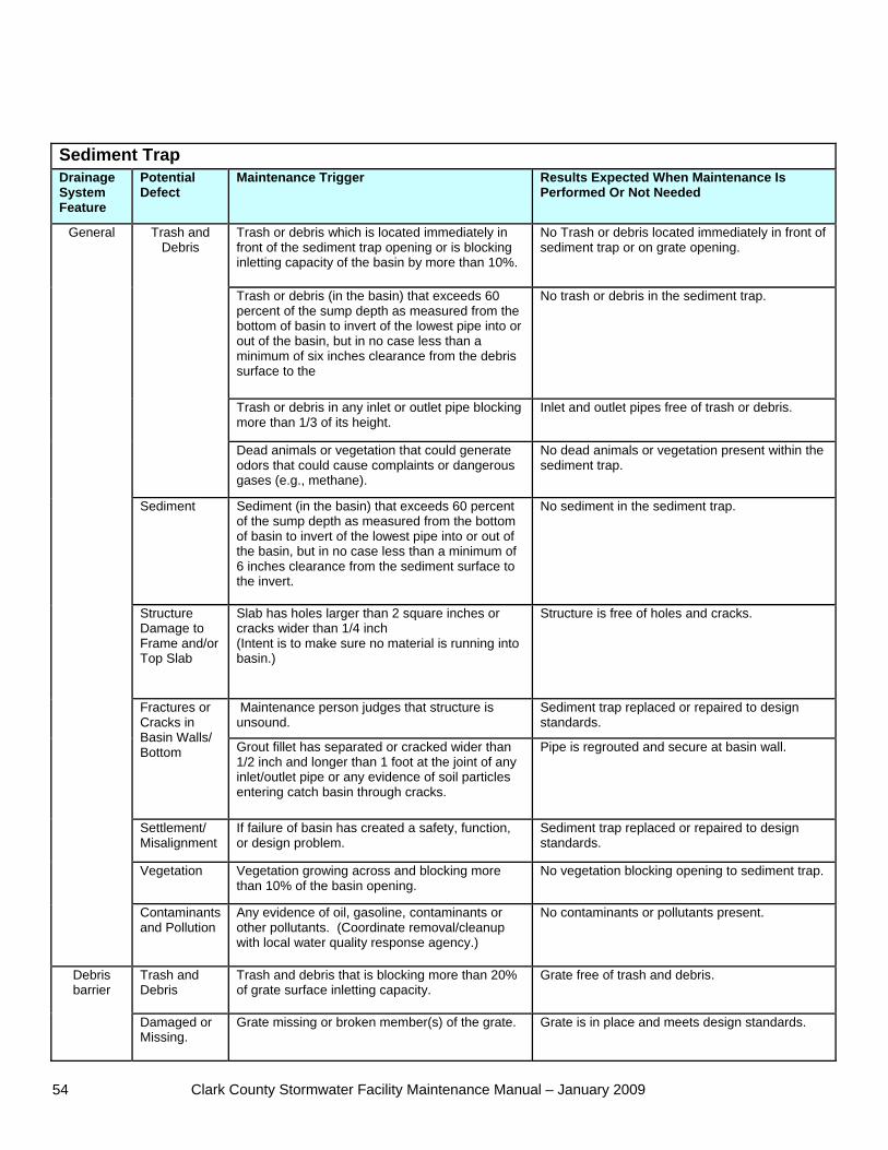
Clark County Stormwater Facility Maintenance Manual – January 2009 54
Sediment Trap Drainage System Feature
Potential Defect
Maintenance Trigger Results Expected When Maintenance Is Performed Or Not Needed
Trash or debris which is located immediately in front of the sediment trap opening or is blocking inletting capacity of the basin by more than 10%.
No Trash or debris located immediately in front of sediment trap or on grate opening.
Trash or debris (in the basin) that exceeds 60 percent of the sump depth as measured from the bottom of basin to invert of the lowest pipe into or out of the basin, but in no case less than a minimum of six inches clearance from the debris surface to the
No trash or debris in the sediment trap.
Trash or debris in any inlet or outlet pipe blocking more than 1/3 of its height.
Inlet and outlet pipes free of trash or debris.
Trash and Debris
Dead animals or vegetation that could generate odors that could cause complaints or dangerous gases (e.g., methane).
No dead animals or vegetation present within the sediment trap.
Sediment Sediment (in the basin) that exceeds 60 percent of the sump depth as measured from the bottom of basin to invert of the lowest pipe into or out of the basin, but in no case less than a minimum of 6 inches clearance from the sediment surface to the invert.
No sediment in the sediment trap.
Structure Damage to Frame and/or Top Slab
Slab has holes larger than 2 square inches or cracks wider than 1/4 inch (Intent is to make sure no material is running into basin.)
Structure is free of holes and cracks.
Maintenance person judges that structure is unsound.
Sediment trap replaced or repaired to design standards.
Fractures or Cracks in Basin Walls/ Bottom Grout fillet has separated or cracked wider than
1/2 inch and longer than 1 foot at the joint of any inlet/outlet pipe or any evidence of soil particles entering catch basin through cracks.
Pipe is regrouted and secure at basin wall.
Settlement/ Misalignment
If failure of basin has created a safety, function, or design problem.
Sediment trap replaced or repaired to design standards.
Vegetation Vegetation growing across and blocking more than 10% of the basin opening.
No vegetation blocking opening to sediment trap.
General
Contaminants and Pollution
Any evidence of oil, gasoline, contaminants or other pollutants. (Coordinate removal/cleanup with local water quality response agency.)
No contaminants or pollutants present.
Trash and Debris
Trash and debris that is blocking more than 20% of grate surface inletting capacity.
Grate free of trash and debris. Debris barrier
Damaged or Missing.
Grate missing or broken member(s) of the grate. Grate is in place and meets design standards.
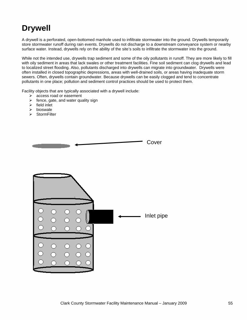
Clark County Stormwater Facility Maintenance Manual – January 2009 55
Drywell A drywell is a perforated, open-bottomed manhole used to infiltrate stormwater into the ground. Drywells temporarily store stormwater runoff during rain events. Drywells do not discharge to a downstream conveyance system or nearby surface water. Instead, drywells rely on the ability of the site’s soils to infiltrate the stormwater into the ground. While not the intended use, drywells trap sediment and some of the oily pollutants in runoff. They are more likely to fill with oily sediment in areas that lack swales or other treatment facilities. Fine soil sediment can clog drywells and lead to localized street flooding. Also, pollutants discharged into drywells can migrate into groundwater. Drywells were often installed in closed topographic depressions, areas with well-drained soils, or areas having inadequate storm sewers. Often, drywells contain groundwater. Because drywells can be easily clogged and tend to concentrate pollutants in one place; pollution and sediment control practices should be used to protect them.
Facility objects that are typically associated with a drywell include: access road or easement fence, gate, and water quality sign field inlet bioswale StormFilter
Inlet pipe
Cover
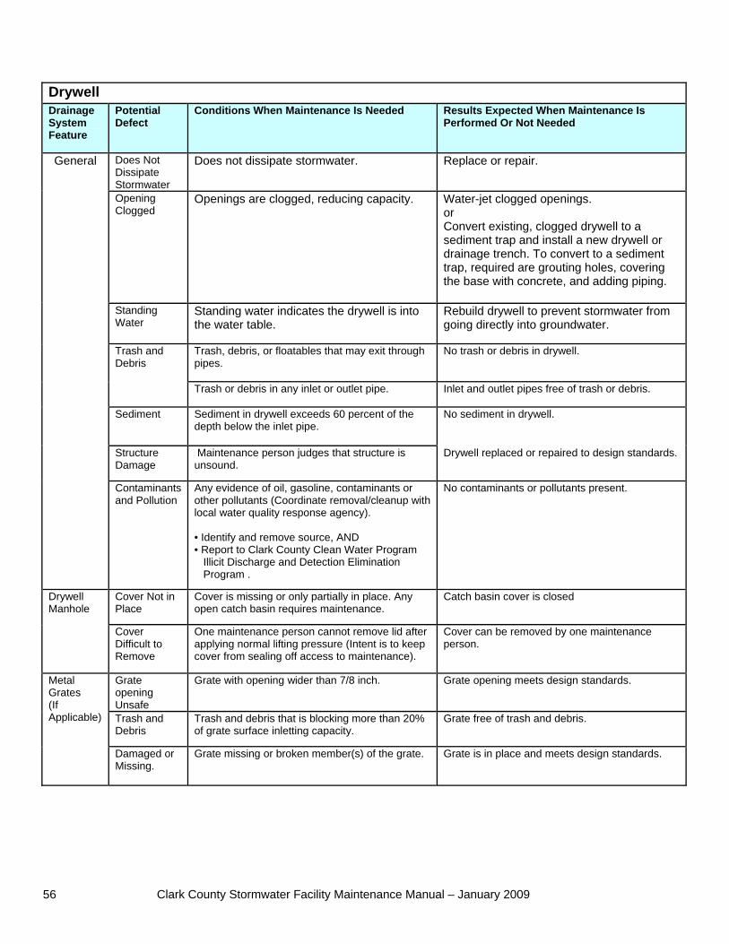
Clark County Stormwater Facility Maintenance Manual – January 2009 56
Drywell Drainage System Feature
Potential Defect
Conditions When Maintenance Is Needed Results Expected When Maintenance Is Performed Or Not Needed
Does Not Dissipate Stormwater
Does not dissipate stormwater. Replace or repair.
Opening Clogged
Openings are clogged, reducing capacity. Water-jet clogged openings. or Convert existing, clogged drywell to a sediment trap and install a new drywell or drainage trench. To convert to a sediment trap, required are grouting holes, covering the base with concrete, and adding piping.
Standing Water
Standing water indicates the drywell is into the water table.
Rebuild drywell to prevent stormwater from going directly into groundwater.
Trash, debris, or floatables that may exit through pipes.
No trash or debris in drywell. Trash and Debris
Trash or debris in any inlet or outlet pipe. Inlet and outlet pipes free of trash or debris.
Sediment Sediment in drywell exceeds 60 percent of the depth below the inlet pipe.
No sediment in drywell.
Structure Damage
Maintenance person judges that structure is unsound.
Drywell replaced or repaired to design standards.
General
Contaminants and Pollution
Any evidence of oil, gasoline, contaminants or other pollutants (Coordinate removal/cleanup with local water quality response agency). • Identify and remove source, AND • Report to Clark County Clean Water Program Illicit Discharge and Detection Elimination Program .
No contaminants or pollutants present.
Cover Not in Place
Cover is missing or only partially in place. Any open catch basin requires maintenance.
Catch basin cover is closed Drywell Manhole
Cover Difficult to Remove
One maintenance person cannot remove lid after applying normal lifting pressure (Intent is to keep cover from sealing off access to maintenance).
Cover can be removed by one maintenance person.
Grate opening Unsafe
Grate with opening wider than 7/8 inch. Grate opening meets design standards.
Trash and Debris
Trash and debris that is blocking more than 20% of grate surface inletting capacity.
Grate free of trash and debris.
Metal Grates (If Applicable)
Damaged or Missing.
Grate missing or broken member(s) of the grate. Grate is in place and meets design standards.
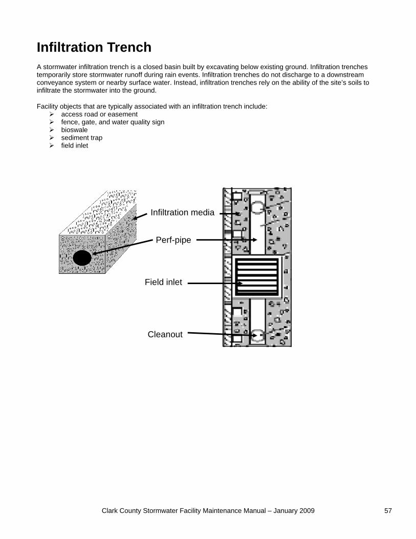
Clark County Stormwater Facility Maintenance Manual – January 2009 57
Infiltration Trench A stormwater infiltration trench is a closed basin built by excavating below existing ground. Infiltration trenches temporarily store stormwater runoff during rain events. Infiltration trenches do not discharge to a downstream conveyance system or nearby surface water. Instead, infiltration trenches rely on the ability of the site’s soils to infiltrate the stormwater into the ground.
Facility objects that are typically associated with an infiltration trench include: access road or easement fence, gate, and water quality sign bioswale sediment trap field inlet
Perf-pipe
Infiltration media
Field inlet
Cleanout
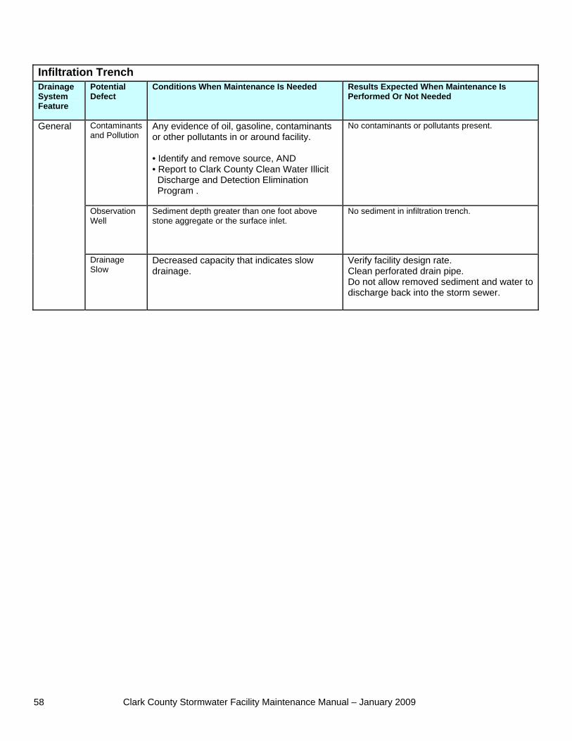
Clark County Stormwater Facility Maintenance Manual – January 2009 58
Infiltration Trench Drainage System Feature
Potential Defect
Conditions When Maintenance Is Needed Results Expected When Maintenance Is Performed Or Not Needed
Contaminants and Pollution
Any evidence of oil, gasoline, contaminants or other pollutants in or around facility. • Identify and remove source, AND • Report to Clark County Clean Water Illicit Discharge and Detection Elimination Program .
No contaminants or pollutants present.
Observation Well
Sediment depth greater than one foot above stone aggregate or the surface inlet.
No sediment in infiltration trench.
General
Drainage Slow
Decreased capacity that indicates slow drainage.
Verify facility design rate. Clean perforated drain pipe. Do not allow removed sediment and water to discharge back into the storm sewer.
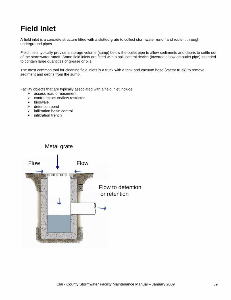
Clark County Stormwater Facility Maintenance Manual – January 2009 59
Field Inlet A field inlet is a concrete structure fitted with a slotted grate to collect stormwater runoff and route it through underground pipes. Field inlets typically provide a storage volume (sump) below the outlet pipe to allow sediments and debris to settle out of the stormwater runoff. Some field inlets are fitted with a spill control device (inverted elbow on outlet pipe) intended to contain large quantities of grease or oils. The most common tool for cleaning field inlets is a truck with a tank and vacuum hose (vactor truck) to remove sediment and debris from the sump. Facility objects that are typically associated with a field inlet include:
access road or easement control structure/flow restrictor bioswale detention pond infiltration basin control infiltration trench
FlowFlow
Flow to detentionor retention
Metal grate
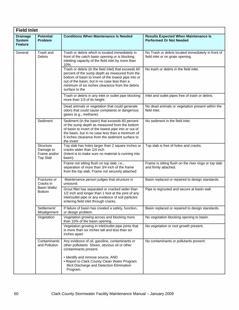
Clark County Stormwater Facility Maintenance Manual – January 2009 60
Field Inlet Drainage System Feature
Potential Problem
Conditions When Maintenance Is Needed Results Expected When Maintenance Is Performed Or Not Needed
Trash or debris which is located immediately in front of the catch basin opening or is blocking inletting capacity of the field inlet by more than 10%.
No Trash or debris located immediately in front of field inlet or on grate opening.
Trash or debris (in the field inlet) that exceeds 60 percent of the sump depth as measured from the bottom of basin to invert of the lowest pipe into or out of the basin, but in no case less than a minimum of six inches clearance from the debris surface to the
No trash or debris in the field inlet.
Trash or debris in any inlet or outlet pipe blocking more than 1/3 of its height.
Inlet and outlet pipes free of trash or debris.
Trash and Debris
Dead animals or vegetation that could generate odors that could cause complaints or dangerous gases (e.g., methane).
No dead animals or vegetation present within the field inlet.
Sediment Sediment (in the basin) that exceeds 60 percent of the sump depth as measured from the bottom of basin to invert of the lowest pipe into or out of the basin, but in no case less than a minimum of 6 inches clearance from the sediment surface to the invert
No sediment in the field inlet.
Top slab has holes larger than 2 square inches or cracks wider than 1/4 inch (Intent is to make sure no material is running into basin).
Top slab is free of holes and cracks. Structure Damage to Frame and/or Top Slab
Frame not sitting flush on top slab, i.e., separation of more than 3/4 inch of the frame from the top slab. Frame not securely attached
Frame is sitting flush on the riser rings or top slab and firmly attached.
Maintenance person judges that structure is unsound.
Basin replaced or repaired to design standards. Fractures or Cracks in Basin Walls/ Bottom
Grout fillet has separated or cracked wider than 1/2 inch and longer than 1 foot at the joint of any inlet/outlet pipe or any evidence of soil particles entering field inlet through cracks.
Pipe is regrouted and secure at basin wall.
Settlement/ Misalignment
If failure of basin has created a safety, function, or design problem.
Basin replaced or repaired to design standards.
Vegetation growing across and blocking more than 10% of the basin opening.
No vegetation blocking opening to basin. Vegetation
Vegetation growing in inlet/outlet pipe joints that is more than six inches tall and less than six inches apart.
No vegetation or root growth present.
General
Contaminants and Pollution
Any evidence of oil, gasoline, contaminants or other pollutants Sheen, obvious oil or other contaminants present. • Identify and remove source, AND • Report to Clark County Clean Water Program Illicit Discharge and Detection Elimination Program.
No contaminants or pollutants present.
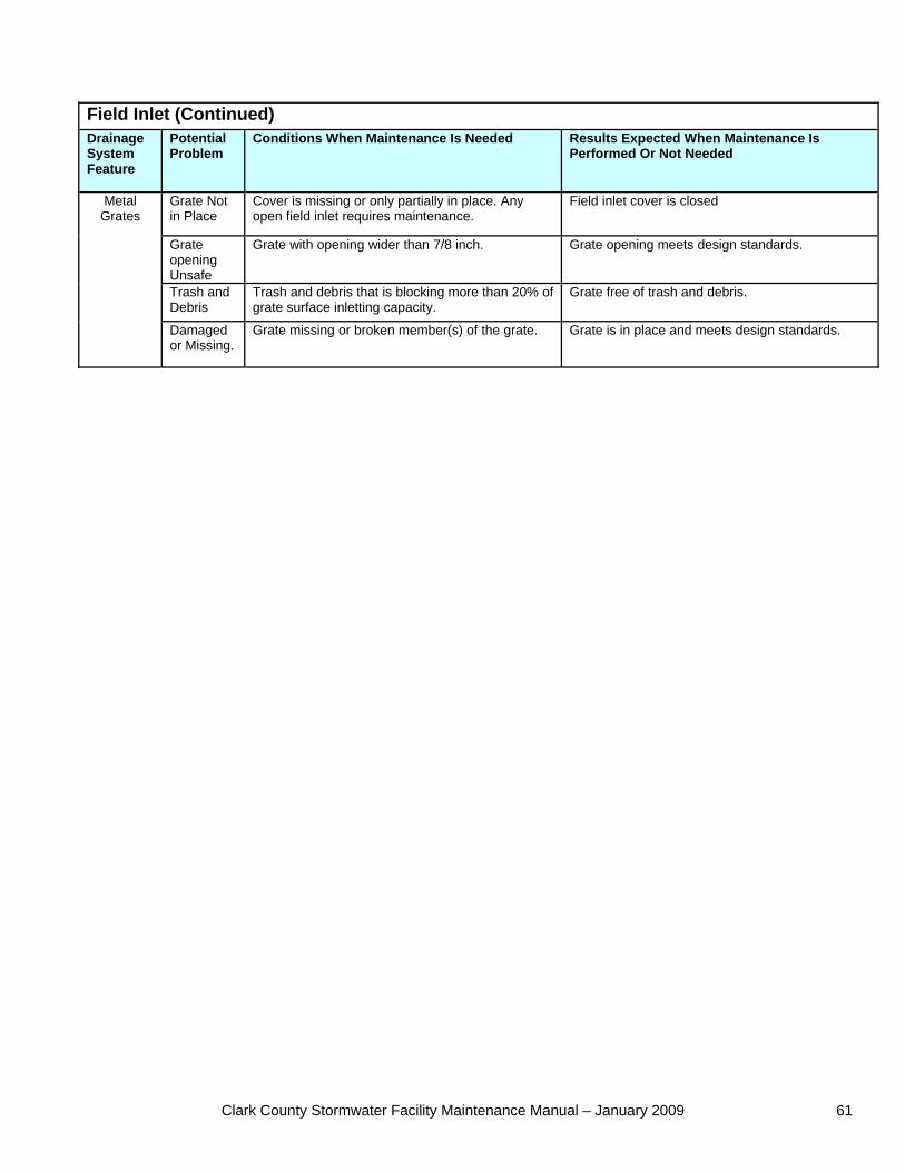
Clark County Stormwater Facility Maintenance Manual – January 2009 61
Field Inlet (Continued) Drainage System Feature
Potential Problem
Conditions When Maintenance Is Needed Results Expected When Maintenance Is Performed Or Not Needed
Grate Not in Place
Cover is missing or only partially in place. Any open field inlet requires maintenance.
Field inlet cover is closed
Grate opening Unsafe
Grate with opening wider than 7/8 inch. Grate opening meets design standards.
Trash and Debris
Trash and debris that is blocking more than 20% of grate surface inletting capacity.
Grate free of trash and debris.
Metal Grates
Damaged or Missing.
Grate missing or broken member(s) of the grate. Grate is in place and meets design standards.
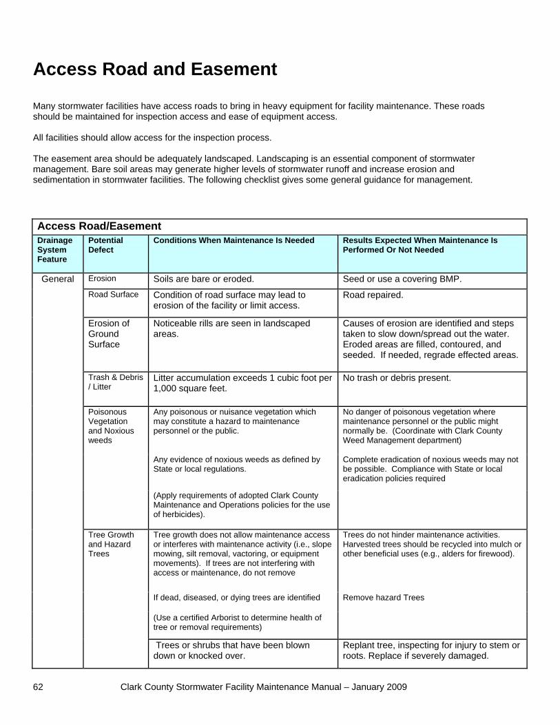
Clark County Stormwater Facility Maintenance Manual – January 2009 62
Access Road and Easement Many stormwater facilities have access roads to bring in heavy equipment for facility maintenance. These roads should be maintained for inspection access and ease of equipment access. All facilities should allow access for the inspection process. The easement area should be adequately landscaped. Landscaping is an essential component of stormwater management. Bare soil areas may generate higher levels of stormwater runoff and increase erosion and sedimentation in stormwater facilities. The following checklist gives some general guidance for management. Access Road/Easement Drainage System Feature
Potential Defect
Conditions When Maintenance Is Needed Results Expected When Maintenance Is Performed Or Not Needed
Erosion Soils are bare or eroded. Seed or use a covering BMP. Road Surface Condition of road surface may lead to
erosion of the facility or limit access. Road repaired.
Erosion of Ground Surface
Noticeable rills are seen in landscaped areas.
Causes of erosion are identified and steps taken to slow down/spread out the water. Eroded areas are filled, contoured, and seeded. If needed, regrade effected areas.
Trash & Debris / Litter
Litter accumulation exceeds 1 cubic foot per 1,000 square feet.
No trash or debris present.
Any poisonous or nuisance vegetation which may constitute a hazard to maintenance personnel or the public.
No danger of poisonous vegetation where maintenance personnel or the public might normally be. (Coordinate with Clark County Weed Management department)
Any evidence of noxious weeds as defined by State or local regulations.
Complete eradication of noxious weeds may not be possible. Compliance with State or local eradication policies required
Poisonous Vegetation and Noxious weeds
(Apply requirements of adopted Clark County Maintenance and Operations policies for the use of herbicides).
Tree growth does not allow maintenance access or interferes with maintenance activity (i.e., slope mowing, silt removal, vactoring, or equipment movements). If trees are not interfering with access or maintenance, do not remove
Trees do not hinder maintenance activities. Harvested trees should be recycled into mulch or other beneficial uses (e.g., alders for firewood).
If dead, diseased, or dying trees are identified Remove hazard Trees
(Use a certified Arborist to determine health of tree or removal requirements)
General
Tree Growth and Hazard Trees
Trees or shrubs that have been blown down or knocked over.
Replant tree, inspecting for injury to stem or roots. Replace if severely damaged.
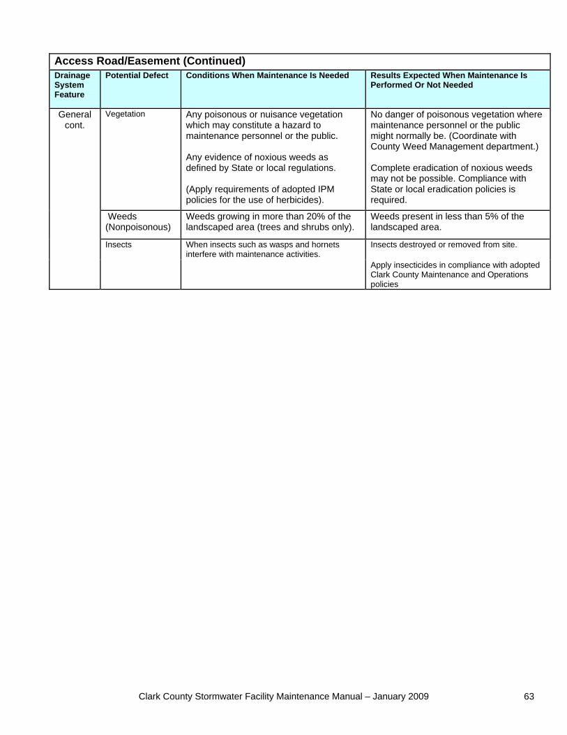
Clark County Stormwater Facility Maintenance Manual – January 2009 63
Access Road/Easement (Continued) Drainage System Feature
Potential Defect Conditions When Maintenance Is Needed Results Expected When Maintenance Is Performed Or Not Needed
Vegetation Any poisonous or nuisance vegetation which may constitute a hazard to maintenance personnel or the public. Any evidence of noxious weeds as defined by State or local regulations. (Apply requirements of adopted IPM policies for the use of herbicides).
No danger of poisonous vegetation where maintenance personnel or the public might normally be. (Coordinate with County Weed Management department.) Complete eradication of noxious weeds may not be possible. Compliance with State or local eradication policies is required.
Weeds (Nonpoisonous)
Weeds growing in more than 20% of the landscaped area (trees and shrubs only).
Weeds present in less than 5% of the landscaped area.
Insects destroyed or removed from site.
General cont.
Insects When insects such as wasps and hornets interfere with maintenance activities.
Apply insecticides in compliance with adopted Clark County Maintenance and Operations policies
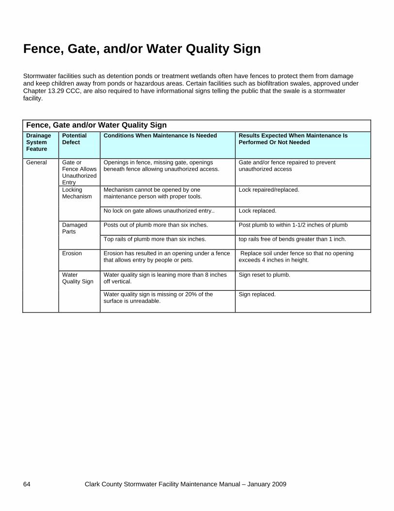
Clark County Stormwater Facility Maintenance Manual – January 2009 64
Fence, Gate, and/or Water Quality Sign Stormwater facilities such as detention ponds or treatment wetlands often have fences to protect them from damage and keep children away from ponds or hazardous areas. Certain facilities such as biofiltration swales, approved under Chapter 13.29 CCC, are also required to have informational signs telling the public that the swale is a stormwater facility. Fence, Gate and/or Water Quality Sign Drainage System Feature
Potential Defect
Conditions When Maintenance Is Needed Results Expected When Maintenance Is Performed Or Not Needed
Gate or Fence Allows Unauthorized Entry
Openings in fence, missing gate, openings beneath fence allowing unauthorized access.
Gate and/or fence repaired to prevent unauthorized access
Mechanism cannot be opened by one maintenance person with proper tools.
Lock repaired/replaced. Locking Mechanism
No lock on gate allows unauthorized entry.. Lock replaced.
Posts out of plumb more than six inches. Post plumb to within 1-1/2 inches of plumb Damaged Parts
Top rails of plumb more than six inches. top rails free of bends greater than 1 inch.
Erosion Erosion has resulted in an opening under a fence that allows entry by people or pets.
Replace soil under fence so that no opening exceeds 4 inches in height.
Water quality sign is leaning more than 8 inches off vertical.
Sign reset to plumb.
General
Water Quality Sign
Water quality sign is missing or 20% of the surface is unreadable.
Sign replaced.
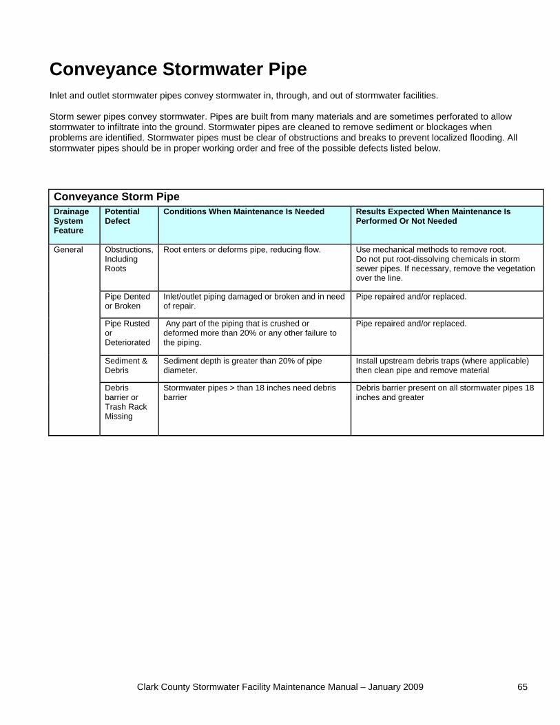
Clark County Stormwater Facility Maintenance Manual – January 2009 65
Conveyance Stormwater Pipe Inlet and outlet stormwater pipes convey stormwater in, through, and out of stormwater facilities. Storm sewer pipes convey stormwater. Pipes are built from many materials and are sometimes perforated to allow stormwater to infiltrate into the ground. Stormwater pipes are cleaned to remove sediment or blockages when problems are identified. Stormwater pipes must be clear of obstructions and breaks to prevent localized flooding. All stormwater pipes should be in proper working order and free of the possible defects listed below. Conveyance Storm Pipe Drainage System Feature
Potential Defect
Conditions When Maintenance Is Needed Results Expected When Maintenance Is Performed Or Not Needed
Obstructions, Including Roots
Root enters or deforms pipe, reducing flow. Use mechanical methods to remove root. Do not put root-dissolving chemicals in storm sewer pipes. If necessary, remove the vegetation over the line.
Pipe Dented or Broken
Inlet/outlet piping damaged or broken and in need of repair.
Pipe repaired and/or replaced.
Pipe Rusted or Deteriorated
Any part of the piping that is crushed or deformed more than 20% or any other failure to the piping.
Pipe repaired and/or replaced.
Sediment & Debris
Sediment depth is greater than 20% of pipe diameter.
Install upstream debris traps (where applicable) then clean pipe and remove material
General
Debris barrier or Trash Rack Missing
Stormwater pipes > than 18 inches need debris barrier
Debris barrier present on all stormwater pipes 18 inches and greater
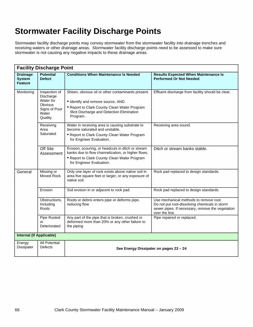
Clark County Stormwater Facility Maintenance Manual – January 2009 66
Stormwater Facility Discharge Points Stormwater facility discharge points may convey stormwater from the stormwater facility into drainage trenches and receiving waters or other drainage areas. Stormwater facility discharge points need to be assessed to make sure stormwater is not causing any negative impacts to these drainage areas. Facility Discharge Point Drainage System Feature
Potential Defect
Conditions When Maintenance Is Needed Results Expected When Maintenance Is Performed Or Not Needed
Inspection of Discharge Water for Obvious Signs of Poor Water Quality.
Sheen, obvious oil or other contaminants present. • Identify and remove source, AND • Report to Clark County Clean Water Program Illicit Discharge and Detection Elimination Program .
Effluent discharge from facility should be clear.
Receiving Area Saturated
Water in receiving area is causing substrate to become saturated and unstable. • Report to Clark County Clean Water Program for Engineer Evaluation.
Receiving area sound.
Monitoring
Off Site Assessment
Erosion, scouring, or headcuts in ditch or stream banks due to flow channelization, or higher flows. • Report to Clark County Clean Water Program for Engineer Evaluation.
Ditch or stream banks stable.
Missing or Moved Rock
Only one layer of rock exists above native soil in area five square feet or larger, or any exposure of native soil.
Rock pad replaced to design standards.
Erosion Soil erosion in or adjacent to rock pad. Rock pad replaced to design standards.
Obstructions, Including Roots
Roots or debris enters pipe or deforms pipe, reducing flow
Use mechanical methods to remove root. Do not put root-dissolving chemicals in storm sewer pipes. If necessary, remove the vegetation over the line.
General
Pipe Rusted or Deteriorated
Any part of the pipe that is broken, crushed or deformed more than 20% or any other failure to the piping
Pipe repaired or replaced.
Internal (If Applicable)
Energy Dissipater
All Potential Defects See Energy Dissipater on pages 23 – 24
Clark County Stormwater Facility Maintenance Manual – January 2009 67
Vegetation Management The following practices are adapted, with minor modifications for format and local practices, from City of Portland Parks Pest Management Policy (April 1999).
General Goals and Philosophy Clark County recognizes the special importance of rivers, streams, wetlands, ponds, and stormwater control and treatment facilities. The sensitive nature of such habitats, their plant and animal communities, and their direct link with other waterways require that we establish specific policies to ensure their health. All landscape management decisions for controlling unwanted vegetation, diseases, and pests should follow Integrated Pest Management principles and decision-making rationale. These are:
Proper planning and management decisions begin the IPM process Cultural methods of vegetation and pest control are preferred and are first employed Mechanical means of vegetation and pest control are next in line of preference, and are utilized where
feasible Biological methods of vegetation and pest control are considered before chemical means, where they are
feasible Botanical and synthetic pesticides are used only when no other feasible methods exist
General Practices Use Only Appropriate Plants Clark County has adopted a list of approved plants for use in development projects. The list also has prohibited undesirable plants. Only plants approved for use in the Clark County Plant List are allowed for use in plantings in unincorporated areas.
Vegetation and Pest Management in Stormwater Control Facilities Stormwater control facilities include biofiltration treatment swales, treatment wetlands, treatment ponds, detention ponds, open channels, and infiltration basins. Stormwater control facilities discharge to surface water or groundwater either directly or through pipes or ditches. Many facilities are built to remove pollutants from stormwater. Generally, vegetation should be maintained to blend into surrounding areas. Stormwater facilities can provide habitat for aquatic life and birds. Promoting natural vegetation where feasible improves habitat. Swales often blend into intensively managed landscapes. Pond perimeters can include natural vegetation. The use of pesticides and, in most cases fertilizer, is not compatible with the task of pollutant removal or the direct connection of stormwater facilities to streams and groundwater. Features of Stormwater Facilities:
There is a mix of native and non-native plants Generally not used by the public Include areas managed to promote design function, such as turf in swales Managed landscapes may be nearby May be used by fish and wildlife
Objectives for Stormwater Facilities:
Maintain healthy plant communities Avoid or minimize need for chemical intervention Control invasive plants where feasible
Clark County Stormwater Facility Maintenance Manual – January 2009 68
No bare soil areas are allowed Tolerance for natural appearance and weeds
Practices The vegetation management focus is establishing and maintaining healthy low-maintenance native plantings and sustaining the design function of vegetated filters such as biofiltration swales. This includes controlling invasive plants where feasible, and planting cover on bare soils. Only use plants on the City of Vancouver plant list or the Clark County Plant List (Ordinance 1995-01-26). In some cases, the original plantings may not be appropriate for the actual condition at a facility. One example is a frequently flooded swale that cannot support normal turf. In cases like this, replace turf with appropriate wetland plants if the underlying drainage problem cannot be fixed. Consider the use of soil amendments such as compost before using fertilizer. Limit mulch use to covering bare soil while establishing plantings. Chemical use should be avoided within 25 feet of any area that holds or conveys surface water or stormwater. This includes the base of a biofiltration swale. Trees or shrubs that block access roads may be trimmed (or removed if within the access road) when access is required for maintenance by heavy equipment. Trees that pose a risk to stormwater structures due to root growth may be removed and replaced by smaller shrubs.