Embed Size (px)
Citation preview
Stormwater & Sewerage Services Review
Proposed Cinema Development
148 Rouse Street Tenterfield, 2372
Client: Mills Gorman Architects on behalf of
Mr Chris Hsu
Version 1 Malcolm Whitton Date: 17 Sept 2021 Managing Director Whitton Engineering
Stormwater Design Report WEDS Civil Engineering - Structural Engineering – Environmental Assessments – Project Management – Drafting Services
2
Stormwater Design Report WEDS Civil Engineering - Structural Engineering – Environmental Assessments – Project Management – Drafting Services
3
1. Overview
Whitton Engineering has been commissioned by Mills Gorman Architects, to carry out a Stormwater & Sewerage Services Review for the proposed cinema complex development at 148 Rouse St, Tenterfield. Part 1 of the review is to evaluate the performance of the existing stormwater services in a 1% (1 in 100) AEP event and to assess the capability of the proposed modifications to the stormwater system under the same conditions. Part 2 of the report will evaluate the proposed development and supply a draft stormwater drainage layout for the roof and carpark for the purpose of the Development Application. Part 3 will review the existing sewer services and supply a draft proposed layout for the purpose of the Development Application. Throughout the report the following abbreviations will be used. Tenterfield Shire Council TSC Mills Gorman Architects MGA Whitton Engineering WEDS
Stormwater Design Report WEDS Civil Engineering - Structural Engineering – Environmental Assessments – Project Management – Drafting Services
4
2. Part 1 Existing Stormwater System and Proposed Changes under 1%AEP conditions
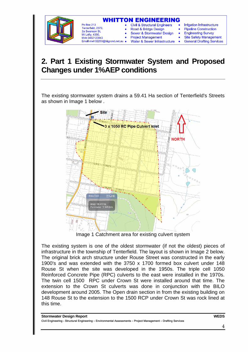
The existing stormwater system drains a 59.41 Ha section of Tenterfield's Streets as shown in Image 1 below .
Image 1 Catchment area for existing culvert system
The existing system is one of the oldest stormwater (if not the oldest) pieces of infrastructure in the township of Tenterfield. The layout is shown in Image 2 below. The original brick arch structure under Rouse Street was constructed in the early 1900's and was extended with the 3750 x 1700 formed box culvert under 148 Rouse St when the site was developed in the 1950s. The triple cell 1050 Reinforced Concrete Pipe (RPC) culverts to the east were installed in the 1970s. The twin cell 1500 RPC under Crown St were installed around that time. The extension to the Crown St culverts was done in conjunction with the BILO development around 2005. The Open drain section in from the existing building on 148 Rouse St to the extension to the 1500 RCP under Crown St was rock lined at this time.

Stormwater Design Report WEDS Civil Engineering - Structural Engineering – Environmental Assessments – Project Management – Drafting Services
5
The Development proposed will entail the replacement of the open drain section from the western side of the existing buildings on 148 Rouse St to the twin cell 1500 RCP with a 1200mm high x 3000mm wide Reinforced Concrete Box Culvert on a poured concrete base. The Culverts will then have a carpark constructed over them. Custom concrete interfaces with access/ inspection openings will incorporated to each end. Image 2 Site Layout.
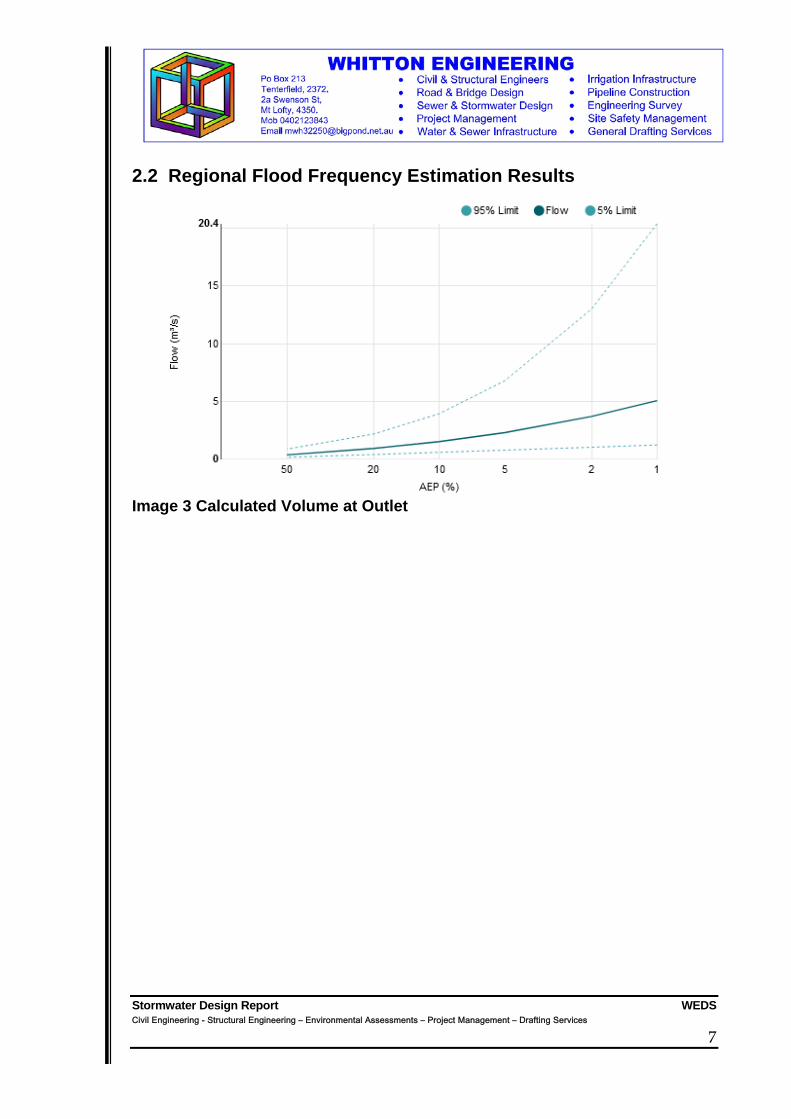
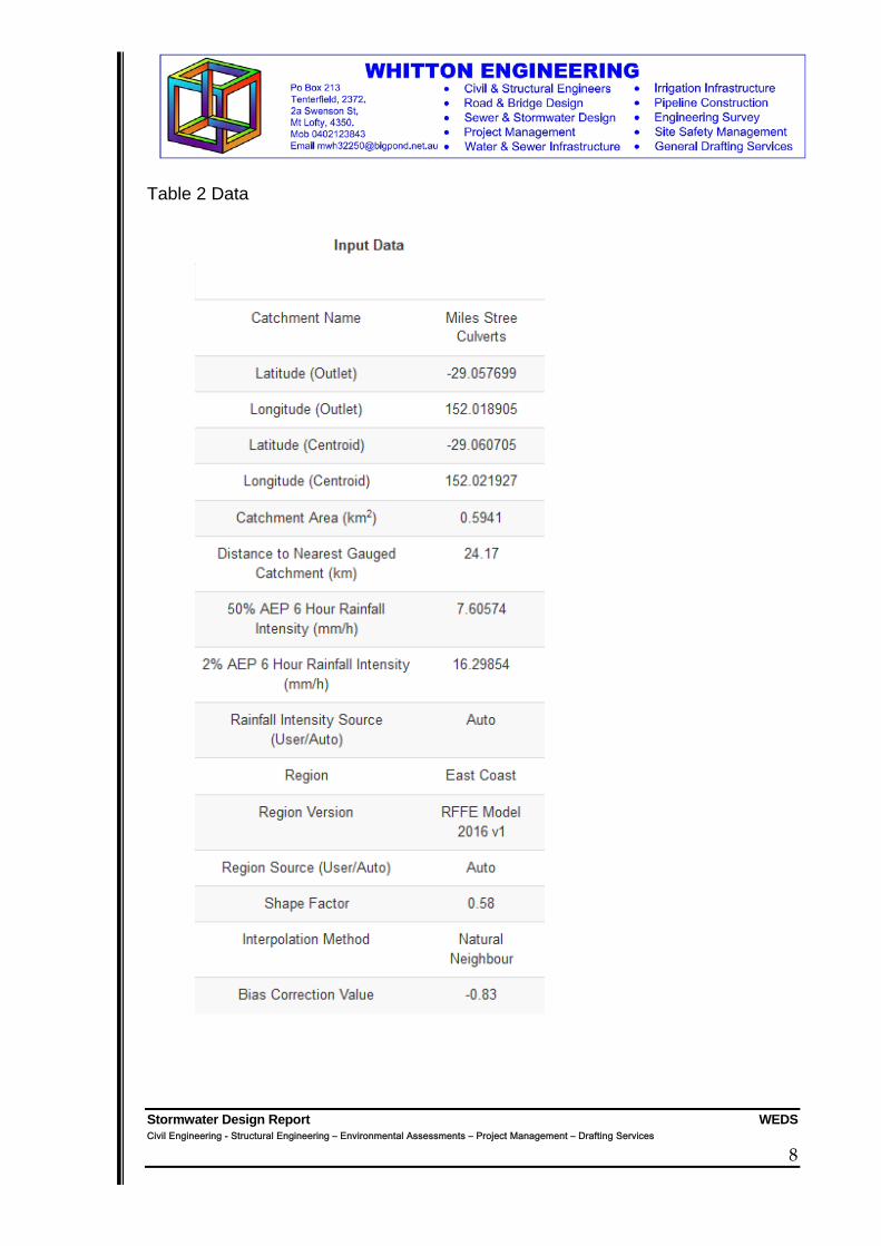
2.1 Methodology The catchment area of the culvert system was ascertained using the contour maps supplied by the NSW Spatial Services on the Six Maps viewer and shown in Image 1 above. The data was then fed into the ARR Regional Flood Frequency Estimation Model using the location of the Miles St Culvert as the discharge point and the centroid being the cul de sac at the end of Jubilee Street. The resulting catchment was modelled on a teardrop shape corresponding to the area of 59.41 Ha. The results are shown in Section 2.2 The output volume of 5.07 m3/s was then applied to the sections of the system in turn with the calculated area of discharge from each section being used for review of the next. Culvert section capacities were calculated and the results shown. The assumptions made include;

Stormwater Design Report WEDS Civil Engineering - Structural Engineering – Environmental Assessments – Project Management – Drafting Services
6
o Mannings n values used are shown in Table 1 below. 0.011 smooth concrete standard RCP, 0.016 rough concrete.
o Lengths are approximate where not picked up by Survey o No losses were assumed at transition areas where extensions were
joined to existing sections o Size of original Culvert from Authors memory of inspection carried
out in 1999. Not able to enter at this time due to confined space requirements. Very conservative estimate.
o cross sectional area from previous section outflow was used at start of new section and then adapted as flow velocity increase or decrease resulted in new cross sectional area at outflow of section.
Table 1 Assumptions and Values Used Section Length Slope Mannings n Comments 3 x 1050 RCP 35 m 1:200 0.011 Slope actually greater
than 1:200 Brick Arched Culvert
28 m 1:200 0.016 Slope unknown but not applicable due large sectional area of culvert. treat as a 4000 wide RCBC
1.7 m high x 3.45 m wide RC box culvert
62 m 1:100 0.016 Slope measured using spirit level closer to 1:80 but 1: 100 adopted
Large Open drain
36 m 1: 30 Analysis ignored as the drain cross sectional area from the detailed survey is 11 times larger than the cross section of the 1%AEP design flow rate as calculated in 2.2 below
New 1.2 m high x 3.0 m wide RC box culvert
36 m 1:30 0.011 Proposed new culvert under carpark
2 x 1500 RCP extension to existing RCP
15 m 1:100 0.011 Slope known as WEDS designed extension in 2005
2 x 1500 RCP under Crown St
18 m 1:100 0.016 Rough concrete as old pipes
Calculations, Results and design capacities are shown based on Manning's equation and the Maximum Capacity discharge, velocity and percentage of the current discharge to maximum design capacity is shown.
Stormwater Design Report WEDS Civil Engineering - Structural Engineering – Environmental Assessments – Project Management – Drafting Services
7
2.2 Regional Flood Frequency Estimation Results
Image 3 Calculated Volume at Outlet
Stormwater Design Report WEDS Civil Engineering - Structural Engineering – Environmental Assessments – Project Management – Drafting Services
8
Table 2 Data
Stormwater Design Report WEDS Civil Engineering - Structural Engineering – Environmental Assessments – Project Management – Drafting Services
9
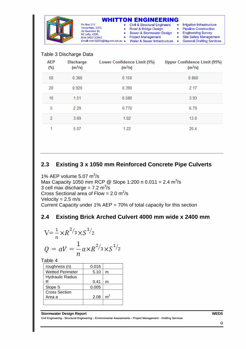
Table 3 Discharge Data
2.3 Existing 3 x 1050 mm Reinforced Concrete Pipe Culverts 1% AEP volume 5.07 m3/s Max Capacity 1050 mm RCP @ Slope 1:200 n 0.011 = 2.4 m3/s 3 cell max discharge = 7.2 m3/s Cross Sectional area of Flow = 2.0 m2/s Velocity = 2.5 m/s Current Capacity under 1% AEP = 70% of total capacity for this section 2.4 Existing Brick Arched Culvert 4000 mm wide x 2400 mm
Table 4
roughness (n) 0.016 Wetted Perimeter 5.10 m Hydraulic Radius R 0.41 m Slope S 0.005 Cross Section Area a 2.08 m2
Stormwater Design Report WEDS Civil Engineering - Structural Engineering – Environmental Assessments – Project Management – Drafting Services
10
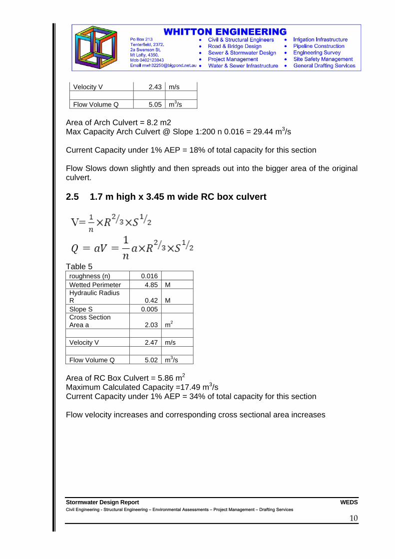
Velocity V 2.43 m/s Flow Volume Q 5.05 m3/s
Area of Arch Culvert = 8.2 m2 Max Capacity Arch Culvert @ Slope 1:200 n 0.016 = 29.44 m3/s Current Capacity under 1% AEP = 18% of total capacity for this section Flow Slows down slightly and then spreads out into the bigger area of the original culvert. 2.5 1.7 m high x 3.45 m wide RC box culvert
Table 5 roughness (n) 0.016 Wetted Perimeter 4.85 M Hydraulic Radius R 0.42 M Slope S 0.005 Cross Section Area a 2.03 m2 Velocity V 2.47 m/s Flow Volume Q 5.02 m3/s
Area of RC Box Culvert = 5.86 m2 Maximum Calculated Capacity =17.49 m3/s Current Capacity under 1% AEP = 34% of total capacity for this section Flow velocity increases and corresponding cross sectional area increases

Stormwater Design Report WEDS Civil Engineering - Structural Engineering – Environmental Assessments – Project Management – Drafting Services
11
2.6 New 1.2 m high x 3.0 m wide RC box culvert
Table 6 roughness (n) 0.011 Wetted Perimeter 3.56 m Hydraulic Radius R 0.23 m Slope S 0.033 Cross Section Area a at start 2.03 m2 Cross Section Area a at end 0.82 m2 Velocity V 6.20 m/s Flow Volume Q 5.09 m3/s
Area of RC Box Culvert = 3.6 m2 Maximum Calculated Capacity =33.79m3/s Capacity under 1% AEP at start of Box Culverts = 56% of total capacity for this section based on area of flow Capacity under 1% AEP at end of Box Culverts = 14% of total capacity for this section based on volumetric flow Due to steep slope of the proposed section, the flow velocity increases from 2.47 m/s to 6.2 m/s at discharge hence corresponding reduction in cross sectional area from 2.03 m2 to 0.82 m2. As the flow progresses down the culvert system, the capacity of the culverts increases dramatically. 2.7 Existing 2 x 1500 RC Pipe Culvert
Stormwater Design Report WEDS Civil Engineering - Structural Engineering – Environmental Assessments – Project Management – Drafting Services
12
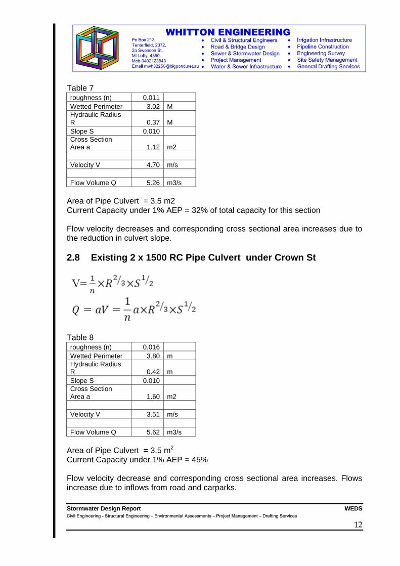
Table 7 roughness (n) 0.011 Wetted Perimeter 3.02 M Hydraulic Radius R 0.37 M Slope S 0.010 Cross Section Area a 1.12 m2 Velocity V 4.70 m/s Flow Volume Q 5.26 m3/s
Area of Pipe Culvert = 3.5 m2 Current Capacity under 1% AEP = 32% of total capacity for this section Flow velocity decreases and corresponding cross sectional area increases due to the reduction in culvert slope. 2.8 Existing 2 x 1500 RC Pipe Culvert under Crown St
Table 8 roughness (n) 0.016 Wetted Perimeter 3.80 m Hydraulic Radius R 0.42 m Slope S 0.010 Cross Section Area a 1.60 m2 Velocity V 3.51 m/s Flow Volume Q 5.62 m3/s
Area of Pipe Culvert = 3.5 m2 Current Capacity under 1% AEP = 45% Flow velocity decrease and corresponding cross sectional area increases. Flows increase due to inflows from road and carparks.
Stormwater Design Report WEDS Civil Engineering - Structural Engineering – Environmental Assessments – Project Management – Drafting Services
13
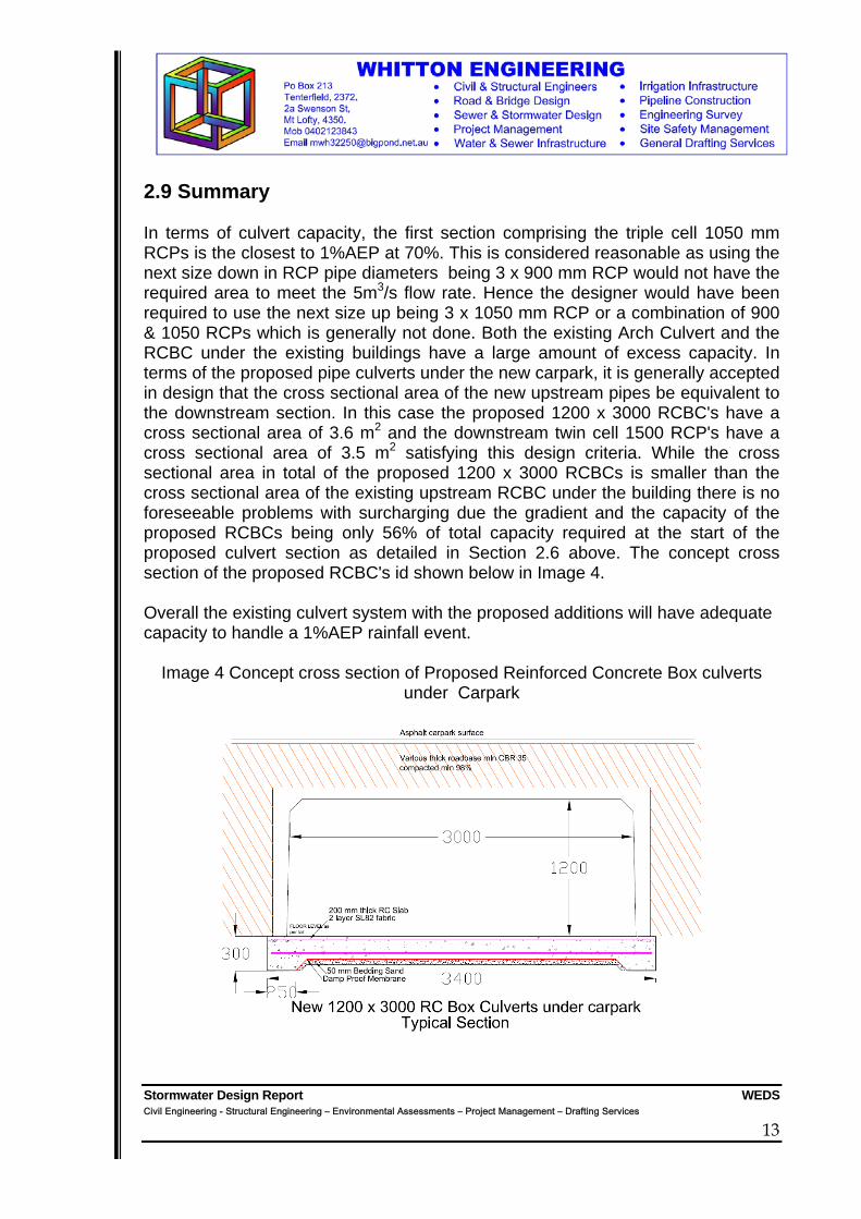
2.9 Summary In terms of culvert capacity, the first section comprising the triple cell 1050 mm RCPs is the closest to 1%AEP at 70%. This is considered reasonable as using the next size down in RCP pipe diameters being 3 x 900 mm RCP would not have the required area to meet the 5m3/s flow rate. Hence the designer would have been required to use the next size up being 3 x 1050 mm RCP or a combination of 900 & 1050 RCPs which is generally not done. Both the existing Arch Culvert and the RCBC under the existing buildings have a large amount of excess capacity. In terms of the proposed pipe culverts under the new carpark, it is generally accepted in design that the cross sectional area of the new upstream pipes be equivalent to the downstream section. In this case the proposed 1200 x 3000 RCBC's have a cross sectional area of 3.6 m2 and the downstream twin cell 1500 RCP's have a cross sectional area of 3.5 m2 satisfying this design criteria. While the cross sectional area in total of the proposed 1200 x 3000 RCBCs is smaller than the cross sectional area of the existing upstream RCBC under the building there is no foreseeable problems with surcharging due the gradient and the capacity of the proposed RCBCs being only 56% of total capacity required at the start of the proposed culvert section as detailed in Section 2.6 above. The concept cross section of the proposed RCBC's id shown below in Image 4. Overall the existing culvert system with the proposed additions will have adequate capacity to handle a 1%AEP rainfall event.
Image 4 Concept cross section of Proposed Reinforced Concrete Box culverts under Carpark

Stormwater Design Report WEDS Civil Engineering - Structural Engineering – Environmental Assessments – Project Management – Drafting Services
14
3 Part 2 Draft Stormwater Drainage for New Development This Section of the report will evaluate the proposed development and supply a draft stormwater drainage layout for the roof and carpark. Currently the existing stormwater from the site discharges to (a) Rouse Street Kerb & Gutter (RStK&G) (b) into an existing main which runs under the BILO complex (BILO main) (c) Directly into the RCBC under the existing building (ExRCBC) (d) Onto Miles Street and into existing Stormwater Pits which discharge into the ExRCBC (MStPits) (e) Into the open channel drain section to the West of the existing building Individual roof sections have been grouped together into larger units depending upon where they discharge to as detailed above. Carpark areas have been broken down based on concept areas flowing to each Pit as shown on WEDS 2123 Sheet SW.1 3.1 Methodology Roof Calculation of Roof Area and application of applicable multiplier from AS3500.3.2 5 min rainfall intensity for Tenterfield ARI 20 years = 169 mm Gutters assumed 8000 sq mm and gutter slope 1:500 All downpipes to be 100 mm Discharge Calculated Surface Areas Calculation of Area 5 min rainfall intensity for Tenterfield ARI 20 years = 169 mm Pits minimum 600 x 600 Discharge to Pit calculated Pit to Pit volumes calculated including cumulative totals All pipes laid at 1:100 min Pipe sizes identified Total discharges calculated

Stormwater Design Report WEDS Civil Engineering - Structural Engineering – Environmental Assessments – Project Management – Drafting Services
15
3.2 Results Table 9 shows the roof areas and the calculated discharge and the location of the discharge. Table 10 contains the data for the carpark areas. Table 11 is a summary of the Pipe sizes required. Table 9 Roof Stormwater Data
Roof Area (m2) Discharge(
l/s) Discharge Location R1 414 21.5 Ex BILO Main R2 427 22.2 Rouse St K & G R3 508 26.4 Rouse St K & G R4 167 8.7 Miles St Ex RCBC R5 269 14.0 Pit 4 R6 414 21.5 Miles St Ex RCBC R7 414 21.5 Pit 5 R8 200 10.4 Pit 9
Table 10 Carpark Area Stormwater Data
Carpark Area Area (m2)
Discharge( l/s) Discharge Location
A1 550 25.8 PIT 1 A2 513 24.1 PIT 2 A3 663 31.0 PIT 3 A4 697 32.7 PIT 4 A5 435 20.4 PIT 6 A6 100 5.0 PIT 7
Table 11 Stormwater Pipeline Data
Pipeline Pipe (mm) Discharge l/s Discharge Location
SWL1 150 25.8 PIT 1 TO PIT 2 SWL2 225 50.0 PIT 2 TO PIT 3 SWL3 300 81.0 PIT 3 TO NEW RCBC SWL4 225 46.7 PIT 4 TO PIT 5 SWL5 300 68.2 PIT 5 TO NEW RCBC SWL6 150 21.5 PIT 6 TO PIT 10 SWL7 100 5.0 PIT 7 TP PIT 8 SWL8 100 5.0 PIT 8 TO PIT 9 SWL9 150 15.4 PIT 9 TO PIT 10 SWL10 225 36.9 PIT 10 TO NEW RCBC

Stormwater Design Report WEDS Civil Engineering - Structural Engineering – Environmental Assessments – Project Management – Drafting Services
16
3.3 Summary The main aim of the concept stormwater design is to ensure that the new development does not result in a significant increase in the discharge volumes to a particular area. It is proposed to discharge as much stormwater as possible into the new RCBC under the proposed carpark with eventual discharge to the Crown St culverts. Based on the concept provided in WEDS 2123 Sheet SW.1 and with the data supplied above, it can be shown that the discharge locations have similar areas to the existing development. While it must be noted that the time of concentration will increase due to additional roof areas it is considered that no adverse impacts on the existing systems (in particular the Rouse Street pipeline network) will result. Detailed Design and Specification will be supplied as part of the conditions of the approved Development Application prior to a Construction Certificate being issued.

Stormwater Design Report WEDS Civil Engineering - Structural Engineering – Environmental Assessments – Project Management – Drafting Services
17
4 Part 3 Review of existing sewerage services and draft proposed connections layout. The existing sewerage infrastructure to 148 Rouse St comprises of a Tenterfield Shire Council 150 NB main which extends south under the existing BILO complex and terminates at an Inspection Opening (IO) at the rear of the existing workshop building on the site. The existing toilets and other facilities are connected in this location as shown on WEDS 21-23 SW.2 The Proposed development will require 4 (four) new Sewer connections as shown on WEDS 21-23 SW.2. Each new tenancy will require a new connection with the Cinema tenancy utilising the existing connection. The Child Care centre will require an extension to the main using a minimum 100 NB Mainline. Detailed Design and Specification will be supplied as part of the conditions of the approved Development Application prior to a Construction Certificate being issued.

Stormwater Design Report WEDS Civil Engineering - Structural Engineering – Environmental Assessments – Project Management – Drafting Services
18
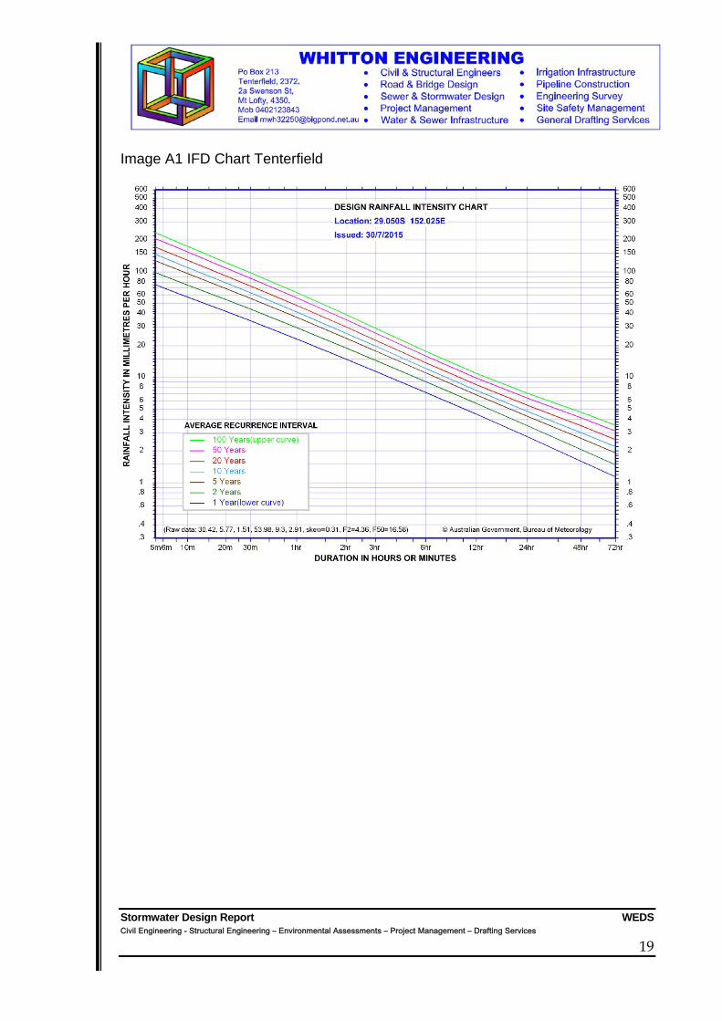
7. Appendix 1 – IFD DATA Tenterfield
Table A1 IFD Table for Tenterfield
Duration ARI minutes 5 20 100
5 126.79 169.47 230.596 118.51 158.06 214.648 105.60 189.9410 95.97 127.16 171.6412 88.36 157.2314 82.20 145.6415 79.47 140.5116 77.01 135.9018 72.65 127.7620 68.78 90.17 120.56
Table A2: Runoff Coefficients for
Tenterfield
Fraction Runoff Coefficient impervious
C10 C2 C100 f 0 0.32 0.27 0.38
0.1 0.38 0.32 0.45 0.2 0.43 0.37 0.52 0.3 0.49 0.42 0.59 0.4 0.55 0.47 0.66 0.5 0.61 0.52 0.73 0.6 0.67 0.57 0.80 0.7 0.73 0.62 0.87 0.8 0.78 0.67 0.94 0.9 0.84 0.72 1.00 1 0.90 0.77 1.00
Stormwater Design Report WEDS Civil Engineering - Structural Engineering – Environmental Assessments – Project Management – Drafting Services
19
Image A1 IFD Chart Tenterfield