Embed Size (px)
Citation preview

MASKING TAPE
Interior
FS-42 SCREWSACTORY
4 3/4" 4 3/4" 4 3/4"
D-69AS-6
D-24D-6
3 4
FG-5109 FILLER
FG-5121/FG-5155
CW-998 BULB GASKETINSTALL CW-998 BULBGASKETS ON EXTERIOR INTERIOR SIDE OF MULLIONS.
1 7/16" 1 7/16"
LEVELING SCREW
SIDE BLOCK
GLASS SETTING BLOCK
SIDE BLOCK
FS-8 (TYP.)PART #10223
CW-998 EXTERIOR & INTERIOR
TACKY TAPE
FG-5110
SCHNEE MOOREHEADSM-5601 1/8" X 1/2" TACKYTAPE. VW PART #4666
FG-511
TACKY TAPE
FG-5109
ANCHORING
CAP SEAL
JAMB
1"
1"M
ULLI
ON L
ENG
TH
DRILL .228 DIA. HOLE (#1 DRILL)AS SHOWN FOR FS-381/4-20 X 1/2" HH TYPE FSELF TAPPING
9955
4-9/16"
1/4"
1-1/4"
2-9/32"
StormMaxFG-5000
IMPACT RESISTANTSYSTEM FOR
HIGH VELOCITYHURRICANE ZONES
INSTALLATION AND
GLAZING MANUAL
2nd EditionMarch 2007

General Information...................................................................................................Page 3
Frame Fabrication (Wet Glaze/Dry-Glaze Option).................................................Page 4-9
Frame Assembly (Wet Glaze/Dry-Glaze Option)................................................Page 22-23
Frame Installation (Wet Glaze/Dry-Glaze Option)..............................................Page 24-27
Glazing (Wet Glaze Option)................................................................................Page 28-29
Glazing (Dry Glaze Option).................................................................................Page 30-31
Preparation of Door Frame......................................................................................Page 32
Installation of Door Frame........................................................................................Page 33
Door Preparation and Glazing............................................................................Page 34-35
Entrance Door Frame Installation............................................................................Page 36
FG-5000 Parts....................................................................................................Page 37-39
FG5000 INSTALLATION INSTRUCTIONSThese instructions are to be used for typical installations. Reference shop drawings for special notations on installations and glazing.
TABLE OF CONTENTS
March 20072
F G - 5 0 0 0 I M P A C T R E S I S T A N T S Y S T E M

GENERAL INFORMATION
1. GENERAL INFORMATION:Vistawall FG-5000 (2-1/2" x 5") hurricane impact resistant system represents the latest in product development technol-ogy. This system was especially designed to meet the stringent requirements of Dade County and Florida Building Codes as well as the International Building Code for glass and glazing systems. FG-5000 successfully passed a series of large missile impact and cyclic wind test with a variety of impact-resistant glass.
2. BUILDING CODES:Vistawall does not control the application nor selection of its product configurations, sealant or glazing materials and assumes no responsibility thereof. It is the responsibility of the owner, architect, and installer to make these selectionsin strict compliance with applicable laws and building codes.
3. STRUCTURAL SEALANTS:Both DOW 795 and 995 structural sealants were used on the FG-5000 test specimen for glass to metal adhesion approved by Dade County. To comply with Dade County and Florida Building Code Protocols, DOW 795 and 995 sealant must be used for glass to metal adhesion with FG-5000.
4. PERIMETER SEALANTS:Due to varying job conditions, all perimeter sealants used should be approved by the sealant manufacturer to ensure the sealant will function for the conditions shown on these instructions and shop drawings. Sealants must be compatible with all surfaces in which adhesion is required, including other sealants surfaces. Use primers where directed by sealant manufacturer. Be sure to properly store sealants at recommended temperature and check container for remainder of shelf life before using. VULKEM 921 polyurethane was the perimeter sealant used on the FG-5000 test specimen approved by Dade County.
5. MATERIAL HANDLING: A. SHOP 1. Cardboard wrapped or paper interleaved material must be kept dry. 2. Check arriving materials for quantity and keep record of where various materials are stored.
B. JOB SITE 1. Material at job site must be stored in a safe place well removed from possible damage by other trades. 2. Cardboard wrapped or paper interleaved materials must be kept dry. 3. Keep record of where various materials are stored. 4. Protect materials after erection. Cement, plaster, and other alkaline solutions are very harmful to the finish.
C. CLEANING Aluminum shall be cleaned with plain water containing a mild detergent, or a petroleum product such as white gasoline, kerosene, or distillate. No abrasive agent shall be used.
6. GENERAL CONSTRUCTION NOTES A. Study these instructions, shop drawings, erection drawings, and architectural drawings, before starting any work. B. All materials are to be installed, plumb, and level. C. All work should start from an established benchmark and column centerlines established by the architect and the general contractor. D. Completely check construction which will receive your materials against contract documents. Notify the general contractor by letter of any discrepancies before proceeding with your work since this constitutes acceptance of work by other trades. E. Protect all aluminum to be placed directly in contact with uncured masonry or incompatible materials with a heavy coat of zinc chromate or bituminous paint. F. Follow installation and glazing instructions. G. After sealant is set and a representative amount of the wall has been glazed (500 square feet or more), run a water hose test to check installation. On large jobs, hose test should be repeated during glazing operation. Test should be conducted in accordance with AAMA 501.2 specifications.
March 2007 3
F G - 5 0 0 0 I M P A C T R E S I S T A N T S Y S T E M
GENERAL INFORMATION

Establish Frame Size & Cut Metal to Length
STEP 1Measure width of rough opening.A. Measure opening at bottom.B. Measure opening at center.C. Measure opening at top.The frame width will be the smallest dimension less 1/2" allowing for a min 1/4" caulk joint at each jamb.
NOTE: Maximum caulk joint for Dade County, FL. installation is 1/4"
Repeat process to determine frame height.A. Beginning on left side of opening, measure dimension from top to bottom.B. Repeat at center.C. Repeat at right side of opening.The frame height will be the smallest dimension less 5/8" to allow for subsill and a 1/4" caulk jointat the head and sill.
March 20074
F G - 5 0 0 0 I M P A C T R E S I S T A N T S Y S T E M
FRAME FABRICATION FOR PANELIZED/PRE-GLAZE OPTION

Establish Frame Size & Cut Metal to Length
STEP 1Measure width of rough opening.A. Measure opening at bottom.B. Measure opening at center.C. Measure opening at top.The frame width will be the smallest dimension less 1/2" allowing for a min 1/4" caulk joint at each jamb.
NOTE: Maximum caulk joint for Dade County, FL. installation is 1/4"
Repeat process to determine frame height.A. Beginning on left side of opening, measure dimension from top to bottom.B. Repeat at center.C. Repeat at right side of opening.The frame height will be the smallest dimension less 5/8" to allow for subsill and a 1/4" caulk jointat the head and sill.
1"
TOP OF HORIZONTAL
"F" (.257" DIA.)DRILL THRU TYP.
FG-5109 FILLER
FG-5121/FG-5155
CW-998 BULB GASKETINSTALL CW-998 BULBGASKETS ON EXTERIOR &INTERIOR SIDE OF MULLIONS.
NOTE:Gasket reglet isalways to exterior.
STEP 2Cut members to size.Cut subsill flashing to frame dimension plus 1/4". Subsill at entrance locationsbutt tight against door jamb(s) and is cut 1/8" longer than width of side light(s) oneither side of door frame.Wall jambs and intermediate vertical mullions are cut to frame height.Horizontal members are cut to D.L.O.Snap-on glass stops are cut D.L.O. minus(-) 1/16"
STEP 3Drill or punch holes in verticals for attaching horizontals.
1-7/16" 1-7/16"
2-1/2"7/8"
1/4"
1-1/4"
1-1/4"7/8"
2-1/2"
7/8"2-1/2"
1-1/4"
1/4"
March 2007 5
F G - 5 0 0 0 I M P A C T R E S I S T A N T S Y S T E M
FRAME FABRICATION FOR PANELIZED/PRE-GLAZE OPTION

1"
1"
MUL
LION
LEN
GTH
DRILL .228 DIA. HOLE (#1 DRILL)AS SHOWN FOR FS-381/4-20 X 1/2" HH TYPE FSELF TAPPING
ATTACH STEEL WITHFS-38 STS FASTENER 1" FROM EACH END OFMULLION.
99559956
STEEL FOR ALTERNATEWALL JAMB ONLY
Fabricate steel reinforcement where required.
DOOR JAMB AND ALTERNATE WALL JAMBINTERM. VERTICAL
STEEL ATTACHMENT AT
4-9/16"
1/4"
1-1/4"
2-9/32"
4-11/16"
1-9/32"
2-11/32"
March 20076
F G - 5 0 0 0 I M P A C T R E S I S T A N T S Y S T E M
FRAME FABRICATION FOR PANELIZED/PRE-GLAZE OPTION

March 2007 7
F G - 5 0 0 0 I M P A C T R E S I S T A N T S Y S T E M
FRAME FABRICATION FOR PANELIZED/PRE-GLAZE OPTION
2"2" AS REQ'D SEE CHARTS (TYP.) AS REQ'D
AS REQ'D SEE CHARTS (TYP.)2" 2"AS REQ'D
Fabricate head and sill for anchor holes. Number of anchors vary based on substrate material. Reference anchor charts for number of anchor holes and locations for each substrate. First hole is always 2" from end. Each additional fastener hole is at required minimum spacing between fastener as shown in anchor charts.
Bottom view of FG-5110 head
Top view of FG-5112 SILL
FG-5110
FG-5112
11/16
"11/
16"

NOTE: Steel reinforcedjambs do not need to beanchored to substrate.
NOTE: Install 18" long FG-5000-FP-12 anchor plate @ mullion midpoint and sill intersection. FG-2188 can be usedbetween anchor plates to support caulking back up.
Fabricate wall jamb for anchor holes. Number of anchors vary based on substratematerial. (Reference Anchor Charts)
FG-5121 JAMBWITH FG-5109AND 9956STL.
MUL
LION
LEN
GTH
MUL
LION
LEN
GTH
FG-5161 JAMB
ANCHOR HOLESNOTE:IF ANCHOR HOLE IS ATINTERSECTION OFINTERMEDIATE HORIZONTALJUST LOCATE AS CLOSETO CHARTED DIMENSIONSAS POSSIBLE.CHECK ANCHOR CHARTFOR SPACING ANDQUANTITY BASED ONSUBSTRATE.
March 20078
F G - 5 0 0 0 I M P A C T R E S I S T A N T S Y S T E M
FRAME FABRICATION FOR PANELIZED/PRE-GLAZE OPTION
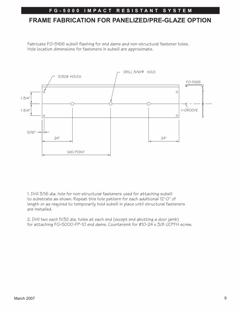
Fabricate FG-5166 subsill flashing for end dams and non-structural fastener holes.Hole location dimensions for fasteners in subsill are approximate.
1. Drill 3/16 dia. hole for non-structural fasteners used for attaching subsillto substrate as shown. Repeat this hole pattern for each additional 12'-0" oflength or as required to temporarily hold subsill in place until structural fastenersare installed.
2. Drill two each 5/32 dia. holes at each end (except end abutting a door jamb)for attaching FG-5000-FP-10 end dams. Countersink for #10-24 x 3/8 UCPFH screw.
5/32 HOLESDRILL 3/16" HOLE
FG-5166
V-GROOVE
1-3/4"
1-3/4"
5/16"24"
MID-POINT
24"
CL
March 2007 9
F G - 5 0 0 0 I M P A C T R E S I S T A N T S Y S T E M
FRAME FABRICATION FOR PANELIZED/PRE-GLAZE OPTION

Match drill holes in subsill end damwith 5/32" drill. Attach withtwo each #10-24 x 3/8" screwsas shown.
Ø
Apply SM-5601 tacky tape to end dams as shown and stickto the ends of subsill
FG-5000-FP-10END DAM
FG-5000-FP-10
FG-5166 SUBSILL
SM-5601TACKY TAPE
TACKY TAPE
#10-24 X 3/8 UCPFH
5/16"
March 200710
F G - 5 0 0 0 I M P A C T R E S I S T A N T S Y S T E M
FRAME ASSEMBLY FOR PANELIZED/PRE-GLAZE OPTION
March 2007 11
F G - 5 0 0 0 I M P A C T R E S I S T A N T S Y S T E M
FRAME ASSEMBLY FOR PANELIZED/PRE-GLAZE OPTION
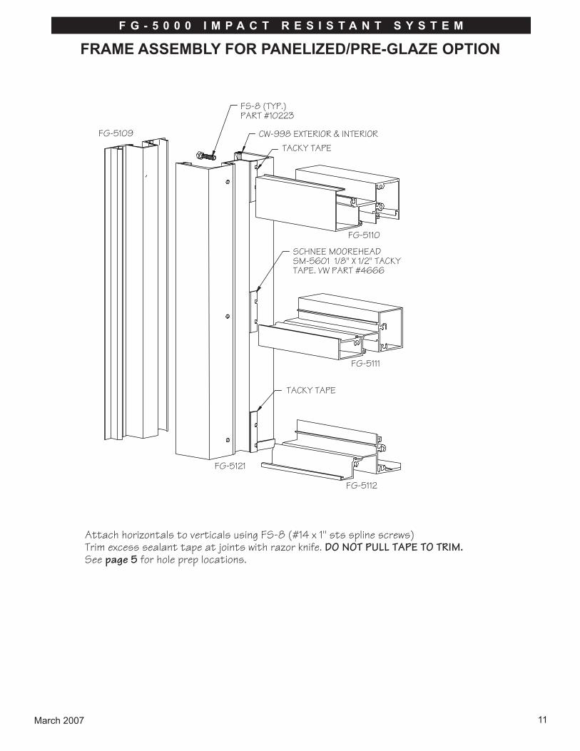
Attach horizontals to verticals using FS-8 (#14 x 1" sts spline screws)Trim excess sealant tape at joints with razor knife. DO NOT PULL TAPE TO TRIM.See page 5 for hole prep locations.
FS-8 (TYP.)PART #10223
CW-998 EXTERIOR & INTERIORTACKY TAPE
FG-5110
SCHNEE MOOREHEADSM-5601 1/8" X 1/2" TACKYTAPE. VW PART #4666
FG-5111
TACKY TAPE
FG-5112
FG-5121
FG-5109

March 200712
F G - 5 0 0 0 I M P A C T R E S I S T A N T S Y S T E M
FRAME INSTALLATION FOR PANELIZED/PRE-GLAZE OPTION
Position fabricated subsill with end dams into opening. Center into opening allowingshim space at jambs.
SHIM
FG-5166
FG-5000-FP-10END DAM
SHIMTIGHTLY
NOTE: APPLY DOW 795/995SEALANT JUST PRIOR TO INSTALLING FRAME PANELS
CAP SEAL ALL FASTENERHEADS PENETRATING SUBSILLFLASHING WITH DOW 795/995SEALANT
Shim beneath subsill to be a maximum of 1/4". Attach subsill flashingto structure with non-structural fasteners using attachment holesshown on page 9.
Wedge shims tightly between end dams and jamb substrate at each end prior toinstalling frame panels. These shims prevent the end dams from being dislodgedwhile frame panels are being installed. Completely seal end dams as shown.
Run a continuous bead of Dow 795 or 995 sealant along the full length of the subsill as shown above just prior to installing frame panels. Do not allowsealant to harden prior to installing frame panels.
SEALANT TORUN CONT.
SEALANT NOTREQUIRED.
CAP SEAL
APPLY SEALANTINTO ANCHOR HOLEPRIOR TO ANCHORING
CAP SEAL
FACE OF VERTICAL
HEAD SILL
A B
PUSH MULLIONTIGHT TOSUB SILL
SEALANT OVER TEMPSCREWS SET SILL MEMBER
IN BED OF SEALANT
SECONDARY SEALPRIMARY SEAL 1/4" GAP
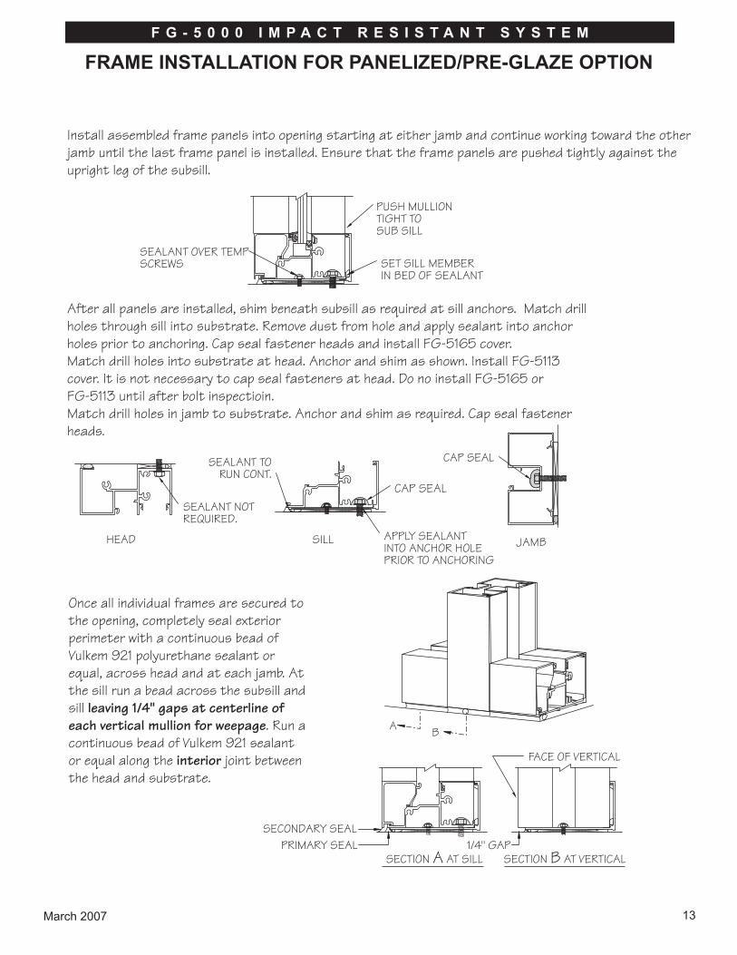
Once all individual frames are secured to the opening, completely seal exterior perimeter with a continuous bead of Vulkem 921 polyurethane sealant or equal, across head and at each jamb. At the sill run a bead across the subsill and sill leaving 1/4" gaps at centerline of each vertical mullion for weepage. Run a continuous bead of Vulkem 921 sealant or equal along the interior joint between the head and substrate.
Install assembled frame panels into opening starting at either jamb and continue working toward the other jamb until the last frame panel is installed. Ensure that the frame panels are pushed tightly against the upright leg of the subsill.
JAMB
After all panels are installed, shim beneath subsill as required at sill anchors. Match drill holes through sill into substrate. Remove dust from hole and apply sealant into anchor holes prior to anchoring. Cap seal fastener heads and install FG-5165 cover.Match drill holes into substrate at head. Anchor and shim as shown. Install FG-5113 cover. It is not necessary to cap seal fasteners at head. Do no install FG-5165 or FG-5113 until after bolt inspectioin.Match drill holes in jamb to substrate. Anchor and shim as required. Cap seal fastener heads.
SECTION A AT SILL SECTION B AT VERTICAL
March 2007 13
F G - 5 0 0 0 I M P A C T R E S I S T A N T S Y S T E M
FRAME INSTALLATION FOR PANELIZED/PRE-GLAZE OPTION

INTERIOR SEALANT AT SILLAND JAMB
CAP SEAL
Starting from the bottom, seal up the jamb to the interior to a height of 3".It is not necessary to seal the balance of the jamb on the interior or beneaththe interior side of the subsill flashing except for cosmetic reasons.
March 200714
F G - 5 0 0 0 I M P A C T R E S I S T A N T S Y S T E M
FRAME INSTALLATION FOR PANELIZED/PRE-GLAZE OPTION

March 2007 15
F G - 5 0 0 0 I M P A C T R E S I S T A N T S Y S T E M
GLAZING FOR PANELIZED/PRE-GLAZE OPTION
FG-5000-FP-5/6 (HANDED)WATER DIVERTER SET IN BEDOF SEALANT. INSTALL AFTER GLAZING LOWER LITES.
FG-5105 SETTING BLOCK
FG-1133 GASKET
V2110 GASKET
Make sure spacer gasketis positioned in pocketsas shown.
FG-5109FG-5170
FG-5110FG-5111FG-5112FG-5161
FG-5108FG-5121FG-5155
V-2110
Remove all debris from glazing pockets to prevent blockage of weeps/drains. Clean backside of glazing pockets with isopropyl alcohol prior to installation of V2110 spacer gasket to remove all dirt and cutting oils.
It is recommended that the interior spacer gasket be installed just prior to glazing.Install two each 4" long setting blocks at 1/4 point of horizontal length in sill and intermediate horizontals.

2"
2"
MASKING TAPE
NON-STRUCTURALFASTENER
STRUCTURAL FASTENER(REF. ANCHOR CHARTS)
FG-1133 GASKET
APPLY DOW 795/995 SEALANT
FIG. B
FIG. A
PULL GASKETS BACK AT ALLCORNERS AS SHOWN
PUSH GASKETS BACK INTO REGLET
Interior
Glaze from bottom to top. Install water diverters as shown on page 15 after lowerlite is in position.Install exterior glass stops.Install exterior FG-1133 glazing gaskets as shown on page 15.Cut gaskets a minimum of 1/8" per foot longer than daylight opening to provide foradequate compression. Pull gasket from pocket as shown in FIG. B below.Clean gaskets 2" from each end with isopropyl alcohol. Apply Dow 795/995 sealant(FIG. B) as shown. Push gaskets into reglet.Mask off glass and aluminum with 2" wide low adhesion masking tape. Fill cavitywith Dow 795 or 995 sealant as shown below (FIG. A) and immediately tool.Remove masking tape immediately after installation of silicone taking care not todamage or pull silicone from the cavity.
9/16"
March 200716
F G - 5 0 0 0 I M P A C T R E S I S T A N T S Y S T E M
GLAZING FOR FOR PANELIZED/PRE-GLAZE OPTION

Establish Frame Size & Cut Metal to Length
STEP 1Measure width of rough opening.A. Measure opening at bottom.B. Measure opening at center.C. Measure opening at top.The frame width will be the largest dimension less 1" allowing for a max 1/2" caulk joint at each jamb.
NOTE: Maximum caulk joint for Dade County, FL. installation is 1/2"
Repeat process to determine frame height.A. Beginning on left side of opening, measure dimension from top to bottom.B. Repeat at center.C. Repeat at right side of opening.The frame height will be the largest dimension less 1 1/8" to allow for subsill and a 1/4" caulk jointat the head and sill.
March 2007 17
F G - 5 0 0 0 I M P A C T R E S I S T A N T S Y S T E M
FRAME FABRICATION WET AND DRY GLAZE FRAMING

STEP 2Cut members to size.Cut subsill flashing to frame dimension plus 1/4". Subsill at entrance locations butt tight against door jamb(s) and is cut 1/8" longer than width of side light(s) on either side of door frame.Wall jambs and intermediate vertical mullions are cut to frame height.Horizontal members are cut to D.L.O.Snap-on glass stops are cut D.L.O. minus(-) 1/16"
STEP 3Drill or punch holes in verticals for attaching horizontals.
TOP OF HORIZONTAL
“F (.257" DIA.)DRILL THRU TYP.
FG-5196 FILLER
FG-5193
1/4"
1 1/4
"
7/8
"
21/2
"
1/4"
1 1/4
"
21/2
"
7/8
"
1 15/16" 1 15/16"
2 1/2
" 1"1 1
/4"
7/8
"
March 200718
F G - 5 0 0 0 I M P A C T R E S I S T A N T S Y S T E M
FRAME FABRICATION WET AND DRY GLAZE FRAMING

1"
1"
MUL
LIO
N L
ENG
TH
DRILL .228 DIA. HOLE (#1 DRILL)AS SHOWN FOR FS-381/4-20 X 1/2" HH TYPE FSELF TAPPING
ATTACH STEEL WITHFS-38 STS FASTENER 1" FROM EACH END OFMULLION.
99559956
STEEL FOR ALTERNATEWALL JAMB ONLY
Fabricate steel reinforcement where required.
STEEL ATTACHMENT ATINTERM. VERTICAL
DOOR JAMB AND ALTERNATE WALL JAMB
4-9/16"
1/4"
1-1/4"
2-9/32"
4-11/16"
1-9/32"
2-11/32"
March 2007 19
F G - 5 0 0 0 I M P A C T R E S I S T A N T S Y S T E M
FRAME FABRICATION WET AND DRY GLAZE FRAMING

Fabricate head and sill for anchor holes. Number of anchors vary based on substrate material. Reference anchor charts for number of anchor holes and locations for each substrate. First hole is always 2" from end. Each additional fastener hole is at required minimum spacing.
FG-5191
2" 2"
2 1/2
"
AS REQ'D SEE CHARTS (TYP.) AS REQ'D
March 200720
F G - 5 0 0 0 I M P A C T R E S I S T A N T S Y S T E M
FRAME FABRICATION WET AND DRY GLAZE FRAMING

MUL
LION
LEN
GTH
MUL
LION
LEN
GTH
FG-5201 JAMB
ANCHOR HOLESNOTE:IF ANCHOR HOLE IS ATINTERSECTION OFINTERMEDIATE HORIZONTALJUST LOCATE AS CLOSETO CHARTED DIMENSIONSAS POSSIBLE.CHECK ANCHOR CHART FOR SPACING ANDQUANTITY BASED ONSUBSTRATE.
FG-5193 JAMBWITH FG-5196AND 9956STL.
NOTE: STEEL REINFORCEDJAMBS DO NOT NEED TO BEANCHORED TO SUBSTRATE.
Fabricate wall jamb for anchor holes. Number of anchors vary based on substrate material. Reference anchor charts for locations for each substrate.
NOTE: Install 18" long FG-5000-FP-12 anchor plate @ mullion midpoint and sill intersection. FG-2188 can be usedbetween anchor plates to support caulking back up.
CAUTION: Shallow pockets cannot face each other.
FG-5167 FLAT FILLER
March 2007 21
F G - 5 0 0 0 I M P A C T R E S I S T A N T S Y S T E M
FRAME FABRICATION WET AND DRY GLAZE FRAMING

FS-8 (TYP.)PART #10223
SCHNEE MOOREHEADSM-5601 1/8" X 1/2" TACKYTAPE. VW PART #4666
NOTE: Install FG-5185 interior spacer gasket (wet glaze)and FG-5946 (dry glaze) into framing prior to assembly.
SCHNEE MOOREHEADSM-5601 1/8" X 1/2" TACKYTAPE. VW PART #4666
Attach horizontals to verticals using FS-8 (#14 x 1" sts spline screws)Trim excess sealant tape at joints with razor knife. DO NOT PULL TAPE TO TRIM.See sheet 15 for hole prep locations.
FG-5191
FG-5189
FG-5191FG-5193
FG-5196
March 200722
F G - 5 0 0 0 I M P A C T R E S I S T A N T S Y S T E M
FRAME ASSEMBLY WET AND DRY GLAZE FRAMING

Apply SM-5601 tacky tape to end dams as shown and stickto the ends of subsill.
Match drill holes in subsill end dam with 5/32"Ø drill. Attach with two each #10-24 x 3/8" screwsas shown.
FG-5000-FP-10END DAM
SM-5601TACKY TAPE
FG-5180 SUBSILL
TACKY TAPE
FG-5000-FP-10
#10-24 X 3/8 UCPFH
5/16"
March 2007 23
F G - 5 0 0 0 I M P A C T R E S I S T A N T S Y S T E M
FRAME ASSEMBLY WET AND DRY GLAZE FRAMING

SHIM
FG-5180
FG-5000-FP-10END DAM
SHIMTIGHTLY
NOTE: APPLY DOW 795/995SEALANT JUST PRIOR TO INSTALLING FRAME PANELS
CAP SEAL ALL FASTENERHEADS PENETRATING SUBSILLFLASHING WITH DOW 795/995SEALANT
Position fabricated subsill with end dams into opening. Center into opening allowing shim space at jambs.
Shim beneath subsill to be a maximum of 1/2". Attach subsill flashing to structure with non-structural fasteners using attachment holes, shown on page 19.
Wedge shims tightly between end dams and jamb substrate at each end prior to installing frame panels. These shims prevent the end dams from being dislodged while frame panels are being installed. Completely seal end dams as shown.
Run a continuous bead of Dow 795 or 995 sealant along the full length of the sub sill channel as shown above just prior to installing frame panels. Do not allow sealant to harden prior to installing frame panels. Remove excess sealant after panels are installed.
March 200724
F G - 5 0 0 0 I M P A C T R E S I S T A N T S Y S T E M
FRAME INSTALLATION WET AND DRY GLAZE FRAMING

SEAL WITH A NON-SKINNING,NON-HARDENING SEALANT.FILL BREAK IN FLASHING AND SEAL UNDER SPLICE. DOW 795 OR EQUAL
.040"x2"x3" ALUMINUM SPLICEFG-5180
MAKE SURE 1/4"x1/4" VOID LEFT @ CORNER OF SUB-SILL IS COMPLETELY SEALED
1/4"
.040"x4 1/2"x3" ALUMINUM SPLICE
March 2007 25
F G - 5 0 0 0 I M P A C T R E S I S T A N T S Y S T E M
FRAME INSTALLATION SUB-SILL SPLICE WET AND DRY GLAZE FRAMING

PUSH MULLIONTIGHT TOSUB SILL
CAP SEAL
CAP SEAL
APPLY SEALANTINTO ANCHOR HOLEPRIOR TO ANCHORING
SEALANT NOTREQUIRED.
SEAL OVERNON-STRUCTURAL SCREWS
Install assembled frame panels into opening starting at either jamb and continue working toward the other jamb until the last frame panel is installed. Ensure that the frame panels are pushed tight against the upright leg of the subsill. Remove excess sealant after panels are installed.
After all panels are installed, shim beneath subsill as required at fasteners.Match drill holes through sill into substrate. Remove dust from holes. Apply sealant into anchor holes prior to anchoring. Cap seal fastener heads.Match drill holes into substrate at head. Anchor and shim as shown. It is not necessary to cap seal fasteners at head.Match drill holes in jamb to substrate. Anchor and shim as required. Cap seal fastener heads.
Once all individual frames are secured to the opening, then completely seal with a continuous bead of Vulkem 921 polyurethane sealant or equal, across head and at each jamb. At the sill run a bead across the subsill.
HEAD SILL JAMB
March 200726
F G - 5 0 0 0 I M P A C T R E S I S T A N T S Y S T E M
FRAME INSTALLATION WET AND DRY GLAZE FRAMING

PUSH MULLIONTIGHT TOSUB SILL
CAP SEAL
CAP SEAL
APPLY SEALANTINTO ANCHOR HOLEPRIOR TO ANCHORING
SEALANT NOTREQUIRED.
SEAL OVERNON-STRUCTURAL SCREWS
Install assembled frame panels into opening starting at either jamb and continue working toward the other jamb until the last frame panel is installed. Ensure that the frame panels are pushed tight against the upright leg of the subsill. Remove excess sealant after panels are installed.
After all panels are installed, shim beneath subsill as required at fasteners.Match drill holes through sill into substrate. Remove dust from holes. Apply sealant into anchor holes prior to anchoring. Cap seal fastener heads.Match drill holes into substrate at head. Anchor and shim as shown. It is not necessary to cap seal fasteners at head.Match drill holes in jamb to substrate. Anchor and shim as required. Cap seal fastener heads.
Once all individual frames are secured to the opening, then completely seal with a continuous bead of Vulkem 921 polyurethane sealant or equal, across head and at each jamb. At the sill run a bead across the subsill.
HEAD SILL JAMB
March 2007 27
F G - 5 0 0 0 I M P A C T R E S I S T A N T S Y S T E M
FRAME INSTALLATION WET AND DRY GLAZE FRAMING
Starting from the bottom, seal up the jamb at the interior to a height of 3".It is not necessary to seal the balance of the jamb on the interior or beneath the interior side of the sub sill flashing other than for cosmetic reasons.
INTERIOR SEALANT AT SILLAND JAMB
CAP SEAL

Remove all debris from glazing pockets to allow for proper drainage.
FG-5100-FP-5WATER DIVERTER SET IN BEDOF SEALANT. INSTALL AFTER GLAZING LOWER LITES.
FG-5199 SETTING BLOCK
FG-1133 GASKET
FG-5185 SPACER GASKETPRE-INSTALL
March 200728
F G - 5 0 0 0 I M P A C T R E S I S T A N T S Y S T E M
GLAZING WET GLAZE OPTION
9/16
"
2"
2"
MASKING TAPE
NON-STRUCTURALFASTENER
STRUCTURAL FASTENER(REF. ANCHOR CHARTS)
FIG. A
PULL GASKETS BACK AT ALLCORNERS AS SHOWN
APPLY DOW 995 ORTREMCO SPECTREM 2SEALANT; PUSH GASKETSBACK INTO REGLET
FG-1133 EXTERIOR GASKET
FIG. B
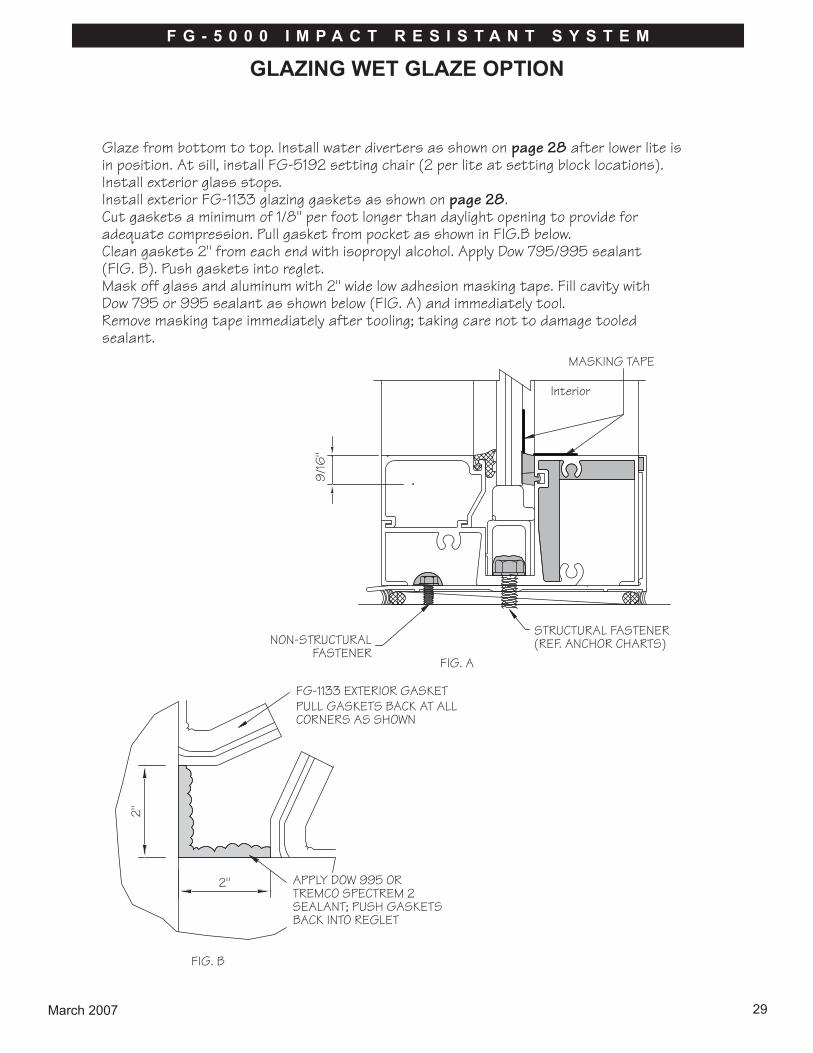
Glaze from bottom to top. Install water diverters as shown on page 28 after lower lite is in position. At sill, install FG-5192 setting chair (2 per lite at setting block locations).Install exterior glass stops.Install exterior FG-1133 glazing gaskets as shown on page 28.Cut gaskets a minimum of 1/8" per foot longer than daylight opening to provide for adequate compression. Pull gasket from pocket as shown in FIG.B below.Clean gaskets 2" from each end with isopropyl alcohol. Apply Dow 795/995 sealant (FIG. B). Push gaskets into reglet.Mask off glass and aluminum with 2" wide low adhesion masking tape. Fill cavity with Dow 795 or 995 sealant as shown below (FIG. A) and immediately tool.Remove masking tape immediately after tooling; taking care not to damage tooled sealant.
Interior
March 2007 29
F G - 5 0 0 0 I M P A C T R E S I S T A N T S Y S T E M
GLAZING WET GLAZE OPTION

FG-5100-FP-5WATER DIVERTER SET IN BEDOF SEALANT. INSTALL AFTER GLAZING LOWER LITES.
FG-5199 SETTING BLOCK
5947 EXTERIOR GASKET
5946 INTERIOR GASKET
SEAL BETWEEN GASKETAT CORNER
Remove all debris from glazing pockets to allow proper drainage.
March 200730
F G - 5 0 0 0 I M P A C T R E S I S T A N T S Y S T E M
GLAZINGDRY GLAZE OPTION

9/16
"
2"
2"
NON-STRUCTURALFASTENER STRUCTURAL FASTENER
(REF. ANCHOR CHARTS)FIG. A
5947 EXTERIOR GASKETPULL GASKETS BACK AT ALLCORNERS AS SHOWN
APPLY DOW 995 ORTREMCO SPECTREM 2SEALANT; PUSH GASKETSBACK INTO REGLET
FIG. B
Glaze from bottom to top. Install water diverters as shown on page 30 after lower lite is in position. At sill, install FG-5192 setting chair (2 per lite at setting block locations).Install exterior glass stops.Install exterior 5947 glazing gaskets as shown on page 30.Cut gaskets a minimum of 1/8" per foot longer than daylight opening to provide for adequate compression. Pull gasket from pocket as shown in FIG.B below.Clean gaskets 2" from each end with isopropyl alcohol. Apply Dow 795/995 sealant (FIG. B). Push gaskets into reglet. 5946 gasket must be slid in before frame is assembled. Gasket intersections must be caulked with Dow 995/795 prior to setting glass.
March 2007 31
F G - 5 0 0 0 I M P A C T R E S I S T A N T S Y S T E M
GLAZING DRY GLAZE OPTION

1"D-134-2 PANICSTOP FOR PAIRSFACTORY INSTALLED
LOCATE ANCHOR HOLESAS SHOWN IN CHARTS(FIELD FABRICATED)
DRILL 7/32" CLEAR HOLE& COUNTERSINK 7/16"Ø FOR #12 F.H.
(FIELD FABRICATED)
1"
2 9/16"
All hardware back-up plates are installed in the frame at the factory. Door stops andtransom sash will have been cut to length and prepped in the factory.Stock transom frames are fabricated for a vertical frame size of 120". If youropening is smaller, cut the verticals and the sash down to the appropiate length.Leave a maximum 1/4" caulk joint at the head. The prep for the transom headhorizontal should be made using either a drill fixture or EZ-punch die sets for theSeries 5000 framing.
Review frame anchor charts for configuration and substrate for which the frame willbe attached. Drill anchor holes into FG-5168 door jamb, FG-5167 flat filler andTH-57 threshold as shown in charts. (Note: CW-998 bulb gasket is not requiredin the FG-5168 jamb at wall).
Attach frame portion of offset pivots to frame if applicable.Apply Schnee-Morehead SM-5601 1/8" x 1/2" tacky tape to joint intersections atdoor header or transom bar and transom head horizontal.Note: Keep tape away from screw splines.
Assemble frame and threshold with FS-8 spline screws or use alternate thresholdclips and fabricate two holes in each end of threshold as shown below. Snap-intransom sash if applicable. The frame is now ready for installation.
THRESHOLD FABRICATION
March 200732
F G - 5 0 0 0 I M P A C T R E S I S T A N T S Y S T E M
PREPARATION OF DOOR FRAME

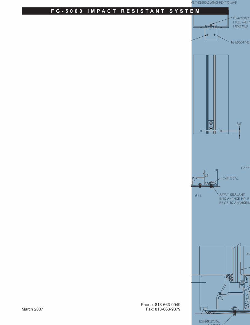
FG-5000-FP-13
FS-42 SCREWSHOLES ARE FACTORYFABRICATED.
MATCH DRILL HOLESIN ENDS OF THRESHOLD
AND ATTACH USINGFS-42 SCREWS
ALTERNATE THRESHOLD ATTACHMENT TO JAMB
1. Door frame and threshold shall be completely assembled with joints neatly aligned and tight.2. Door frame shall be installed square and plumb. Measure frame diagonally from corner to corner and shim until the measurements are equal.3. Level door frame threshold at the high point in the slab. It is preferable to not have a high point in the slab. The door frame is designed to have the jambs run down to the slab.4. Install fasteners through frame and threshold anchor holes and securely anchor to the substrate. Position shims between framing and substrate to prevent members from bowing.5. Install door stops.6. You are now ready to install the door.
3/8"
March 2007 33
F G - 5 0 0 0 I M P A C T R E S I S T A N T S Y S T E M
INSTALLATION OF DOOR FRAME

FP-5000-PP1 setting side block, FS-114 (#8 x 3/8" PPHSMS) fasteners for attachingD-152 glass stop and FG-1133 gasket are shipped loose.1. D-152 glass stop may be installed on either interior or exterior side of the door. It is recommended that D-152 be installed on the interior side of the doors receiving panic hardware to allow for reglazing without removing the panic bars.2. Pilot holes are predrilled in D-152 glass stop. Determine side of door you desire to place the glass stop and match drill holes into the horizontal rails, vertical door stiles and attach as shown below.
3. Install FP-5000-PP1 adhesive back setting block/side block as shown below. Blocks may be doubled as required due to glass tolerances.
D-152
FS-114
FG-5188 SPACER GASKET
LEVELING SCREW
SIDE BLOCK
GLASS SETTING BLOCK
SIDE BLOCK
March 200734
F G - 5 0 0 0 I M P A C T R E S I S T A N T S Y S T E M
DOOR PREPARATION AND GLAZING

4. Center glass in opening on setting blocks and aligned with side blocks.5. Once the glass is in the correct position, lightly screw the glass jack down to the top of the glass.6. Install horizontal S-83 glass stop first.
Note: Top stops are notched to clear glass jack. Be sure to hook the stop into thedovetails on the rails and stiles; then snap into place. A mallet may be used todrive stops into place.
7. Install vertical S-83 glass stops.8. Roll FG-1133 gasket into S-83.9. Mask off glass with 2" wide low adhesion masking tape and install Dow 795 or 995 into the cavity between the glass and D-152 glass stop. Remove masking tape immediately after installation of silicone taking care not to damage or pull silicone from the cavity.
SILICONE
MASKING TAPE
FG-1133
S-83
March 2007 35
F G - 5 0 0 0 I M P A C T R E S I S T A N T S Y S T E M
DOOR PREPARATION AND GLAZING

Install entrance frames first. Subsill butts against door jamb(s). The subsill abutting the door jamb does not require an end dam.
NOTE: Subsill sealant is applied after frame panels have been installed and anchored (ref sill on page 13 for weeps).
NOTE: Add sealant in FG-5109 filler pocket and tool.
CW-998 LEFT OUTFOR CLARITY
FG-5166 SUBSILL
SEAL NON-STRUCTURALFASTENER
SEAL
CAULK
TH-57 THRESHOLD
FG-5168 DOOR JAMB
March 200736
F G - 5 0 0 0 I M P A C T R E S I S T A N T S Y S T E M
ENTRANCE DOOR FRAME INSTALLATION WITHSUB-SILL FOR SIDELIGHTS

March 2007 37
F G - 5 0 0 0 I M P A C T R E S I S T A N T S Y S T E M
PARTS LIST
FG-5167
FS-38
FG5000-FP-13
FS-54
FS-8
FG5000-FP-12
FG5000-FP-10
CW-998
SM-5601
FG-5105
V-2110
FG-1133
ITEM DESCRIPTION
PRE-GLAZED FRAMING (cont’d)
Sill FlashingEnd Dam
(Attach with 2 ea.FS-54 screws)
18" LongAnchor Plate
for FG-5161 Jamb
Steel AttachmentScrew
Threshold Clip Packfor TH-57
2 per bag with(8) FS-42 Screws
#14 x 1" HHSTSAssembly Screw
Bulb Gasket
Joint Sealant Tape1/8" x 1/2"
Setting Block2 per lite
5/16" Tape SSAInterior Spacer
ExteriorGlazingGasket
Flat Fillerfor FG-5121
#10-24 x 3/8"UCPFH Screws
FG-5110
Head
FG-5109
FG-5161
FG-5166
FG-5121
FG-5155
Heavy WallMullion
FG-5165
FG-5115
FG-5112
FG-5114
FG-5111
FG-5113
ITEM
Subsill Flashing
Mullion
Wall Jamb
Filler Plateat Sill
Glass Stopfor Sill
Sill
Pocket Filler forFG-5121 & FG-5155
Glass Stop forIntermediate Horizontal
IntermediateHorizontal
Filler Plateat Head
DESCRIPTION
PRE-GLAZED FRAMING

FG-5193
Vertical Mullion
FS-38
FS-8
FG-5180
FG-5200
FG-2122
Flat Filler Plate
HP-17
FG5000-PP-9
FG5000-FP-6
FG5000-PP-8
Left HandWater Diverter
DESCRIPTIONITEM
Steel Reinforcing10'-0"
Use with FG-5121
FG-5196
FG-5190
FG-5191
FG-5189
FG-5195
FG-5201
ITEM
FG5000-FP-5
Right HandWater Diverter
Subsill Flashing
Corner Mullion(Fits with FG-5196)
#14 x 1" HHSTS Assembly Screw
Setting Blockfor Door Header
2 per lite
Pocket Filler forFG-5193 & FG-5195
Glass Stop
Head/Sill
Steel AttachmentScrew
Steel Reinforcing10'-0"
Use with Wall Jamb
Intermediate Horizontal
Heavy Mullion
Wall Jamb
DESCRIPTION
PRE-GLAZED FRAMING (cont’d) SSG AND DRY GLAZE FRAMING
March 200738
F G - 5 0 0 0 I M P A C T R E S I S T A N T S Y S T E M
PARTS LIST

FG-5199
Setting Block
FG-5192
9955
FG5000-FP-10
FS-54
FG5000-FP-5
Water Diverter
FG-2188
FG-5185
FG-1133
5946
5947
SM-5601
ITEM
Sill Flashing End Dam
(Attach with 2 ea.FS-54 screws)
#10-24 x 3/8"UCPFH Screws
Steel Reinforcing10'-0"
Flat PVC Filler(Runs betweenanchor plates)
Interior SpacerGasket
(SSG option)
Exterior GlazingGasket
(SSG option)
Setting Chair
Interior Glazing Gasket
(Dry glaze option)
Exterior GlazingGasket
(Dry glaze option)
Joint Sealant Tape1/8" x 1/2"
DESCRIPTION
WET AND DRY GLAZE FRAMING (cont'd)
March 2007 39
F G - 5 0 0 0 I M P A C T R E S I S T A N T S Y S T E M
PARTS LIST
March 2007Phone: 813-663-0949
Fax: 813-663-9379
NON-STRUCTURALFASTENER
Interior
9/16"
FG-5000-FP-13
FS-42 SCREWSHOLES ARE FACTFABRICATED
MATCH DRILL HOLESIN ENDS OF THRESHOLD
IN CLIP AND ATTACHUSING FS-42 SCREWS
ALTERNATE THRESHOLD ATTACHMENT TO JAMB
3/8"
CAP SEAL
APPLY SEALANTINTO ANCHOR HOLEPRIOR TO ANCHORING
CAP SEAL
SILL
F G - 5 0 0 0 I M P A C T R E S I S T A N T S Y S T E M


![Technical specifications PLACI.pdf · 6:17 Technical specifications Plate types T2B M3/M3D TL3B/TL3P/TL3BD T5M/T5B M6, M6M, M6MD Frame type FG FG FG FG FG FD Height, H [mm] 380 480](https://img.pdfslide.us/doc/110x75/60d1fca979eea3753279e64f/technical-placipdf-617-technical-specifications-plate-types-t2b-m3m3d-tl3btl3ptl3bd.jpg)


![Jerry Goldsmith - Alien - Easy Music Notes · [FG]arp lead [FG]arp echo [FG]arp lead*merged [FG]bass [FG]bass echo [FG]bass*copied [FG]pizz [FG]pizz echo*copied [FG]pizz echo*merged](https://img.pdfslide.us/doc/110x75/5ae4246f7f8b9a90138e8a61/jerry-goldsmith-alien-easy-music-fgarp-lead-fgarp-echo-fgarp-leadmerged.jpg)


![G-GridFGRange - geo-textile.com · WebSite: E-Mail:info@geo-textile.com Item Unit Specification FG 25-25 FG 30-30 FG 40-40 FG 50-50 FG 80-80 TensileStrength [ASTMD6637] MD (kN/m)](https://img.pdfslide.us/doc/110x75/5f98fb25e64e6a12fe00f050/g-gridfgrange-geo-website-e-mailinfogeo-textilecom-item-unit-specification.jpg)