Embed Size (px)
Citation preview

Storm Drain System
• Design and Construction Standards • Storm Drain Installation Detail
Specifications No. 31
City of Petaluma - Sonoma County- California
Public Works & Utilities 202 North McDowell Boulevard
Petaluma, CA 94954
~- 4-~ __.j~~?c..--APPROVEDBY:~ ~Q
Kent R. Carothers, P.E., Operations Manager
1 of 1 November 2018
Storm Drain System Construction Standards
Standards List
Std. No. Title Date Approved
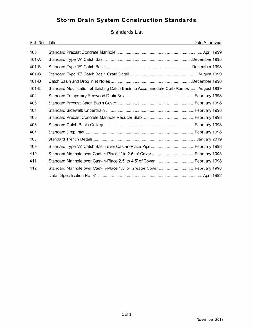
400 Standard Precast Concrete Manhole ........................................................................... April 1999
401-A Standard Type “A” Catch Basin ........................................................................... December 1998
401-B Standard Type “E” Catch Basin ........................................................................... December 1998
401-C Standard Type “E” Catch Basin Grate Detail ........................................................... August 1999
401-D Catch Basin and Drop Inlet Notes ....................................................................... December 1998
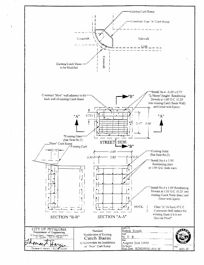
401-E Standard Modification of Existing Catch Basin to Accommodate Curb Ramps ....... August 1999
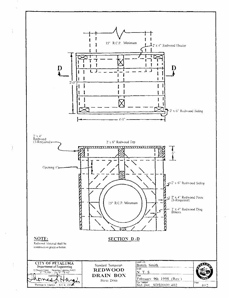
402 Standard Temporary Redwood Drain Box ............................................................. February 1998
403 Standard Precast Catch Basin Cover .................................................................... February 1998
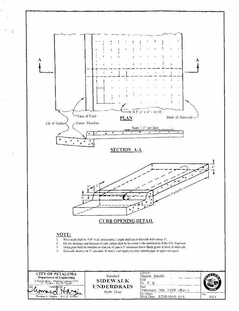
404 Standard Sidewalk Underdrain ............................................................................. February 1998
405 Standard Precast Concrete Manhole Reducer Slab ............................................. February 1998
406 Standard Catch Basin Gallery ............................................................................... February 1998
407 Standard Drop Inlet ................................................................................................ February 1998
408 Standard Trench Details .......................................................................................... January 2019
409 Standard Type “A” Catch Basin over Cast-in-Place Pipe ...................................... February 1998
410 Standard Manhole over Cast-in-Place 1’ to 2.5’ of Cover ..................................... February 1998
411 Standard Manhole over Cast-in-Place 2.5’ to 4.5’ of Cover .................................. February 1998
412 Standard Manhole over Cast-in-Place 4.5’ or Greater Cover ................................ February 1998
Detail Specification No. 31 ........................................................................................... April 1992
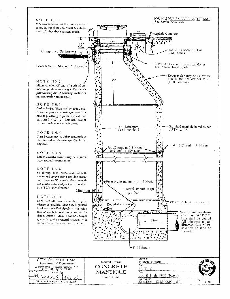
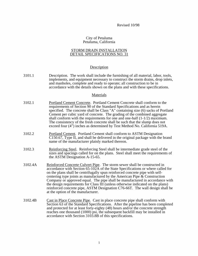
N 0 T E N 0. I FOR 'vfAN110l.E COVER .-\ND FRAME (Sec St:\\er Standards 1
When manholes are insta lkd in unimprrwl!d areas. the top of the .:ov~ 'hall be a mmimum of I foot above adjacent grade.
, .. ~
ft! ~~~~~
NOTE NO.2 :\!inimum of one 3" and 6" grade adjustment rings. \laximum height of grade adjustment ring 20". Altc:mately, contractor my cast grade rings in place.
NOTE NO.3 Gasket Seal~. "Rarn-nc:k" or equaL may be used in joints. eliminating necessity for outside plast~g of joints. Typical joint uses one 3 4"x2-l 2" "Rarn-nek" seal or two seals in high wat~ table areas.
N 0 T E N 0. 4 Cone Sec1.ion may be either .:oncentric or eccentric unless oth~wisc 'pec-iiied by the Engineer.
NOTE N 0. 5 Larger diameter barrels rna' be required under special .:ircumstan.:.:s.
N 0 T E N 0. 6 Set all rings in 1:3 mortar bed. W ~t both tongue and groove before applying mortar andseningring. Wipeinsideofjointssmooth and plaster outside of joint with one-half inch ( 1 2") layer of mortar.
Minimum
NOTE NO.7 Construct all flow channds of pipe whereever possible. Aft~ base is poured break out top hal' of pipe flush with inside face of manhole Wall and .:onstruct t"shaped channel. \lake elevation chang.es gradually and directional chang.es with smooth curves. Set ring base in mortar.
CITY OF PETALUMA Department of Engineering
2~ Bassen Stre~r . Petalwna CJi.if0rrua C ... SOS2 -:-o- -s -!30-l · Fax_ -o- --g ~3-
" .. *<I
il;
, ......
' ,
I 36"
7 •
Bar
Reducer slab rna\ be: use where pipe is too shallow for taper. (H20 Loading)
-l8" Minimum -----1 -- See Note: No. 5
Standard manhole barrd as per AST.:v! crs
Standard Precast
CONCRETE MANHOLE
Storrn Drain
Plaster l 2" \\ ith l.3 Mortar.
Plaster 6 .. tlllet. I 3 mortar.
i\Lmmum
L>ra'j\n Bv
Butch Smith
N. T S Date
A ril 14th 1999 (Rev )
~ ~
P>f: 400
ftle Sumber Std. Det. SDSOOOO .400
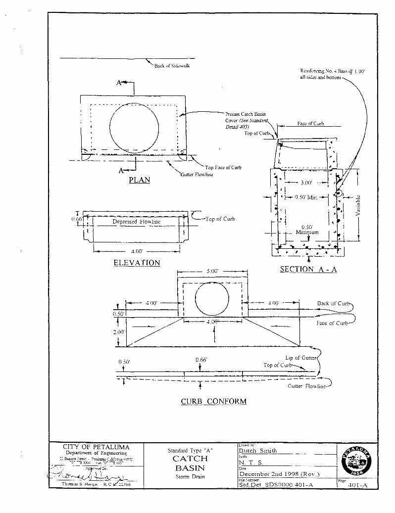
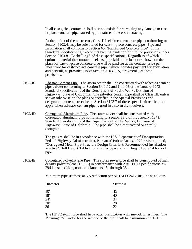
Back uf Sid.:walk R~infon.'Ulg :--io . .; Bars'~ 1.00' all si<ks and bonom
-----Precast Catch Basin
Cover (See St:md.Jrd~ Det:lil 40JJ "
Top ofC~~========7-·~·
Face of Curb
r----------:::::::::::::~:;~ LTop of Curb Depressed FIO\_~·I_in_e __ +-l-r--
----l -1.00'
ELEVATION r---- 5.00' SECTION A- A
0.66' 0.50'
t 1 i I ___ c __ ~ . 1.------_lc ________ .__T______ Gutter Flowline
CITY OF PETALUMA Department of Engineering
:: Ba.s.s.:n Street - P:ta.iuma C.ilifcuua_ Y~952 .- "•T > "30-l · F:cx "0" > .l-1}
CURB CONFORM
Standard Typ<: "A"
CATCH BASIN Storm Drain
L'r.l~na}-
Butch Smith Scale
N T. S Date
December 2nd 1998 (Re\'.) File ~umt>a"" Std.Det. SDS0000.401-A
Page 401-A
I o
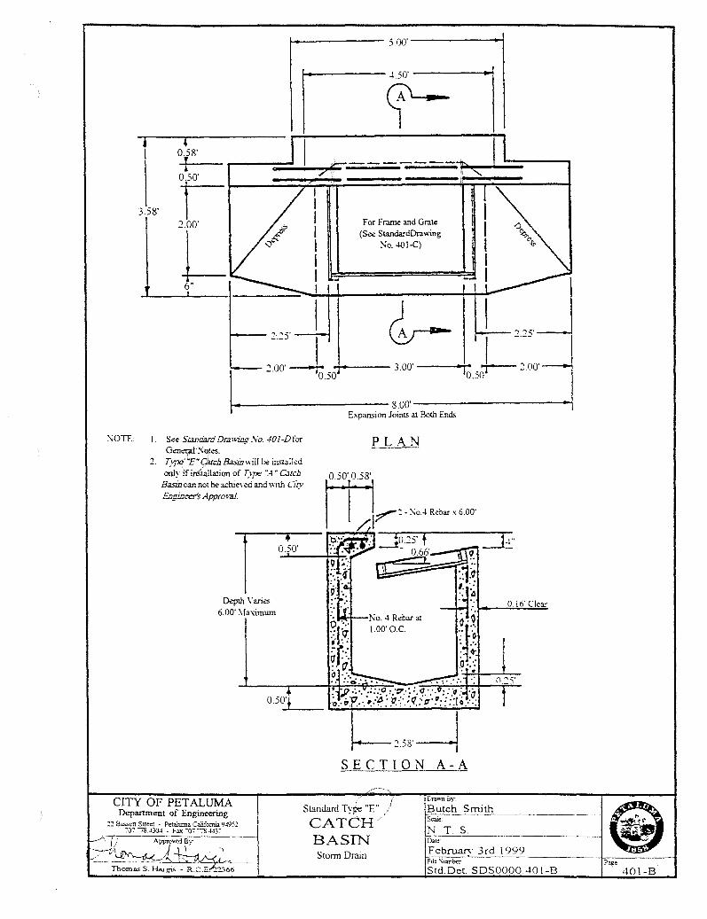
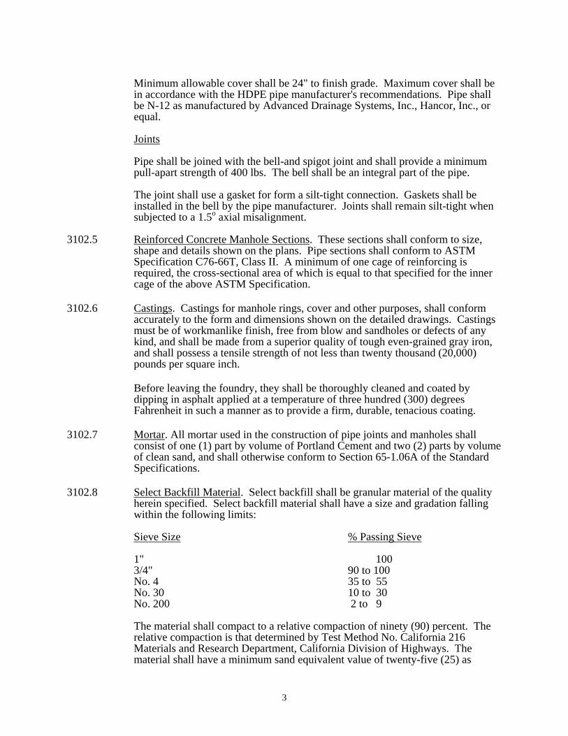
458' i r---:=::...!.......,..:c---;; ------- -:)::1 .... 1 ~-.L.::=;----, ~a l 7-· t'
3.58' I 2.00'
L 6"
For Frame and Grate (See StandardDra..,.ing
:-<o. 401-C)
:.:s· l .., 00'- ..;-.--- 3 00' ___ ..,...
I -- •o.so
t---· ---------- 8.00' __________ __,
C\OTE: I. See S=d:JrdDr.:n+ing.Vo. 401-Dfor G<!n.:r;t!;<.'ot~.
2. l)pc,.tE" CfUch &sum ill b.: installed
only ifinSiallation of T_vpe ~4 "C.uch Basin can not b.: achie\'cd and ..,.;th Ciry Ecginer:r's Approval
D.!pth Varies
6.00' ~laxi.mum
Expansion Joints at Both Ends
PLAN
t----258~ SECTION A-A
CITY OF PETALUMA Department of Engineering
.2:2 Bassett Street · Pt:taluma Cahforrua 9495:' ~07 ~ J3().< • Fax "07-:& M}:
Standard TyJ?e "E"
CATCH BASIN
Butch Smith S<:ai:
N T. S.
0.]6' Clear
Storm Drain Februarv 3rd 1999 · 1 Approved By
-~111\.~ •. )~ . ..., , '-V'~'>. •. A,.--- FUe \umber
Thomas S. H..rgis - R.C.E. -2366 Std.Det. SDSOOOO 401-B Page
401-B
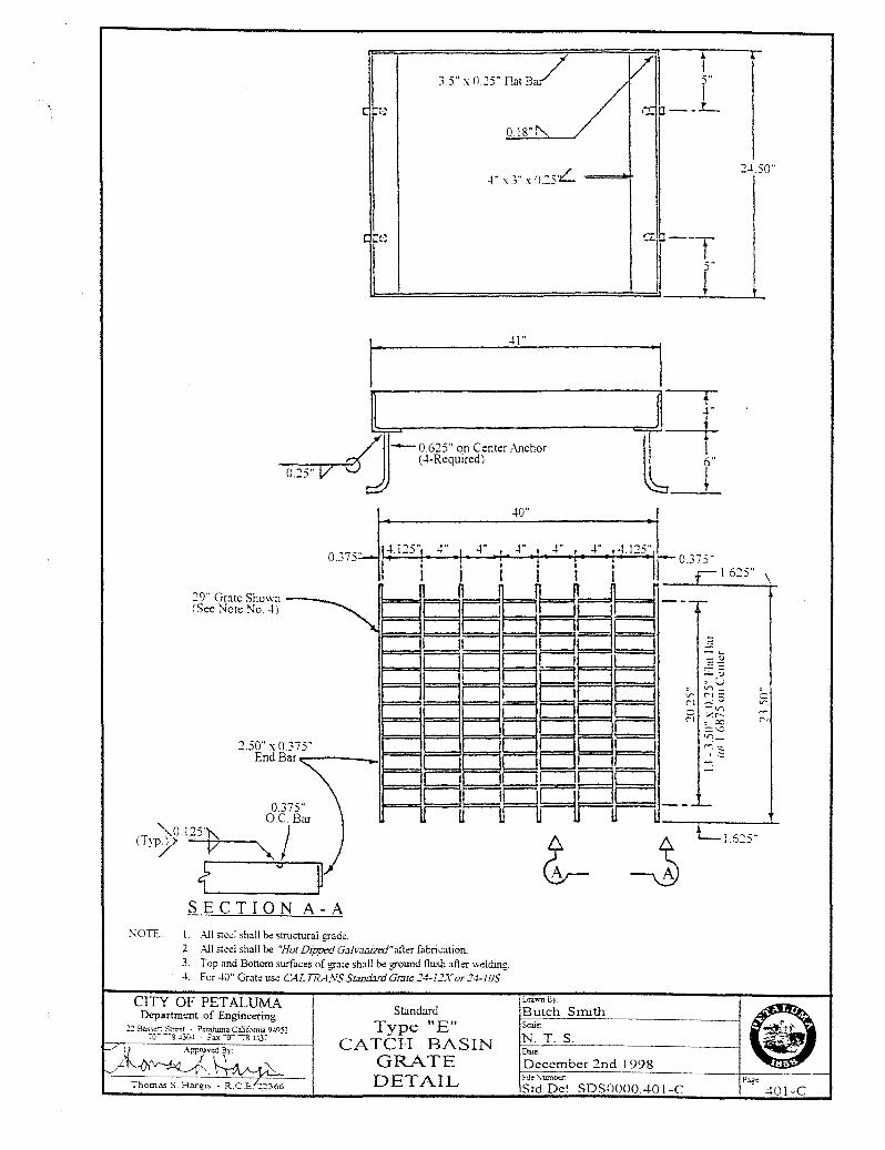
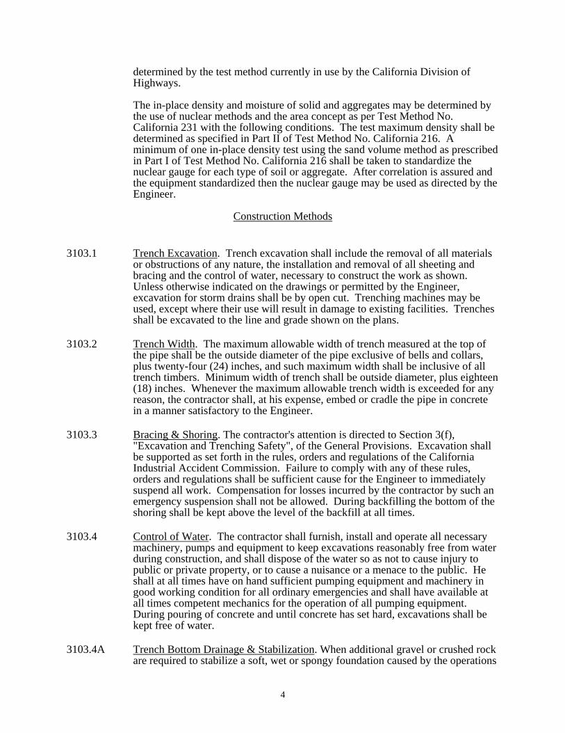
l 35">0SAmB7 /v~ l <:!: IJ - - ..!_
0 18"~
-i" - , .. - o ~,·L X-> X --
r: ~ •• .1..,,;.,
41"
40"
SECTION A-A
:--;orr: I. All st~ei shall be structural grade. 2. All st~l shall be "Hot Dipped Gaft.-:wized"afl..er fabrication. 3- Top and Bon om surfaces of grate shall be ground flush after welding. 4. For 40" Grate use CALTRA:VS S=d:mi Grate 14-l:!X or :!4-JOS
CITY OF PETALUMA Department of Engineering
:2 Bassen S~t · P:raiuma Ca!iforrna 94951 ~o- ----s "30-1 - Fa.x -o7 -:a ~r
Standard LrrawnBy-:
Butch Smith
N. T. S. D=
a: '~--~ t 5"
t
~,
---r-
6"
~
- ~
:::!
- , -. --V"\
V'\ <'I <'I --V'\
r:t :.<r--X ::::--=
~_:
""· s ' r-,
Type "E" CATCH BASIN
GRATE DETAIL
December 2nd 1998 Fue Sumba:
Std.Det SDS0000401-C
2-1.5 0"
\
-V'_ ~-C'l
--101-C
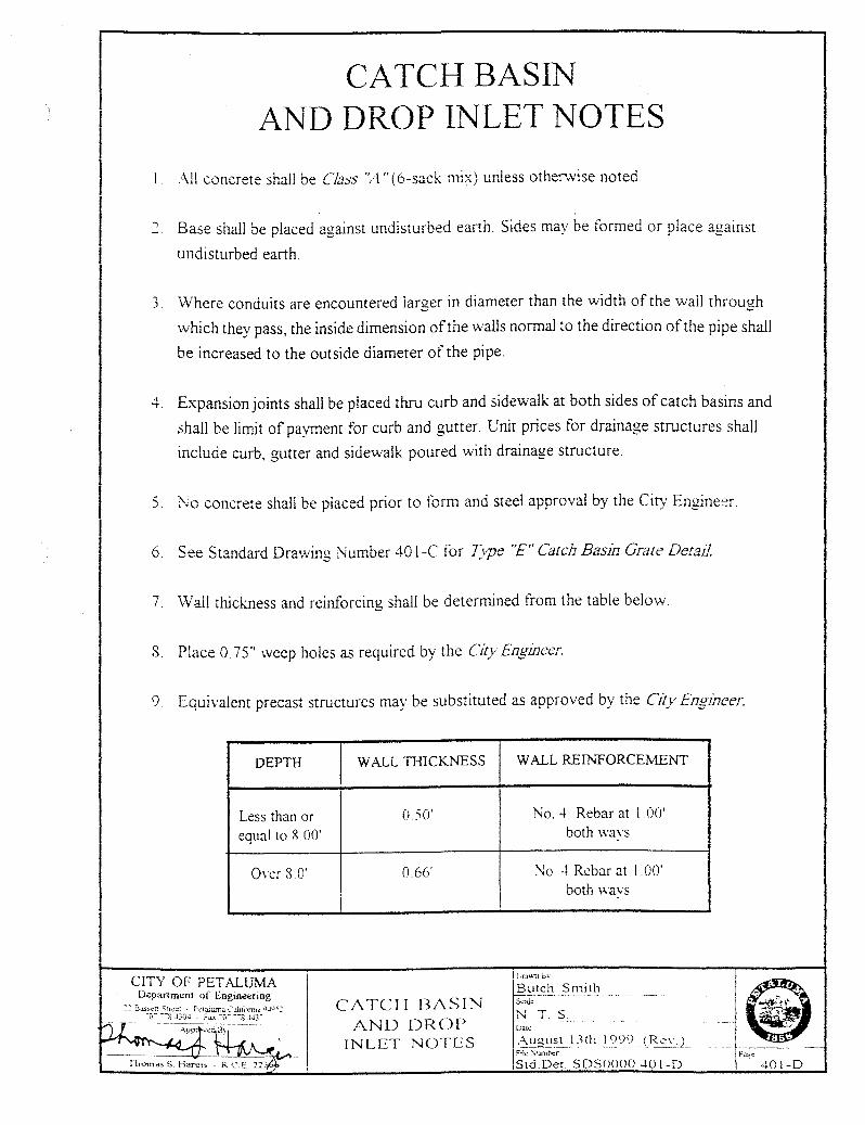
CATCH BASIN AND DROP INLET NOTES
:\ll concrete shall be Class "A" ( 6-sack mix) unless otherwise noted
Base shall be placed against undisturbed earth. Sides may be formed or place against
undisturbed earth.
3 'Where conduits are encountered larger in diameter than the width of the wail through
which they pass, the inside dimension of the walls normal to the direction of the pipe shall
be increased to the outside diameter of the pipe.
4. Expansion joints shall be placed thru curb and sidewalk at both sides of catch basins and
shall be limit of payment for curb and gutter. Unit prices for drainage structures shall
include curb, gutter and sidewalk poured with drainage structure.
) No concrete shall be placed prior to form and steel approval by the City Engine~r.
6. See Standard Drawing Number 401-C for l}pe ''£"Catch Basin Grate Detail.
7 Wall thickness and reinforcing shall be determined from the table below.
8 Place 0. 75" weep holes as required bv the Citv En!!incer. J o/ ~
9 Equivalent precast structures may be substituted as approved by the City Engineer.
DEPTH
Less than or equal to 8. 00'
0\Cf 8.0'
CITY OF PETALUMA D.apartment of Engill£€ring
:: B.L..,:.;;-r: Strc::: P.:tliu..'T1a Ca.Ufl'rT'J.J 4Jo":
~~J\ ThOtnd!!. S. Haro,;~<:: - R.C .£. 21?(f
WALL THICKNESS
0 50'
0.66'
CJ\ TCH RJ\SIN AND DROP
INLET NOTES
WALL REINFORCEMENT
No. 4 Rebar at l 00' both \\'3\'S
~o 4 Rebar at 100' both wavs
IL'r.l\.1.11 b-.
~utcl_'! Smitb ScaJ::
N. T. S
-2~1,_1s_t_ I 3th~ I 999 _j__~..?\ )
I Ftl!! \iumr>o:r - ~
Std Det SDSOOOO -W 1-D Page
401-D
-----
!I I !! l rr!l ==:£
\
Existing Curb Ramp
~Construct Tvpe "A" Curb Ramp
-~O:':'~ ~~ ~ ~ ~ ~ ~ ~ ~~::k~ ~ ~ o
' ...,_ ' )/ ~--------------/I Q I
_/ I ~ I Existin~< Catch Ba.sm I ~ I - ~
to be Moditied I r.' I
stall No.4- 0.50' x 0.75'
Construct "Nev11" \\/all adjacent to the~ I :· "~" "L-Shape"(Angle) Reinforcmg back wall of existmg Catch Basm Dowels at 1.00' 0 C. (0.25'
into extstmg Catch Basm Wall) . r- .- .....-- -..... _ and Grout With Epoxy
t I r <I d 1 ,~J _ J
o;;:j( .. ·I 'T • I . I j r I "A" ~·~·_I I l' : I
l t tl I ' > : ~<I~ 2.
1
!7' 300'
~r. : ~ J'
"J.J\."
J / . 1": ... I ~ .... / ~
*Existing Grat~ L:: ___ .._.__.__ ~ ---~ " " (See Note No.2) STREET' sr; New Curb Ramp
11 11
I /l0 -~)_, 11 __
1 //Ex1stmgCurb B
/ - ;<----- 4.00' ,..----Existing Grate I 1 I ~ -~./ (See Note No.2) o so·~L 2.83' ------r--iu.)v
- - _j I ) Install No.4 x 1.00' I Reinforcing Bars 1---------J 1 at 100' O.C. both ways
I 1 ,
SECTION "B-B"
CITY OF PETALUMA Department of Engineering
::;: Bassett Street · Pera.luma C.ilifom.Ja 9-N52 -u-:- -z ~'JO<l - Fa.'- ... 0710 J.-43"7
I J I ,,,
I
ll' I • I ! !
I I I
11 I '
~Install No.4 x 1.00' Reinforcing / Dowels at 100' O.C. (0.25' into
existing Catch Basin Base) and Grout with Epoxy.
NOTE:
SECTION "A-A"
Class "A" (6-Sack) P.C.C. Contractor shall replace the
existing Grate if it is not "Btcvcle Proof'
Standard Moditication of Existing
Catch Basin to Accomodate the Installation
of "Nc:w" Curb Ramp
I Drawn ev !Butch Smith Scale ~4-'@ 1-!N_:'.:_· _,Tc..:·_:::S:_. ---------------l ~ Date
August 2nd 1 999 __ · ·
!File S'umber IPag;- -1Std.Det. SDSOOOOAO!-E . 401-E
D L_
--+--+: -v---t-+ I 15" R.CP Minimum
I
:z· x -r· Redwood Header
D I _J. I
2'-Q"i----------'-_.l.---------t I I
I 1 I I l
l ~=====-==_===0=====~~
:·x.r Red\\OOd (3-Requtred'
NOTE: Redwood \!akrial shall b,:
construction grade or bener.
CITY OF PETALUMA Department of Engineering
:z· x 6" Red\l.ood Top
-r 6"
j_
,- 2' x 4" Rt:d\\ood Posts (6-Required)
l' x 4" Redwood Dtal! Braces -
SECTION D -D
Standard Temporal'\
RED\-VOOD DRAIN BOX
Stom1 Drain
Ln~n B~-
Butch Smith @ E<T s ·~-February 9th l 998 .i.R~c::.-\_' :...) ---t::--------1 ru::: \umber Pag:: Std.Det. SDSOOOO 402 402
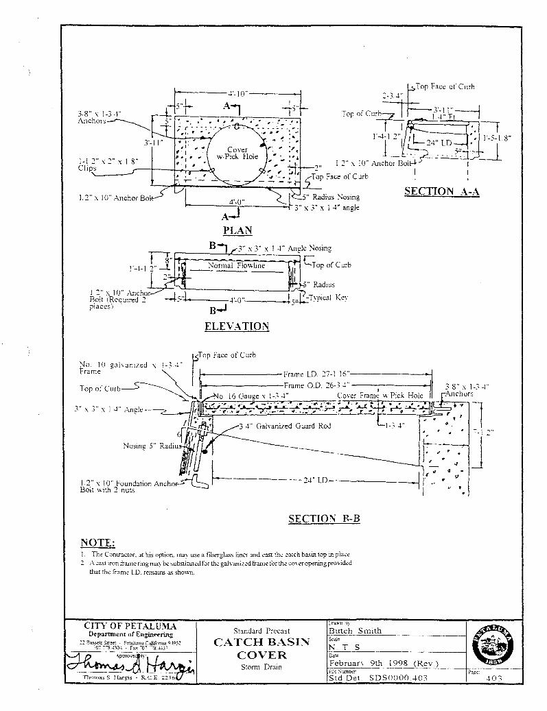
r-------.r-1 0"------<i
-Ts .. ~
1-1 2" X 2" X I 8" Cli!JS '------
L2" x 10" .A-nchor Bo
3" :..: 3" :..: I 4" .Angle
NOTE:
, 1*- . . ". --·--·-~· : ~ ...
. "
SECTION A-A 4'-0"
AJ PLAN
t----------Frame l.D 27-1 16'"----------1
Frame 0 D 26-3 4" •j o 16 Gauge x 1-3 4" Co\er Fram~ \\ P1ck Hole
SECTION B-B
1. The Contractor. :~this option. mav usc a fiberglass liner and ~ast the ~atch basin top in place. 2 . .-'I. cast iron frame ring may be substituted forthe gah·anized frame lor the co,eropaling provided
that the fr:une LD. remains as sh0\\11.
CITY OF PETALUMA Department of Engineering
:2 Bassett Stt~t - P!taluma Cahforrua Q.1951 ?Q" "ll "30~ . Fax ·o; ""8-l-130
Standard Precast
CATCH BASI~ COVER
Storm Drain
GT.i9>11 By
Butch Smith &4je
N T. S Date
FebruarY 9th 1998 (Rev ) Ftl~ Sumbcr
Std Det SDS0000.403 403
A
L ' ~----~-~---------~--' . J .:.. _:_ _:_ - L ~---- _:_
I
I
~\v~-;;.·~~~·
A
_j
PLAN Back of Side\\all.:--
Lip of Gutter
Gutter F'-to-~~1-in_e ____________ -===~==~~========~==~~~--, ,... Siooe I J" ocr foot
0
SECTION A-A
ClTRB OPENING DETAIL
NOTE: !. Wire m.:sh shall b.: ·f-0" wid~ (minimum). L~ngth shall <:qual si~walk with minus 4". 2. On site dr.1inage and location of ~urb outlets shall be by a\\ner to the satisfaction of the Citv Engineer. 3. Drain pip.: shall be installed so that top of pip.: is 3" minimum b.:low finish grade at back of sidewalk. 4. Sidewalk drain to b.: 3" ~heduk 40 heavv v.all rigid poly·;invl.:hloride pip.: or approved equal.
CITY OF PETALUMA Department of Engineering
: .. :;a;~,TI by
Butch S mi~.::t~h ________ ----J Scai~:
Standard :::! Ba."-Sett Str;:er · Petaiuma C.:ili.fonua ~41l'i2
'OC -'ll ~30" • Fa., ~07.''7'8.M37 SIDEWALK U~DERDR~IN
Storm Drain
~ FebruarY 9th 1998 (Rev ) " Fue >:umber • ---. ----"~:_:__:__ __ -+pc-,.,-<-----t
N T. S
Std.Det. SDSOOOO 404 404
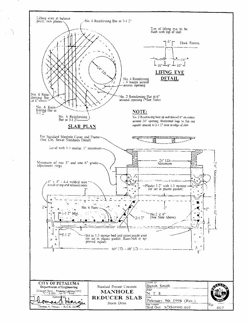
Lrfunu t:\eS :11 babnce pomt.-t\\'o places 6 Rem1orcmg Bar :1t 3-l ::;-
No. 6 Rein forcing Bar at 3-1 :- \
No. 6 Reinforcing) Bar at 3-l :2'-' ---
SL;\B PL\.N
For Standard Manhole Cover and Frame (See City Se\\er Standards Detail)
Mrnrmum of one 3" and one 6" grade adjustment nngs
CITY OF PETALUMA
T OJ) oi liriing eve to bt: !lush wah top of slab
1 6 .. r Hook Recess -----
Jl~~· L !O"J_8 .. 110" J LIFING EYE
No. 4 Reiniorcim:r - 4 hoops around access opernng
No. ::; Reinforcimz Bar at 6" around opening ("See Note)
NOTE:
DETAIL
No.: R~rnforcing b.:nr up and spac~d 6" on c~nt~r around 2-1" opening. Horizontal l~gs to fan out equallv spaced. to 2-1 :·-:lear at cdg~ of slab.
~l!tltt11~flVIA
L;rdv.n B:-
Department of Engineering Standard Precast Concrete Butch Smith
l\L\.NHOLE REDUCER SLAB
Storm Drain
Seai<
N. T S Date
FebruarY 9th 1998 (Rev ) Fuc Swnbcc
Std.Det. SDSOOOO 405 Page
405
.. :.:.:::-::::::::: · ..
welded wire
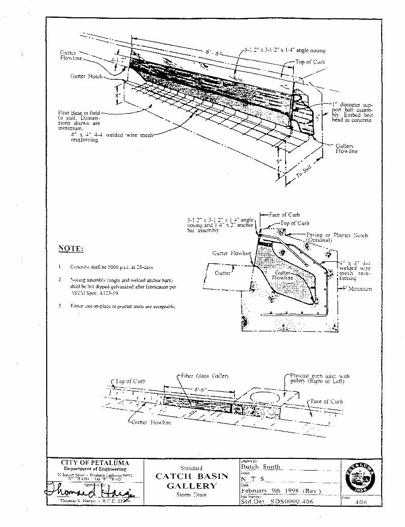
NOTE:
I. ConcT~Ie shall be 3000 p.s.i. at ::8-days.
~- :\osmg assembly (angle and welded anchor bars)
shall be hot dipj><!d galvanized after fabrication per .-\ST:\l Spec . .-\123-59
3 Eithc'!' cast-in-place or precast units are acceptable.
CITY OF PETALUMA. Department of Engineering
/3-12"x3-1.2"x !A"anglenosing
3-l 2" x 3-l 2" x 1 -1" amde nosinl! and I -1" x 2 ·· ancfior bar assemblY
Ura""'n ~Y
Standard Butch Smith
Top of Curb
~
2~ Ba..<;sett Stret:l - Petaluma Cahforrua 0-tO)~ ~o~ ""78 J30J • !'ax ·o~.-"8 .wr CATCH BASI~
GALLERY
Scale
N. T. S. Dale
February 9th 1998 (Rev ) Storm Drain Ftle\iumk
Std.Det. SDS0000.-106
-· I" diameter sup.. port bolt assemblv. Embed bolt head in concrete.
Galler. Flowli'ne
406
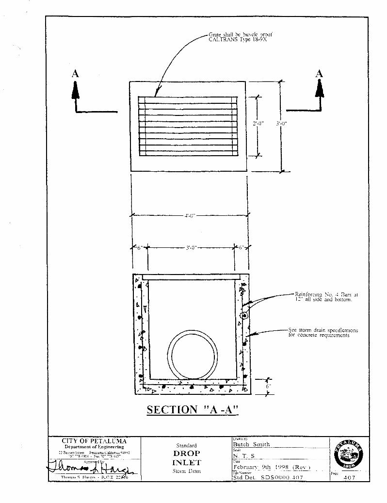
A
L l
Grate shall be bic\cle proof CALTRA.:."lS T\-pe 18-9X
1 :2'-0"
J 3'-0"
~------- -f-0" ---------.(
CITY OF PET~..LUl\'L\ Depanment of Engineering
:~ E'...a.."-"-<!fT Strt:::! · Petaiuma C.ilifcnuJ. 0-1952 ·o~ --g ~30" . F"' ·o--, ~r
---· R.:inforcmu No. -l Bars :Jt 12" all side and bottom.
----~ee storm drain specific:Jtions lor concrete requtrements
SECTION "A -i\"
Standard
DROP INLET Storm Drain
Butch Smtth
NT S Cate
Februa~ 9th 1998 (Rev ) ru~ Sum::-er.
Std.Det. SDSOOOO 407 -+07
PLEASE REFER TO CITY STANDARDS 219.1 - 219.3
STANDARD TRENCH
DETAILS
DATE: JAN 7, 2019 I SCALE: N.T.S.
APPROVED BY;
~~-Kent R. Carothers, P .E. Operations Manager C60671
DRAWN BY: TKM I NO. 408
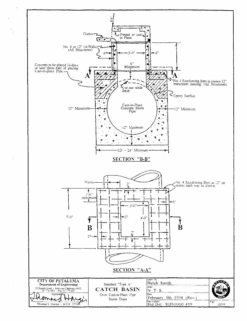
Gutter
No.4 at 1:2" (4-Walb)·~~· --(All Structures)
7'-0"
CITY OF PETALUi\L\ DeparnnentofEngmeering
22 B..l.Ssctt Strect - Pt:taJwna Caltforma \)J952 70- "7'""8 -l30J - Fax -o-:- -:-":ii .!..1:;-
4 .
v . .,
Cast-in-Place Concrete Stonn
Pipe
. 1
-q·
\ 1-~~t------I.D - 24"" Minimum----'~.-!~
SECTIO~ "B-B"
I I
Yanes-- --1•-----
1'-6" mmtmu
t
SECTION "A-A"
Butch Smith Standard "T~pe A"
CATCH BASI::"i Scale
N T. S
No.4 Reinforcin11. Bars as shown 1:2" ma'Qmum spacing. (All Structures)
Surface
:--io 4 Remforctm: Bars :.tt I.:" on center each W3\ as shO\\ n
Over Cast-in-Place Pipe Stonn Dram February 9th 1998 (Re:.l__
409 Flie Sumber
Std.Det SDSOOOO 409 P:ig:
Epoxy
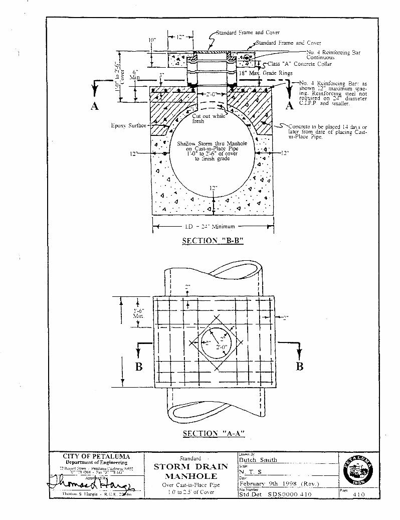
Shallow Stann thru Manhole on Cast-in-Place Pipe 1 '..{)" to 2'-6" of cover
to timsh grade
.· q· .... 4·
~ <I .. <l
-..5"-c one rete to be placed 1-1 da\ s or later from date of placin~r Cast-m-Place Pipe. -
~ I.D - :-1" Minimum -----to~--1 SECTION "B-B"
IT .
j
CITY OF PETALUl\U. Department ofEngineerinl!
2~ Bassen Street · Petaiwna Cahfcrrua V..to~~ co· ·7~ j}Q4 . Fax "07 ""'S·.w;·
r B +--+--t-
-+--+-
SECTION "A-A"
Standard
STORl\1 DRAIN IVV\.~HOLE
Over Cast-in-Place Pipe 1.0' to :.5' of CoYer
lJra•;,rn By
Butch Smith
NT S Dale
February 9th 1998 (Rev ) Ftle Sumba
Std.Det. SDS0000.-1 I 0 410
Epo:-.:y
f + 1'-6" :V1aXJmum
CITY OF PETALUMA Department of Engineering
:!~ Bass.t::n: Street - Pet:a.luma Cahfonua (IJ(l52 -o- -g -G0-1 - Fax -o- -s ..W3-:"
10"
f'A:)If-1t---:r-----No. 4 Rt:mforcmg Bar con-tinuous. -
.<J •
~ .. ' . 4
. · 4
\I-""'4----I.D. - 24- Mimmum
SECTIO:\' "B-B"
SECTION "A-A"
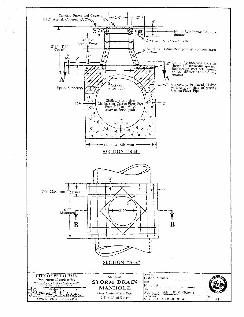
Standard
STOR:\--1 DR;\.IN lVL;\.NH 0 LE
Over Cast-in-Place Pipe 2.5' to 4.6' of Cover
concrete taper
<1 .
Butch Smtth Scai-.<-------------------1
N T S Dat::
~ebruar• 9th__l998 (Rev ) !-'tie Sumber
Std.Det SDSOOOO 411 411
CITY OF PETALLTJ\.-L\ Department of En,.aineering
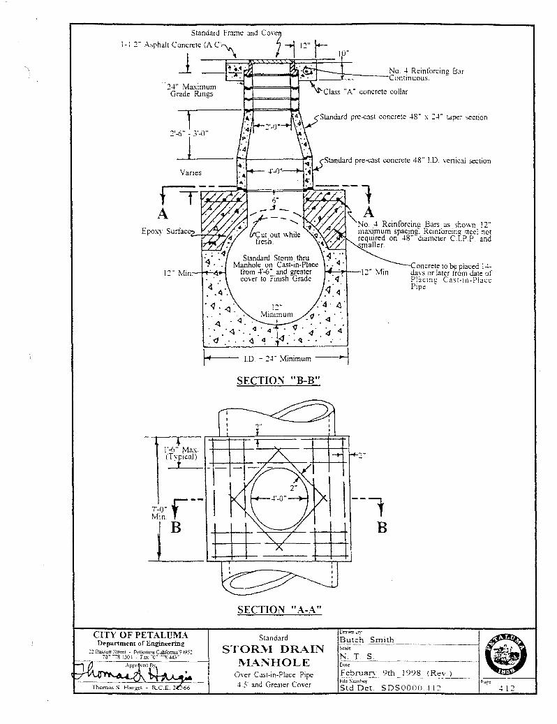
]0"
--=:=Jt:::::----No. -1 Reinforcim! Bar
Contmuous. -
concrete collar
Standard pre-cast concrete -18" J.D. venical section
No. -1 Reinforcin11 Bars as shown 12" ma.~mum spacin11~ Reintorcin2 steel not required on -18"-diameter C .I.P.P. and maller.
Con crete to be placed i -1-daYs or later from date of Pl3cmg Cast-in-Place Pipe. -
tof LD - 2-l" :vfinimum ---~
SECTIO~ "B-B"
SECTION "A-A"
Standard
STOR:\-1 DR.\.IN 1\-L~~HOLE
Over Cast-in-Place Pipe -15 and Greater Cover
., ..
~ FebruarY 9th 192§_~~:V_:l ____ +=-"----~ Ft!e :-.umber ?age.
Std.Det. SDSOOOO -112
DraV.Tl rs;.r Butch Smith
Dati!
Scale
N. T. S
412
Revised 10/98
City of Petaluma Petaluma, California
STORM DRAIN INSTALLATION
DETAIL SPECIFICATIONS NO. 31
Description 3101.1 Description. The work shall include the furnishing of all material, labor, tools,
implements, and equipment necessary to construct the storm drains, drop inlets, and manholes, complete and ready to operate; all construction to be in accordance with the details shown on the plans and with these specifications.
Materials 3102.1 Portland Cement Concrete. Portland Cement Concrete shall conform to the
requirements of Section 90 of the Standard Specifications and as herein specified. The concrete shall be Class "A" containing size (6) sacks of Portland Cement per cubic yard of concrete. The grading of the combined aggregate shall conform with the requirements for one and one-half (1-1/2) maximum. The consistency of the fresh concrete shall be such that the slump does not exceed four (4") inches as determined by Test Method No. California 519A.
3102.2 Portland Cement. Portland Cement shall conform to ASTM Designation
C150.67, Type II, and shall be delivered in the original package with the brand name of the manufacturer plainly marked thereon.
3102.3 Reinforcing Steel. Reinforcing Steel shall be intermediate grade steel of the
sizes and spacings called for on the plans. Steel shall meet the requirements of the ASTM Designation A-15-65.
3102.4A Reinforced Concrete Culvert Pipe. The storm sewer shall be constructed in
accordance with Section 65-102A of the State Specifications or where called for on the plans shall be centrifugally spun reinforced concrete pipe with self-centering type joints as manufactured by the American Pipe & Construction Company or approved equal. The pipe shall be manufactured in accordance with the design requirements for Class III (unless otherwise indicated on the plans) reinforced concrete pipe, ASTM Designation C76-66T. The wall design shall be at the option of the manufacturer.
3102.4B Cast in Place Concrete Pipe. Cast in place concrete pipe shall conform with
Section 63 of the Standard Specifications. After the pipeline has been completed and protected for at least forty-eighty (48) hours and/or the concrete strength reaches one thousand (1000) psi, the subsequent backfill may be installed in accordance with Section 3103.8B of this specifications.
1
In all cases, the contractor shall be responsible for correcting any damage to cast-
in-place concrete pipe caused by premature or excessive loading. At the option of the contractor, Class III reinforced concrete pipe, conforming to
Section 3102.4, may be substituted for cast-in-place concrete pipe. Pipe and installation shall conform to Section 65, "Reinforced Concrete Pipe", of the Standard Specifications, except that backfill shall conform to the provisions under Section 3103.8, "Backfilling", of these specifications. Regardless of which optional material the contractor selects, pipe laid at the locations shown on the plans for cast-in-place concrete pipe will be paid for at the contract price per linear foot for cast-in-place concrete pipe, which includes payment for excavation and backfill, as provided under Section 3103.13A, "Payment", of these provisions.
3102.4C Abestos Cement Pipe. The storm sewer shall be constructed with asbestos cement
pipe culvert conforming to Section 64-1.02 and 64-1.03 of the January 1973 Standard Specifications of the Department of Public Works Division of Highways, State of California. The asbestos cement pipe shall be Class III, unless shown otherwise on the plans or specified in the Special Provisions and designated in the contract item. Section 3103.7 of these specifications shall not apply when asbestos cement pipe is used in a storm drain culvert.
3102.4D Corrugated Aluminum Pipe. The storm sewer shall be constructed with
corrugated aluminum pipe conforming to Section 66-2 of the January, 1973, Standard Specifications of the Department of Public Works, Division of Highways, State of California. The pipe shall be either riveted or spirally corrugated.
The gauges shall be in accordance with the U.S. Department of Transportation,
Federal Highway Administration, Bureau of Public Roads, 1970 revision, titled, "Corrugated Metal Pipe-Structure Design Criteria & Recommended Installation Practice". Fill Height Table 8 for circular pipe and Fill Height Table 14 for arch pipe.
3102.4E Corrugated Polyethylene Pipe. The storm sewer pipe shall be constructed of high
density polyethylene (HDPE) in conformance with AASHTO Specifications M-294 latest addition, nominal diameters 15" through 36".
Minimum pipe stiffness at 5% deflection per ASTM D-2412 shall be as follows: Diameter Stiffness
15" 42
18" 40 24" 34 30" 28 36 22
The HDPE storm pipe shall have outer corrugation with smooth inner liner. The Mannings "n" factor for the interior of the pipe shall be a minimum of 0.012.
2
Minimum allowable cover shall be 24" to finish grade. Maximum cover shall be
in accordance with the HDPE pipe manufacturer's recommendations. Pipe shall be N-12 as manufactured by Advanced Drainage Systems, Inc., Hancor, Inc., or equal.
Joints Pipe shall be joined with the bell-and spigot joint and shall provide a minimum
pull-apart strength of 400 lbs. The bell shall be an integral part of the pipe. The joint shall use a gasket for form a silt-tight connection. Gaskets shall be
installed in the bell by the pipe manufacturer. Joints shall remain silt-tight when subjected to a 1.5o axial misalignment.
3102.5 Reinforced Concrete Manhole Sections. These sections shall conform to size,
shape and details shown on the plans. Pipe sections shall conform to ASTM Specification C76-66T, Class II. A minimum of one cage of reinforcing is required, the cross-sectional area of which is equal to that specified for the inner cage of the above ASTM Specification.
3102.6 Castings. Castings for manhole rings, cover and other purposes, shall conform
accurately to the form and dimensions shown on the detailed drawings. Castings must be of workmanlike finish, free from blow and sandholes or defects of any kind, and shall be made from a superior quality of tough even-grained gray iron, and shall possess a tensile strength of not less than twenty thousand (20,000) pounds per square inch.
Before leaving the foundry, they shall be thoroughly cleaned and coated by
dipping in asphalt applied at a temperature of three hundred (300) degrees Fahrenheit in such a manner as to provide a firm, durable, tenacious coating.
3102.7 Mortar. All mortar used in the construction of pipe joints and manholes shall
consist of one (1) part by volume of Portland Cement and two (2) parts by volume of clean sand, and shall otherwise conform to Section 65-1.06A of the Standard Specifications.
3102.8 Select Backfill Material. Select backfill shall be granular material of the quality
herein specified. Select backfill material shall have a size and gradation falling within the following limits:
Sieve Size % Passing Sieve 1" 100 3/4" 90 to 100 No. 4 35 to 55 No. 30 10 to 30 No. 200 2 to 9 The material shall compact to a relative compaction of ninety (90) percent. The
relative compaction is that determined by Test Method No. California 216 Materials and Research Department, California Division of Highways. The material shall have a minimum sand equivalent value of twenty-five (25) as
3
determined by the test method currently in use by the California Division of Highways.
The in-place density and moisture of solid and aggregates may be determined by
the use of nuclear methods and the area concept as per Test Method No. California 231 with the following conditions. The test maximum density shall be determined as specified in Part II of Test Method No. California 216. A minimum of one in-place density test using the sand volume method as prescribed in Part I of Test Method No. California 216 shall be taken to standardize the nuclear gauge for each type of soil or aggregate. After correlation is assured and the equipment standardized then the nuclear gauge may be used as directed by the Engineer.
Construction Methods
3103.1 Trench Excavation. Trench excavation shall include the removal of all materials
or obstructions of any nature, the installation and removal of all sheeting and bracing and the control of water, necessary to construct the work as shown. Unless otherwise indicated on the drawings or permitted by the Engineer, excavation for storm drains shall be by open cut. Trenching machines may be used, except where their use will result in damage to existing facilities. Trenches shall be excavated to the line and grade shown on the plans.
3103.2 Trench Width. The maximum allowable width of trench measured at the top of
the pipe shall be the outside diameter of the pipe exclusive of bells and collars, plus twenty-four (24) inches, and such maximum width shall be inclusive of all trench timbers. Minimum width of trench shall be outside diameter, plus eighteen (18) inches. Whenever the maximum allowable trench width is exceeded for any reason, the contractor shall, at his expense, embed or cradle the pipe in concrete in a manner satisfactory to the Engineer.
3103.3 Bracing & Shoring. The contractor's attention is directed to Section 3(f),
"Excavation and Trenching Safety", of the General Provisions. Excavation shall be supported as set forth in the rules, orders and regulations of the California Industrial Accident Commission. Failure to comply with any of these rules, orders and regulations shall be sufficient cause for the Engineer to immediately suspend all work. Compensation for losses incurred by the contractor by such an emergency suspension shall not be allowed. During backfilling the bottom of the shoring shall be kept above the level of the backfill at all times.
3103.4 Control of Water. The contractor shall furnish, install and operate all necessary
machinery, pumps and equipment to keep excavations reasonably free from water during construction, and shall dispose of the water so as not to cause injury to public or private property, or to cause a nuisance or a menace to the public. He shall at all times have on hand sufficient pumping equipment and machinery in good working condition for all ordinary emergencies and shall have available at all times competent mechanics for the operation of all pumping equipment. During pouring of concrete and until concrete has set hard, excavations shall be kept free of water.
3103.4A Trench Bottom Drainage & Stabilization. When additional gravel or crushed rock
are required to stabilize a soft, wet or spongy foundation caused by the operations
4
of the contractor, such gravel or crushed rock shall be furnished at the contractor's expense.
The Engineer shall be the sole judge of the suitability of the trench bottom and as
to the amount of gravel required to stabilize a soft foundation. The contractor shall remove any soft material and replace it with gravel or crushed rock when ordered to do so by the Engineer.
Gravel or crushed rock shall have a size and gradation falling within the
following limits: Sieve Size % Passing Sieve 2" 100 1 1/2" 90 to 100 3/4" 5 to 30 3/8" 5 to 20 No. 200 0 to 4 Payment for trench bottom drainage and stabilization shall be made at the contract
unit price bid per ton of gravel or crushed rock in place, complete including excavation and disposal of soft material and dewatering the trench.
3103.5 Disposal of Excess Excavated Material. Arrangements for disposing of excess
excavated material shall be made by the contractor. Excavated material suitable for backfilling shall be stored temporarily in such a manner as will facilitate work under the contract and not cause undue inconveniences to property owners along the sewer route.
3103.6 Pipe Laying. No pipe shall be laid until the Engineer inspects and approves the
condition of the bottom of the trench. Pipe laying shall proceed upgrade with the tongue ends of tongue and groove pipe pointing in the direction of flow. Each piece shall be laid true to line and grade and in such a manner as to form a close concentric joint with the adjointing pipe and to prevent sudden offsets in the flow line.
As the work progresses, the interior of the storm drain shall be cleared of all dirt
and debris of every description. Where clearing after laying is difficult because of small pipe size, a suitable swab or squeegee shall be kept in the pipe and pulled forward past each joint immediately after jointing has been completed. Pipe shall not be laid when the condition of the trench or the weather is unsuitable. At time when work is not in progress, open ends of pipe and fittings shall be closed.
Pipe shall be placed on prepared subgrade of imported material at least four (4)
inches deep below the barrel of the pipe. The imported material shall meet the requirements specified herein for "initial backfill" and be thoroughly compacted to obtain a final density of at least ninety (90) percent of maximum at optimum moisture as determined by Test Method No. California 216. After compaction, the bottom of the trench shall be shaped so the pipe, when laid, will have a uniform bearing under the full length of the pipe.
3103.7 Pipe Jointing. Joints in pipes eighteen (18) inches in diameter and smaller shall
be made prior to closure by buttering with mortar the joint space of the bell end of
5
the pipe section previously laid. After inserting the spigot, the excess mortar squeezed from the joint shall be removed by an inflated swab or squeegee. Joints in pipe twenty-one (21) inches in diameter and larger shall be made by partially filling the inside joint with mortar after the pipe has been laid and before the initial backfill has been placed. No mortar will be required in the outside joints of tongue and groove pipe. After the final backfill has been placed and completely compacted by jetting, joints in pipe twenty-one (21) inches in diameter and larger shall be finished by completely filling the inside joint with mortar. Before final acceptance, the joints shall be left smooth without any abrupt rise or drop in the flow line and without any cracks which will permit leakage.
The connecting bands for corrugated aluminum pipe shall conform to the
requirements of AASHO M-106. 3103.8 Backfilling. 3103.8A Initial Backfill. "Select Backfill Material" as specified in Section 3102.8 of these
specifications shall be used for initial backfill. After the pipe has been properly laid and inspected, select backfill material shall be placed on both sides and over the pipe to such a depth that after thorough compaction, the final depth shall be at least twelve (12) inches above the top of the pipe. The contractor shall be wholly responsible for damage to the pipe.
The initial backfill shall be compacted by hand tamping. The use of machine
tampers will not be permitted. The initial backfill material shall be hand tamped in layers not exceeding four (4) inches in uncompacted depth. The final depth of compacted initial backfill shall be at least twelve (12) inches above the top of the pipe.
After handtamping, the relative compaction of the initial backfill material shall be
not less than ninety (90) percent as determined by Test Method California No. 216.
3103.8B Subsequent Backfill. Above the level of the initial backfill, the trench shall be
backfilled with structural backfill (excluding pea gravel) as specified in Paragraph 19-3.06 Structure Backfill of the State of California, Department of Transportation, Standard Specifications, dated January 1988. Unless otherwise specified in the special provisions or certified by an approved soil testing laboratory that the native trench excavated material meets the requirements of structural backfill as stated above - native excavated trench material shall not be used for backfill in any portion of the trench.
The contractor shall compact by tamping and/or rolling, the backfill material in
layers not exceeding eight (8) inches in loose depth, each layer being thoroughly compacted by tamping and/or rolling before succeeding layers are placed. "Stomper" type equipment for compaction shall not be permitted. Vibrating equipment that does not damage the pipe or adjacent facilities may be used for compaction.
Subsequent backfill compacted by tamping and/or rollings shall be free from
stones or lumps exceeding three (3) inches in greatest dimension, vegetable matter, or other unsatisfactory material, and shall be compacted to a relative compaction of not less than ninety (90) percent as determined by Test Method No. California 216, except that within two and one-half (2 1/2) feet of finished
6
permanent surfacing grade the relative compaction shall not be less than ninety-five (95) percent. The contractor will be charged for the cost of all compaction tests where the test results do not meet the above specifications.
3103.8C Re-excavation. If the compaction requirements as specified above are not met,
the trench shall be re-excavated. Backfill material shall then be compacted by tamping and/or rolling as specified above until the compaction requirements are satisfied.
3103.8D Restoration of Existing Facilities. Whenever existing improvements, such as
pavements, curbs, gutters, sidewalks, driveways, storm drains, sanitary sewers, laterals, utilities, utility services, etc., have been cut or damaged in order to construct storm drains and appurtenances, the backfill shall be thoroughly compacted and all improvements restored to their original conditions. The cost of restoring all original improvements shall be included in the unit bid price for storm sewer pipe, or appurtenances, and no additional allowance shall be made therefor.
3103.9 Subgrade Preparation. The finished subgrade immediately prior to placing base
material thereon shall have a relative compaction of not less than ninety-five (95) percent, for a depth of two and one-half (2 1/2) feet below finished permanent surfacing grade, as determined by Test Method No. California 216. Mud or other soft or spongy material shall be removed and the space filled with select backfill material and rolled or tamped in layers not exceeding eight (8) inches in thickness until the above relative compaction requirement is satisfied. Subgrade preparation is not required in unimproved areas where trench surfacing is not required.
3103.10 Trench Surfacing. 3103.10A General. Where an unimproved surface is encountered the trench shall be
restored to its original surface. Where a gravel surface is encountered, it shall be replaced over the width of the
trench with Class 2 Aggregate Base six (6) inches in depth as specified in Section 26 of the Standard Specifications. Where the existing surface is some type of asphalt concrete, it shall be restored with a temporary surface followed by a permanent surface as specified herein.
3103.10B Temporary Surfacing. The temporary surfacing shall be Class 2 Aggregate Base
as specified in Section 26 of the Standard Specifications. The aggregate base shall be equal in depth to the existing pavement structural section, but in any case not less than fourteen (14) inches in depth.
The aggregate base shall be given a penetration treatment as specified in Section
36 of the Standard Specifications. Liquid asphalt used for the treatment shall be grade MC-70 or SC-70. The rate of application of the liquid asphalt shall be the maximum that will, under favorably weather conditions, be completely absorbed by the base material within twenty-four (24) hours from the time of application. A sufficient amount of liquid asphalt shall be applied to bind the aggregate base and prevent raveling. Care shall be taken that no liquid asphalt is applied to the adjoining pavement surface.
7
All temporary surfacing shall be laid within two (2) days after backfilling. Before the street is opened for traffic, all excess dirt, rock and debris shall be removed and the street surface shall be swept clean. Temporary surfacing shall be maintained constantly so that at no time will there be any mudholes nor shall the surface settle below one (1) inch nor be raised more than one (1) inch from the existing pavement. All temporary asphalt shall comply fully with the Bay Area Air Quality Management District's Regulation 8, Rule 15.
Section 302 of Rule 15 prohibits the use of "cut back" asphalt (including MC-70)
during the months of April through October in paving material or in paving and maintenance operations. The contractor shall use only slow-cure (SC) liquid asphalts for temporary trench paving during April through October.
3103.10C Permanent Surfacing. Permanent surfacing shall not be constructed until the
compaction requirements of Section 3103.8 of these specifications are satisfied. The wearing surface for permanent surfacing shall be replaced "in kind", but in no case shall the new surfacing be less than two (2) inches thick for asphalt concrete or less than six (6) inches thick for Portland Cement Concrete. A permanent surface shall be installed no later than ten (10) calender days from completion of backfill.
3103.10C1 Asphalt Concrete. The existing pavement shall be neatly cut to a depth of two (2)
inches and removed to at least five (5) inches outside each side line of the pipe trench to permit proper keying in the restored pavement. The existing pavement cut shall be straight, vertical and with no ragged edges.
The base course for permanent surfacing shall be Class 2 aggregate base as
specified in Section 26 of the Standard Specifications. The aggregate base shall be equal in depth to the existing pavement structural section, but in any case not less than twelve (12) inches in depth.
The wearing surface for permanent surfacing shall be asphalt concrete two (2)
inches minimum in depth. The asphalt concrete shall be "Type B Asphalt Concrete" with one-half (1/2) inch maximum, medium grading aggregate conforming to the requirements of Section 39 of the Standard Specifications.
3103.10C2 Portland Cement Concrete Paving. The existing pavement shall be neatly sawcut
to a minimum depth of two (2) inches and at least five (5) inches outside each side line of the pipe trench to permit proper keying in the restored pavement. The contractor shall chip along the edge of the existing concrete pavement and remove all loose pieces prior to replacing the wearing surface for permanent surfacing.
The base course for permanent surfacing shall be Class 2 aggregate base as
specified in Section 26 of the Standard Specifications. The aggregate base shall be equal in depth to the existing pavement structural section less six (6) inches, but in any case not less than six (6) inches in depth.
The wearing surface for permanent surfacing shall be Portland Cement Concrete
in conformance with Section 90 of the Standard Specifications. 3103.11 Storm Sewer Manholes. Storm manholes shall be reinforced concrete, constructed
at the locations shown on the plans and to the form and dimensions shown on the detailed plans.
8
In the construction of reinforced concrete manholes, joints shall be made in the same manner and sequence as heretofore specified for reinforced concrete pipe, tongue and groove jointed.
The storm sewer pipe shall be carried through the manhole structure and the
concrete base of the manhole shall be constructed around the pipe. The top of the pipe shall be broken out flush with the inside of the manhole wall and top of platform. Pipe stubs for main and lateral sewers shall be built into the structure as shown on the plans.
3103.12 Drop Inlets. Drop inlets shall be constructed to the lines and grades shown on the
plans and in accordance with the provisions of Sections 51 and 70 of the Standard Specifications as herein modified. Inlet boxes shall conform to "Type A Inlets" as detailed on the plans, or as otherwise specified.
The floor and the walls of the inlet box may be poured monolithically using Class
"A" Concrete. "Ordinary Surface Finish" shall be applied to all the inside surfaces of the box. No concrete shall be poured when subgrade is excessively wet. The interior of the box shall be kept free of dirt, excess mortar and other foreign materials and shall be left clean at the completion of the inlet lateral.
Backfill around the completed drop inlet shall be thoroughly tamped into place by
use of pneumatic tamper where possible, or other means approved by the Engineer. The relative compaction shall be ninety-five (95) percent.
3103.13 Payment. 3103.13A Storm Sewer Pipe. Quantities for payment shall be made by measuring
horizontally along the centerline of the storm drain less the design distance between the ends of the pipe in manholes through which the pipe does not pass. Whenever split pipe is required through a manhole, such pipe shall be included in the measurement.
The contract unit price per linear foot for reinforced concrete pipe or cast-in-place
concrete pipe shall include full compensation for all costs necessary and incidental to the complete installation of the concrete pipe storm sewer of the designated size and class, as specified herein and as designated on the plans.
3103.13B Storm Sewer Manholes. The contract unit price per each for "Storm Sewer
Manholes" of the applicable diameter, four (4) feet or five (5) feet shall include full compensation for all costs necessary and incidental to furnishing and installing a storm sewer manhole complete including excavation, backfill, ring and cover, has herein specified and detailed on the plans. The cost or setting the manhole cover to grade after the asphalt concrete pavement is placed shall not be included in the contract unit price per each for storm sewer manhole, but paid for under asphalt concrete paving.
3103.13C Drop Inlets. The contract unit price for each "Drop Inlet" in place shall include
full compensation for furnishing all labor, materials, tools, equipment and performing all work necessary to complete the drop inlet, including backfilling, and no additional allowance will be made.
9
3103.13D Cast In Place Payment. The contract unit price per linear foot measured along the centerline of the pipe shall include full compensation for the pipe in place including excavation, curing and backfill.
detail31
10