Embed Size (px)
Citation preview
Stored program concept• Stored-program concept is designed by
Hungarian mathematician John Von Neumann.• The von Neumann architecture is a design
model for a stored-program digital computer that uses a processing unit and a single separate storage structure to hold both instructions and data.
• A stored-program digital computer is one that keeps its programmed instructions, as well as its data, in read-write, random access memory(RAM).
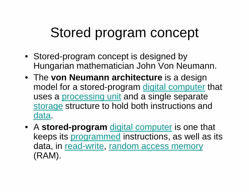
Design of the von Neumann architecture
CPU
INPUT OUTPUT
SYSTEM BUS
MAIN MEMORY
M
STOREDPROGRAMSAND DATA
Data Instruction
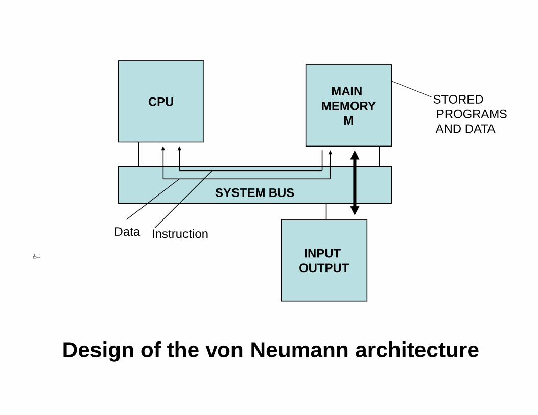
• A von Neumann Architecture computer has five parts: an arithmetic-logic unit , a control unit , a memory , some form of input/output and a system bus that provides a data path between these parts.
• Role of computer’s main memory M is to store programs and data as they are being processed by CPU.
• M is RAM• RAM permits the CPU to read or change its contents via
load or store instructions respectively.• M is backed with secondary memory that is hard disk
• You store programs and data in a slow-to-access storage medium (such as a hard disk) and work on them in a fast-access, volatile storage medium (RAM).
• The idea behind stored-program concept was to design a computer that includes an instruction set architecture and can store in memory a set of instructions (a program) that details the computation.
• A stored-program design also lets programs modify themselves while running
• An instruction set is a list of all the instructions, and all their variations, that a processor can execute.
• Instructions include:• Arithmetic such as add and subtract• Logic instructions such as and, or, and not• Data instructions such as move, input, output,
load, and store• Control flow instructions such as goto, if ...
goto, call, and return
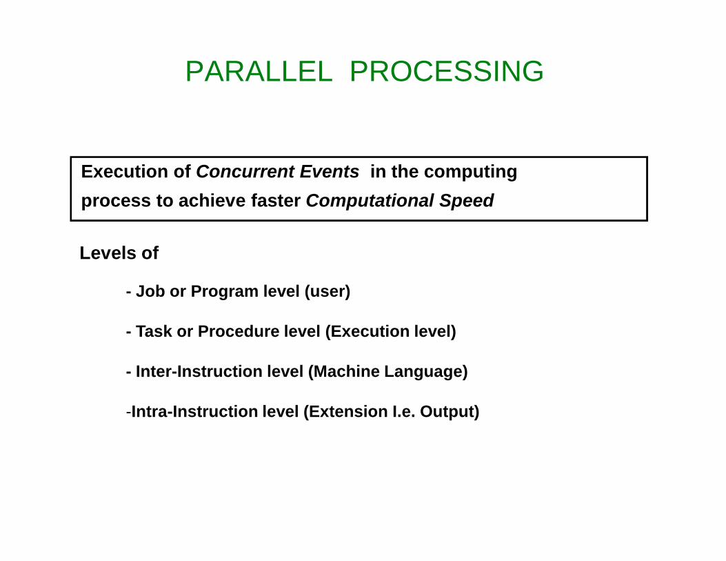
PARALLEL PROCESSING
Levels of
- Job or Program level (user)
- Task or Procedure level (Execution level)
- Inter-Instruction level (Machine Language)
-Intra-Instruction level (Extension I.e. Output)
Execution of Concurrent Events in the computing process to achieve faster Computational Speed
Flynn’s classification of computers• Michael J Flynn classified computers on the basis of
multiplicity of instruction stream and data streams in a computer system.
• It gives how sequence of instructions or data will be executed upon a single processor
• Instruction stream: is the sequence of instructions as executed by the machine
• Data Stream is a sequence of data including input, or partial or temporary result, called by the instruction Stream.
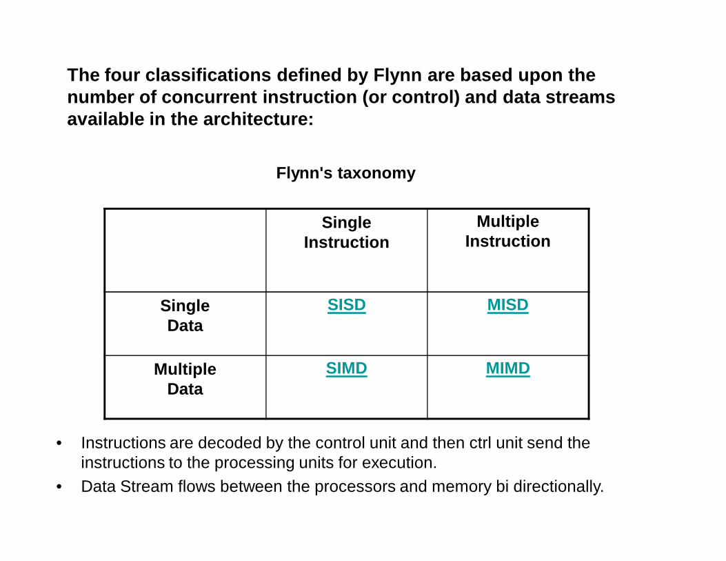
The four classifications defined by Flynn are based upon the number of concurrent instruction (or control) and data streams available in the architecture:
Flynn's taxonomy
SingleInstruction
MultipleInstruction
SingleData
SISD MISD
MultipleData
SIMD MIMD
• Instructions are decoded by the control unit and then ctrl unit send the instructions to the processing units for execution.
• Data Stream flows between the processors and memory bi directionally.
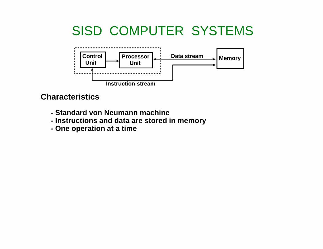
SISD COMPUTER SYSTEMS
ControlUnit
ProcessorUnit
Memory
Instruction stream
Data stream
Characteristics
- Standard von Neumann machine- Instructions and data are stored in memory- One operation at a time
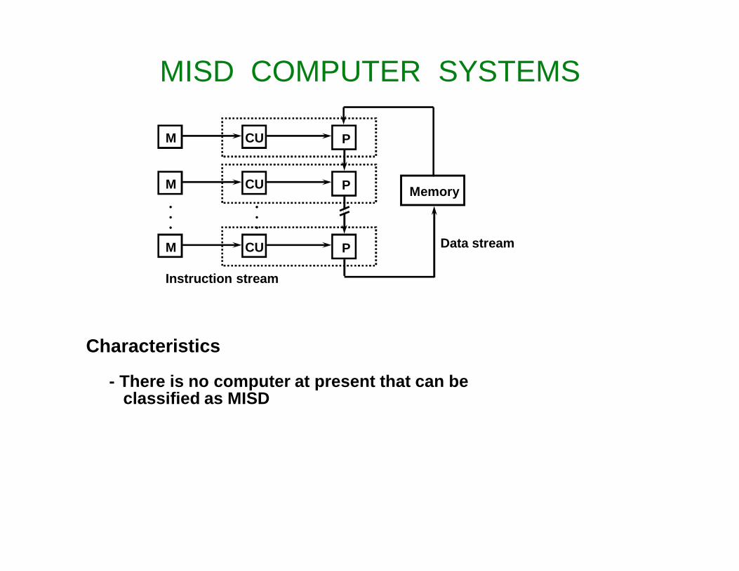
MISD COMPUTER SYSTEMS
M CU P
M CU P
M CU P
•••
•••
Memory
Instruction stream
Data stream
Characteristics
- There is no computer at present that can beclassified as MISD

SIMD COMPUTER SYSTEMS
Control Unit
Memory
Alignment network
P P P• • •
M MM • • •
Data bus
Instruction stream
Data stream
Processor units
Memory modules
Characteristics
- Only one copy of the program exists- A single controller executes one instruction at a time
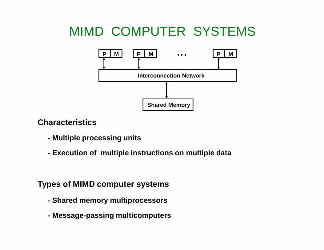
MIMD COMPUTER SYSTEMS
Interconnection Network
P M P MP M • • •
Shared Memory
Characteristics
- Multiple processing units
- Execution of multiple instructions on multiple data
Types of MIMD computer systems
- Shared memory multiprocessors
- Message-passing multicomputers
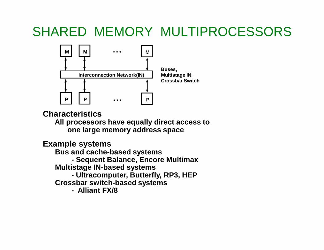
SHARED MEMORY MULTIPROCESSORS
CharacteristicsAll processors have equally direct access to
one large memory address space
Example systemsBus and cache-based systems
- Sequent Balance, Encore MultimaxMultistage IN-based systems
- Ultracomputer, Butterfly, RP3, HEPCrossbar switch-based systems
- Alliant FX/8
Interconnection Network(IN)
• • •
• • •P PP
M MM
Buses,Multistage IN,Crossbar Switch
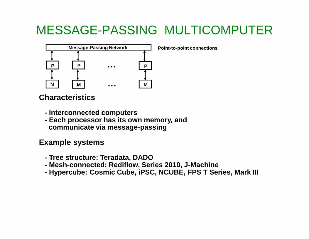
MESSAGE-PASSING MULTICOMPUTER
Characteristics
- Interconnected computers- Each processor has its own memory, and communicate via message-passing
Example systems
- Tree structure: Teradata, DADO- Mesh-connected: Rediflow, Series 2010, J-Machine- Hypercube: Cosmic Cube, iPSC, NCUBE, FPS T Series, Mark III
Message-Passing Network
• • •P PP
M M M• • •
Point-to-point connections
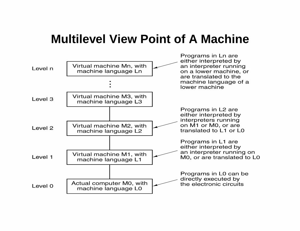
Multilevel View Point of A Machine
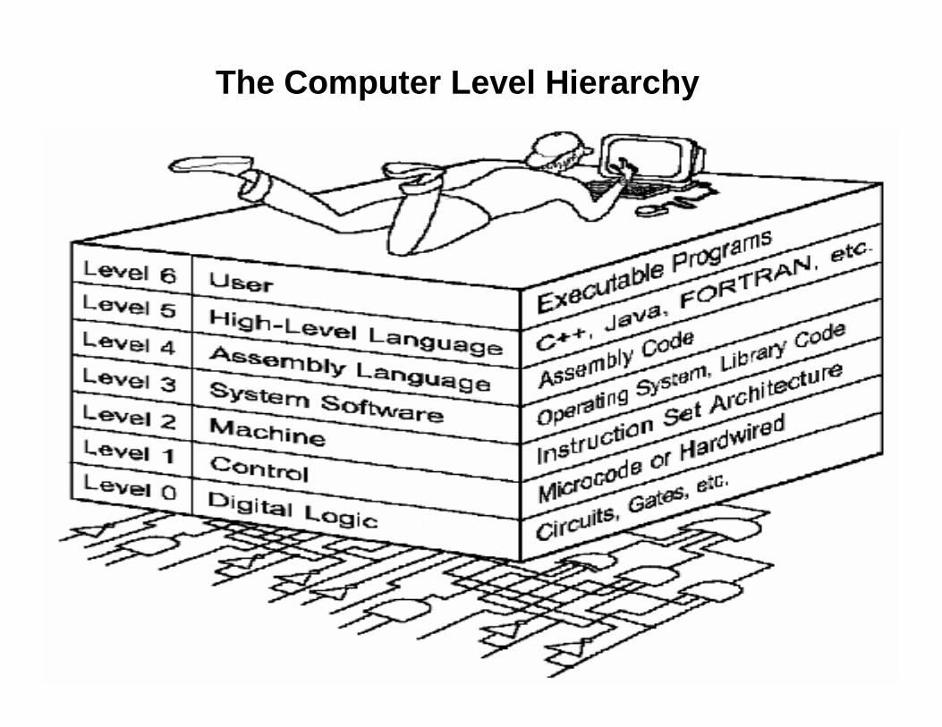
The Computer Level Hierarchy
Level 0: Digital Logic Level
– This level is where we find digital circuits (the chips).
– Digital circuits consist of gates and wires.– These components implement the
mathematical logic of all other levels.– This level is where we view physical devices
as just switches (On/Off)– Instead of viewing their physical behavior (i.e.
in terms of voltages and currents) we use two value logic i.e. 0 (off) and 1(on)
Level 1: Control Level / Microarchitecture Level
– A control unit decodes and executes instructions and moves data through the system.
– Control units can be microprogrammed or hardwired.
– Computer Architecture is the combination of microarchitecture and instruction set design.
Hardwired Control• Hardwired control units consist of hardware that
directly executes machine instructions.
• The control logic is implemented with gates, flip flops, decoders, and other digital circuits.
• It has the advantage that it can be optimized to produce a fast mode of operation
• Making any change is difficult
Microprogrammed Control
• Microprogramed control unit is built around a storage unit called control memory where all control signals are stored in program like format.
• Control memory stores a set of microprograms which are designed to implement instruction set.
• Each instruction causes a set of microprogram to be fetched.
• And its control information is extracted in a manner that resembles the fetching and execution of program from main memory.
• Design changes can be easy by just altering the contents of the control memory.
A microprogram is a program written in a low-level language that is implemented by the hardware.
Level 2: Machine Level – Also known as the Instruction Set Architecture
(ISA) Level.– Consists of instructions that are particular to
the architecture of the machine.
Instruction Set Architecture (ISA) • The Instruction Set Architecture (ISA) is the part of the
processor that is visible to the programmer or compiler writer.
• The ISA serves as the boundary between software and hardware.
• An instruction set, or instruction set architecture(ISA), is the part of the computer architecture related to programming, including the native data types, instructions, registers, addressing modes, memory architecture, interrupt and exception handling, and external I/O.
• An ISA includes a specification of the set of opcodes, the native commands implemented by a particular CPU design.
Example
• An operation (ADD) is a part of Instruction set stored in a memory. It is a binary code that tells computer to perform ADD operation.
• Control units decodes instructions from the memory. Then issues a sequence of control signals to initiate microoperations in internal computer registers
• For every operation code, the control issues a sequence of microoperations needed for the hardware implementation of the specified operation
Level 3: System Software Level
– Controls executing processes on the system.– Protects system resources.– Assembly language instructions often pass through
Level 3 without modification.– Operating System software supervises other
programs• Controls execution of multiple programs• Protects system resources. E.g. Memory and I/O devices
– Other utilities• Compilers, Interpreters, Linkers, Library etc.
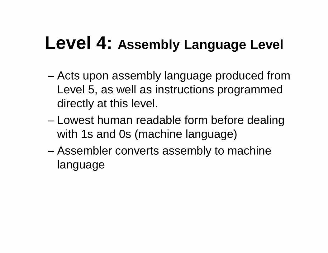
Level 4: Assembly Language Level
– Acts upon assembly language produced from Level 5, as well as instructions programmed directly at this level.
– Lowest human readable form before dealing with 1s and 0s (machine language)
– Assembler converts assembly to machine language
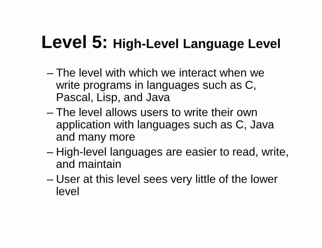
Level 5: High-Level Language Level
– The level with which we interact when we write programs in languages such as C, Pascal, Lisp, and Java
– The level allows users to write their own application with languages such as C, Java and many more
– High-level languages are easier to read, write, and maintain
– User at this level sees very little of the lower level
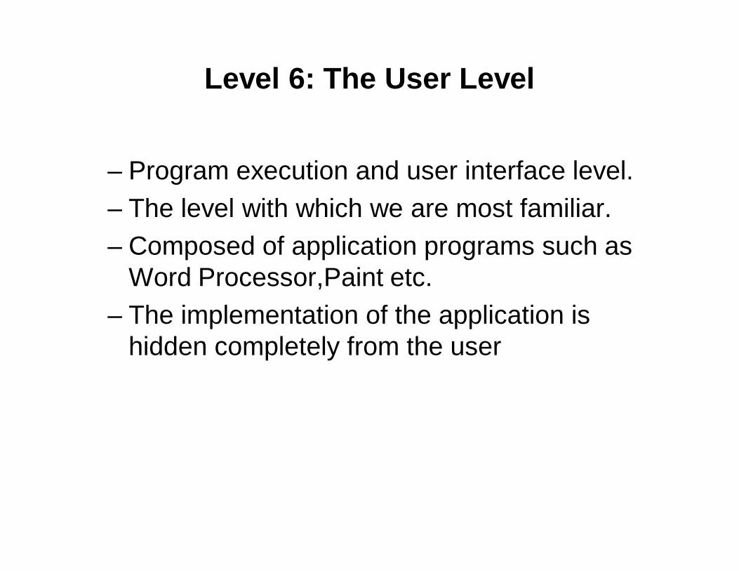
Level 6: The User Level
– Program execution and user interface level.– The level with which we are most familiar.– Composed of application programs such as
Word Processor,Paint etc.– The implementation of the application is
hidden completely from the user
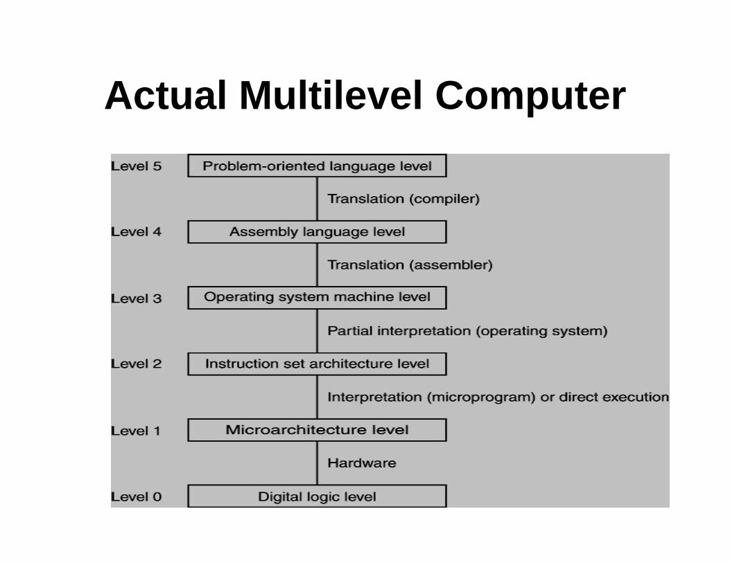
Actual Multilevel Computer
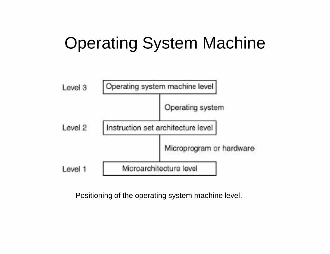
Operating System Machine
Positioning of the operating system machine level.
Introduction• An operating system is the part of the program that manages the computer
hardware.• It provides basis for application programs and acts as an intermediary
between user of a computer and computer hardware.
• OS varies in accomplishing tasks………• For example:
Mainframe OS are designed primarily to optimize utilization of hardware. P4ersonal computer operating system support complex and business
application and everything in between. Handheld computer OS are deigned to provide an environment in which a user
can easily interface with the computer to execute programs.
Thus some OS are designed to be convenient, others to be efficient, and other some combination of two.
What is an OS
• A computer can be divided into four componenets: HardwareOperating systemApplication programsUsers
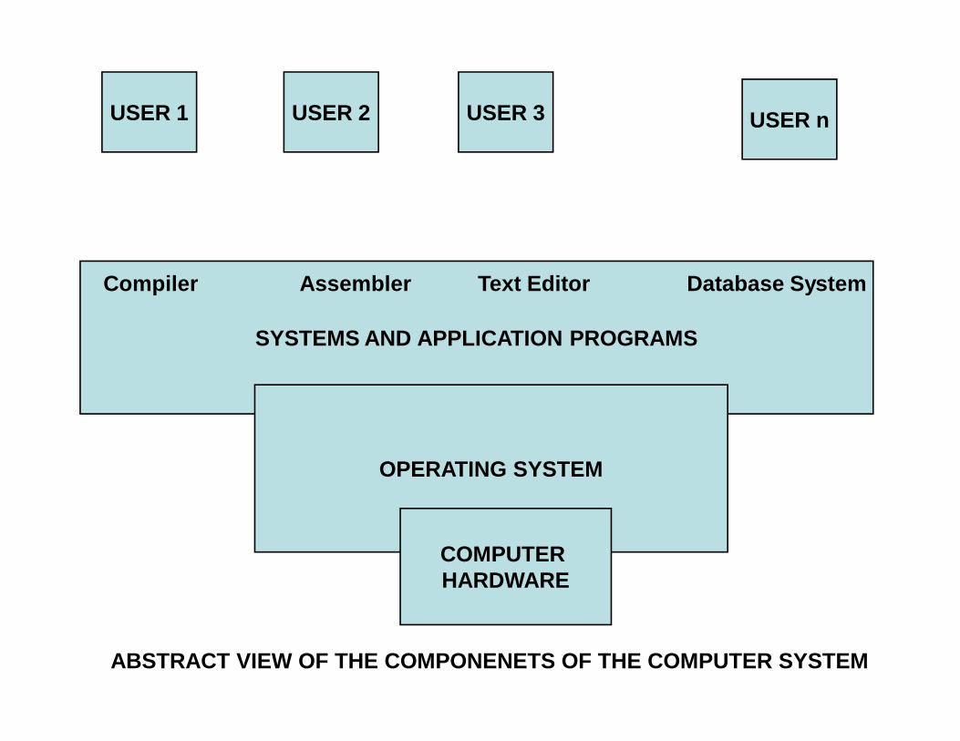
SYSTEMS AND APPLICATION PROGRAMS
OPERATING SYSTEM
COMPUTER HARDWARE
USER 1 USER 2 USER 3 USER n
Compiler Assembler Text Editor Database System
ABSTRACT VIEW OF THE COMPONENETS OF THE COMPUTER SYSTEM
• The hardware – the central processing unit, thememory, input/output - provides the basic computing resources.
• The application resources – such as word processors, spreadsheet, compilers and web browsers – define the ways in which these resources are used to solve computing problems of the users.
• The OS controls and coordinates the use of hardware among various application programs for the various users

OS can be viewed from two viewpoints :
• Users view• Systems view
Users view• User1: sits in front of PC, consisting of a
monitor, keyboard, mouse and system unit. • User2: Some users sit at a terminal connected
to a mainframe or minicomputer. Other users are accessing the same computer through other terminals.
Users view contd……..• User3: sit at workstation connected to networks of other
workstations and servers. These users have dedicated resources for their use, but they also share resources such as networking and servers – file, compute and print servers.
• User4: handheld computers – individual users – wireless .
Systems View• Os is the most intimate with the hardware• We can view it as a RESOURCE ALLOCATOR -----
• COMPUTER System has many resources – h/w and s/w – they may be required to solve a problem : CPU time, memory space, file-storage space, I/O devices and so on….
• OS acts as an manger of these resources, the OS must decide how to allocate them to specific programs and users so that it can operate the computer system efficiently.
Instruction Set Architecture (ISA)
The Instruction Set Architecture (ISA) is the part of the processor that is visible to the programmer or compiler writer. The ISA serves as the boundary between software and hardware.
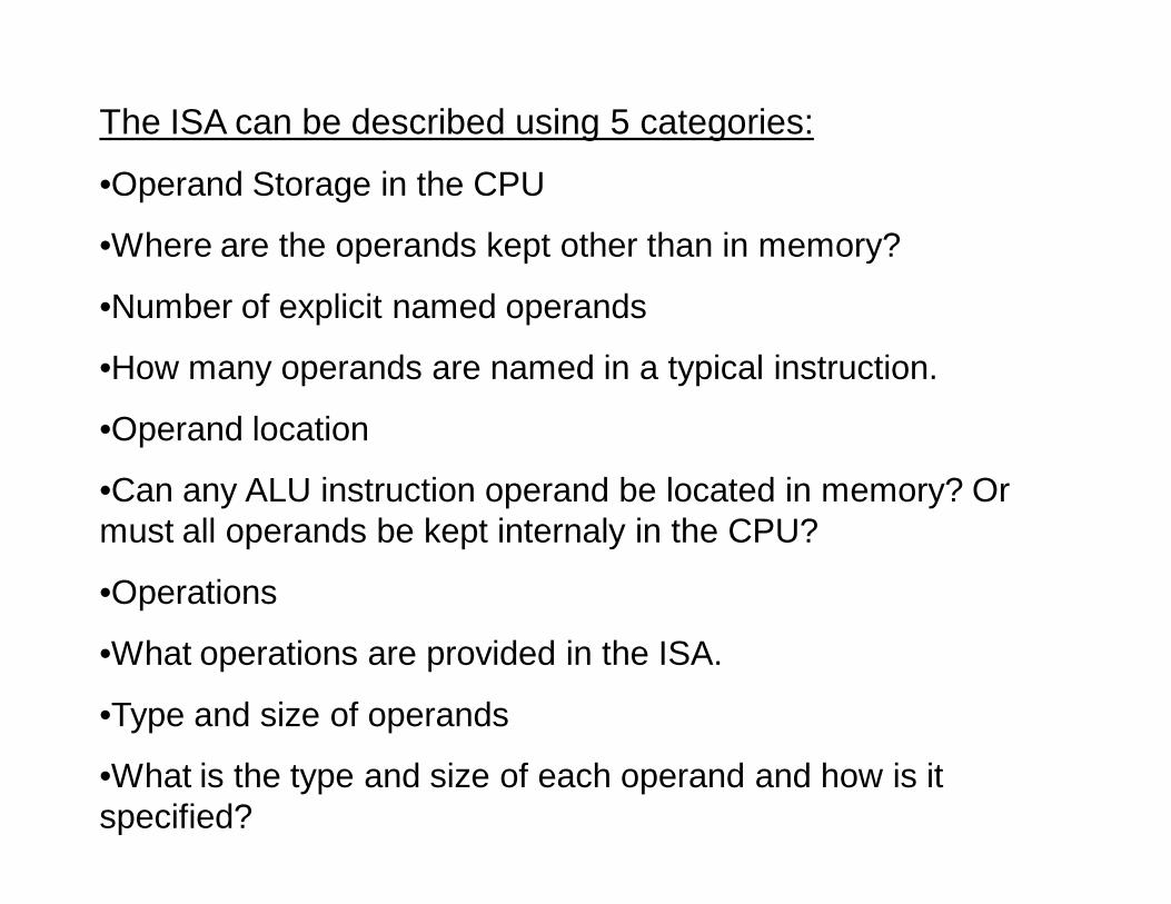
The ISA can be described using 5 categories:
•Operand Storage in the CPU
•Where are the operands kept other than in memory?
•Number of explicit named operands
•How many operands are named in a typical instruction.
•Operand location
•Can any ALU instruction operand be located in memory? Or must all operands be kept internaly in the CPU?
•Operations
•What operations are provided in the ISA.
•Type and size of operands
•What is the type and size of each operand and how is it specified?
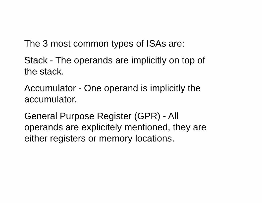
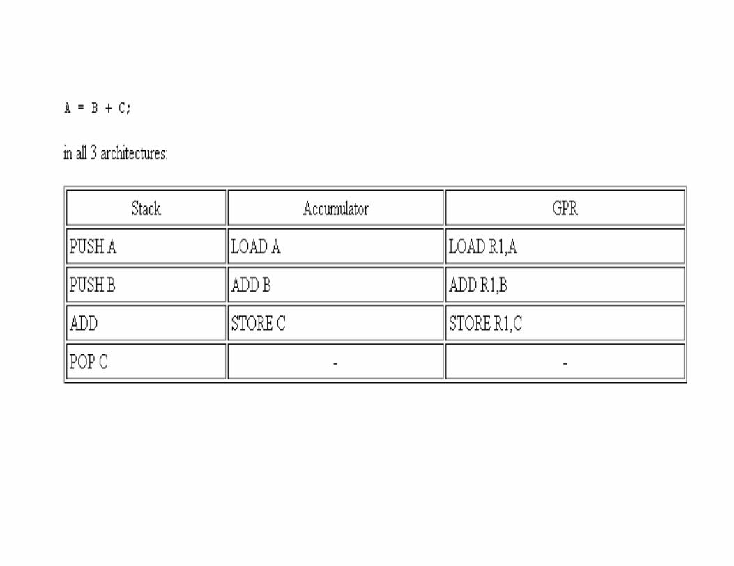
The 3 most common types of ISAs are:
Stack - The operands are implicitly on top of the stack.
Accumulator - One operand is implicitly the accumulator.
General Purpose Register (GPR) - All operands are explicitely mentioned, they are either registers or memory locations.
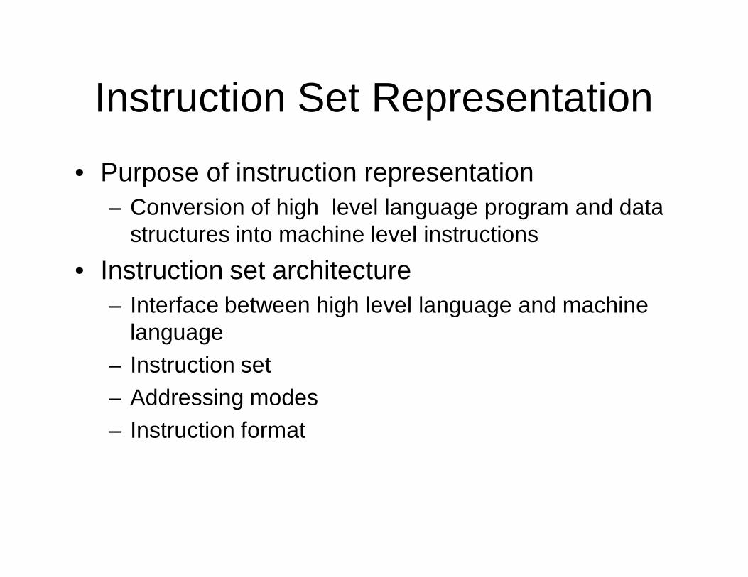
Instruction Set Representation
• Purpose of instruction representation– Conversion of high level language program and data
structures into machine level instructions• Instruction set architecture
– Interface between high level language and machine language
– Instruction set– Addressing modes– Instruction format
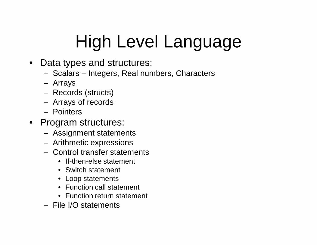
High Level Language• Data types and structures:
– Scalars – Integers, Real numbers, Characters– Arrays– Records (structs)– Arrays of records– Pointers
• Program structures:– Assignment statements– Arithmetic expressions– Control transfer statements
• If-then-else statement• Switch statement• Loop statements• Function call statement• Function return statement
– File I/O statements
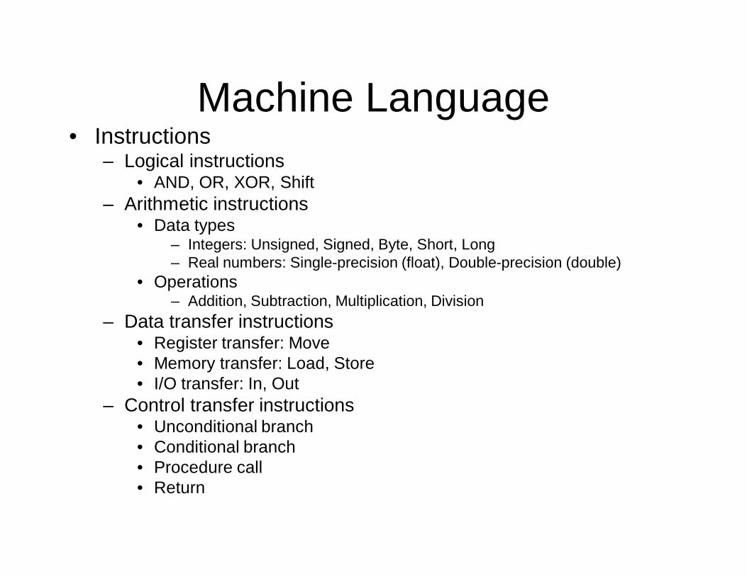
Machine Language• Instructions
– Logical instructions• AND, OR, XOR, Shift
– Arithmetic instructions• Data types
– Integers: Unsigned, Signed, Byte, Short, Long– Real numbers: Single-precision (float), Double-precision (double)
• Operations– Addition, Subtraction, Multiplication, Division
– Data transfer instructions• Register transfer: Move• Memory transfer: Load, Store• I/O transfer: In, Out
– Control transfer instructions• Unconditional branch• Conditional branch• Procedure call• Return
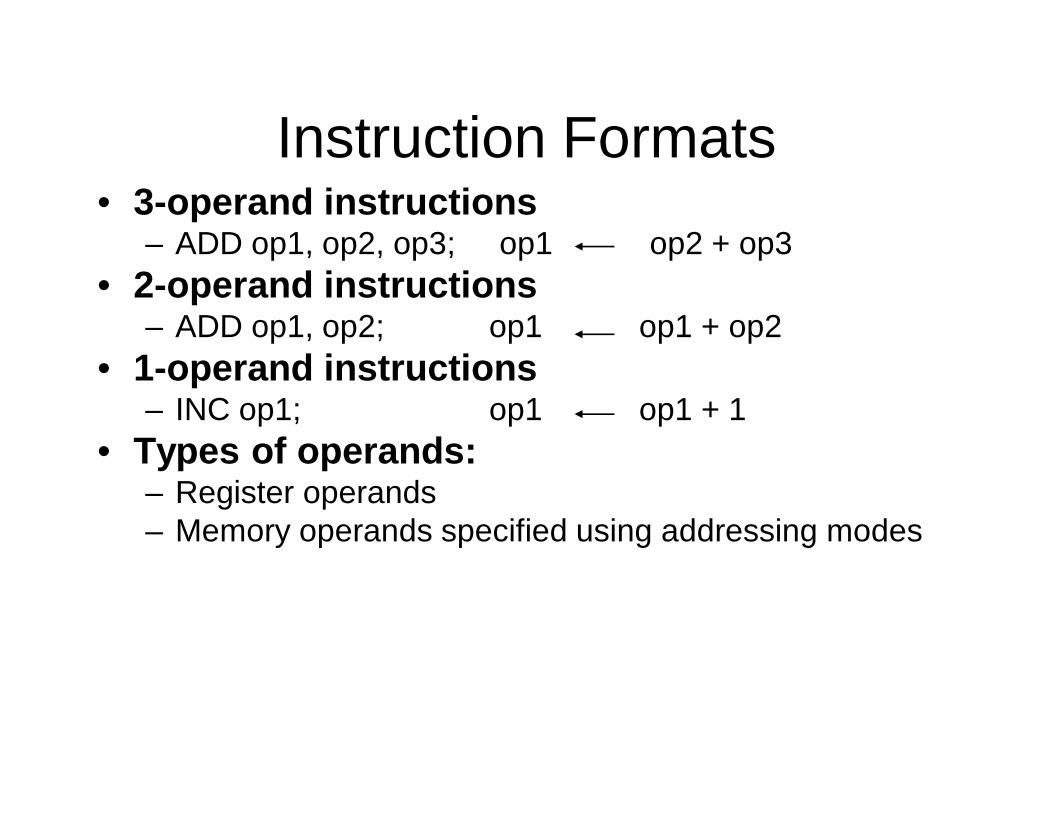
Instruction Formats • 3-operand instructions
– ADD op1, op2, op3; op1 op2 + op3• 2-operand instructions
– ADD op1, op2; op1 op1 + op2• 1-operand instructions
– INC op1; op1 op1 + 1• Types of operands:
– Register operands– Memory operands specified using addressing modes
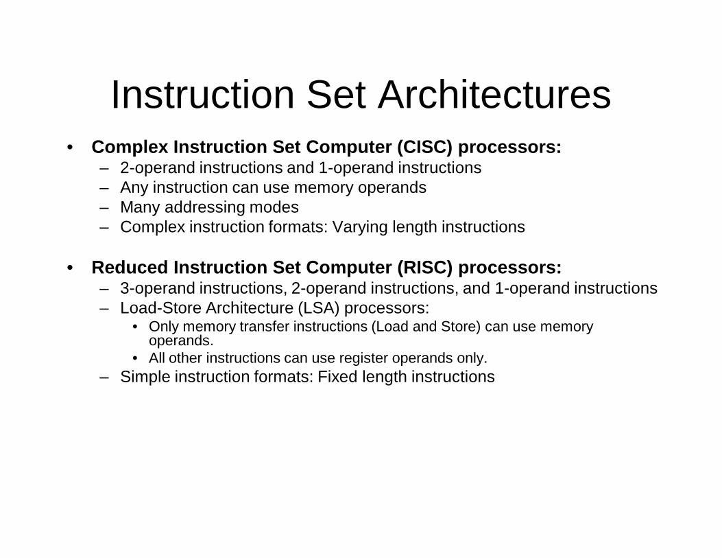
Instruction Set Architectures • Complex Instruction Set Computer (CISC) processors:
– 2-operand instructions and 1-operand instructions– Any instruction can use memory operands– Many addressing modes– Complex instruction formats: Varying length instructions
• Reduced Instruction Set Computer (RISC) processors:– 3-operand instructions, 2-operand instructions, and 1-operand instructions– Load-Store Architecture (LSA) processors:
• Only memory transfer instructions (Load and Store) can use memory operands.
• All other instructions can use register operands only.– Simple instruction formats: Fixed length instructions
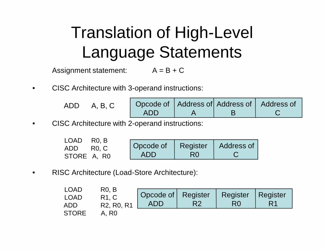
Translation of High-Level Language Statements
Assignment statement: A = B + C
• CISC Architecture with 3-operand instructions:
ADD A, B, C
• CISC Architecture with 2-operand instructions:
LOAD R0, BADD R0, CSTORE A, R0
• RISC Architecture (Load-Store Architecture):
LOAD R0, BLOAD R1, CADD R2, R0, R1STORE A, R0
Opcode of ADD
Address ofA
Address ofB
Address ofC
Opcode of ADD
RegisterR0
Opcode of ADD
RegisterR1
RegisterR0
RegisterR2
Address ofC
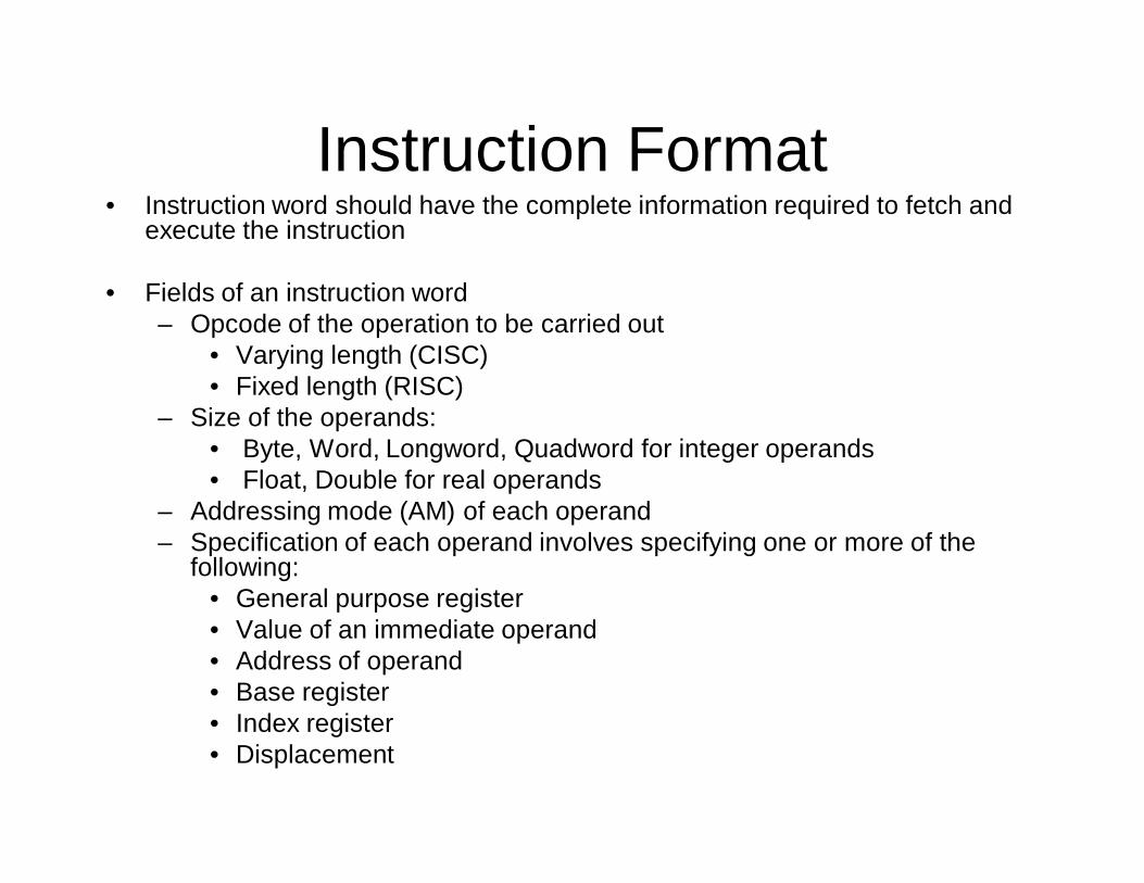
Instruction Format• Instruction word should have the complete information required to fetch and
execute the instruction
• Fields of an instruction word– Opcode of the operation to be carried out
• Varying length (CISC)• Fixed length (RISC)
– Size of the operands:• Byte, Word, Longword, Quadword for integer operands• Float, Double for real operands
– Addressing mode (AM) of each operand– Specification of each operand involves specifying one or more of the
following: • General purpose register• Value of an immediate operand• Address of operand• Base register• Index register• Displacement
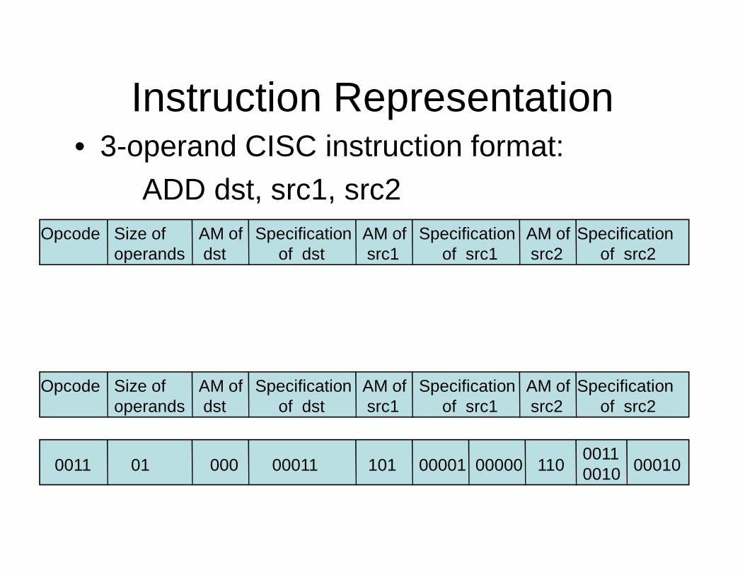
• 3-operand CISC instruction format:ADD dst, src1, src2
Instruction Representation
Specification of src2
Opcode AM ofdst
Specification of src1
Size of operands
AM ofsrc2
AM ofsrc1
Specification of dst
Specification of src2
Specification of src2
Opcode AM ofdst
Specification of src1
Size of operands
AM ofsrc2
AM ofsrc1
Specification of dst
Specification of src2
Specification of src20011 000 00010 01 11010100011 00000
00110010 00001
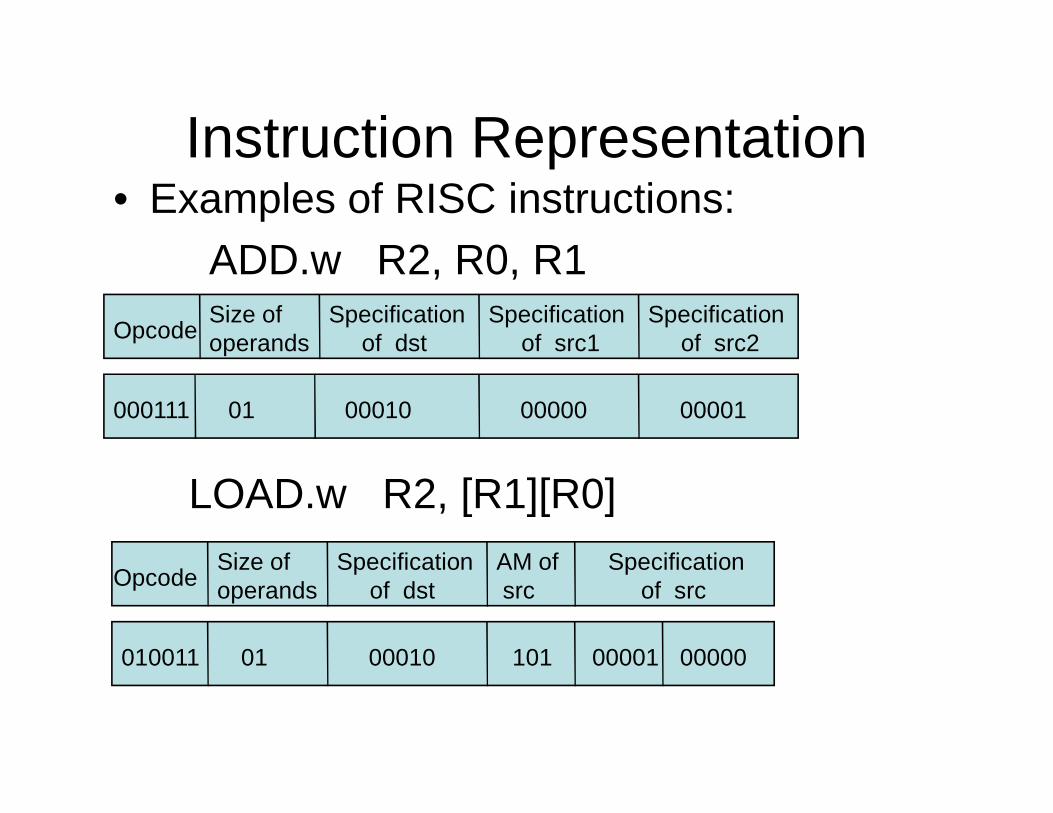
Instruction Representation• Examples of RISC instructions:
ADD.w R2, R0, R1
Opcode Specification
of srcSize of operands
AM ofsrc
Specification of dst
01 10100010 00000 00001
Opcode
000111
Specification of src1
Size of operands
Specification of dst
Specification of src2
00001 01 00010 00000
Opcode
000111
LOAD.w R2, [R1][R0]
010011
Opcode
Registers
• The registers set stores intermediate data used during the execution of the instructions
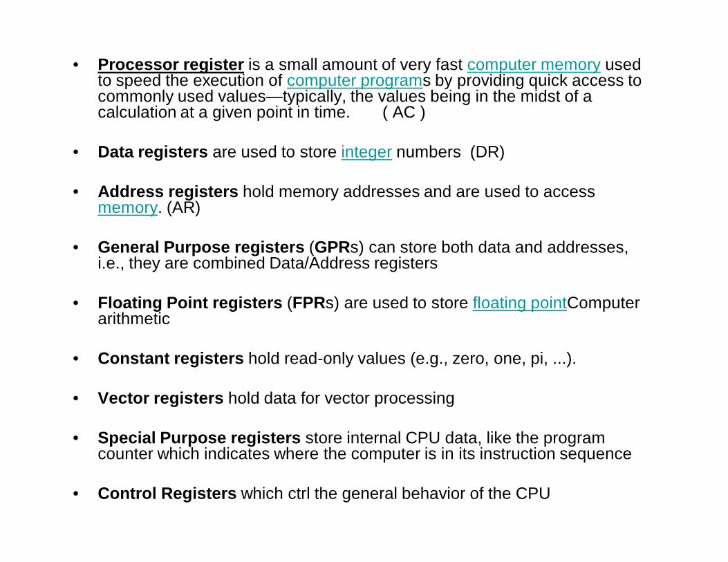
• Processor register is a small amount of very fast computer memory used to speed the execution of computer programs by providing quick access to commonly used values—typically, the values being in the midst of a calculation at a given point in time. ( AC )
• Data registers are used to store integer numbers (DR)
• Address registers hold memory addresses and are used to access memory. (AR)
• General Purpose registers (GPRs) can store both data and addresses, i.e., they are combined Data/Address registers
• Floating Point registers (FPRs) are used to store floating pointComputer arithmetic
• Constant registers hold read-only values (e.g., zero, one, pi, ...).
• Vector registers hold data for vector processing
• Special Purpose registers store internal CPU data, like the program counter which indicates where the computer is in its instruction sequence
• Control Registers which ctrl the general behavior of the CPU
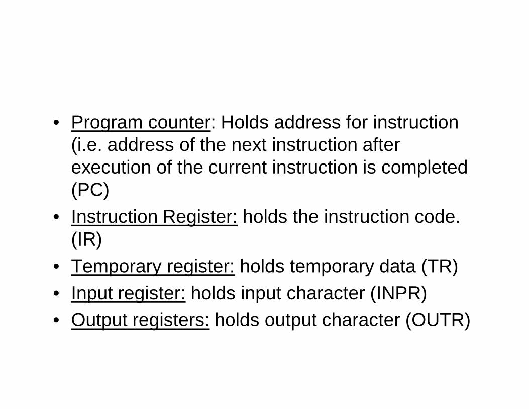
• Program counter: Holds address for instruction (i.e. address of the next instruction after execution of the current instruction is completed (PC)
• Instruction Register: holds the instruction code. (IR)
• Temporary register: holds temporary data (TR)• Input register: holds input character (INPR) • Output registers: holds output character (OUTR)
Instruction codes
• The internal organization of a digital system is defined by the sequence of micro operations it performs on data stored in its registers.
• Digital computer is capable of executing various micro operations & can be instructed as to what sequence of operations it must perform.
• The user of a computer can control the process by means of a program.
• A program is a set of instructions that specify the operations, operands, and the sequence by which processing has to occur.
• The data processing task maybe altered by specifying a new program with different instructions or specifying the same instructions with different data.
• A computer instruction is a binary code that specifies a sequence of micro operations for the computer. Instructions codes together with data are stored in memory.
• The computer reads each instruction from memory and places it in a control register. The control then interprets the binary code of the instruction and proceeds to execute it by issuing a sequence of micro operations .
• Every computer has its own instruction set. The ability to store and execute , the stored program concept, is the most important property of a general purpose computer.
• An instruction code is a group of bits that instruct the computer to perform a specific operation. It usually divided into two parts, each having its own particular interpretation.
• The most basic part of an instruction code is its operation part. The operation code of an instruction is a group of bits that define such operations as add, subtract, multiply, shift and complement.
• As an illustration, consider a computer with 64 distinct operations. One of them being an ADD operation. When this operation code is decoded in the control unit, the computer issues control signals to read an operand from memory and add the operand to a processor register.
• The relationship between a computer operation and a micro operation. An operation is a part of an instruction stored in computer memory. It is a binary code that tells the computer to perform a specific operation.
• The control unit receives the instruction from memory and interprets the computer code bits.
• It then issues a sequence of control signals to initiate micro operations in internal computer registers.
• For every operation code, the control issues a sequence of micro operations needed for the hardware implementation of the specified operation.
• For this reason, an operation code is sometimes called a macro operations because it specifies a set of micro operations.
• The operation part of an instruction code specifies the operation to be performed. This operation must be performed on some data stored in processor
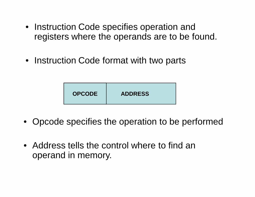
• Instruction Code specifies operation and registers where the operands are to be found.
• Instruction Code format with two parts
ADDRESSOPCODE
• Opcode specifies the operation to be performed
• Address tells the control where to find an operand in memory.
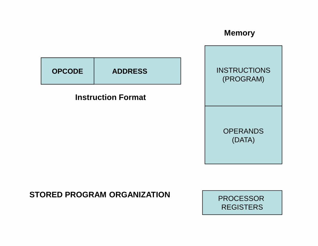
ADDRESSOPCODE INSTRUCTIONS(PROGRAM)
OPERANDS(DATA)
PROCESSOR REGISTERS
Instruction Format
Memory
STORED PROGRAM ORGANIZATION
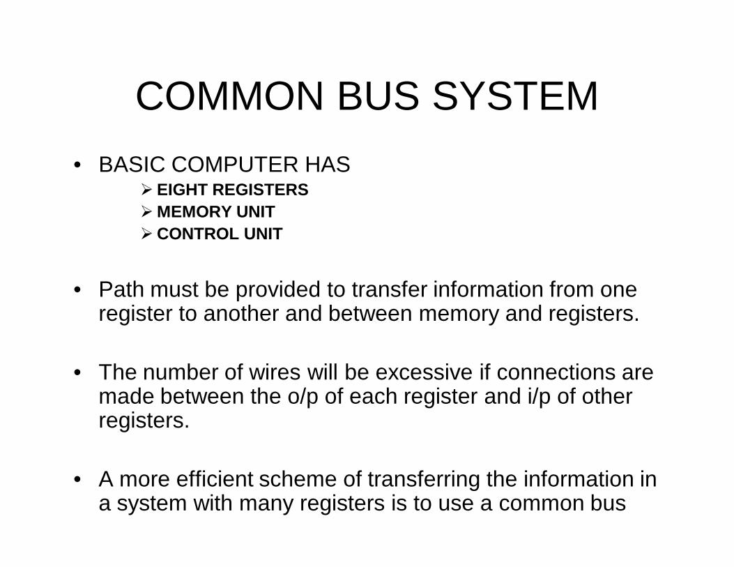
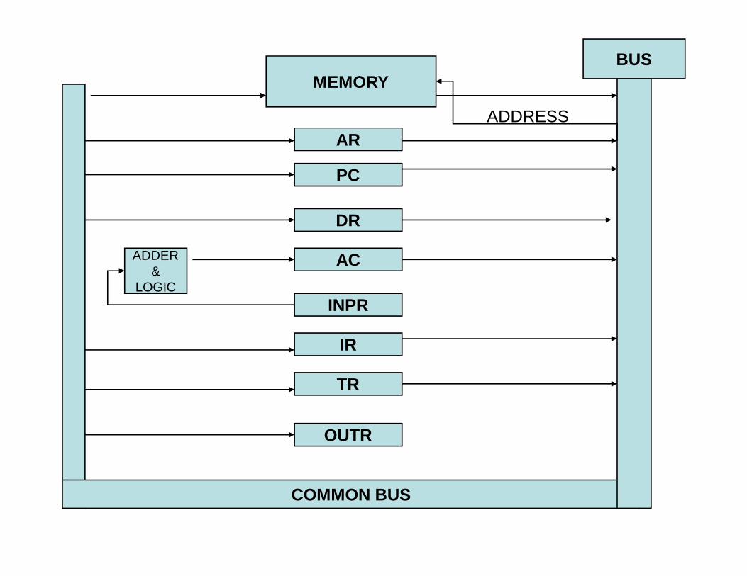
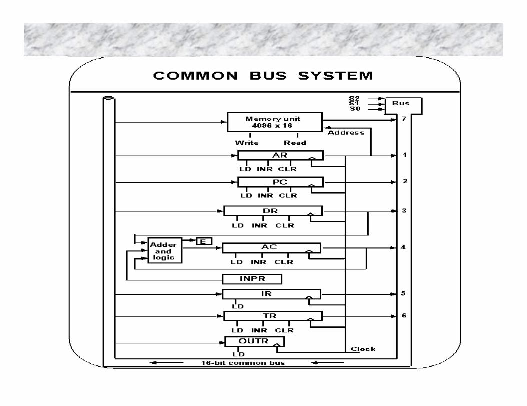
COMMON BUS SYSTEM• BASIC COMPUTER HAS
EIGHT REGISTERSMEMORY UNITCONTROL UNIT
• Path must be provided to transfer information from one register to another and between memory and registers.
• The number of wires will be excessive if connections are made between the o/p of each register and i/p of other registers.
• A more efficient scheme of transferring the information in a system with many registers is to use a common bus
COMMON BUS
BUSMEMORY
PC
DR
AC
INPR
IR
TR
OUTR
AR
ADDER&
LOGIC
ADDRESS
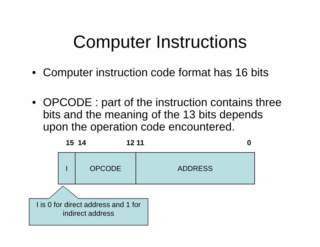
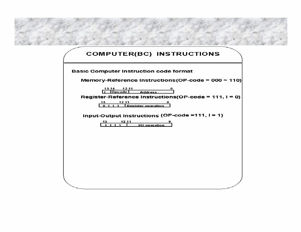
Computer Instructions• Computer instruction code format has 16 bits
• OPCODE : part of the instruction contains three bits and the meaning of the 13 bits depends upon the operation code encountered.
I OPCODE
15 14 12 11 0
ADDRESS
I is 0 for direct address and 1 for indirect address
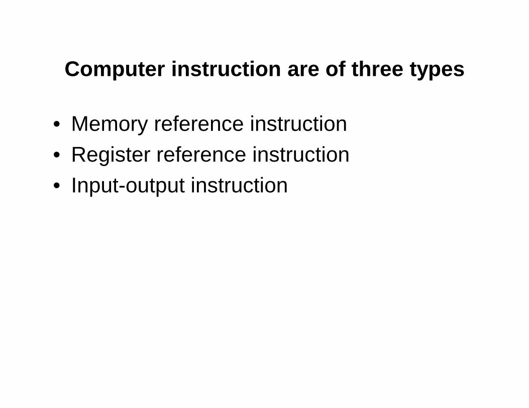
Computer instruction are of three types
• Memory reference instruction• Register reference instruction• Input-output instruction
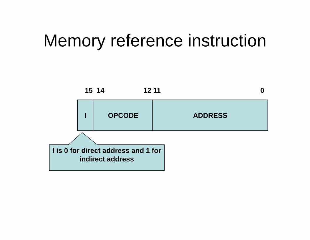
Memory reference instruction
I OPCODE
15 14 12 11 0
ADDRESS
I is 0 for direct address and 1 for indirect address
Register reference instruction
• They are recognized by the OPCOde 111 and 0 with the left most bit
• The other 12 bits specifies the operation.
• Register reference instruction specifies operation on register.
• So, does not need any reference to memory
Input-output instruction
• They are recognized by the OPCOde 111 and 1 with the left most bit
• The other 12 bits specifies the operation.
• Input-output instruction does not need any reference to memory
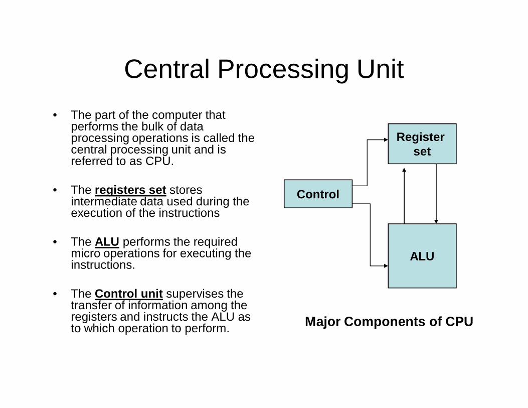
Central Processing Unit• The part of the computer that
performs the bulk of data processing operations is called the central processing unit and is referred to as CPU.
• The registers set stores intermediate data used during the execution of the instructions
• The ALU performs the required micro operations for executing the instructions.
• The Control unit supervises the transfer of information among the registers and instructs the ALU as to which operation to perform.
Control
ALU
Register set
Major Components of CPU
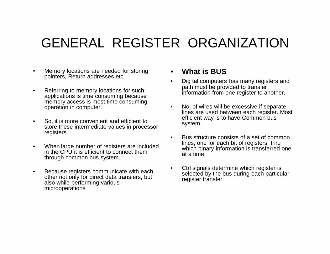
GENERAL REGISTER ORGANIZATION
• Memory locations are needed for storing pointers, Return addresses etc.
• Referring to memory locations for such applications is time consuming because memory access is most time consuming operation in computer.
• So, it is more convenient and efficient to store these intermediate values in processor registers
• When large number of registers are included in the CPU it is efficient to connect them through common bus system.
• Because registers communicate with each other not only for direct data transfers, but also while performing various microoperations
• What is BUS• Dig tal computers has many registers and
path must be provided to transfer information from one register to another.
• No. of wires will be excessive if separate lines are used between each register. Most efficient way is to have Common bus system.
• Bus structure consists of a set of common lines, one for each bit of registers, thru which binary information is transferred one at a time.
• Ctrl signals determine which register is selected by the bus during each particular register transfer
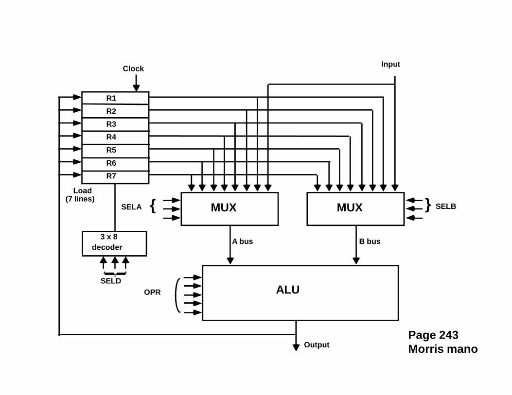
MUXSELA { MUX } SELB
ALUOPR
R1R2R3R4R5R6R7
Input
3 x 8decoder
SELD
Load(7 lines)
Output
A bus B bus
Clock
Page 243Morris mano
• General Register Organization:—• When a large number of registers are included
in the CPU, it is most efficient to connect them through a common bus system. The registers communicate with each other not only for direct data transfers, but also while performing various micro-operations. Hence it is necessary to provide a common unit that can perform all the arithmetic, logic and shift micro-operation in the processor.
• A Bus organization for seven CPU registers:—• Reference Diagram: Page Number 243 by M Morris Mano
• The output of each register is connected to true multiplexer (mux) to form the two buses A & B. The selection lines in each multiplexer select one register or the input data for the particular bus. The A and B buses forms the input to a common ALU. The operation selected in the ALU determines the arithmetic or logic micro-operation that is to be performed. The result of the micro-operation is available for output and also goes into the inputs of the registers. The register that receives the information from the output bus is selected by a decoder. The decoder activates one of the register load inputs, thus providing a transfer both between the data in the output bus and the inputs of the selected destination register.
• The control unit that operates the CPU bus system directs the information flow through the registers and ALU by selecting the various components in the systems.
• R1 R2 + R3• (1) MUX A selection (SEC A): to place the content of R2 into bus A• (2) MUX B selection (sec B): to place the content of R3 into bus B• (3) ALU operation selection (OPR): to provide the arithmetic addition (A + B)• (4) Decoder destination selection (SEC D): to transfer the content of the output
bus into R1• These form the control selection variables are generated in the control unit and must
be available at the beginning of a clock cycle.
ALU
• Arithmetic:• Addition, Subtraction, Multiplication,
Division• Logic:• Comparisons
Control Unit
• Reads & Interprets Program Instructions• Directs the Operation of the Processor• Controls the flow of programs and data
into and out of memory
• CU consists of two decoders, a counter and a number of ctrl logic gates.
• An instruction read from memory is placed in instruction register (IR) where it is divided into three parts:
• I bit• Opcode• 0-11 bits ----
• Operation code in bits 12 thru 14 are decoded with a 3*8 decoder
Central Processing Unit• Machine Cycle• Fetch• Decode• Execute• Store
• Fetch• Calls an instruction into
memory
• Decode• Figures out what the
instruction is trying to do
• Execute• Does the decoded instruction• Add 2+2
• Store• Puts the answer 4 into memory
for use by another instruction
Memory• Memory unit is needed for
storing programs and data.
• Memory units that communicate directly with CPU is called MAIN MEMORY
• Devices that provide backup storage is called auxiliary memory
• Most common auxiliary memory is magnetic disks and magnetic tapes. They are used for storing programs, large data files, and other backup information.
• Only programs and data that are currently needed by the processor will reside in main memory
• All other information is stored in auxiliary memory and transferred to main memory when needed
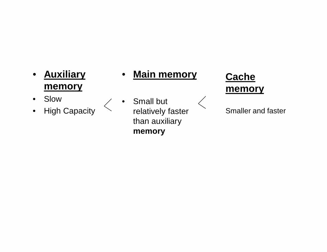
• Auxiliary memory
• Slow• High Capacity
• Main memory
• Small but relatively faster than auxiliarymemory
Cache memory
Smaller and faster
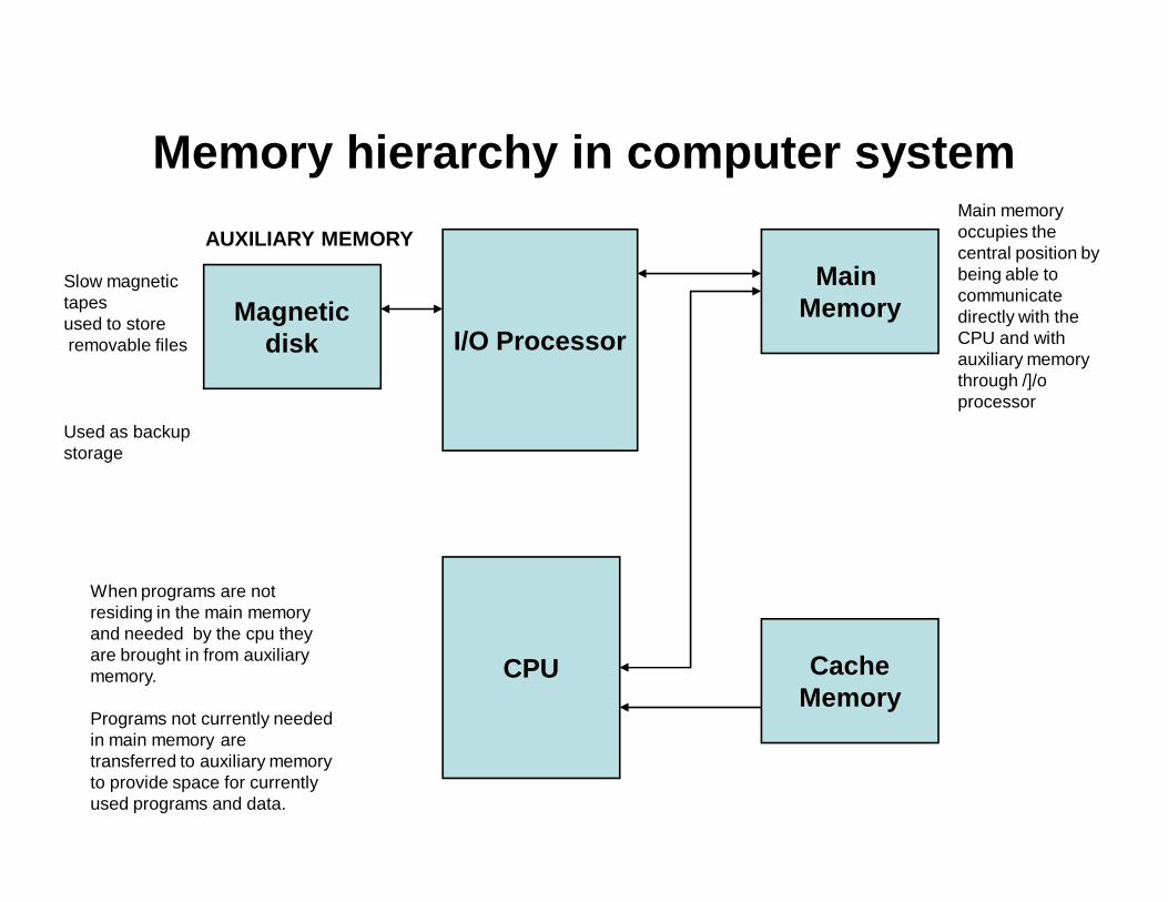
Memory hierarchy in computer system
Magneticdisk I/O Processor
CPU CacheMemory
Main Memory
Slow magnetic tapesused to storeremovable files
Used as backup storage
AUXILIARY MEMORYMain memory occupies the central position by being able to communicate directly with the CPU and with auxiliary memory through /]/o processor
When programs are not residing in the main memory and needed by the cpu they are brought in from auxiliary memory.
Programs not currently needed in main memory are transferred to auxiliary memory to provide space for currently used programs and data.
CACHE MEMORY• a special very high speed memory called is sometimes used to increase the speed of
the processing by making current programs and data available to the CPU at the rapid rate.
• The cache memory is employed in computer systems to compensate the speed differential between main memory access time and logic.
• CPU logic is usually faster than main memory access time, with the result that processing speed is limited primarily by the speed of the main memory.
• A Technique used to compensate for the mismatch in operating speeds is to employ an extremely fast, small cache between the CPU and main memory whose access time is close to processor logic clock cycle time.
• The cache is used for storing segments of programs currently being executed in the CPU and temporary data frequently needed in the present calculations
• By doing this the performance rate of the computer also increases
Main Memory / Primary Memory units
• RAM (Random Access Memory)• ROM (Read-only Memory)
• – They work in different ways and perform distinct functions• – CPU Registers• – Cache Memory
• • Also termed as ‘auxiliary’ or ‘backup’ storage, it is typically used as a• supplement to main storage. It is much cheaper than the main storage and• stores large amount of data and instructions permanently. Hardware
devices• like magnetic tapes and disks fall under this category.
Secondary Memory/Auxiliary Memory
• Also termed as ‘auxiliary’ or ‘backup’ storage, it is typically used as a supplement to main storage.
• It is much cheaper than the main storage and stores large amount of data and instructions permanently.
• Hardware devices like magnetic tapes and disks fall under this category
Random Access Memory• RAM or Random Access Memory is the
central storage unit in a computer system.
• It is the place in a computer where the operating system, application programs and the data in current use are kept temporarily so that they can be accessed by the computer’s processor.
• The more RAM a computer has, the more data a computer can manipulate.
• Random access memory, also called the Read/Write memory, is the temporary memory of a computer.
• It is said to be ‘volatile’ since its contents are accessible only as long as the computer is on.
• The contents of RAM are cleared once the computer is turned off.
• Types of RAM1. STATIC RAM2. DYNAMIC RAM
• STATIC RAM: CONSISTS OF INTERNAL FLIP FLOPS THAT STORES THE BINARY INFORMATION . The stored information remains valid as long as the power is applied to the unit.
• DYNAMIC RAM: stores the binary information in the form of electric charges that are applied to the capacitors. (capacitors are attached to transistors) The capacitors are provided by the inside the chip by the MOS (metal oxide transistor) transistors. The stored charge on the capacitors tend to discharge with time and the capacitors must be periodically recharged by refreshing the dynamic memory.
• Static memory is easy to use.
ROM• ROM or Read Only Memory is
a special type of memory which can only be read and contents of which are not lost even when the computer is switched off.
• It typically contains manufacturer’s instructions.
• Among other things, ROM also stores an initial program called the ‘bootstrap loader’ whose function is to start the computer software operating, once the power is turned on.
• Contents of ROM remains unchanged after the power is turned off and on again.
• Read-only memories can be manufacturer-programmed or user-programmed.
• PROM• While manufacturer-programmed
ROMs have data burnt into the circuitry, user programmed ROMs can have the user load and then store read-only programs.
• EPROM • Information once stored on the
ROM or PROM chip cannot be altered. However, another type of memory called EPROM (Erasable PROM) allows a user to erase the information stored on the chip and reprogram it with new information.
ROM Types
• PROM• EPROM• EEPROM
• Each type has unique characteristics, but they are all types of memory with two things in common:
• Data stored in these chips is nonvolatile -- it is not lost when power is removed.
• Data stored in these chips is either unchangeable or requires a special operation to change (unlike RAM, which can be changed as easily as it is read).
• ROM chips are fundamentally different from RAM chips. While RAM uses transistors to turn on or off access to a capacitor at each intersection, ROM uses a diode
AUXILIARY MEMORY
• RAM is volatile memory having a limited storage capacity. Secondary/auxiliary storage is storage other than the RAM.
• These include devices that are peripheral and are connected and controlled by the computer to enable permanent storage of programs and data.
• The memory is specifically meaning the RAM. This keeps the information for a shorter period of time (usually volatile), is faster and more expensive.
• By Storage we mean the Hard disk. Here the information is retained longer (nonvolatile), It’s Slower and Cheaper
Auxiliary Storage Devices-Magnetic Tape, Floppy Disk, Hard Disk.
• The Magnetic Storage Exploits duality of magnetism and electricity. It converts electrical signals into magnetic charges, captures magnetic charge on a storagemedium and then later regenerates electrical current from stored magnetic charge.Polarity of magnetic charge represents bit values zero and one.
• Magnetic Disk• The Magnetic Disk is Flat, circular platter with metallic
coating that is rotated beneath read/write heads. It is a Random access device; read/write head can be moved to any location on the platter.
Floppy Disk
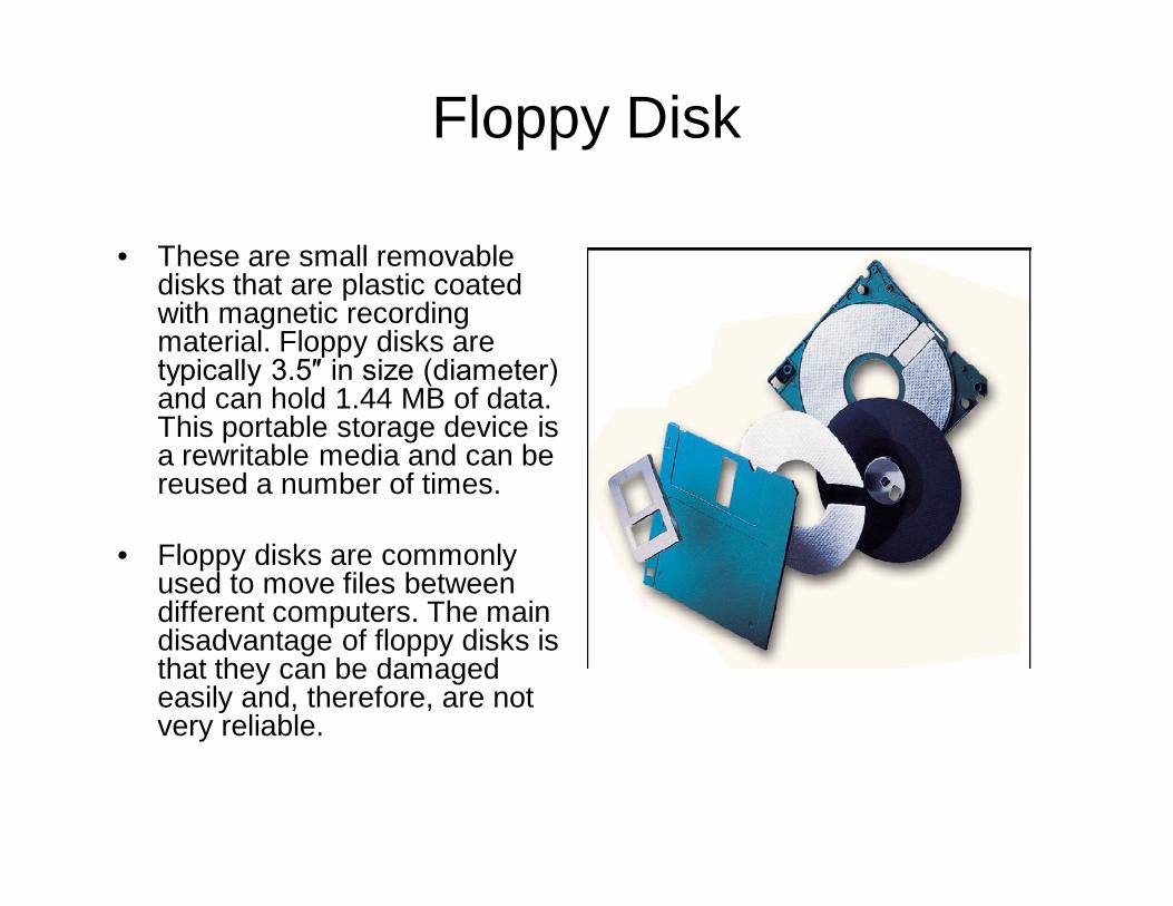
• These are small removable disks that are plastic coated with magnetic recording material. Floppy disks are typically 3.5″ in size (diameter) and can hold 1.44 MB of data. This portable storage device is a rewritable media and can be reused a number of times.
• Floppy disks are commonly used to move files between different computers. The main disadvantage of floppy disks is that they can be damaged easily and, therefore, are not very reliable.
HARD DISK
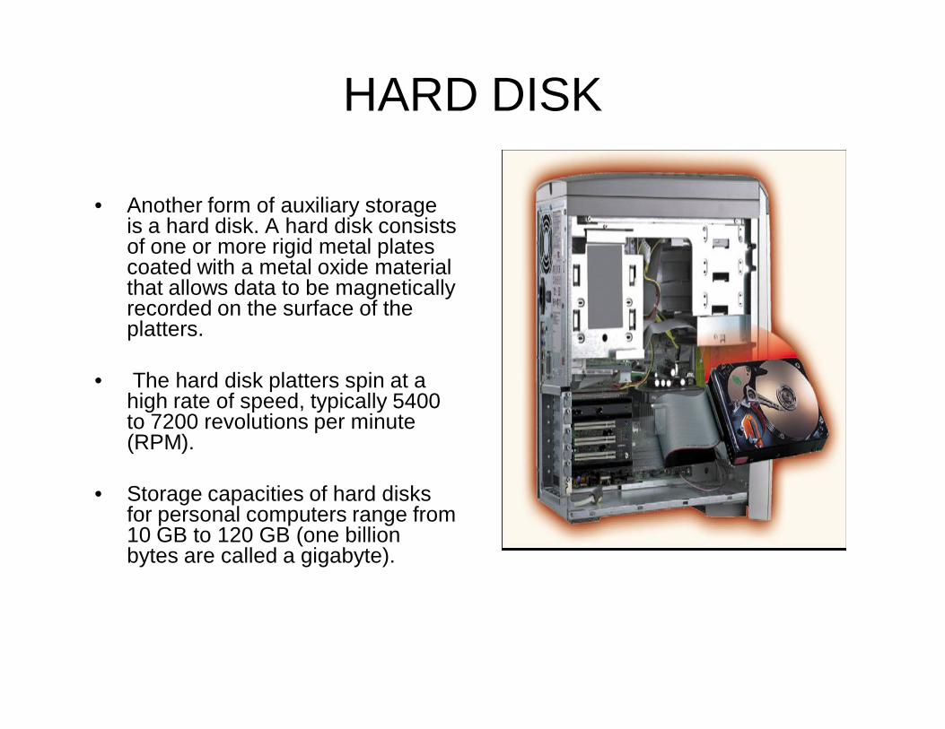
• Another form of auxiliary storage is a hard disk. A hard disk consists of one or more rigid metal plates coated with a metal oxide material that allows data to be magnetically recorded on the surface of the platters.
• The hard disk platters spin at a high rate of speed, typically 5400 to 7200 revolutions per minute (RPM).
• Storage capacities of hard disks for personal computers range from 10 GB to 120 GB (one billion bytes are called a gigabyte).
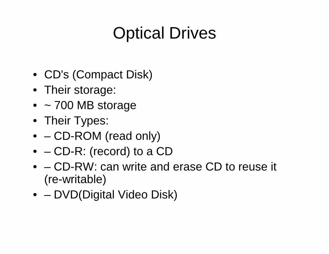
Optical Drives
• CD's (Compact Disk)• Their storage:• ~ 700 MB storage• Their Types:• – CD-ROM (read only)• – CD-R: (record) to a CD• – CD-RW: can write and erase CD to reuse it
(re-writable)• – DVD(Digital Video Disk)
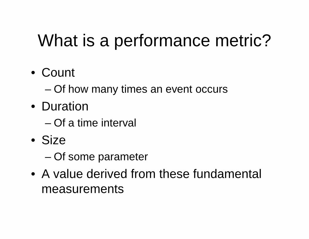
What is a performance metric?
• Count– Of how many times an event occurs
• Duration– Of a time interval
• Size– Of some parameter
• A value derived from these fundamental measurements
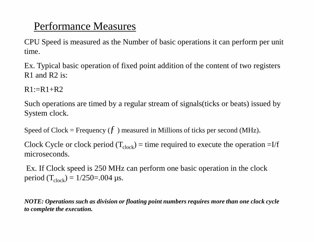
Performance MeasuresCPU Speed is measured as the Number of basic operations it can perform per unit time.
Ex. Typical basic operation of fixed point addition of the content of two registers R1 and R2 is:
R1:=R1+R2
Such operations are timed by a regular stream of signals(ticks or beats) issued by System clock.
Speed of Clock = Frequency (ƒ ) measured in Millions of ticks per second (MHz).
Clock Cycle or clock period (Tclock) = time required to execute the operation =I/f microseconds.
Ex. If Clock speed is 250 MHz can perform one basic operation in the clock period (Tclock) = 1/250=.004 µs.
NOTE: Operations such as division or floating point numbers requires more than one clock cycle to complete the execution.
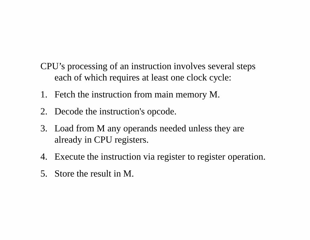
CPU’s processing of an instruction involves several steps each of which requires at least one clock cycle:
1. Fetch the instruction from main memory M.
2. Decode the instruction's opcode.
3. Load from M any operands needed unless they are already in CPU registers.
4. Execute the instruction via register to register operation.
5. Store the result in M.
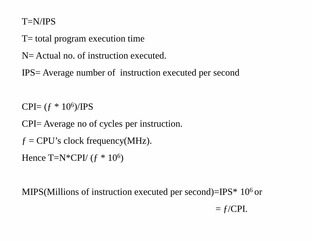
T=N/IPS
T= total program execution time
N= Actual no. of instruction executed.
IPS= Average number of instruction executed per second
CPI= (ƒ * 106)/IPS
CPI= Average no of cycles per instruction.
ƒ = CPU’s clock frequency(MHz).
Hence T=N*CPI/ (ƒ * 106)
MIPS(Millions of instruction executed per second)=IPS* 106 or
= ƒ/CPI.
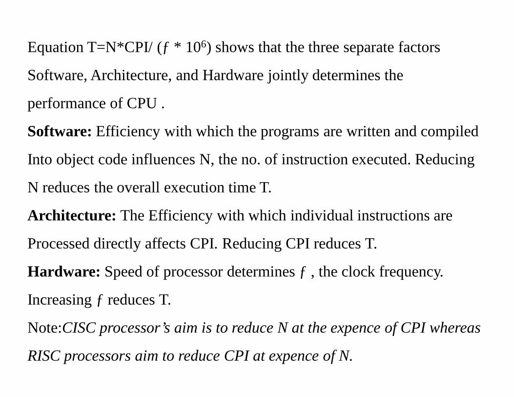
Equation T=N*CPI/ (ƒ * 106) shows that the three separate factors
Software, Architecture, and Hardware jointly determines the
performance of CPU .
Software: Efficiency with which the programs are written and compiled
Into object code influences N, the no. of instruction executed. Reducing
N reduces the overall execution time T.
Architecture: The Efficiency with which individual instructions are
Processed directly affects CPI. Reducing CPI reduces T.
Hardware: Speed of processor determines ƒ , the clock frequency.
Increasing ƒ reduces T.
Note:CISC processor’s aim is to reduce N at the expence of CPI whereas
RISC processors aim to reduce CPI at expence of N.
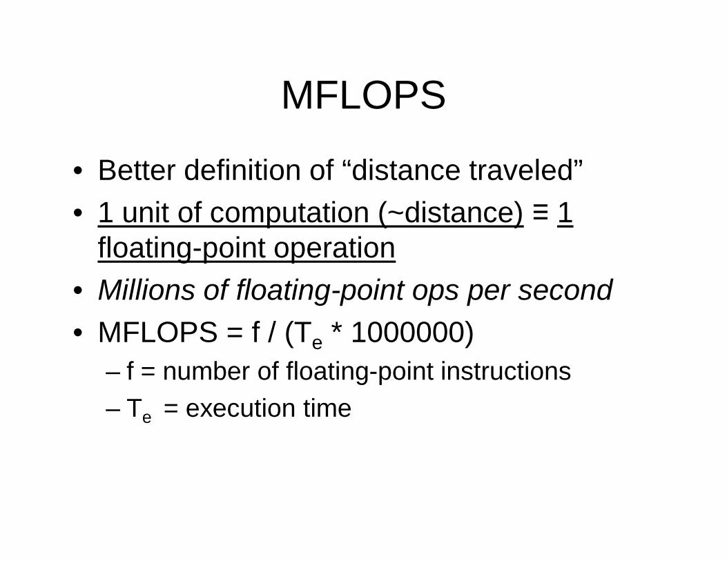
MFLOPS
• Better definition of “distance traveled”• 1 unit of computation (~distance) ≡ 1
floating-point operation• Millions of floating-point ops per second• MFLOPS = f / (Te * 1000000)
– f = number of floating-point instructions– Te = execution time