Embed Size (px)
Citation preview

Stops & Goes of Traffic SignalsA Traffi c Signal Auditors’ Perspective
November 2004

Stops & Goes of Traffi c Signals • A Traffi c Signal Auditors’ Perspective - November 2004
ISBN 0-478-25367-2
© 2004, Transfund New ZealandP O Box 2331, Wellington, New ZealandTelephone +64 (04) 916 4220 Facsimile +64 (04) 916 0028
Transfund New Zealand. Stops & Goes of Traffi c Signals. November 2004 Transfund New Zealand, Wellington, New Zealand
Keywords: Safety, audit, road engineering, traffi c engineering, pedestrian, cycling, cyclist, procedures, audit team, standards, guidelines, intersection, traffi c signal, traffi c light, crashes, effi ciency, signal audit, review.

Stops & Goes of Traffi c Signals • A Traffi c Signal Auditors’ Perspective - November 2004
1 • PREFACE 1
2 • INTRODUCTION 2
3 • SPECIALISED TASKS 3
3.1 • Traffi c Signal Peer Reviews 3
3.2 • Intersection Control 3
3.3 • Contact Details 3
4 • CRASHES AT TRAFFIC SIGNALS 4
4.1 • Factors contributing to Right-Turn-Against crashes 4
4.2 • Factors contributing to Red Light Running 5
4.3 • Observations on Cyclist Crashes 5
4.4 • Observations on Pedestrian Crashes 5
5 • INTERSECTION AND LANE LAYOUT 6
5.1 • Opposed Right Turn Lanes 6
5.2 • Captive Turn Lanes 7
5.3 • Slip Lanes 8
6 • SIGNAL POST AND DISPLAY LOCATION 9
6.1 • Post Placement and Signal Conspicuity 9
6.2 • Suffi cient Stopping and Manoeuvring Displays 10
7 • PHASING AND OPERATIONAL ISSUES 11
7.1 • Right turn and left turn arrow operation 11
7.2 • Turn arrow logic 12
8 • PEDESTRIAN ISSUES 14
8.1 • Pedestrian Phase Issues 14
8.2 • Push Button Location 15
9 • CYCLIST ISSUES 16
9.1 • Provision for Cyclists 16
10 • CONCLUSIONS 18
11 • ACKNOWLEDGEMENTS 19
11 • REFERENCES 20
• TABLE OF CONTENTS
Stops & Goes of Traffi c Signals • A Traffi c Signal Auditors’ Perspective - November 2004
1 • PREFACE
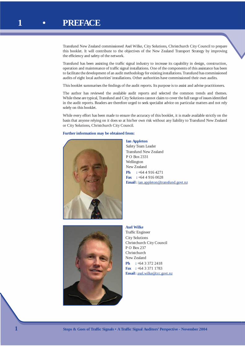
Transfund New Zealand commissioned Axel Wilke, City Solutions, Christchurch City Council to prepare this booklet. It will contribute to the objectives of the New Zealand Transport Strategy by improving the effi ciency and safety of the network.
Transfund has been assisting the traffi c signal industry to increase its capability in design, construction, operation and maintenance of traffi c signal installations. One of the components of this assistance has been to facilitate the development of an audit methodology for existing installations. Transfund has commissioned audits of eight local authorities’ installations. Other authorities have commissioned their own audits.
This booklet summarises the fi ndings of the audit reports. Its purpose is to assist and advise practitioners.
The author has reviewed the available audit reports and selected the common trends and themes. While these are typical, Transfund and City Solutions cannot claim to cover the full range of issues identifi ed in the audit reports. Readers are therefore urged to seek specialist advice on particular matters and not rely solely on this booklet.
While every effort has been made to ensure the accuracy of this booklet, it is made available strictly on the basis that anyone relying on it does so at his/her own risk without any liability to Transfund New Zealand or City Solutions, Christchurch City Council.
Further information may be obtained from:
Ian AppletonSafety Team LeaderTransfund New ZealandP O Box 2331WellingtonNew Zealand Ph : +64 4 916 4271 Fax : +64 4 916 0028 Email : [email protected]
1
Axel WilkeTraffi c EngineerCity SolutionsChristchurch City CouncilP O Box 237ChristchurchNew ZealandPh : +64 3 372 2418Fax : +64 3 371 1783Email : [email protected]

Stops & Goes of Traffi c Signals • A Traffi c Signal Auditors’ Perspective - November 2004 2
The ‘Signals New Zealand User Group’ (SNUG) has identifi ed a need to achieve better consistency with the design and operation of traffi c signals throughout the country. Transfund funded the development of a signal audit methodology, where safety and effi ciency of traffi c signals are examined. A representative number of signal installations, in the area covered by nine territorial local authorities (TLAs), were audited by April 2004. All audits included signals administered by the TLAs on behalf of Transit New Zealand (Transit), the road controlling authority (RCA) for State Highways.
A review of all nine audit reports has been carried out with the key results summarised in this booklet. Practices in need of improvement are illustrated and commented on, and backed up with examples of good design.
The purpose of this booklet is to draw attention to those elements of traffi c signals that the auditors have frequently found to compromise safety and/or effi ciency, and to present ways in which these defi ciencies could be addressed. Appropriate standards and guidelines are in place, with Austroads Part 7 (2003) being the main reference document.
The target audience group for this booklet is engineers who design, construct, install, manage and maintain traffi c signals. Therefore the document will contain traffi c signal terminology, which will not be explained in this booklet but may be found in the glossary of terms in Austroads Part 7 (2003).
Section 4 of this booklet details a national analysis of crashes at traffi c signals and the defi ciencies that may have contributed to these crash patterns. This analysis was undertaken by Tim Hughes of the Land Transport Safety Authority (LTSA).
The aim of this booklet is to contribute to safer and more effi cient installations and operations of traffi c signals in New Zealand.
2 • INTRODUCTION

Stops & Goes of Traffi c Signals • A Traffi c Signal Auditors’ Perspective - November 2004
3 • SPECIALISED TASKS
3.1 Traffi c signal peer reviewsWhile the audit process reviews the existing installations, it does not cover any new installations or major upgrades of existing sites. Therefore Transfund and SNUG have been promoting a parallel process of traffi c signal peer reviews to ensure best engineering practice is used at every new installation or major intersection upgrade. This recommendation recognises traffi c signal design is a highly specialised discipline of traffi c engineering, and that there are few engineers in New Zealand with the appropriate in-depth knowledge and experience.
It should be stressed that a traffi c signal peer review is not covered by the road safety audit process(Transit New Zealand, 1993). Traffi c signal peer review covers both safety and effi ciency, and should be undertaken by a competent signals engineer.
It is recommended that RCAs add the requirement for a traffi c signal peer review to the Austroads Part 7 (2003) design process fl ow chart (Table 1.1).
3.2 Intersection controlThe set-up of the SCATS software used for operating traffi c signals is a specialised discipline. It is recommended suitably qualifi ed engineers should be engaged periodically to review the set-up of SCATS networked traffi c signals.
Another specialised fi eld is the programming of the traffi c signal controllers. RCAs should ensure a suitably qualifi ed and experienced engineer is employed for this task.
3.3 Contact detailsPlease contact any SNUG committee member for a list of suitably qualifi ed and experienced engineers. Contact details for SNUG committee members can be found on www.ipenz.org.nz/snug/.
3

Stops & Goes of Traffi c Signals • A Traffi c Signal Auditors’ Perspective - November 2004
An analysis undertaken by Tim Hughes from the LTSA identifi ed the main safety issues at traffi c signals as follows:
• right-turn-against crashes 32%• failed to stop for red 30%• pedestrians 14%• cyclists 8%
Subsequent sections of this guide will give some guidance on how the safety performance of signals can be improved.
4.1 Factors contributing to right-turn-against crashesThe following factors can contribute to right–turn-against crashes:
• compromised visibility due to geometry.• misjudging speed, especially on multilane roads.• turning on yellow when one lane has stopped, but drivers in adjacent lanes proceed.• misjudging intentions of opposing traffi c – through or turning left?• use of phasing and arrows.
Compared to full fi ltering, the following crash rate reductions have been identifi ed (Hall, 1993):
• 30% for fi lter right turns, followed by a right turn arrow (a lag right turn).
• 68% for a right turn arrow, followed by fi ltering (a lead right turn).
• 90% for a lead right turn, followed by a red arrow (no fi lter).
4
4 • CRASHES AT TRAFFIC SIGNALS

Stops & Goes of Traffi c Signals • A Traffi c Signal Auditors’ Perspective - November 20045
4.2 Factors contributing to red light runningThe following factors can contribute to unintentional red light running:
• Poor conspicuity of signal displays• Other lights creating a background distraction• Anticipation of phase progression• Inconsistent phasing at adjacent intersections
In addition, drivers may be tempted into intentional red light running when they experience a poor level of service, especially when combined with a low expectation of enforcement.
4.3 Observations on cyclist crashes• In three quarters of the cases, the crashes are caused by motorists.• Cyclists would benefi t by having space allocated to them (especially for the through movement)
and colour highlighting that space.• A simplifi cation of the Give Way rules would help.
4.4 Observations on pedestrian crashes• Wide intersections intimidate pedestrians.• Drivers are often distracted (from seeing pedestrians) by other vehicles.• Slip lanes are generally safe for pedestrians (but large radii should be avoided).• A simplifi cation of the Give Way rules would help.

Stops & Goes of Traffi c Signals • A Traffi c Signal Auditors’ Perspective - November 2004
5 • INTERSECTION AND LANE LAYOUT
5.1 Opposed right turn lanesExclusive right turn lanes should be provided whenever possible. Opposed right turn lanes should line up, and not be offset, allowing right turners waiting for a fi lter turn as much forward visibility past queued opposing right turners as possible.
Many 14 m carriageways had their two-lane shared approaches reconfi gured to include an exclusive right turn lane, without relocating the centre line. This resulted in the opposed right turn lanes being offset.
Safety and effi ciency issuesPoorly aligned right turn lanes can lead to:
• poor inter-visibility between right turners and opposing through traffi c, resulting in a higher right-turn-against crash rate
• drivers concentrating too much on opposing through traffi c, overlooking pedestrians or cyclists to whom they must also give way
• some drivers being hesitant, reducing intersection capacity• increased inter-green time due to the longer tracking paths.
Recommended treatments• Ensure right turn bays line up (i.e. ‘back to back’ design).• Reducing the right turn lane width minimises the offset between opposed right turners, further
increasing forward-visibility.• Where opposed right turn lanes are not possible (e.g. due to the inability to ban kerbside parking
or tracking paths of vehicles), consider a different phasing operation (e.g. split approaches) or a right turn ban for one direction.
6
Figure 1 : Offset right turn bays (and hidden primary lantern).
Figure 2 : Right turn bays incorporated into solid median achieving excellent forward-visibility.

Stops & Goes of Traffi c Signals • A Traffi c Signal Auditors’ Perspective - November 2004
5.2 Captive turn lanesCaptive turn lanes are created when a mid-block through lane leads directly into a turn lane at an intersection. It is important that advanced warning is given to motorists that they may only turn from these lanes.
Ideally, drivers should be channelled into through lanes at intersections (or shared through and turn lanes) and should not be confronted with captive turn lanes.
Captive turn lanes with insuffi cient warning were found quite frequently during the signal audits and they appear to be a result of the engineering plans not showing how to tie the intersection lane layout into the existing mid-block markings.
Safety and effi ciency issuesCaptive turn lanes can lead to:
• erratic and undesirable driver behaviour, including sudden lane changes or through movements when only turning movements are allowed, potentially resulting in a higher crash rate
• drivers unnecessarily slowing or stopping close to the intersection for a desired lane change, impacting on the intersection capacity.
Recommended treatments• Channel drivers into through lanes whenever possible (ensure that engineering plans show the tie-in
into the mid-block layout).• Where captive lanes cannot be avoided (e.g. where two approach lanes in the mid-block lead into the
stem of a T intersection with exclusive turning lanes), ensure that drivers have suffi cient pre-warning by lane arrows and possibly signs.
7
Figure 3 : Captive left turn lane with insuffi cient warning to motorists.
Figure 4 : Lane markings advising motorists of captive turn lanes.

Stops & Goes of Traffi c Signals • A Traffi c Signal Auditors’ Perspective - November 2004 8
5.3 Slip lanesSlip lanes help to make intersections more compact, and enable traffi c signal posts and lanterns to be placed closer to the drivers’ line of sight. Decision making processes for motorists are generally simplifi ed, resulting in a safer intersection layout. Whilst some pedestrians voice reservations about slip lanes, they do remove the confl ict that occurs when left turners and parallel pedestrians proceed together.
Slip lanes should comply in layout with guidance given in Austroads Part 5 (1988). For sign posting details and provisions for visually impaired pedestrians, refer to RTS 9 (Guidelines for the Signing and Layout of Slip Lanes, 1993) and RTS 14 (Guidelines for facilities for blind and vision-impaired pedestrians, 2003), respectively.
Safety and effi ciency issuesPoorly designed slip lanes can lead to the following problems:
• Poor inter-visibility between pedestrians and left turners, if the crossing position is too far around the corner.• Drivers having problems observing traffi c to give way to if the slip lanes are not of the high-entry
angle type, or if the kerb radii are too large (because some people have problems turning their heads and door pillars may obstruct visibility). Driver hesitance and increased crash rate are possible consequences.
• Increased turning speeds, resulting in loss of control or failure to give way.• Not enough room for pedestrians (e.g. during the school peak) or street furniture, if islands are undersized.
Recommended treatments• Slip lanes should be of appropriate size and of a high-entry-angle type, with adequate corner radii.• The location of the pedestrian crossing point should provide suffi cient intervisibility.• Pedestrian priority issues can be addressed using a signalised slip lane crossing, or a priority (zebra)
crossing (possibly on a raised platform).
Figure 5 : Pedestrian crossing around the corner – poor visibility.
Figure 6 : Slip lane with zebra crossing on raised platform for speed control.

Stops & Goes of Traffi c Signals • A Traffi c Signal Auditors’ Perspective - November 2004
6 • SIGNAL POST AND DISPLAY LOCATION
6.1 Post placement and signal conspicuitySignal faces have different functions. Motorists get information that warn them, make them stop, indicate when to start again, and what manoeuvres can be undertaken. Safety is reduced if signal faces are not clearly visible from the appropriate distance.
One of the most common safety audit fi ndings was that of signals with inadequate conspicuity. When this lack of conspicuity includes the signal faces that perform the warning and stopping functions, safety is reduced as a consequence.
Safety and effi ciency issuesPoor post placement and reduced signal conspicuity can lead to:
• an increase in inadvertent red light running• an increase in rear end crashes• an increase in right turn against crashes• reduced effi ciency.
Recommended treatments• RCAs should have an upgrading programme for conversion to tall (5 m) posts or mast arms as appropriate.• Kerbside posts should be located nominally 1 m (and no less than 0.6 m) from the kerb face, and close
to the tangent point. Minimising corner radii can help achieve this.• Kerb extensions should be used wherever possible to improve lantern visibility.• Street furniture should not reduce signal conspicuity. Under-grounding aerial services, locating street
lighting poles at the property boundary, and the use of joint-use poles can all be considered. The size of trees must be taken into account both at the time of planting, and at maturity, and on-going maintenance (pruning, trimming) allowed for.
9
Figure 7 : No signals visible to approaching drivers.
Figure 8 : Good conspicuity of traffi c signals.
Stops & Goes of Traffi c Signals • A Traffi c Signal Auditors’ Perspective - November 2004 10
6.2 Suffi cient stopping and manoeuvring displaysMotorists must receive the relevant information from signal displays, regardless of which lane they are travelling in. Some redundancy has to be designed into the system, as lamps can fail and the remaining signals must still provide a safe intersection. Legislated minimum requirements also need to be met.
Safety and effi ciency issuesAn insuffi cient number of signal displays can lead to:
• compromised signal conspicuity (for motorists in some traffi c lanes, for example caused by large vehicles in adjacent lanes) and thus reduced safety
• motorists making wrong choices• unsafe intersection operation in case of lamp failure• RCAs opening themselves to avoidable risks when legislated requirements are not met.
Recommended treatments• At a minimum, all displays must be provided in the primary or dual primary position
(including arrow displays).• The minimum number of signal displays for major and minor movements is three and two,
respectively. A right or left turning movement that is (at least partially) allowed to fi lter is a minor movement, and a right turning movement that is fully protected is classed as a major movement.
• On multi-lane approaches, one signal face is suffi cient for two lanes only.• At least one aspect must be illuminated in any one signal face at any one time (i.e. avoid signal faces
with three arrow aspects only where fi lter turning occurs, as all aspects will be in the OFF state during fi lter turning).
Figure 9 : Non-complying two-aspect display (green missing).
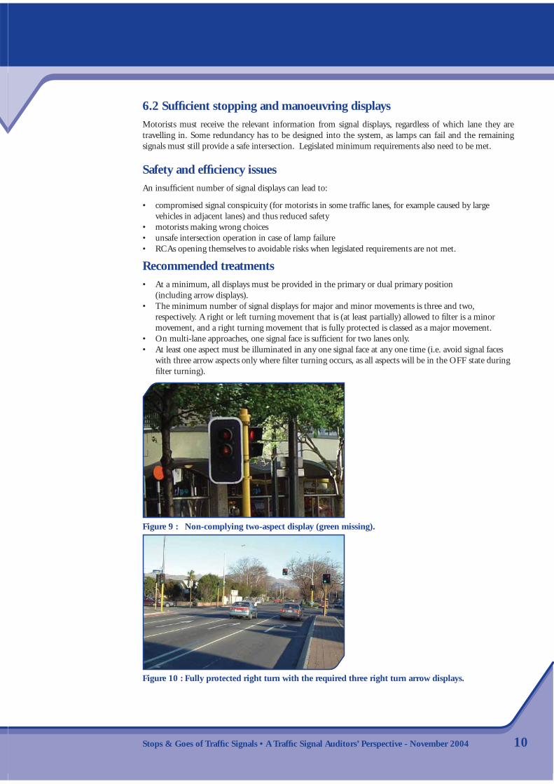
Figure 10 : Fully protected right turn with the required three right turn arrow displays.

Stops & Goes of Traffi c Signals • A Traffi c Signal Auditors’ Perspective - November 2004
7 • PHASING AND OPERATIONAL ISSUES
7.1 Right turn and left turn arrow operationThe objectives of signal phasing design are to provide safety and effi ciency. As those objectives often confl ict, compromises must be considered carefully. Right turn arrows can be used for partial or full control of that movement. Left turn arrows allow motorists to move when there is no confl ict (e.g. from a side street during a diamond phase operation on the main road). Arrows are also useful for partial or full pedestrian protection (e.g. when a turning movement is held back for at least part of the time for parallel pedestrians crossing the road). Left turn arrows are used to indicate to motorists when they have to give way to opposing right turn traffi c. The left turn arrows are in the OFF state when fi ltering is permitted, and the left turn green arrow is illuminated when no opposing right turn or pedestrian movement is allowed.
There are a variety of reasons why, in some circumstances, a lag right turn at cross intersections is less safe than a lead right turn, and the default should be a lead right turn arrangement (refer Section 4). A lag right turn may be dictated by co-ordination requirements, or when insuffi cient width does not allow opposing right turning movements to occur simultaneously.
Particular care must be taken to avoid phasing an unintentional lag right turn when the opposing right turn movement may fi lter-turn. This ‘right-turn trap’ happens when a fi lter right turner (or a u-turner at a T intersection) faces a yellow circle display, but the opposing through movement overlaps to a lag right turn phase. The right turner (or u-turner at a T intersection) has no indication whatsoever that the opposing through movement is not being terminated and may turn during the amber believing the opposing through movement is stopped. This situation can occur when intervening phases are skipped, e.g. during low demand periods.
Safety and effi ciency issuesThe following safety and effi ciency issues can arise:
• The use of arrow displays needs to balance safety and effi ciency• When consistency across the network is not met, motorists may be confused. Care should be taken
to ensure that similar phasing philosophies are used at adjacent intersections and preferably throughout the network
• The phasing design has to match the lane arrangement. A protected right turn phase requires an exclusive right turn lane (with the exception of split-approach phasing)
• A protected turn phase can only be operated when there is no confl ict. It is not considered good practice to have protected but opposing movements turn into their respective nearest lanes (i.e. a left turn green arrow and an opposing right turn green arrow should not be displayed together unless the departure lanes are physically separated by means of a solid island)
• Right turners ‘cutting the corner’ may drive over the right hand approach lane of the side street causing an unwanted side street demand.
Recommended treatments• Where arrow displays are present, they should always be used for full or partial pedestrian protection.• The controller personality must be set-up so that an unintentional and dangerous lag right turning
sequence is not possible. • Use a presence timer on the side street detector if it may be driven over by right turning traffi c from
the main road or offset the stoplines on the departure approach further back so the right turner does not encroach over the centreline.
11

Stops & Goes of Traffi c Signals • A Traffi c Signal Auditors’ Perspective - November 2004 12
7.2 Turn arrow logicOnly experienced signal designers and operators are likely to be aware of problems with turn arrow logic. Expert assistance is required in the design stage for both the physical intersection layout and phasing design. After installation the on-street operation should be checked by a suitably experienced signal engineer. Only suitably knowledgeable and experienced engineers should be used for compiling the controller personality.
Where an opposing right turning movement is held on a red arrow, a green left turn arrow (when present) should indicate to approaching motorists that they have priority over the opposing right turn movement. This is especially important when the opposing movement is allowed to fi lter turn some of the time in which case the left turn display should be in the OFF state.
Similarly, where the signal hardware is available, a green left turn arrow should be displayed to the side street traffi c when the main street operates a protected right turn.
When a left turn is associated with a right turn phase, it is good practice for the left turn detector to also call the right turn phase. This results in greater effi ciency as just one of the main road approaches needs to be stopped whenever there are only left turn vehicles.
There are some standard operating procedures for turn arrow logic (Austroads Part 7, 2003), including holding the right turn red arrow for fi ve seconds before dropping it when changing from a protected turn to a fi lter turn, and bringing a red arrow up at the same time as the adjacent full red.
Figure 11 : Bad practice of allowing protected turns into their own lanes simultaneously.
Figure 12 : Avoid a ‘right turn trap’ for u-turners on the north approach by either banning that u-turn, or by ensuring that A phase is never followed by B phase.

Stops & Goes of Traffi c Signals • A Traffi c Signal Auditors’ Perspective - November 2004
Safety and effi ciency issuesThe following safety and effi ciency issues can arise:
• when left turn arrows are not operated, motorists may be confused, or may not turn when they have no confl ict
• if the side street demand can be met by a left turn green arrow, then this would be the most effi cient way to operate the intersection.
Recommended treatments• The correct sequence for a transition from a protected right turn to a fi lter turn involves holding the
red arrow for fi ve seconds before it is dropped.• If present, green left turn arrows should be operated whenever that movement is unopposed.• A left turn loop should call an associated right turn movement (but special provisions must be allowed
for if force skipping the right turn phase via SCATS).• Standard operating sequences should be adhered to. • Seek expert help and ensure designs are peer reviewed by independent and suitably experienced engineers.
13
Figure 13 : Non-complying green left turn arrow, as Walk is displayed simultaneously.
Figure 14 : A left turn demand on the side street should call the associated main road right turn phase.

Stops & Goes of Traffi c Signals • A Traffi c Signal Auditors’ Perspective - November 2004 14
8.1 Pedestrian phase issuesPedestrians are the most vulnerable road users and require special consideration during signal design. People who walk may be too young or too old to drive or cycle, or they may have a vision impairment. Turning motorists may have to fi lter through parallel pedestrian movements and, due to the complex demands at signalised intersections, pedestrians may be unintentionally overlooked.
Safety and effi ciency issuesThe following safety and effi ciency issues can arise:
• pedestrians need to be able to clear the length of the crosswalk during the clearance period to avoid confl ict with crossing traffi c
• where the number of pedestrian/vehicle confl icts is high, pedestrian protection using red arrow control should be considered
• Late introduction or re-introduction of a pedestrian phase can catch turning motorists by surprise.
Recommended treatments• The clearance time settings need to be based on the actual crossing length, and need to take into
account special requirements (e.g. proximity to a rest home or hospital).• Where arrow displays are present, they should always be used for full or partial pedestrian protection.
An alternative is a late start of the vehicle phase compared to the pedestrian phase.• If pedestrian protection is deemed warranted, but no arrow displays exist, it is acceptable to provide
a late start for the parallel vehicle phase (generally about 3 sec).• Unless full pedestrian protection is used, it is not good practice to provide a crosswalk that right
turners from the stem of a T junction have to cross.• Late introduction or re-introduction of a pedestrian phase should only be used if the confl icting vehicle
movements have been terminated or are banned (e.g. crossing the upstream approach of a one way street).
8 • PEDESTRIAN ISSUES
Figure 15 : Bad practice of providing a crosswalk to the right of the side street at a T intersection without pedestrian protection.
Figure 16 : A late start of the vehicle phase provides pedestrian protection at this T intersection.

Stops & Goes of Traffi c Signals • A Traffi c Signal Auditors’ Perspective - November 2004
8.2 Push button locationThe correct push button location is an important aspect for pedestrians especially for those with vision impairment (many of whom also have a hearing impairment). The correct placement is at the cutdown associated to the crosswalk, with an embossed arrow indicating the direction of travel through the intersection. The use of audio-tactile equipment requires that push buttons for different crossings are not located too close to one another.
Safety and effi ciency issuesThe following safety and effi ciency issues can arise from poor push button locations:
• push buttons located away from the cut down may result in pedestrians tripping at the kerb• poorly orientated embossed arrows and tactile paving may lead vision-impaired pedestrians away from
the crosswalk and they may cross in the wrong direction• pedestrians may be less inclined to demand their phase if the push button is poorly located• wheelchair users may not be able to reach poorly positioned push buttons• audio-tactile equipment for adjacent crosswalks may confuse pedestrians if the posts are positioned too
close to one another.
Recommended treatments• Install push buttons at the cut-down. Make use of short stub posts if the signal post is not in a suitable
location and cannot or should not be shifted.• Ensure that the embossed arrow and any tactile paving are orientated correctly.• Avoid safety rails obstructing push buttons.• Ensure audio-tactile equipment for adjacent crosswalks is at least 3 m apart.• Ensure the recommendations of RTS 14 are followed.
15
Figure 17 : Visually impaired pedestrians are directed away from the crosswalk by the warning paver layout. Tactile pavers should be laid at the same angle as the crosswalk.
Figure 18 : Use of stub post for appropriate placement of pedestrian call box adjacent to the pram crossing1.
1 Note the stub post on the far side of the island is placed on the wrong side of the crosswalk.

Stops & Goes of Traffi c Signals • A Traffi c Signal Auditors’ Perspective - November 2004 16
9.1 Provision for cyclistsVery few audited intersections had special provisions for cyclists. Consider the following factors:
• How safe is the intersection for cyclists?• What is the existing demand by cyclists?• Are there reasonable alternative routes?• Are there planned projects that could include the improvement of cyclist provisions as an incidental feature?
These factors should not determine whether an improvement is needed, as all signalised intersections should work for cyclists. Rather, the factors simply help determine which should be fi xed fi rst (adapted from US Department of Transportation, 1998).
As intersections are inherently more diffi cult to negotiate for cyclists, it is desirable to allow for cyclists at intersections even when there are no connecting mid-block cycle facilities.
The key planning principle relates to the provision of adequate space for cyclists.
Safety and effi ciency issuesThe following safety and effi ciency issues can arise from missing or defi cient cycle facilities at signalised intersections:
• When cyclists are not guided through an intersection, their behaviour may be harder to predict for motorists.
• When cyclists experience stress, they may be more likely to make mistakes.• In the absence of a cycle lane, most cyclists will occupy the left turning lane, potentially holding up
motorists during a left turn only phase.• It is easier for motorists and cyclists to deal with confl ict points when approaching an intersection rather
than at the limit lines. Truck drivers especially, when starting up, may be unaware of cyclists to their left.
Recommended treatments• Aim for a treatment that is as far as possible suitable for cyclists with basic competence.• All normal manoeuvres should be possible (including the option of a hook turn).• Manage confl ict between left turning motorists and straight through cyclists. Slip lanes are a good tool
for this.• Achieve an intuitive layout so that motorists and cyclists know where they are expected to be on the
road. Colouring the cycle lanes at the intersection will support this.
9 • CYCLIST ISSUES
Figure 19 : No safe and legal waiting position for straight-through cyclists during left turn only phase.

Stops & Goes of Traffi c Signals • A Traffi c Signal Auditors’ Perspective - November 200417
Figure 20 : A good example of providing for cyclists at traffi c signals.

Stops & Goes of Traffi c Signals • A Traffi c Signal Auditors’ Perspective - November 2004 18
This booklet targets designers of traffi c signals and RCA staff who control, operate and maintain signalised intersections. The aim is to raise awareness about commonly occurring safety and effi ciency issues.
Designing signalised intersections is a highly specialised discipline. Safety and/or effi ciency were compromised at many of the installations audited. Engineers should make use of all the relevant guidelines and standards that are available. If RCAs don’t have their signals up to standard, in all respects of their safety and effi ciency, they will undoubtedly fall into disrepute with regular users.
The most important advice, however, is to engage a competent signal engineer for the peer review of new designs. Note this is not covered by the road safety audit process (Transit New Zealand, 1993). It is also recommended that RCAs engage suitably experienced specialists for the auditing of their SCATS set-ups. Contact SNUG committee members (www.ipenz.org.nz/snug/) for a list of suitably qualifi ed and experienced engineers.
10 • CONCLUSIONS
Ian AppletonSafety Team LeaderTransfund New ZealandP O Box 2331WellingtonNew Zealand Ph : +64 4 916 4271 Fax : +64 4 916 0028 Email : [email protected]
Axel WilkeTraffi c EngineerCity SolutionsChristchurch City CouncilP O Box 237ChristchurchNew ZealandPh : +64 3 372 2418Fax : +64 3 371 1783Email : [email protected]

Stops & Goes of Traffi c Signals • A Traffi c Signal Auditors’ Perspective - November 2004
11 • ACKNOWLEDGEMENTS
We would like to thank the members of the peer review group, Ross Thomson (North Shore City Council), Ray Moriarty (Traffi c Design Group), Peter Evans (Transit New Zealand) and Bob Gibson (Land Transport Safety Authority) for their assistance in the preparation of this booklet. Valuable feedback was also received from Bill Sissons (Christchurch City Council). We would also like to thank Tim Hughes (Land Transport Safety Authority) for permission to use his analysis of the data of crashes at traffi c signals controlled intersections.
19

Stops & Goes of Traffi c Signals • A Traffi c Signal Auditors’ Perspective - November 2004 20
Austroads (Part 5) (1988) Guide to Traffi c Engineering Practice: Part 5: Intersections at Grade. Sydney, Austroads.
Austroads (Part 7) (2003) Guide to Traffi c Engineering Practice: Part 7: Traffi c Signals. Sydney, Austroads.
Hall, R D (1993) Accidents at four-arm single carriageway urban traffi c signals. TRRL Report No. CR163. Great Britain.
Roads & Traffi c Guidelines 14 (RTS 14) (2003) Guidelines for facilities for blind and vision-impaired pedestrians, Revised Edition, Land Transport Safety Authority, Wellington.
Roads & Traffi c Standards 9 (RTS 9) (1993) Guidelines for the Signing and Layout of Slip Lanes, Land Transport Safety Authority and Transit New Zealand, Wellington.
Transit New Zealand (1993) Safety Audit: Policy and Procedures, Wellington.
US Department of Transportation (1998) Publication No. FHWA-98-105, 1998: Implementing Bicycle Improvements at the Local Level. Federal Highway Administration, page 68.
12 • REFERENCES

www.transfund.govt.nz