Embed Size (px)
Citation preview
Stope Blast Vibration Analysis at Dugald River Underground Mine
Rhett Hassell Geotechnical Engineer Dugald River Mine
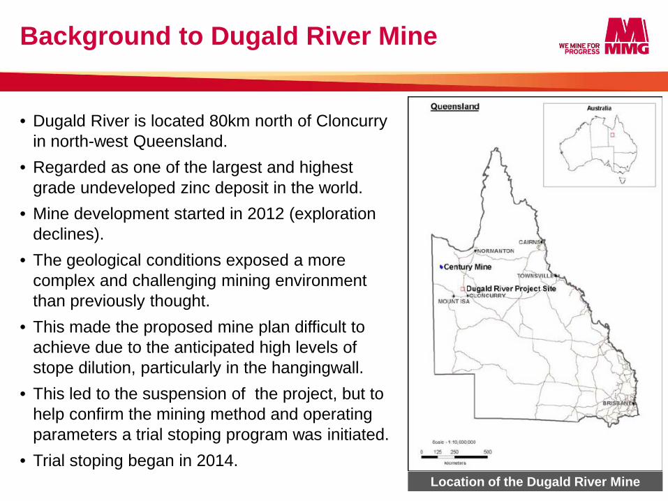
• Dugald River is located 80km north of Cloncurry in north-west Queensland.
• Regarded as one of the largest and highest grade undeveloped zinc deposit in the world.
• Mine development started in 2012 (exploration declines).
• The geological conditions exposed a more complex and challenging mining environment than previously thought.
• This made the proposed mine plan difficult to achieve due to the anticipated high levels of stope dilution, particularly in the hangingwall.
• This led to the suspension of the project, but to help confirm the mining method and operating parameters a trial stoping program was initiated.
• Trial stoping began in 2014.
Background to Dugald River Mine
2 Location of the Dugald River Mine
Trial Stoping
3
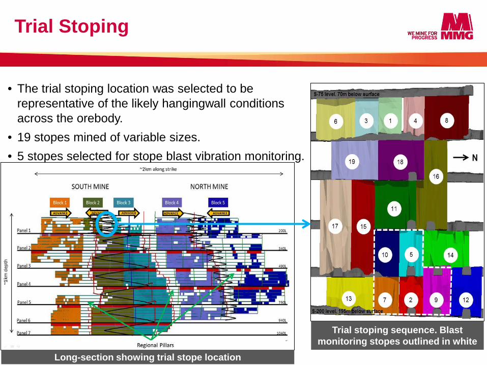
• The trial stoping location was selected to be representative of the likely hangingwall conditions across the orebody.
• 19 stopes mined of variable sizes. • 5 stopes selected for stope blast vibration monitoring.
Long-section showing trial stope location
Trial stoping sequence. Blast monitoring stopes outlined in white
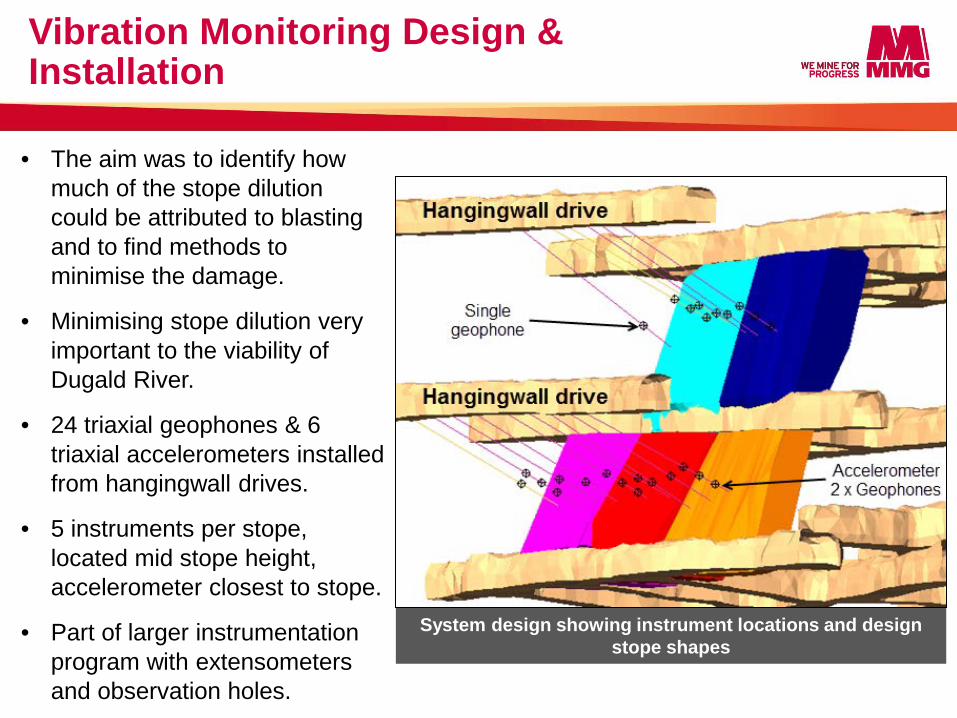
• The aim was to identify how much of the stope dilution could be attributed to blasting and to find methods to minimise the damage.
• Minimising stope dilution very important to the viability of Dugald River.
• 24 triaxial geophones & 6 triaxial accelerometers installed from hangingwall drives.
• 5 instruments per stope, located mid stope height, accelerometer closest to stope.
• Part of larger instrumentation program with extensometers and observation holes.
Vibration Monitoring Design & Installation
System design showing instrument locations and design stope shapes
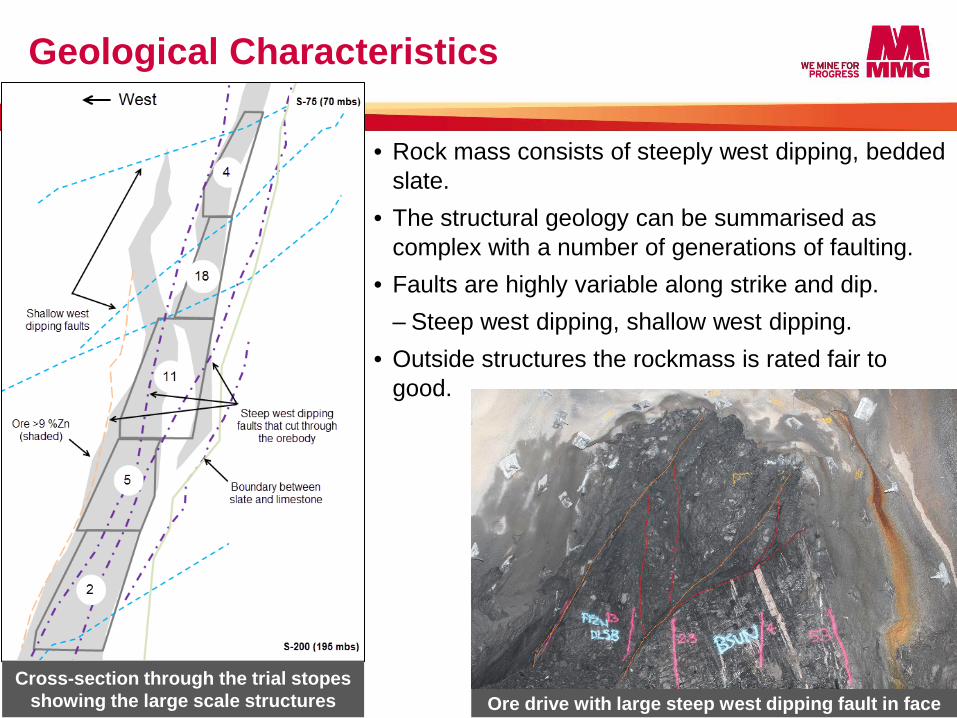
• Rock mass consists of steeply west dipping, bedded slate.
• The structural geology can be summarised as complex with a number of generations of faulting.
• Faults are highly variable along strike and dip. ‒ Steep west dipping, shallow west dipping.
• Outside structures the rockmass is rated fair to good.
Geological Characteristics
5
Cross-section through the trial stopes showing the large scale structures Ore drive with large steep west dipping fault in face
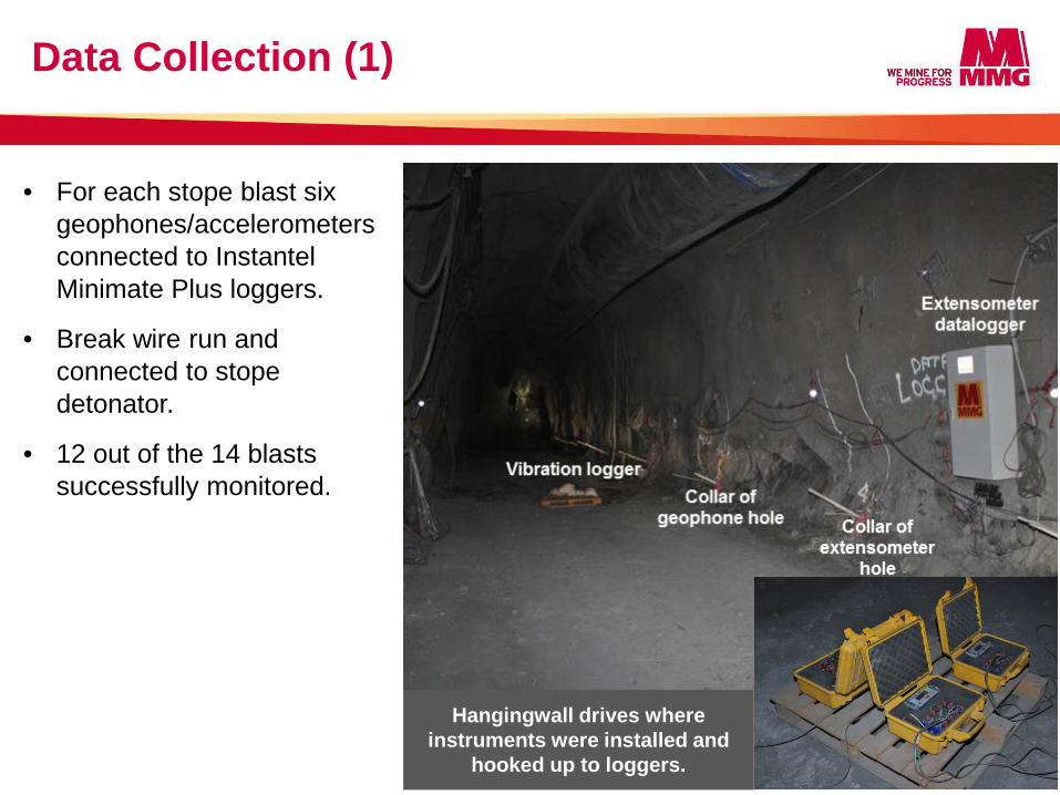
• For each stope blast six geophones/accelerometers connected to Instantel Minimate Plus loggers.
• Break wire run and connected to stope detonator.
• 12 out of the 14 blasts successfully monitored.
Data Collection (1)
6
Hangingwall drives where instruments were installed and
hooked up to loggers.
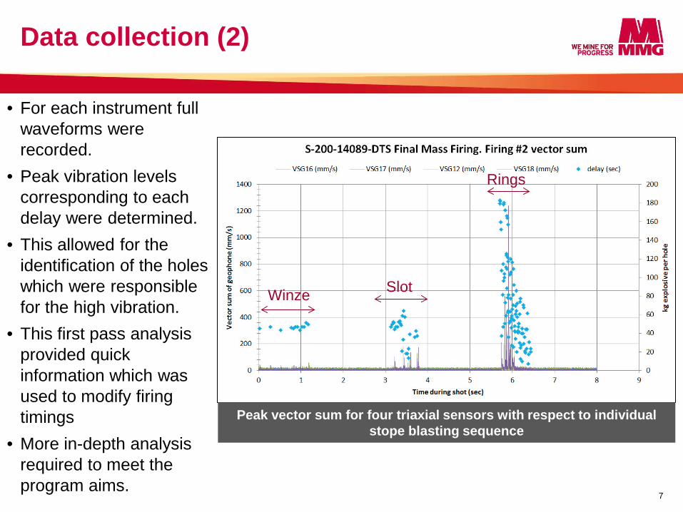
• For each instrument full waveforms were recorded.
• Peak vibration levels corresponding to each delay were determined.
• This allowed for the identification of the holes which were responsible for the high vibration.
• This first pass analysis provided quick information which was used to modify firing timings
• More in-depth analysis required to meet the program aims.
Data collection (2)
7
Peak vector sum for four triaxial sensors with respect to individual stope blasting sequence
Winze Slot
Rings
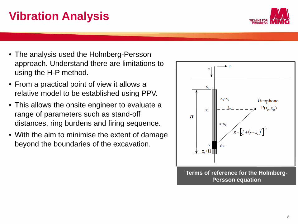
• The analysis used the Holmberg-Persson approach. Understand there are limitations to using the H-P method.
• From a practical point of view it allows a relative model to be established using PPV.
• This allows the onsite engineer to evaluate a range of parameters such as stand-off distances, ring burdens and firing sequence.
• With the aim to minimise the extent of damage beyond the boundaries of the excavation.
Vibration Analysis
8
Terms of reference for the Holmberg-Persson equation
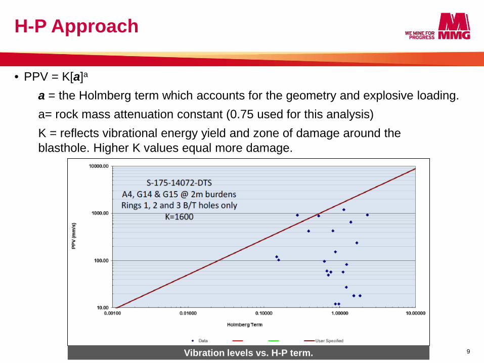
• PPV = K[a]a
a = the Holmberg term which accounts for the geometry and explosive loading. a= rock mass attenuation constant (0.75 used for this analysis) K = reflects vibrational energy yield and zone of damage around the blasthole. Higher K values equal more damage.
H-P Approach
9 Vibration levels vs. H-P term.
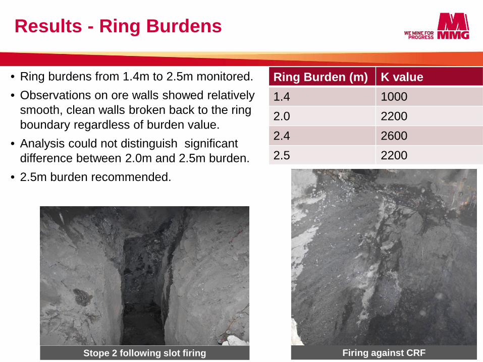
• Ring burdens from 1.4m to 2.5m monitored. • Observations on ore walls showed relatively
smooth, clean walls broken back to the ring boundary regardless of burden value.
• Analysis could not distinguish significant difference between 2.0m and 2.5m burden.
• 2.5m burden recommended.
Results - Ring Burdens
10 Stope 2 following slot firing Firing against CRF
Ring Burden (m) K value 1.4 1000 2.0 2200 2.4 2600 2.5 2200
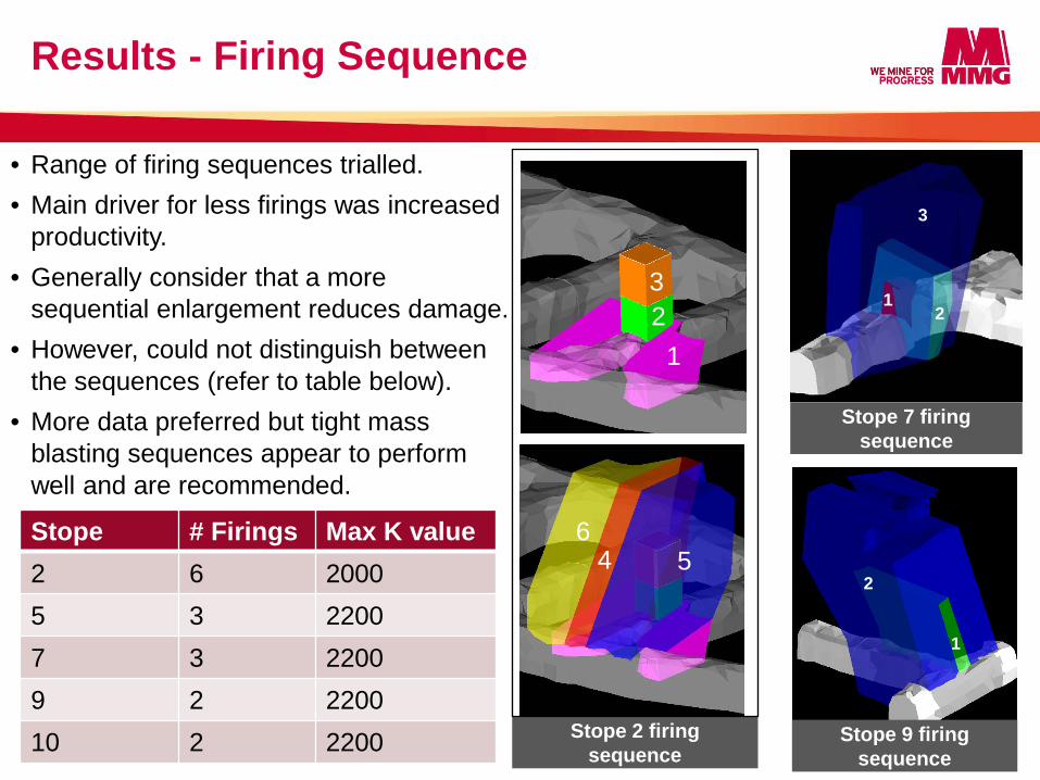
Stope # Firings Max K value 2 6 2000 5 3 2200 7 3 2200 9 2 2200 10 2 2200
Results - Firing Sequence
11
Stope 7 firing sequence
1 2 3
4 5 6
1
2
1 2
3
Stope 9 firing sequence
Stope 2 firing sequence
• Range of firing sequences trialled. • Main driver for less firings was increased
productivity. • Generally consider that a more
sequential enlargement reduces damage. • However, could not distinguish between
the sequences (refer to table below). • More data preferred but tight mass
blasting sequences appear to perform well and are recommended.
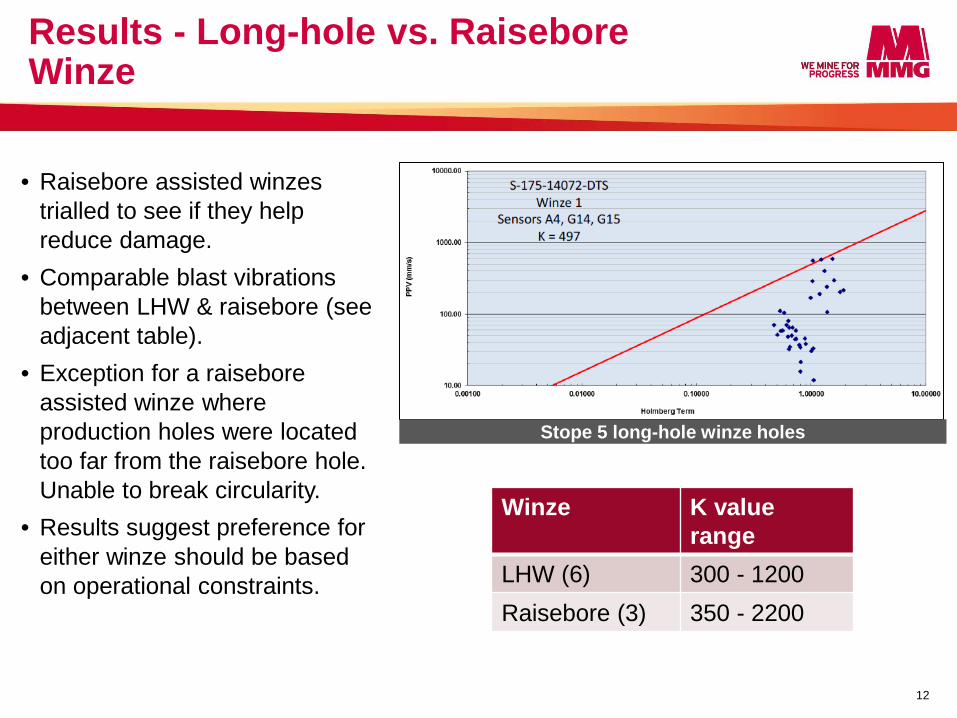
• Raisebore assisted winzes trialled to see if they help reduce damage.
• Comparable blast vibrations between LHW & raisebore (see adjacent table).
• Exception for a raisebore assisted winze where production holes were located too far from the raisebore hole. Unable to break circularity.
• Results suggest preference for either winze should be based on operational constraints.
Results - Long-hole vs. Raisebore Winze
12
Stope 5 long-hole winze holes
Winze K value range
LHW (6) 300 - 1200 Raisebore (3) 350 - 2200
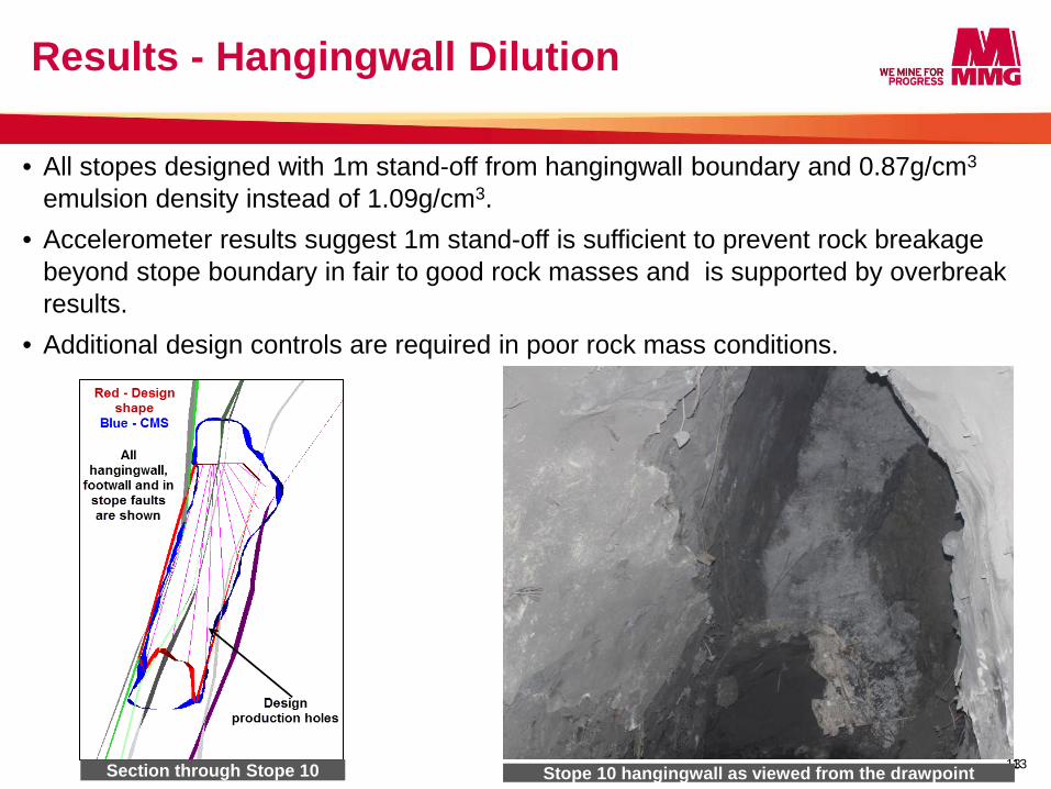
• All stopes designed with 1m stand-off from hangingwall boundary and 0.87g/cm3 emulsion density instead of 1.09g/cm3.
• Accelerometer results suggest 1m stand-off is sufficient to prevent rock breakage beyond stope boundary in fair to good rock masses and is supported by overbreak results.
• Additional design controls are required in poor rock mass conditions.
Results - Hangingwall Dilution
13 Section through Stope 10 13 Stope 10 hangingwall as viewed from the drawpoint
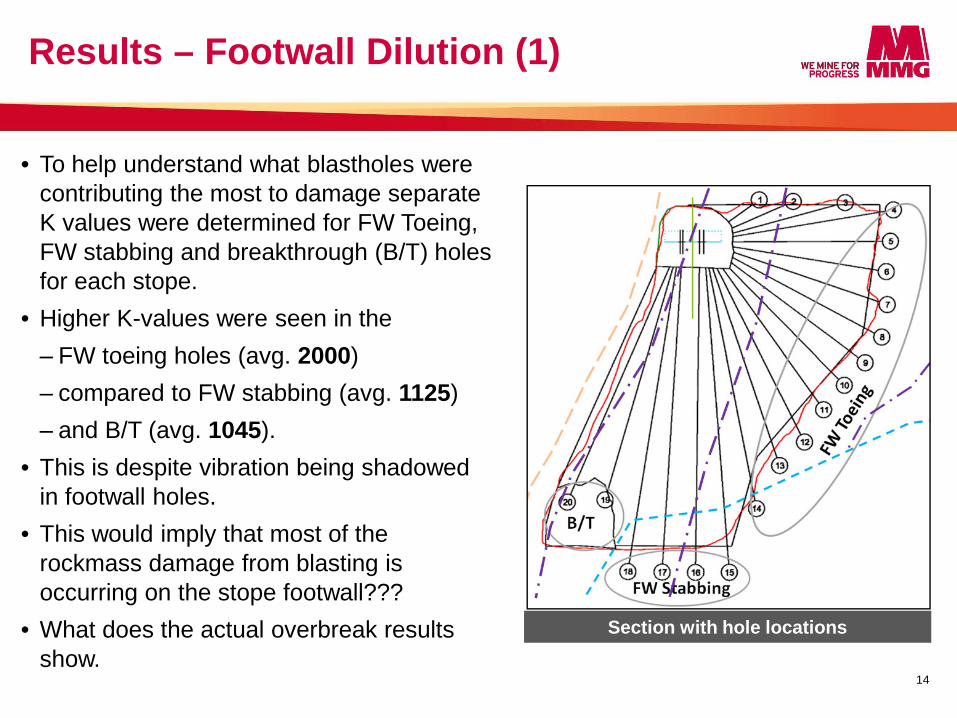
• To help understand what blastholes were contributing the most to damage separate K values were determined for FW Toeing, FW stabbing and breakthrough (B/T) holes for each stope.
• Higher K-values were seen in the ‒ FW toeing holes (avg. 2000) ‒ compared to FW stabbing (avg. 1125) ‒ and B/T (avg. 1045).
• This is despite vibration being shadowed in footwall holes.
• This would imply that most of the rockmass damage from blasting is occurring on the stope footwall???
• What does the actual overbreak results show.
Results – Footwall Dilution (1)
14
Section with hole locations
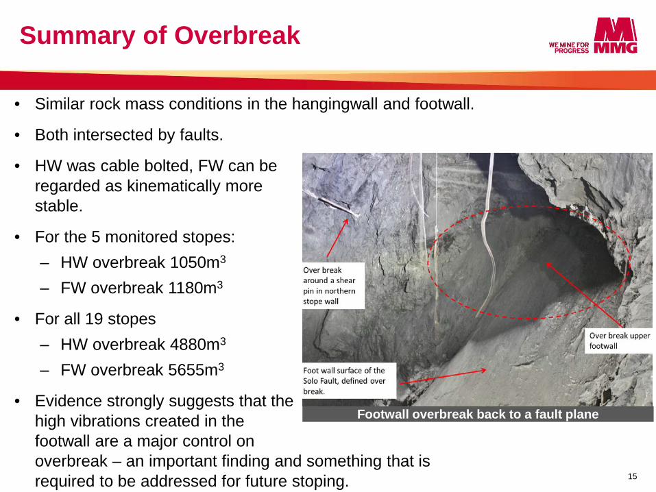
• Similar rock mass conditions in the hangingwall and footwall.
• Both intersected by faults.
• HW was cable bolted, FW can be regarded as kinematically more stable.
• For the 5 monitored stopes: ‒ HW overbreak 1050m3 ‒ FW overbreak 1180m3
• For all 19 stopes ‒ HW overbreak 4880m3 ‒ FW overbreak 5655m3
• Evidence strongly suggests that the high vibrations created in the footwall are a major control on overbreak – an important finding and something that is required to be addressed for future stoping.
Summary of Overbreak
15
Footwall overbreak back to a fault plane
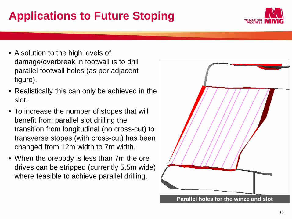
• A solution to the high levels of damage/overbreak in footwall is to drill parallel footwall holes (as per adjacent figure).
• Realistically this can only be achieved in the slot.
• To increase the number of stopes that will benefit from parallel slot drilling the transition from longitudinal (no cross-cut) to transverse stopes (with cross-cut) has been changed from 12m width to 7m width.
• When the orebody is less than 7m the ore drives can be stripped (currently 5.5m wide) where feasible to achieve parallel drilling.
Applications to Future Stoping
16
Parallel holes for the winze and slot
• Results suggest the current hangingwall stand-off distances, larger ring burdens and tight firings do not increase the overall damage to the rock mass. This has significant productivity outcomes compared to alternatives.
• Practical solutions were developed for the footwall dilution.
• Overall the blast vibration monitoring program can be regarded as successful.
What made it a success? • Clear objectives. • Strong management support and funding. • A high level of oversight. • Detailed analysis techniques. This could not have been achieved without the external assistance of Professor Ernesto Villaescusa, Dr John Heilig and Dr John Player.
Conclusions
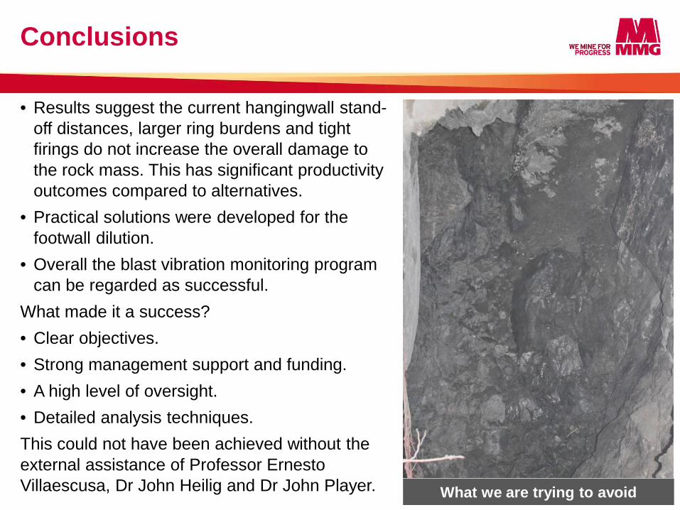
17 What we are trying to avoid
Thankyou & Questions?
18