Embed Size (px)
Citation preview

NASA TECHNICAL NOTE NASA TN 0-7666
flTASA-TN-D-7666) LANDING BATES FOR MIXEDSTOL AND CIOI T8AFFIC (HASA) 76 p HC$4.00. . - CSCL 17G ~
N7a-2129"0
UnclasHI/21 36622
LANDING RATES FOR MIXEDSTOL AND CTOL TRAFFIC
by John S. White
Ames Research CenterMoffett Field, Calif. 94035
NATIONAL AERONAUTICS AND SPACE ADMINISTRATION • WASHINGTON, D. C. . APRIL 1974
https://ntrs.nasa.gov/search.jsp?R=19740013177 2018-07-07T04:22:17+00:00Z

1. Report No.
D- 7666
2. Government Accession No. 3. Recipient's Catalog No.
4. Title and Subtitle
LANDING RATES FOR MIXED STOL AND CTOL TRAFFIC
5. Report DateAPRIL
6. Performing Organization Code
7. Author(s)
John S. White
8. Performing Organization Report No.
A-5044
9. Performing Organization Name and Address
NASA Ames Research CenterMoffett Field, Calif. 94035
10. Work Unit No.
501-03-11
11. Contract or Grant No.
12. Sponsoring Agency Name and Address
National Aeronautics and Space AdministrationWashington, D. C. 20546
13. Type of Report and Period Covered
Technical Note
14. Sponsoring Agency Code
15. Supplementary Notes
16. Abstract
A study was made to determine the expected landing rate for STOL-onlytraffic and mixed STOL-CTOL traffic. The conditions used vary from presentday standards to an optimistic estimate of possible 1985 conditions. Acomputer program was used to determine the maximum landing rate for thespecified conditions and aircraft mix. The results show that the additionof STOL on a CTOL runway increases the total landing rate if the STOL airbornespacing can be reduced by use of improved navigation equipment. Further, ifboth takeoff and landings are performed on the same runway, the addition ofSTOL traffic will allow an increase in the total operation rate, even withexisting spacing requirements.
17. Key Words (Suggested by Author(s))
Air Traffic ControlTerminal Area GuidanceAircraft Operations
18. Distribution Statement
Unclassified — Unlimited
CAT. 21
19. Security Classif. (of this report)
Unclassified
20. Security Classif. (of this page)
Unclassified
21. No. of Pages
76
22. Price*
$4.00
* For sale by the National Technical Information Service, Springfield, Virginia 22151

TABLE OF CONTENTS
PageNOTATION vSUMMARY 1INTRODUCTION 1THEORY OF LANDING-RATE CALCULATIONS 3Airborne Spacing 3Runway Clearance 6Probability of Abort 8Landing Rate 8Total Operation Rate 9
COMPUTER PROGRAM : 9PROGRAM INPUTS 10RESULTS 12Single-Velocity Approach 14Dual-Velocity Approach 17
CONCLUSIONS 20APPENDIX A - DERIVATION OF EQUATIONS FOR T12
22
APPENDIX B - PROGRAM LISTING AND DESCRIPTION 48REFERENCES 70
Pfci&EDING PAGE BLANK NOT FILMS*
A-5044 iii

NOTATION
Fortran Name Symbol
ACC
DA
SIG
M or ZM
RD. . .
<*>
SF
SO
T2ACT
To
TNOM
TTO
TVF
T12A
T12M(I,J)
VA or VB
a
K
m
N12
r(-)
S
Sf
So
La
Lact
2V,
ma
m
~nom
'to
V
'act
nom
V
aircraft acceleration capability, m/sec2
distance from runway threshold at which velocity ischanged, km
constant used to calculate AT
distance from runway threshold to outer marker, km
number of takeoffs between successive landings
range or expected variation of stochastic quantity
required separation distance, km
required separation at touchdown, km
required separation at outer marker, km
time, sec
average time between landings, sec
time before touchdown at which velocity is changed,sec
actual time from outer marker to touchdown, sec
runway clearance time, sec
time when xi = m2, sec
time when x = m, sec
nominal time from outer marker to touchdown, sec
time required for takeoff, sec
time at which aircraft must be at final velocity, sec
actual interarrival time, sec
nominal interarrival time, sec
aircraft velocity, m/sec
PRECEDING PAGE BLANK NOT FILMED

DELP
DELT 1DELT 2
DEL. . .'
TDL 1: TDL 2
ZLR
ZNOPR
TDEL
TFIN
TIN
TOED
x
x
&T
t\T
o
T ~.•jin
T .
med
aircraft location, km '
location of separation boundary, km
error in position at time of nominal passage overouter marker, km
landing time deviation, sec
error in ( )
allowance for errors in landing time, sec
landing rate, aircraft/hr
operation rate (landings plus takeoffs), aircraft/hr
generalized erroras-
interarrival time required for runway clearance, sec
interarrival time required for airborne spacing attouchdown, sec
interarrival time required for airborne spacing atmerge point, sec
interarrival time required for airborne spacing atvelocity change point, sec
Subscripts
1,2 refers to first or second aircraft in the landingsequence
VI

LANDING RATES FOR MIXED STOL AND .CTOL TRAFFIC
John S. White
Ames Research Center
SUMMARY .:
A study was made to determine the expected landing rate for STOL-onlytraffic and mixed STOL-CTOL traffic. The conditions used vary from presentday standards to an optimistic estimate of .possible 1985 conditions. A com-puter program was used to determine the maximum landing rate for the specifiedconditions and aircraft mix. The results show that the addition of STOL ona CTOL runway increases the total landing rate if the STOL airborne spacingcan be reduced by use of. improved navigation equipment. Further, if bothtakeoff and landings are performed on the same runway, the addition of STOLtraffic will allow an increase in the total operation rate, even with existingspacing requirements.
INTRODUCTION
Numerous studies have been made to determine the landing rate of aircrafton a single runway. In one of the early studies, Blumstein (ref. 1) con-sidered a traffic mix of various commercial transports arriving at an airportand computed the landing rate, assuming that aircraft were always available atthe gate. Simpson (ref. 2) and Odoni (ref. 3) describe theoretical equationsfor landing rate, including the effects of terminal area operations beyond thegate, and assume that the aircraft arrivals have a Poisson distribution. Bothgive some numerical results, but for CTOL vehicles only. An additional studyby the National Bureau of Standards (ref. 4) used a different concept of land-ing capacity, which involved a facility serving sequential customers of vari-ous types. Again, however, the results presented are for CTOL vehicles only.The capacity of a STOL runway was considered by Rinker (ref. 5), but numericalresults were presented for only two cases.
The purpose of this report is to supply additional information for STOL-only runways and to consider the effect of mixed STOL-CTOL traffic. Althoughthe National Aviation System Plan (ref. 6) implies that STOL and CTOL trafficwill use separate runways, there may be times when a common runway is requiredon a temporary basis. Thus this report develops a general theory of landingrates, which can be applied to separated or mixed traffic, and from whichexpected landing rates can be determined. Further, it indicates the accura-cies in control and navigation required to achieve various levels of landingrates. Finally, previous studies have assumed that all aircraft fly at con-stant airspeed all the way from the instrument landing system (ILS) gate totouchdown, a distance of 6 to 10 miles. An alternate approach is for an air-craft to fly at 160 to 180 knots at the ILS gate and then reduce speed gradu-ally to the final touchdown speed. The effect of such a speed change on thelanding rate is also considered.

The general approach used here parallels that of Blumstein, but it isconsiderably more complex to account for the variable speed approach and dif-ferent outer markers for CTOL and STOL. Also, Blumstein had only two separa-tion criteria — airborne spacing at the outer marker and runway clearance.This study adds another criterion: adequate airborne spacing must be main-tained until touchdown.
In this study, it is assumed that landings have priority, and that theaircraft land on a "first come, first serve" basis. We are concerned withmaximum capacity, and assume that the aircraft are immediately available tostart a landing approach whenever desired. This approximates the situationin which a good 4-D guidance system controls the aircraft in the terminal areato arrive within a few seconds of the desired time. If these arrival errorsbecome large, they will approach a Poisson distribution, and the landingcapacity will be reduced.
Takeoffs are also considered, but only when the sequence of landings issuch that a takeoff can be inserted without affecting the landing rate.
Sketch (a) shows some possible approach paths. The various CTOLapproaches merge fairly far out at the CTOL merge point, while STOL vehiclesmake curved approaches and arrive on the runway centerline at the STOL mergepoint.
The results of this study indicate the effect on airport capacity ofvarying the separation requirements and navigation accuracy. To fully utilize
the increased runway capacity sug-gested herein will probably require agreat deal of additional automation,both on the ground and in the air.This automation will probably not beavailable before about 1985. Further,in determining the actual separationcriteria, additional factors, such astrailing vortices, pilot and control-ler reaction times, accuracy of AirTraffic Control (ATC) surveillanceradars must be considered. However,the optimistic viewpoint taken heredoes provide useful information toaid in the determination of desirable
Possible STOLapproach paths
CTOL merge point
\ STOL merge point
Runway
Sketch (a)
trends in separation requirements, andindicates what portion of the approachsystem is presently acting as thelimiting factor.
The remainder of this reportfirst develops the theory of landing-rate calculations, then briefly

describes a computer program to solve these equations, and presents theinputs and results obtained.
THEORY OF LANDING-RATE CALCULATIONS
To determine landing rates, some of the characteristics of a single air-craft approaching the runway are first considered, then a technique is devel-oped for determining the minimum spacing between successive aircraft, and,finally, the maximum landing rate associated with a specific mix of aircraftis determined.
Airborne Spacing
The approach conditions for asingle aircraft are shown in figure 1.The figure is a plot of distance fromtouchdown versus time and shows theaircraft initially at its approachvelocity Va. The aircraft will con-tinue at this velocity for a while,and then it will decelerate at amaximum rate a to the final velocityVfo. The aircraft must reach thefinal velocity at time Tvf beforetouchdown so that the pilot cajn besure ~that~concli"trqns have stab]ili-zed before touchaowif. ~Tfie aircraft
Figure 1.— Definition ofapproach quantities.
continues at velocity ¥£, touches down at time t = 0, and rolls down therunway, and clears the runway kt time To after touchdown. The merge pointmay occur anywhere along this velocity time profile; two possible locationsare shown in the figure.
To simplify the equations associated with changing velocities, it wasassumed that the aircraft would fly at constant speed Va until it was a dis-tance Da from the end of the runway, at which time it would instantaneouslychange velocity to V ,. This step change in velocity simplifies the calcula-tion and, for reasonable values of separation, decreases the separation byless than 10 percent.
To determine Da, first locate the time Ta at which the two constant-velocity segments intersect, that is, Ta = Tvf + (Va - Fj,)/2a. Since
V

The location of the aircraft, x, at any time t is specified by
x =
x <. D.a(2)
which-can be solved for the time the aircraft is over the merge point:
T =m
m
b
aIT } > m > Da
(3)
Consider two aircraft approaching a given runway in sequence. A minimumseparation distance is required between the two aircraft at all times duringthe approach and, further, the second aircraft must not touch down until thefirst aircraft is off the runway. The problem is to determine the minimumtime between touchdowns that meets the separation criteria and, from this, todetermine the maximum landing rate. The two aircraft may be of differenttypes, with different approach paths, velocities, time-to-clear runway, sep-aration distances, etc. The separation requirements are stated in terms ofin-trail distances and must be met only while the two aircraft are on acommon path; before that, the vehicles are considered to have satisfactorylateral separation. - ,-.-_.-
A few terms should be defined more explicitly.. ..First, the merge pointis that point where the aircraft arrives on the extended^runway centerline, .and is. stabilized on the runway heading. The location.-,rof the merge .point, m,..varies from one type of aircraft to another. The common path is the section,of the flight path that will be used by two successive aircraft; therefore, .-it occurs between the minimum of mi and m2 and the runway and its lengthdepends on the types of the two aircraft. . . ; . - . . •
The separation requirements are defined so that, while- the first aircraftis on the common path, the second.aircraft must be far. enough behind. Thepresent-day separation requirement during approach is 6^km (~3 miles). Sincethe navigation systems of STOL vehicles may be more accurate, we wish to con-sider the possibility of reduced distance separations at the merge point, andalso a smaller separation requirement at touchdown than at the merge point.
Separation is defined as that portion of airspace reserved for a givenaircraft and is assumed to be half before and half behind the nominal air-craft position. The separation criterion for two aircraft is shown in

Reserved oirspoceA/C I
Reserved oirspoceA/C 2
figure 2, and the requirement isthat the reserved airspaces do notoverlap, or
x{ = xi + Si/2 < x2 = x2 - S2/2
(4)Figure 2.— Separation criteria,
where Si and S2, the separationdistances associated with eachaircraft, need not be constant with time. For this study, define a separa-tion requirement, So;, at the merge point, and Sj , at touchdown, and assumethat it varies linearly between those two points, that is,
for x . < m .^ ~~
x. > m.^ ^
(5)
This form for i = 1,2 was chosen toallow for a possible reduction inspacing as the aircraft approachesthe threshold while maintaining rel-atively simple equations.
To visualize the separationrequirement, figure 3(a) shows aspecific example of two approachingaircraft. For each aircraft, itsmerge point and velocity changepoint are shown. To guarantee sep-aration at all times, checks must bemade at three places, namely, at theend of the common path, at the begin- ——ning, and at the point where the.velocity of aircraft 2 changes. Inthe example shown, these tests occurat t = 0, t = 2V (since the commonpath starts at tne closest mergepoint, mi, as drawn), and at t = Ta .At these points, we want to guarantee that
Distoncefromtouchdown
Time
(a) Generalized situation.
Figure 3.— Separation betweensuccessive aircraft.
-TT-I > 0 (6)
For different types of approaching aircraft, the relative locations ofm-i. m?, D , and D , vary, as does the time of the tests, resulting in a
a\ 0.2variety of situations, each of which must be considered individually.A-5044 • - 5

To determine the closest possible spacing, three interarrival times arecalculated by selecting x2, in inequality (6), so that the difference is zeroat each of the three test times. The largest of these times guarantees ade-quate separation throughout the airborne portion of the flight. The effect
of runway clearance requirements isconsidered in the next section.
Considering the example offigure 3 (a) again, first calculateifin> which assumes that minimum sep-aration occurs at t = 0. This isshown in figure 3 (b) , where the tra-jectory for aircraft 2 is movedcloser to that for aircraft 1, andthe minimum separation, (Si + $2)72,occurs at t = 0. Next, calculateT£n, which assumes minimum separa-tion at t = Tmi (fig. 3(c)). Finally,calculate ^rned> which assumes mini-mum separation at t = Ta^ (fig. 3(d)).For this example, the critical testis the calculation for T^vn> and aninterarrival time of T12
= Tf£n>guarantees adequate airborne separa-tion throughout the flight.
The various cases that -canoccur, depending on the locations, of
jJe scribed
(b) Minimum separation at t - 0.
(c) Minimum separation at t = T
(d) Minimum separation at t
Figure 3.- Concluded.
= T,
in appendix A, along with the equa-tions for calculating the various) T.
Runway Clearance
Having computed the T value thatguarantees satisfactory separationeverywhere on the flight path, wenow consider separation on therunway. The FAA rule is that a fol-lowing aircraft may not touch downuntil the preceding aircraft clearsthe runway. The time a given typeof aircraft needs on the runwaybefore turning off, To, is known,but, in scheduling aircraft arrivals,some time must be added to allow forthe possibility of a late landing ofthe first aircraft or an early land-ing of the second aircraft. Foursources of error in landing time are
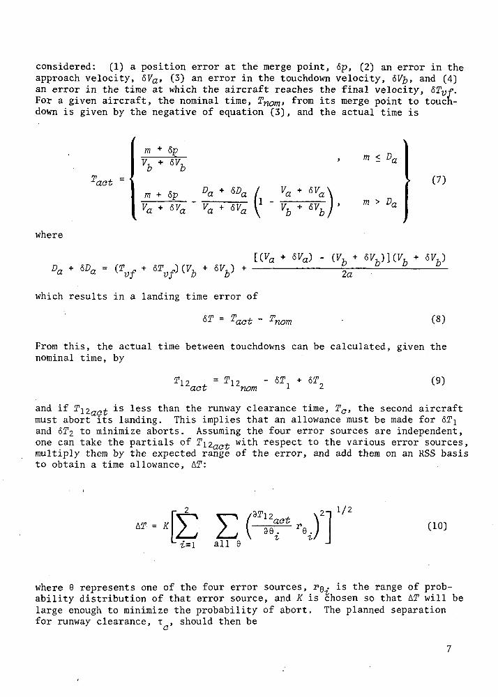
considered: (1) a position error at the merge point, 6p, (2) an error in theapproach velocity, 67a, (3) an error in the touchdown velocity, 67 , and (4)an error in the time at which the aircraft reaches the final velocity, <52yf.For a given aircraft, the nominal time, Tywm, from its merge point to touch-down is given by the negative of equation (3), and the actual time is
laat
where
mV
mva
Dava
1 -a
m
m > D,a
(7)
vf (7, 2a
which results in a landing time error of
(8)
From this, the actual time between touchdowns can be calculated, given thenominal time, by
"act= T12 - ST,
nom(9)
and if Ti2ao^ is less than the runway clearance time, Tc, the second aircraftmust abort its landing. This implies that an allowance must be made for &TIand 6^2 to minimize aborts. Assuming the four error sources are independent,one can take the partials of T\2ao+ with respect to the various error sources,multiply them by the expected range of the error, and add them on an RSS basisto obtain a time allowance, t\T:
A27 = K
i=l all
1/2
(10)
where 6 represents one of the four error sources, PQ. is the range of prob-ability distribution of that error source, and K is chosen so that AT will belarge enough to minimize the probability of abort. The planned separationfor runway clearance, T , should then be

TC = TO + AT
and the nominal interarrival time can be obtained from the various T valuesas ' .
where la ^ depends on the types of aircraft 1 and 2. (The equations forthe various partials used in equations (10) are given in appendix A.)
Probability of Abort
Since we are trying to maximize the number of aircraft to be landed, theaircraft will be flying close together, and if one separation criterion isviolated, the second aircraft should abort the landing. It is assumed thatairborne separation has been determined from a consideration of the likelyerrors in position and velocity of the aircraft; therefore, aborts due toviolation of the airborne separation will not occur (at least from theexpected errors) . However, the runway occupancy rule does not consider pos-sible errors; any violation of this rule will therefore cause an abort, asimplied by equation (9). The quantity AT (eq. (11)) is designed to considerthe effect of errors on the runway occupancy rule, and K (eq. (10)) is chosenso that the probability of abort because of a violation of the runway occu-pancy rule will be sufficiently small. As shown in appendix A, if K = 1, theprobability of abort is less than 0.006.
Landing Rate
To determine the average interarrival time T, calculate Ti2nom ^or a^possible sequences of aircraft types, and then obtain an average, weightedaccording to the relative probabilities of arrival associated with each typeof aircraft. It is assumed that there are n types of aircraft to be con-sidered, and the probability that the next aircraft is of type i is P£ and isindependent of the type of the previous aircraft. One then obtains
n nT = \^ Y^ P.P.T. . (13)
4- ^ V
where•i and j, and
obtained from equation (12), depends on the types of aircraftn
EP.-It—i ^
The nominal maximum landing rate, A , is then
Ar = 3600/T (14)LI

which assumes that aircraft are continually available to start their approachas soon as needed, and is thus a true measure of runway capacity. To achievethis capacity the terminal area controller must-be told when an aircraft-,should be at the outer marker, and a time-controlled guidance scheme, such assuggested by Erzberger and Pecsvaradi (ref. 7), must be available.
Total Operation Rate . .
Another factor of interest is the total operation rate, \o, of a runwaywhich allows takeoff s and landings to be mixed. To determine \o, consider aspecific interarrival time and determine if it is long enough to allow atakeoff to occur without delaying the landing of the second aircraft (there-fore, landings have priority over takeoff s) . Assume that the time for take-off T£O. is constant? for all aircraft, and that the types of aircraft 1. and 2are specified. We can determine the largest integer N^i that satisfies
which specifies that N\^ aircraft can take off in the available interarrivaltime.1 From the weighted sum of Nj,j over all types of aircraft, as inequation (13), and the landing rate, A£, the total operation rate, \o, isobtained: '
.^ )
*o = V, U + 2^ p / C16)
COMPUTER PROGRAM
A computer program was written to solve the various equations givenabove so that the landing rate and total operation rate could be determinedas a function of the various parameters of the system. The program is writ-ten in Fortran IV, and a brief description and listing are included inappendix B.
For each type of aircraft (the program handles up to 12 types), thefollowing input quantities are specified:
77? distance of the outer marker from runway threshold
So,Sf airspace required for separation at the outer marker and attouchdown
takeoff criterion is not strictly compatible with the present FAArequirements that specify 1 minute between successive takeoffs and 2 milesseparation between a takeoff and the following landing. However, it suggestshow arrivals can be interspersed with landings.

TQ runway clearance time
V<x>Vb approach velocity and touchdown velocity
T ,. time before touchdown when the aircraft should be at velocity V,
"' a [range of uncertainties of the various quantities
*«V*6VP probability of arrival of that aircraft type
The principal outputs were calculated from deterministic data using weightedaveraging techniques. These outputs were A.£, the landing rate, and \o, theoperations rate (calculated for T- o = 36 and 48 sec). Additional output wasobtained from Monte Carlo type runs in which 300 landings were made to deter-mine the number of landing aborts that occurred for a given set of conditions,For these runs, the random variables 6p, 67a, etc., were selected from a tri-angular distribution with the width equal to the corresponding range. Also,to control the number of aborts, the value K in equation (10) was variable.
PROGRAM INPUTS
To obtain average landing rates, the program referred to in the previoussection was used over a range of the various input parameters. The specificvalues used, along with a justification for the choice, are indicated in thissection. The parameters are the aircraft mix, and the quantities m, So, Sf,Tc> va> vb> ?vf> a> r&P> T&va> *&Vb> anci r&tvf selected separately for eachtype of aircraft.
For CTOL vehicles, two values of distance to the merge point, m, wereused — 19 km (=10 miles) and 7 km (,= 4 miles), which represent fairly longand fairly short approach paths presently in use. For STOL vehicles, 7 km(=4 miles) and 2 km (~1 mile) were used since it is unlikely that STOL vehi-cles will use the long approaches of the CTOL vehicles and, when a curvedapproach is used may turn onto the final heading fairly close to the runway.
The nominal values of separation, So, are 6 km (=3 miles) for CTOL vehi-cles and 2 km (»1 mile) for STOL vehicles. The CTOL separation is represen-tative of present standards, but STOL vehicles may have more precise naviga-tion and control systems so that reduced separations might be possible.
The airborne separation at touchdown, Sf, was usually set equal to So,the separation at the outer marker, but some runs were made with Sf essenti-ally zero. In this case, the actual separation at touchdown is held to rea-sonable values by both So and TQ. It is not clear whether present practiceis to have Sf = So, or to ignore it.
The runway clearance time was determined by computing braking time andadding to that an allowance for taxi time to the turn off. Braking time to
10

a dead stop, using 0.25 g deceleration, is roughly 30 sec for CTOL and 15 secfor STOL. The assumption of an additional 30 and 15 sec, respectively, fortaxi time gives the runway clearance time used, namely, 60 sec for CTOL vehi-cles and 30 sec for STOL. Data were also obtained for high-speed turnoffsthat are immediately available giving runway clearance times of 30 sec forCTOL and 15 sec for STOL.
Two different situations were assumed for the approach velocity. First,the aircraft is assumed to fly at touchdown velocity from its merge pointand, second, the aircraft is assumed to be at a velocity commanded by ATCwhen it passes its merge point, and to slow down during the approach. Thetouchdown speeds, F£, used were 60, 65, and 70 m/sec (=120, 130, and 140 knots)for CTOL and 30, 35, and 40 m/sec (-60, 70, and 80 knots) for STOL. It isfelt that these represent present-day CTOL touchdown speeds and proposed STOLtouchdown speeds. Also, it was assumed that, for the dual-velocity case, theinitial approach velocity, Va, was 90 m/sec (sl80 knots) for all CTOL vehiclesand 60 m/sec (=120 knots) for all STOL vehicles, which represent terminalarea cruise speeds.
In any case, a CTOL vehicle was required to reach its touchdown velocity1-1/2 min before touchdown and a STOL vehicle, 1 min before touchdown. Theseare felt to be the current requirements set forth by pilots, and were thevalues used for Tvf. The deceleration, a, used during the change of speed is0.6 m/sec2 (»0.06 g) for all vehicles.
As mentioned earlier, all random variables are assumed to be independentand to have a triangular distribution, centered about the nominal value, witha specified range. Thus, for a generalized random variable, 9:
6 - re/2 < 6 < 0 + re/2nom — act - nom
It is assumed that the pilot will maintain Velocity within ±1-1/4 m/sec(±2.5 knots) so that the range for both SVa and &V^ is r&Va= rSV^= 2,S m/sec.The position at the merge point is assumed to be ±1 km (±1/2 mile), r6p = 2 km,and the variation on Tvf is assumed to be r&Tvf = 30 sec for CTOL vehiclesand 10 sec for STOL vehicles.
A brief study of the actual mix of CTOL traffic at the San FranciscoAirport was the basis for the CTOL traffic mix used here. Three differentlanding speeds were assumed and their relative percentages are shown intable 1. The same percentages were used for STOL traffic. For mixed STOLand CTOL traffic, the percentage of aircraft with each landing speed is shownin table 1. The mix of aircraft shown is fairly representative and allresults presented here use this mix. Data were obtained for a mix with some-what higher average landing speed, which resulted in a slight increase inlanding rate, but the trends were not affected.
11

TABLE •!.- AIRCRAFT MIX FOR VARIOUS PERCENTAGES OF STOL TRAFFIC
Type
)STOL }
J
|CTOL }
J
\ STOL,
Land7 ^entspeed, m/sec \
303540
606570
0
000
453421
25
1195
342516
50
221711
221711
75
342516
1195
100
453421
000
RESULTS
The computer program was used with the input data just described for anumber of cases. The results are presented in a series of plots, following abrief discussion of the effects of some of the uncertainties.
The uncertainties in position and velocity affect the landing rate onlythrough the calculations to guarantee adequate spacing on the runway (air-borne spacing was controlled by the required separation). As a result,reducing these uncertainties had an effect very similar to reducing the timeon the. runway.
The nominal position uncertainty of 2 km at the merge point increasedthe required time spacing between touchdowns by between 15 and 30 sec,whereas each of the other uncertainties increased it by about 1 or 2 sec. Ifthese numbers are compared with the nominal runway occupancy time of 30 to60 sec, it is apparent that reducing the position uncertainty (or, equiva-lently, increasing the accuracy of time of arrival at the merge point) mightchange the landing rate significantly, but reducing the other uncertaintieswould have virtually no effect. Therefore, only the results for positionuncertainty are presented here.
The basic results are presented in figures 4 through 9 for single-velocitycases and in figures 10 through 15 for dual-velocity cases. In each figure,the landing rate is plotted against the percentage of STOL traffic. For sim-plicity, only two landing rate curves are shown which represent merge pointdistances of 19 km for CTOL and 7 km for STOL, and 7 km and 2 km, respec-tively. Other combinations of merge point distances fall between the curvesgiven.
The figures also show the total operation rate (sum of takeoffs andlandings) for takeoff times, T o, of 36 and 48 sec. These times approximateminimum and maximum takeoffs for CTOL jets-and, although a STOL vehicle could
12

150
IOO
take off in less time, it was felt that an allowance of less than 36 sec fortakeoff would be unrealistic. These curves are shown as bands in the figuresrather than as individual curvesbecause of the step-wise fashionin which takeoffs are added. Thisprocedure is explained in sketch (b).where landing and total operationrate are plotted versus separationfor two values of m. The conditionsfor sketch (b) are: two types ofSTOL vehicles, each using a. single-velocity approach, one at 40 m/secand the other at 30 m/sec, with50 percent probability of each type,T0 = 30, T-fo =36. As the landingrate decreases, because of anincrease in separation, the number
xunits/hr
50m = 7 km
m=2 km
2S0l. km
of takeoffs that can be insertedbetween landings increases in astep-wise fashion, one takeoff at a time.
Sketch (b)
These steps occur at differentvalues of So for m = 2 and m = 7 km, so that the total operation rate issometimes larger for one case and sometimes for the other. Other values ofm would cause the steps to change at other locations. As a result, it isvery difficult to determine the effect of m on the total operation rate and,as indicated previously, the total operation is shown as a band in figures 4through 15. One noticeable trend is that the total operation rate tends toincrease as the landing rate decreases.
Table 2 presents the values of the parameters used for each case. Sixcases are listed and each was run for both the single-velocity and dual-velocity approach.
TABLE 2.- DATA FOR EACH CASE . . . '.
Case
PresentNominalReduce runwaytime
Improve STOLnavigation
Minimal navi-gation errors
Minimal spacing
STOLSo, km
6 ;
2
2
2 •
2.1
CTOLS0, km
66
6
6
6.1
STOLT0, sec
3030
15
30
3030
CTOLT0, sec
6060
30
60
6060
STOLr6p, km
22
2
1
.1
.1
CTOLr6p, km
22
2
2
.1
.1
The present case used the current FAA rules for both STOL and CTOL. Forthe nominal case, since it is assumed that the STOL vehicles will use moreaccurate path guidance, the STOL spacing can be reduced to 2 km. Next is anominal case with the runway occupancy time cut in half, then the case for.
13

which the STOL navigation and guidance errors were reduced from the nominal.To show the maximum effect of these errors, they were essentially eliminatedfor both CTOL and STOL for the next case. For the final case, with the spac-ing and errors reduced to nearly zero, the aircraft are not allowed to passand must obey the runway occupancy rule, but otherwise they may be extremelyclose. Separation requirements for trailing vortices are not considered.
The results are now discussed, case by case, to show the changes to thelanding rate and total operation rate, as STOL traffic is added to existingCTOL traffic. Also, the factor that controls the landing rate will be
described, that is, whether the con-trolling factor is the airborne spac-ing at the merge point, at the touch-down point, or, for the dual-velocitycase, at the midpoint (where thevelocity changes), or whether it is
v,v;; the runway occupancy time.
90
80
70
so
"50
I
40
30 -
20 -
TTO=36 sec
TTO=48 sec
CTOL
STOL
60 sec30 sec
S0 = S,
6 km6 km
2 km2 km
Landings onlymCTOL ^ kmmSTOL 2 km
50STOL, percent
75 100
Figure 4.— Single velocity,present standards.
Single-Velocity Approach
Present standards— The situationusing present standards is shown infigure 4. As expected, .increasingthe percentage of STOL traffic reducesthe landing rate even when the mergepoint for CTOL and STOL traffic isfairly close in. Also, for fixedpercentages of STOL traffic, reducingmsTOL and WCTOL increases the landingrate. The factors that control thelanding rate are airborne spacing atthe merge point when the second air-craft is slower than the first andthe spacing at touchdown when thesecond aircraft is faster. In eithercase, the spacing is such that runwayoccupancy time does not affect thelanding rate.
When total operations are considered, the addition of STOL traffic mayallow an increase in the rate, assuming aircraft are waiting to take off,since there are more gaps in the arriving traffic which can be used fortakeoffs.
Nominal— The nominal case, with improved STOL navigation accuracy andtherefore reduced STOL separation, is shown in figure 5. Here, adding STOLtraffic decreases the landing rate only slightly and, with the higher percen-tages of STOL traffic, the landing rate actually increases. Also, an all-STOL runway has a higher landing rate than a CTOL runway. The controllingfactor is again the spacing at the merge point or at touchdown when the firstaircraft is STOL.
14

When total operations are considered, the addition of STOL vehiclesincreases the total operation rate.
Reduced runway time— Next consider the case with reduced time on therunway for both CTOL and STOL (fig• 6). Since the landing rate for CTOL vehi-cles is controlled by airborne spacing, reducing the runway time does notaffect the landing rate although it allows a considerable increase in thetotal operations. The landing rate for STOL vehicles was controlled by runwaytime so that the STOL landing rate increased considerably. A further reduc-tion in the runway time below 15 sec would increase landing rate only slightly.Again, for this case, introducing STOL vehicles to the traffic mix decreasesthe landing rate only slightly, with a considerable increase for larger per-centages of STOL. The trend is for increasing total operations as STOL air-craft are added to the mix.
100 ,-
9O
80
70
.c
I 60
<n
§
S 501o
40
30
20
NO
100
90
80
«70O)
^3
£oB 600)o.o
50
40
30
CTOLSTOL
60 sec30 sec
2 km2 km
CTOLSTOL
30 sec15 sec
6 km2 km
2 km2 km
Landings only
25 50STOL, percent
75 100 25 50STOL, percent
TTO = 36 sec
TTO = 48 sec
75 IOO
Figure 5.— Single velocitynominal case.
Figure 6.— Single velocity .reducedrunway time.
15
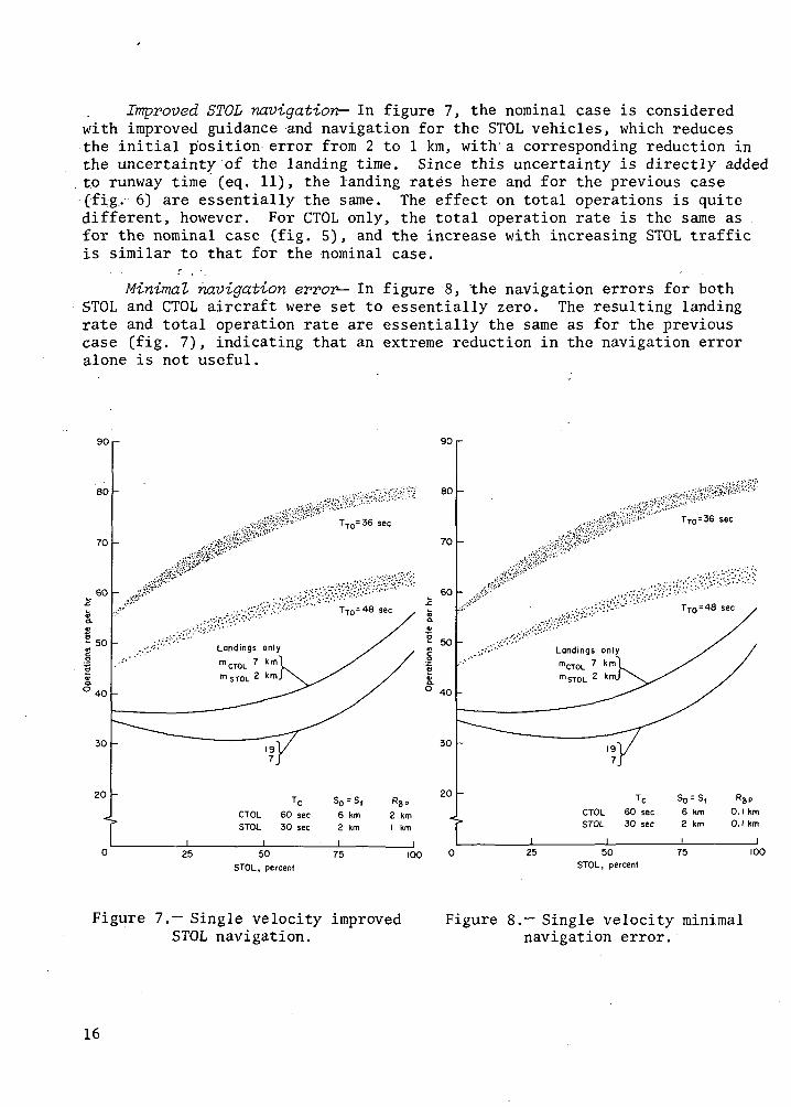
Improved STOL navigation— In figure 7, the nominal case is consideredwith improved guidance and navigation for the STOL vehicles, which reducesthe initial position error from 2 to 1 km, with a corresponding reduction inthe uncertainty of the landing time. Since this uncertainty is directly addedto runway time (eq. 11), the landing rates here and for the previous case(fig.- 6) are essentially the same. The effect on total operations is quitedifferent, however. For CTOL only, the total operation rate is the same asfor the nominal case (fig. 5), and the increase with increasing STOL trafficis similar to that for the nominal case.
Minimal navigation error— In figure 8, the navigation errors for bothSTOL and CTOL aircraft were set to essentially zero. The resulting landingrate and total operation rate are essentially the same as for the previouscase (fig. 7), indicating that an extreme reduction in the navigation erroralone is not useful.
90 r-
80
70
60
50
4O
30
20
TTn= 36 sec
90 r
80
70
50
40
30
20
CTOLSTOL
60 sec30 sec
6 Km2 km
"8P2 kmI km
TTO=36 sec
TTO = 48 sec
Landings onlymCTOLmSTOL
CTOLSTOL
60 sec30 sec
6 km2 km
O.I kmO.I km
25 50
STOL, percent75 IOO 25 50
STOL, percent75 100
Figure 7.— Single velocity improved Figure 8.— Single velocity minimalSTOL navigation. navigation error.
16

Minimal spaaing— Finally, consider the case (fig. 9) in which the spacingis reduced to correspond to the increased navigation accuracy. To determinethe extreme situation, a minimal spacing value of 0.1 km was used. With this.spacing, the landing rate is determined almost exclusively by the runway occu-pancy time and, to a lesser degree, by the error in touchdown velocity. Theaddition of STOL traffic increases the landing rate, and a- STOL-only runwayagain has a higher landing capacity than the CTOL-only runway. Moving theSTOL. merge point closer also increases the landing rate by decreasing theallowance required to compensate for the uncertainty in final velocity. Forthis case, times are available for only a few takeoffs, and then only withmixed traffic, when the distant merge points are used.
Dual-Velocity Approach . .
For a dual-velocity approach, all CTOL aircraft use the same constantspeed from the CTOL merge point until time to change velocity, about 5 or 6 kmfrom the threshold. As a result, the location of the merge point for CTOLvehicles has very little effect on the landing or takeoff rate; therefore, itis not shown as a parameter in the figures.
The landing rates and the total operation rates for the dual-velocityapproach are shown in figures 10 through 15.
IIOi-
100
90
80
S 70
0 60
50
40
25
Landings onlymCTOL =7 km~|mSTOL = 2 kmj
TTO = 48 sec
CTOLSTOL
TC60 sec30 sec
O.I kmO.I km
50STOL, percent
75
Figure 9.— Single velocityminimal spacing.
90,-
80
70
60
"SPO.I kmO.I km
I100
50
40
30
20
.>:'/'''''' TTO=48 sec
CTOL 60 secSTOL 30 sec
6 km6 km
2 kw
2 kw
25 50
STOL, percent75 100
Figure 10.— Dual velocitypresent standards.
17

Present standards— The results for this case are shown in figure. 10, andthe trends are generally the same as for the constant velocity approach.Adding STOL to the traffic mix reduces the landing rate but increases thetotal operation rate. The landing rate is controlled strictly by airbornespacing, usually at touchdown but, in some cases, at the velocity changepoint.
Nominal— The reduced spacing for STOL vehicles (fig. 11) now results ina strictly increasing landing rate as the proportion of STOL vehiclesincreases and in an increasing total operation rate. The controlling factoris the airborne spacing for a CTOL first aircraft and either airborne spacingor runway clearance, depending on «STOL» f°r a STOL first aircraft. The land-ing rate for this case is somewhat larger than for the corresponding single-velocity case (fig. 5), but the total operation rate is less.
Reduced runway time— When the runway occupancy time was reduced (fig. 12),the landing rate increased compared to the nominal (fig. 11), for W = 7 km,
no -
100 -
90 -
80
60Io
50
40
30
TcCTOL 6O secSTOL 30 sec
6 km2 km
R8P
2 km2 km
TTO = 36 sec
25 50STOL, percent
75
110
100
90
80
8. 70
60
5O
30
I100
TTn=36 sec
TTO = 48
Landings onlymSTOL 2 kml
CTOLSTOL
30 sec15 sec
S0 = S,6 km2 km
25 50
STOL, percent
75
kmkm
100
Figure 11.— Dual velocitynominal case.
Figure 12.— Dual velocity reducedrunway time.
18

where runway occupancy was the controlling factor, but otherwise was unaf-fected. The total operation rate, however, increased considerably compared tothe nominal. For this case, increasing the STOL traffic increased the landingrate and also increased the total operation rate.
Improved STOL navigation— Again, as in the single-velocity case, improv-ing the STOL navigation and guidance (fig. 13) had the same effect on thelanding rate as reducing the runway occupancy time (fig. 12). The totaloperation rate, however, is essentially the same as for. the nominal case(fig. 11). Both landing rate and total operation rate increase with increas-ing STOL traffic.
Minimal navigation errors— Further reductions in the navigation andguidance errors (fig. 14) had no effect on either the landing rate or thetotal operation rate.
90
80
70
5O
4O
30
20
TTO = 36 sec
25
Landings only
TC S0 = S ,
CTOL 60 sec 6 kmSTOL 30 sec 2 km
j i50
STOL, percent75
2 kmI km
90 •-
80
70
60
I
100
50
'40
30
20
25
TTO = 36 sec
All m
Landings only
CTOL 60 secSTOL 30 sec
6 km2 km
50STOL, percent
75
R8P
O.I km0. 1 km
100
Figure 13.— Dual velocity improvedSTOL navigation.
Figure114.— Dual velocity minimal; navigation errors.
19

IIOi-
100 -
Note: No time available for take-offs
Minimal spacing— Reducing thespacing to a minimal value (fig. 15),however, increased the landing ratedramatically over the nominal, butleft no time for takeoffs.
Comparison with single-velocitycase— Generally, the landing rate forthe dual-velocity case is somewhathigher than that for the correspond-ing single-velocity case. Thishigher landing rate tends to accom-pany a somewhat lower total opera-tion rate.
The trends for both the dual-velocity and single-velocity casesare very similar with changes inspacing, navigation, and runway occu-pancy time. However, as the percen-tage of STOL traffic increases, thelanding rate always increases in thedual-velocity case; in the single-velocity case, the landing rate firstdips and then increases.
50STOL, percent
100
based
CONCLUSIONSFigure 15.— Dual velocity
minimal spacing.The following conclusions are
on the philosophy that landings have priority over takeoffs.
Adding STOL traffic to a CTOL runway causes only a minimal decrease inthe landing rate for a constant-velocity approach, while for the dual-velocityapproach, there is an actual increase in the landing rate. This assumes thatthe STOL navigation is sufficiently better than existing CTOL navigation sothat the STOL spacing can be reduced from 6 to 2 km (3 to 1 mile)-. With thisspacing, the landing rate on a STOL-only runway will be greater than on exist-ing CTOL runways.
Under all circumstances, including the use of present standards, theaddition of STOL traffic to a CTOL runway will allow an increase in the totaloperation rate (i.e., landings plus takeoffs). Thus, with mixed STOL-CTOLoperations, there is frequently time for a takeoff without disturbing thelanding sequence so that mixing takeoffs and landings on the same runway isfeasible and perhaps desirable.
To increase landing rates (from present values), airborne spacing must bereduced, which, in turn, requires improvements in navigational accuracy.
20

Reducing runway occupancy time has little effect on the landing rate but doesallow for an increased total operation rate.
Generally, the landing rate is higher if the STOL merge point is as closeas possible to the runway threshold, thus taking maximum advantage of the STOLmaneuvering capability.
Ames Research Center -National Aeronautics and Space Administration
Moffett Field, Calif. 94035, October 29, 1973
21

APPENDIX A
DERIVATION OF EQUATIONS FOR
The kinematic equation of motion of an aircraft approaching the runwayis given by equation (2), assuming that the aircraft touches down at t = 0.This is true for the first aircraft, but the second aircraft touches down attime Ti2 after the first. The equations of motion for the two aircraft arethen:
(Al)
V* -
- J*- 12) .2 J
(A2)
From these equations, one can calculate the times when the aircraft areat specific points. These times, and their equations, are: the time the Ifirst aircraft is at its merge point, m^, , "
[.i. A-L 7 7 I V, I 'al al \ Z>i/
(A3)
the time the first aircraft is at the merge point for the second aircraft,
2" = 4ma
<-£„
Z?.a-
a. 7.
££•» \
"V '> Da
(A4)
22

and, finally, the time at which the second aircraft changes its speed,
Da
\ = T i 2 - T T (A5)D2
I , ;
The equation that defines the reserved airspace for the first aircraft isobtained by combining equations (4) and (5):
- S, Yi= xl
(A6)
where
I l ~ fl\
*1=\1+ 2BI! )
Note that since no tests are needed at times before the first aircraft arrivesat its merge point, Xi is not needed for x\ > m^. Similarly, the reservedairspace for the second aircraft is
2
o.
1 - X2 <
x2
•SfJ2 x2 < m2
where
S^ - S,
23
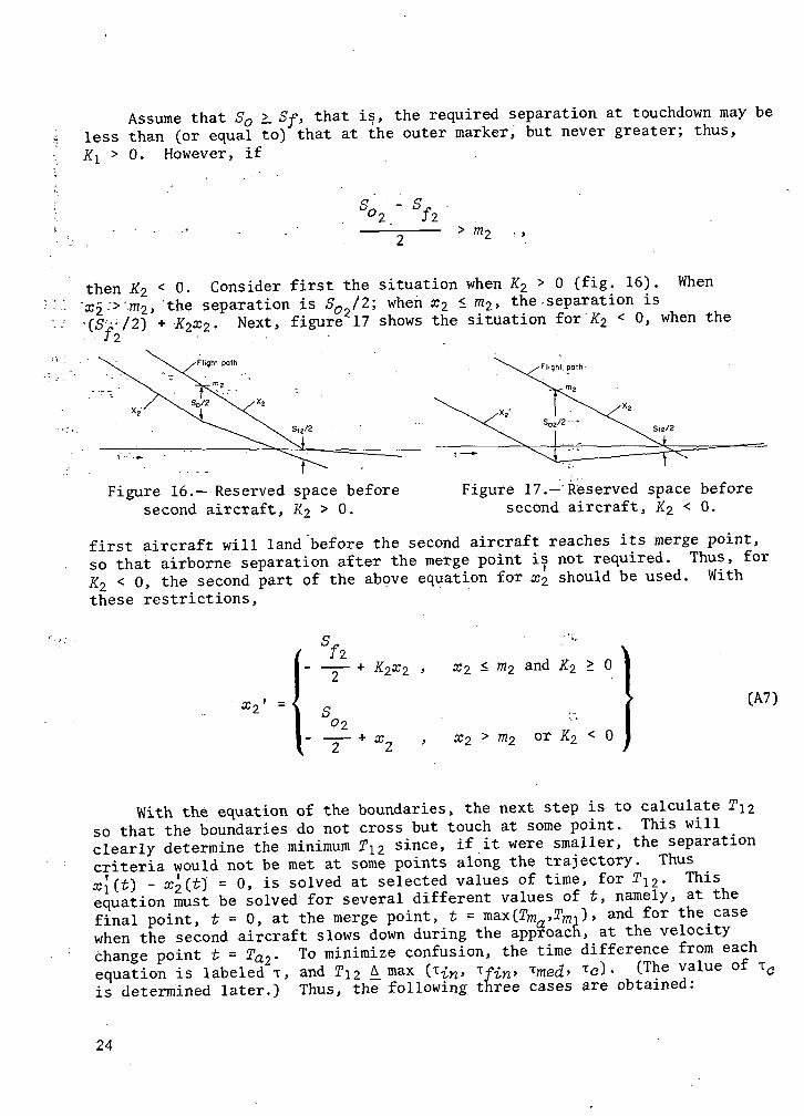
Assume that So >_ Sf, that is, the required separation at touchdown may beless than (or equal to) that at the outer marker, but never greater; thus,KI > 0. However, if
- s,ffl2
then K2 < 0. Consider first the situation when K2 > 0 (fig. 16). When•x2->--m2, the separation is So /2; when x2 < m2, the-separation is•(S T/2) + K2x2. Next, figure 17 shows the situation for K2 < 0, when the• • J2 •
Flight, path
Figure 16.— Reserved space beforesecond aircraft, K2 > 0.
Figure 17.—'Reserved space beforesecond aircraft, K2 < 0.
first aircraft will land before the second aircraft reaches its merge point,so that airborne separation after the merge point is not required. Thus, forK2 < 0, the second part of the above equation for x2 should be used. Withthese restrictions,
fa— + K2x2
02— + x
x2 < m2 and K2 > 0
x2 > m2 or K2 < 0
(A7)
With the equation of the boundaries, the next step is to calculate T\2so that the boundaries do not cross but touch at some point. This willclearly determine the minimum T12 since, if it were smaller, the separationcriteria would not be met at some points along the trajectory. Thusx\(f) - x2(f] = 0, is solved at selected values of time, for T12. Thisequation must be solved for several different values of t, namely, at thefinal point, t = 0, at the merge point, t = max(Tma,Tmi), and for the^casewhen the second aircraft slows down during the approach, at the velocitychange point t = Ta2- To minimize confusion, the time difference from eachequation is labeled T, and T\2 A^max (T W, if£n, imed>
Tc)• (The value ofis determined later.) Thus, the following three cases are obtained:
24

I:
IIA:
IIB:
III:
x](0) - a;2'(0) = 0 , solve for
x\ (21 ) ~ Xy' (T 1 = 0 , m? < ni ma L ma.
11 T \ •v i IT i — oXA a2) ~ 2 \ a2/" '
solve for T.n
< 0 , solve for T
(A8)
If the restriction :for case III test is not met, then a test for case IIIis not needed; for convenience, we set Tmg( = 0 so that it cannot be'1 selectedas the maximum in determining Ti2. To solve equation (A8) for T, use equa-tions (Al) through (A7). Since these are conditional equations, depending onthe relationships between #2(t), Da2, ro2, m^, etc., many subcases arise. Eachmust be solved for and then checked to ensure that all conditional relation-ships are met, and, finally, the defining conditions for each subcase must bedetermined in terms of the input quantities, m1} Da , So , S-P , Va , V-^ , and•i = 1,2. This procedure is followed for each subcase in the following sec-tions. A small sketch shows position versus time and indicates the locationof the input quantities for each subcase. . '. . . . .
CASE I
In this case, t = 0, so the following equations are needed
*i = 0 , (A9)
V TZ>2 12
+ V T"2 V 7, I a9 12 '
X2 <
- m2
^
(A10)
or
(All)
These equations lead to four subcases, each of which is considered separately.
25
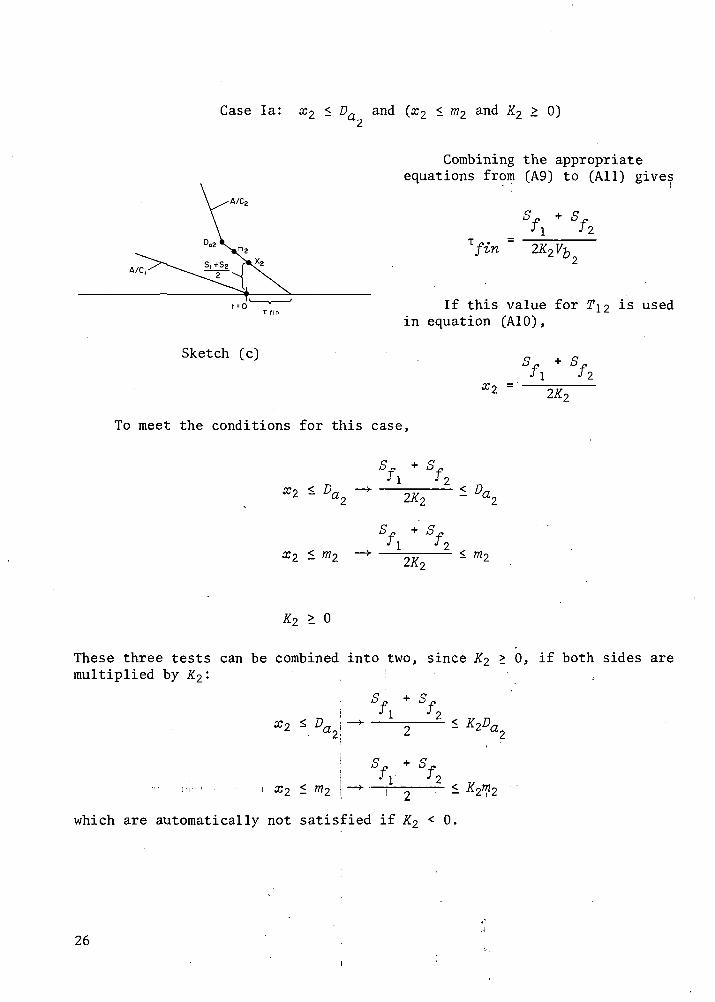
Case la: x2 < Da and (x2 < m2 and K2 > 0)
A/C,
t=0
Sketch (c)
Combining the appropriateequations from (A9) to (All) gives
J l
fin 2K2Vbr
I£ this value for T\2in equation (A10),
J 2
To meet the conditions for this case,
used
x2 < D
S + SJ ! 7 2
< m2
K2 > 0
These three tests can be combined into two, since K2 > 0, if both sides aremultiplied by K2:
!
Sf +SfJ ! J 2
11 • i 332 — ^2
which are automatically not satisfied if K2 < 0.
26
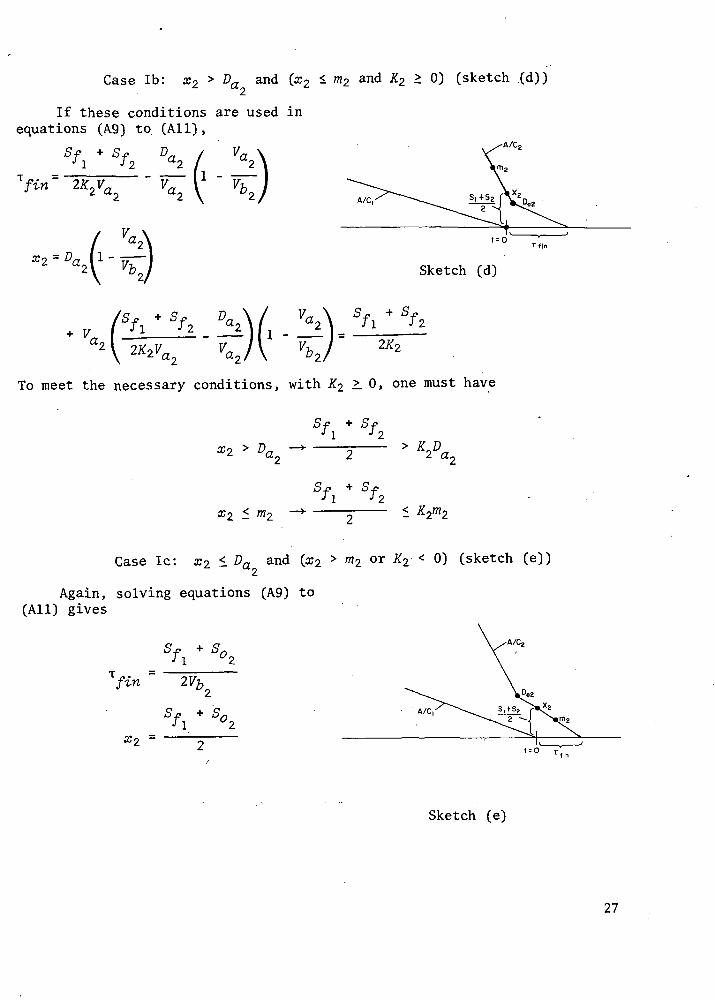
Case Ib: x2 > Da and (x2
If these conditions are used inequations (A9) to (All),
1 m2 and K2 > 0) (sketch (d))
T „. =fin 2K2Va^
Vn
Sketch (d)
sf + sTl /
2K2
To meet the necessary conditions, with X2 >. 0, one must have
+ Sf1 J2
2 a_
Case Ic: x2 1 Da and (a;2 > m2 or K2 < 0) (sketch (e))
Again, solving equations (A9) to(All) gives
A/C2
fin 2Vb
.Sketch (e)
27

The condition tests are
<7 4- QSfl S°2
*2 <- V - 2— 1 *
S + S
x2 >
Case Id: x2 > D and (3:2 > m2 or K2 < 0) (sketch (f))2
Sketch •(£)
The condition tests are
/*« 2-
F,a. S.
42 \ : ffe I 2Z j
42 \ "fc I 2
> DCtr
Sf +
J 1m2
Remarks ( '
Although all four cases have been discussed, the tests do not appear toguarantee that all possible conditions were included. However, if the valueof K2 is substituted into the second test for case la, one obtains
2 < 1 -J2
50 - Sf2 J 2
2m?
28

or
O .£» • O -£* O y-1 ™ jO .£* J^ -/? ^ & Stfl f2 o2 . f2 f1 o2
2 2 ~ 2 " m*
cases Ic and Id, thus showing that . 2 -^2^2all possible conditions were included.
No
Figure 18 is a flow chart of the case S||+S'2 <K, D, S | | + S°2<D
is that described under cases la and i° .- tn> ^ ™-r-i S||+S(2 S t i+Sfa D02 / V0?\iD- T"" 2K2Vb 2
T"n 2K2 Vo2 Vo2 ^ Vt,2/S(l + So2
T"" 2Vb2
TASF. TTA " 'S,, + S02 1 V 0 2 \ ] . .
2 D°' \ Vbzjj'^
;M Figure 18.— Calculation of T,,. ..Here, the minimum separation is .. . - J^n-
determined when the'T first aircraft isat the merge point. The merge pointis assumed to be m^, so that x^ = m-^, ^2 - m\ anc^ ^needed obtained from equations (Al) to (A7), are "a equations
(A12)
(A13)
(A14)
Note that only one Equation for x2 is needed here since x2 > x± = m2: Further,since K2 does not enter the equation, its value need not be considered.
ma
^/,m2r«,
1
"-!
*"«,
/, ^>v • •*.
, • ' arj = m2 < Dal
, xi = m2
(A15)
29:-

For each of the four cases here, solve equations (A12) to (A15) for T12 = Tin-
The solutions and the required tests are as follows:
Case IIAa: x\ < Da , x2 < Da (sketch (g))
Note: en | shown < D0|, but moy be > Da,
Sketch (g)
n
A/C
Case IIAb:
Note: mi shown < Oah but may be > D0|
D02 shown <mg, but may be>m2
Sketch (h)
< Da , x2 > Da (sketch (h))
so Da°2 "2V.0.
in 2Vf1 -
C2 a2
7
Case IIAc: Xi > Da , x2 < Da (sketch (i))
T . =27,
2 ^2
ll / Val+ ^ll-
Sketch (i)
30
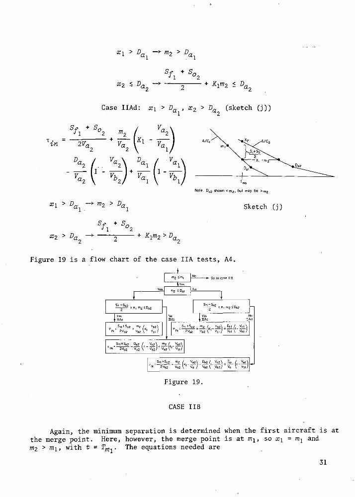
Case IIAd: x\ > Dn , x2 > Dn (sketch (j))ci u
V.a.
Vr.
V,a. Da-. Va.
V,, V, 1 -a. 7&,
A/Cf ^A/C
Note: Do2 shown <m2, but may be
Sketch (j)
Figure 19 is a flow chart of the case IIA tests, A4.
1\2 ^ml
P ' K| m^ - ^O(!
r.
TIN
1
g
YesHAo
S,, + So2 m2 / Vb2\
2Vb2 ' Vb2 V'1 Vb, J
NoEAb
STIN
S(l+So2 Do2 / Vo2\ m2 / Vo2\2V02 V02 (' VbJ' Vo2l,
K' Vblj
NolAd
Vb2\
V02\ 00 2/ V02\
"
Figure 19.
CASE IIB
Again, the minimum separation is determined when the first aircraft is atthe merge point. Here, however, the merge point is at mi, so x\ = m^ andm-i > m\, with t = Tm . The equations needed are
31
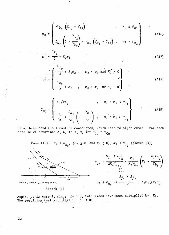
(A16)
(A17)
X2 =
or K < 6
(A18)
V, (A19)
Here three conditions must be considered, which lead to eight cases. For eachcase solve equations A(16) to A(19) for T12 = i. .
Case IIBa: x2 < D. , (x2 < m2 and K2 > 0), x^ '< D (sketch (k))"2 1
T =in 2K2Vb
Sj?
Note: m 2 shown > D02, but may be < D02
Sketch (k)
< D
Again, as in case I, since Ji:2 ^ 0, both sides have been multiplied by K2.The resulting test will fail if X2 <;0:i
32

Case IIBb: x2 > Da ,
Sf + SfJ l J z m \
\n = ~2J^~ + W^2 {Kl
\/ :V«21 -I-;
a. :Ti>,
1 m2 and K2 °)> ^l - Da (sketch
i J2< K2m2
mi <
Case IIBc: . x2 < Da , (x2 > m2 or X2 < °)»
2< Da (sketch (m))
1
1 °2
+ 51 °2
< £L
m2 Sketch (m)
Note that, as in case I, substituting the value ofK2 into the test forx2 < m2 of case-IIBa or IIBb gives the tests determined above.
33

Case IIBd: x2 > Da , (x2 > m2 or K2 < 0), xl < Da (sketch (n))
A/C?
Note: m2 shown >D02, but may be <
2Vn
"Sketch (n)
X
1 2
Case IIBe: X2 -
Da ' 2 - m2 and K2 - °^> xi > Da (sketch
Note m2 shown >Da2, but may be <002
Sketch (o)
ai I ai
*\ ( - \
34

Case IIBf: x2 > Da , (x2 < m2 and K2 > 0), xl > Da (sketch (p))
Sf + S-p /„ V^fl T2 Wl ./Xj a2
v
*~~rnll \ ^l/ U2
1-
-P "" -pJ 1 ^2
< K2m2
Case IIBg: a:2 ^ c > (^2 or X2 < 0), xi > Da (sketch (q))
+
T/in "
a. F.
Sketch (q)
x2 < D
SfJ 1
3:2
35

Case IIBh: ar2 > D
a ' ^X2 > m2 or K2 < °)» ^l > Da (sketch (r))
A/C2
Note: m2 shown > Do2, but moy be < DoZ
Sketch (r)
T . =in 2V'
a. D,
1 -
Figure 20 is a flow chart of case IIB.
CASE III
For this case, the minimum separation is determined when the secondaircraft is at t = Ta . Note, however, that this test applies only ifMax(rma, TOTl) < Ta2 < 0. Since the value of Ta^ depends on the value cal-culated from T\2 = tmed> the procedure is to first calculate tmecf, accordingto the conditions imposed by x\, #2, etc., and then, for these conditions,check that the value of 2#2 is acceptable. The equations used are again (Al)to (A7), with t = Ta :
7.ul1 - —
"I \ Vb- V^ T,
1,
(A20)
(A21)
36

*• Go to cose HA
tn, / K2 Vb2\
" \ '" Vb, yvbl/ Va2 Vb2
m, / K2Va2\ Do 2 / V02
2VQ2^' Vb, ; V0 2V V IN" 2Vb2
Yes
_£
Sfi+Sfg No
m, <K 2 D a 2
YesUBe
Sfi+S f2 mi -/K| Vb2TIN= 2K2Vb2 Vb2\K2 Va,
V0| \ Vb,
_S f |+S f 2 ( m, /K| Vo2
•IN' 2K2Va2 Va2\K2 Va,
+ rrMl~
<DQ2
NonBf
Yes No
2Vb2
Vb2Val
+ rr- I-VaL
2V02 Va2 V0,
Vai Vb| Vo2 Vb2
Figure 20.— Calculation of T. for m2 < m^.
37

(A22)
X2 -
Or
(A23)
GA24)
which leads to four subcases. Further, to test the acceptability of thevalue of Ta , one must also consider the equations for Tm, if m2 > MI> andTa if m-i .mi- These equations are
Tma
m.
m.
1 -
m2
Da
1
1
1.
>
1
1 ,
>
' ^2 — ml
. m2 > mi
(A25)
Note that the form of these equations is identical, the only change being in •the choice of mi or m2- ^n tne sequel, these equations will be combined intoone equation, with m . = min(mj, m2)•
38

Case Ilia: (x2 <-m2 and K2 >. 0) , xl •<. 0fll (sketch (s))
< m2
P/lNote: rri| shown >D0)l but maybe < D0i
Sketch (s)
To check for applicability, use/>72
Note that this will not be satisfied unless K2 > 0, so a separate check forthis is unnecessary:
S,bfl + Sf2
max
. > KiD, , m . <Dnmm ai
27, min
Note that when mmin > Da , the left side of the last part of the equation ispositive by the test for xl <.Dai, and the right side is negative sincemmin > Da • Therefore, the inequality is automatically satisfied if mmin
> Dtand need not be checked.
Case Illb: (x > m or K2 < 0), x^ < Da (sketch (t))
lmed
x2 Note: m | shown < 00|, but maybe > D0i
Sketch (t)
39

S j? +• jS's-.-i'--A ' °2
Note that K2 does not enter these equations so its sign is not important:
S + S
T' < 0a2 •? ~< Da2 «2
(Sf +.S0,J 1 °2
max(T T • V < " T —> •\' "I/: «2 .;
+ K m . > P^ , m . < D„l mm #2 mm a\
, m .• > £>mm
where the second test is automatically satisfied as in case Ilia.
Case IIIc: (x2 < m2 and K2 > 0), xl > D (sketch (u)) .
fJ l
5fJ 9Da.
med i -
D, V.2
a.
Sketch (u)
J
This test will also not be satisfied if K2 < 0:
a.< 0
40

This test is satisfied since the test for xi > Da is satisfied, and thereforeneed not be considered: 1
max T T \ < Tm' ma
, m . < !)„mm Q!
J 2
mm , m . > D^mm «i
Again, as in the previous two cases, the first of these two tests is includedin the previous tests, but now the test can never be satisfied; therefore, itneed not be tested. Also, if the second test is satisfied, then mm^n > Dai;if this test is not satisfied, case III is not needed (so tests for m .are also not needed) . 1
Case Hid: (x2 > m2 or K2 < 0), Xi > Da (sketch (v))
Sf + S DJ\ °2
rmed V^1 -
Da2 1Va-.
A/C
Sketch (v)
Sf + 5^Jl °2
* s 7^
This test will always be satisfied since x± > Da and therefore need not bechecked: 1
max
f (•) m .mm
+ 5
+ K m . > !)„ , m . >l mm a.2 mm
41

As in case IIIc, the first part of this test can never be satisfied and soneed not be tested". Also, the test for mmin > Dai can be omitted. As shownin figure 21, where the tests for Ta < 0 or max(T a> Tm ) < Ta2 are not sat-isfied, the value of T j is set to zero, so that it is ignored in the maximi-zation process for 1, .
_Sf,+Sf2 Dog /K2 Vb,med 2K, vb, Vb, \,K, Vb2
Figure 21.— Calculation of T •,.
If Ti2 = max(T-£n, if{,n> tmed) > adequate separation will be maintainedwhile the aircraft are airborne, but the second aircraft may still land beforethe first aircraft is off the runway. To prevent this, an.additional quantity,io, is computed which controls the spacing between the aircraft so that thefirst aircraft will be off the runway before the second lands despite errorsin the aircraft's maneuvers.
42

RUNWAY SEPARATION
The interarrival time required for runway separation is defined byequations (10) and (11) . The partial derivatives used in equation (10) aredefined as ,
12
80.'
aot _ nom80.
where T is the negative of equation (3) or (A3):
Tnom
m m < Da
With this equation, along with equation (1), the various derivatives can becalculated as follows: ,
92712act3m
^12aot
™a
9T12 aot
^
92J12 +aot821 „
•of
m * Da
1Vb
m
\2
m > Da
1va
V 2-7, 2
•a- vb - .„ „„ ' -i nV i "ITl2a vf b
Va2
Vb~Va m
a ~ vfva
' r "bl ~ v a
All the quantities needed to calculateavailable. nom
equation (12) are now
43

PROBABILITY OF ABORT
In equation (10), a value for AT is determined. This quantity is anallowance to be added to the runway occupancy time to reduce the probabilitythat errors in arrival position and velocity will cause the second aircraftto abort, that is, if the first aircraft is not off the runway when the secondaircraft wants to touch down. Thus, it is desirable to determine analyticallythe probability of abort so that a desirable value for K is obtained.
The probability of abort is a function of four random variables (<S7a,67£>, 6p, and &Tvf) for each aircraft (a total of eight variables), each withan assumed triangular distribution. The resultant distribution of deviationsof interarrival times (sketch (w)) is essentially Gaussian. Also shown is
Probabilitydistribution
AT
Sketch (w)
AT, K times the.root sum square of half the ranges of the n individual tri-angular error sources. The probability of an abort is shown by the shadedarea. To estimate the probability of abort, first assume that all variableshave been normalized and have uniform ranges. Also, note that a triangulardistribution function is the convolution of two identical uniform distributions.Therefore, the probability of abort of the n triangular distributions is thesame as that of 2n uniform distributions. Thus, given the density functionfor 2n uniform identical random variables,
1 1 , o < a < 1
0 , else(A26)
determine the probability that
2nz = x. < x - T
^ s^=l
where Ts = Jn. Thus, Ts corresponds to AT, with K = 1. Using Laplace trans-forms, the moment generating function <f> for a single uniform variable is
i
44

-sarx.. "t X .
^
-so. , 1 - e2 • da = —-s
(A27)
From,this, the overall function <f> is
-ks(A28)
Taking the inverse Laplace transform gives the density function,
2n
Ek=o
(-1)
t < k
(t-KL2n-l (A29)
(2n - 1)! , t > k
which can be integrated to give the probability distribution function:
•t < k
t > k
2n
E /2n\ -kC-1) '
\ k1 \ K- Ik-o x . -
E ( - l } k
kl (2n - A:)!k=0
0
(t - k}2nl .
0
(t - k}2n
t < k
t > k
(A30)
To determine the probability of abort, evaluate equation (A30) at t = x - Tswhere x = n is defined as the mean of 2n identical uniform distributions, thatis, the probability that Z < x - TS is Fz(n - -frC), This evaluation yields
45

F(n-
kmax
(-1)'\(2n - k}\
C-D'- A:)!
(n - v n - k]2n
7 (n - /n - k}2n
k > n -
k < n -
I(A31)
where /cmax is the largest integer k so that k < n - Jn or kmax = -£n£[n - Jn] .
Table 3 gives, for various values of n, the values of k g , Fz(n- Jri),
TABLE 3.- PROBABILITY OF ABORT FOR VARIOUS n
n
1248
kmax
0015
Fg(n - Sn~)
0.00491.00615.00670
Z9
~oo
-2.58-2.50-2.47
and Zg, the normalized Gaussian variable with the same area under the left-hand tail as Fz(n -
Figure 22 is a plot of Zg versusn. The previous calculations assumethat all error sources are identical,that is, each has an identical effecton the landing time whereas, in fact,each has a different effect. Toconsider nonidentical sources, assumethat n - 1 sources had identicaleffects and that the effect of thenth source was to vary from that ofthe others to zero. As it varies,the width of the probability curvedecreases, and, by definition, thevalue of AT also decreases. The neteffect should be that the area to theleft of AT will change monotonicallyfrom the probability of abort due ton sources, to that due to n - 1sources. From figure 22, note thatthis probability is very insensitive
4.0
3.0
2.5
Figure 22.— Effect of number of errorsources in probability of abort.
46

to n and, furthermore, the probability of abort decreases as n decreases.Therefore, the probability that the actual error will exceed the RSS of 1/2the ranges (which implies K - 1) occurs with a probability of less than 0.006,as stated in the text. The Monte Carlo runs showed the probability of abortsfrom 0 to 0.006, which agrees with the above analysis.
47
APPENDIX B
PROGRAM LISTING AND DESCRIPTION
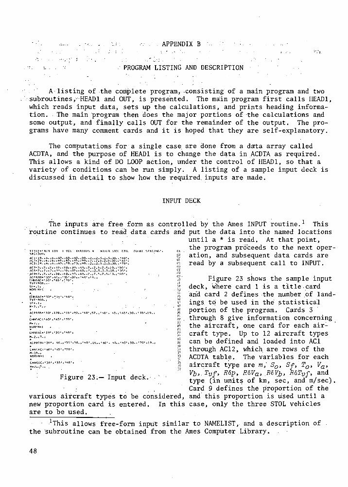
A listing of the complete program, -consisting of a main program and twosubroutines,- HEAD! and OUT, is presented. The main program first calls HEAD1,which reads input data, sets up the calculations, and prints heading informa-tion. The main program then does the major portions of the calculations andsome output, and finally calls OUT for the remainder of the output. The pro-grams have many comment cards and it is hoped that they are self-explanatory.
The computations for a single case are done from a data array calledACDTA, and the purpose of HEAD1 is to change the data in ACDTA as required.This allows a kind of DO LOOP action, under the control of HEAD1, so that avariety of conditions can be run simply. A listing of a sample input deck isdiscussed in detail to show how the required, inputs are made.
INPUT DECK
The inputs are free form as controlroutine continues to read data cards and
VARIOUS M Ml Xtn STOL CTUL 60IJAL SPACING 1
AC9
1 = 19.?=19.3=19.
8 = 7. t
,6. .6t 6. tt,
2.,?..
. ,60
. ,60
,30.
,65,70
35.
,65.,70.
35.,
,90.,90.
60. ,
,7. ,2.5,2,2. ,2. 5, 2
2. ,2. 5, 2.
.5,30
.5,30
5,10.
, ' 65, '70
•3-i'
ACPRflR= '30' ,',n. , '35 ' 30., '40' ,19.,C H N G A C = ' 1 0 ' , ' 6 5 ' , ' 7 0 ' »TVFsPOO. , • " -SF-.l,NORllNsl ' , ' .
CHNGAC='30*TVF=9on.,5F=.l,H=2.,7.,
.35,
ACP
CHNGAC= '60 ' , • 65 ' , ' 70 ' ,
M=7., •<NORUN=1 ,
*
H-2.,7..
ACPRnB='30 ' , 40., '35 ' ,30.,' 40', 19., ' 60', <•!>., ' 65', 30., ' 70'
*CHNr,AC= ' 60' , ' 65 ', '70' ,M=19.,NDRIIN=1 ,
CHNGAO' 30', '35 ' , 'AO 1 ,M=2.,7., .
070309 -
222321252o27
3233
3*
37
Figure 23.— Input deck.
Various aircraft types to be considered,new proportion card is entered. In thisare to be used.
led by the Ames INPUT routine.l Thisput the data into the named locationsuntil a * is read. At that point,the program proceeds to the next oper-ation, and subsequent data cards areread by a subsequent call to INPUT.
Figure 23 shows the sample inputdeck, where card 1 is a title-cardarid card 2 defines the number .of land-ings to be used in the statisticalportion of the program. Cards 3through 8 give information concerningthe aircraft, one card for each air-craft type. Up to 12 aircraft typescan be defined and loaded into AC1through AC12, which are rows of theACDTA table. The variables for eachaircraft type are m," So, Sf, To, Va,Vb>-?vf> R&P> R&Va> .R$Yb> R&Tvf> and
type (in units of km, sec, and m/sec),Card 9 defines the proportion of theand this proportion is used until acase, only the three STOL vehicles
allows free-form input similar to NAMELIST, and a description ofthe subroutine can be obtained from the Ames Computer Library. .
48

To reduce the number of input cards required to run multiple cases, theinput procedure was arranged to set up a series of DO LOOPS. With this pro-cedure, it is necessary to first indicate which of the aircraft types is tohave variables changed by the DO LOOPS and then to indicate what variables areto be changed, and their new values. If more than one value is specified fora variable, the program will compute for all values specified, as in a DO LOOP.If more than one variable is to be changed, nested DO LOOPS are created. TheseDO LOOPS remain in force until a new indication of aircraft types is specified.
The particular set of input data shown in figure 23 computes landingrates for the following cases:
STOL only mSTOL = 2' 7
75 percent STOL m^ = 2, 7 m^ = 19
75 percent STOL *STOL = 2, ?' m^ = 7
50 percent STOL msm = 2, 7 m^QL - 7
50 percent STOL m = 2, 7 m = 19
The remainder of the input cards provides the information to run these cases.
Card 10 indicates that, for the first case, some data for the threeaircraft types indicated (CTOL) are to be changed and cards 11 and 12 indicatethe required changes to Tvf and Sf. Card 13 indicates that no calculationsare to be made at this point (since more changes will come in the next call toINPUT). Cards 15, 16, and 17 make the same changes for the STOL vehicles,while card 18 indicates that computations should be done for STOL = ^ anc*mSTOL = 7 an<l has thus set up a one- level DO LOOP that will be gone throughtwice. Up to four values of m could have been provided, and additional valuesfor Tvf and Sf could also have been provided. If two values had been speci-fied for both Tvf and Sf, then there would have been a three level DO LOOP,with two values for each level, resulting in eight sets of computations.Quantities that can be changed in this fashion and used to control DO LOOPSare m, So, Sf, To, Va, V^, Tvf, P&p , E6Va, R&Vfr, and R$Tvf. If all these vari-ables are used, an eleven-level DO LOOP will exist, with up to four valuesfor each level, resulting in 107 cases. Obviously, care must be exercisedhere.
Card 19 again indicates the end of a data read, and only two cases (STOLonly, WSTOL = 2, 7) will be computed. The output from these two cases isshown in figures 24 (a) and 24 (b). Card 20 presents a new set of proportionsof aircraft types and, since there is no reference to CHNGAC, the previouslyset-up DO LOOP will be used for the next cases (75 percent STOL, mSTOL = 2, 7,mCTOL = 19) . The output from the first of these cases is shown infigure 24 (c) .
Cards 22 and 23 indicate a change to the CTOL aircraft data, to set^CTOL ~ 7» and cancel the initial DO LOOP setup. Card -24 indicates no compu-tations. Cards 26 and 27 change variables for the STOL aircraft, and again
49

set up the one-level, two-value, DO LOOP (75 percent STOL, msTOL = 2, 7,mCTOL = 7)• Card 29 specifies 50 percent STOL, running the same DO LOOP(50 percent STOL, STOL = 2, 7, mcTOL = 7) • On card 37> the last case hasbeen, set up to run (50 percent STOL, msTOL = .2, 7> mCTOL = 19) • The Programwill continue to read data cards until they are gone, and then it will stop.This particular input deck will compute data for 10 cases (as previouslystated). • • . • - • • •
Two additional subroutines are called by the program. The first,RANDU(IX,NX,R), is a random number generator and (as used here) will returna random number, R, with a uniform probability distribution from 0 to 1. Thevariable IX is a starting point and NX is the starting point for the nextrandom number. The second routine, VTITLE, prints a title line and pagenumber at the top of each page of output. The title is read from the firstdata card.
DESCRIPTION OF OUTPUT
The first three pages of output from the sample input deck are shown infigures 24(a) through (c). The output includes not only the information dis-cussed in the text, but also some material which is not discussed. Thisdescription defines all of the data in the output..
In figures 24(a)-(c), the first line is the case title and the second twolines are general heading information. This is followed by the "A/C DATATABLE," which gives all the input quantities for each type of aircraft usedfor this.particular case. In addition, the individual partial derivativesrequired in equation (10), along with the root sum square, are given in thelast five columns.
.The next two lines define the probability that the next aircraft is of aspecified type. This is followed by a table defining the interarrival timesand available takeoff times for all possible sequences of aircraft. The firstline defines the type of the second aircraft, and the first column defines thetype of the first aircraft. For each possible sequence, four entries are madein the table'. The first, PROB, is the probability of that sequence, obtainedby multiplying the probability of the individual types. The second item, .T12,is the required interarrival time, as calculated by equation (12) . Immedi-ately following this is a letter, which defines the T with the largestvalue, using the code indicated. The last item is the time available fortakeoffs, which is the interarrival time minus the runway occupancy time ofthe first aircraft. -
Some histogram information is presented next. The total number ofaircraftin the histogram is specified. The histogram shows the distributionof interarrival time and available takeoff times, as calculated from theinformation immediately above. Also, average, maximum, and minimum times areshown. , . . • .
50

LUCD
i— o
CJ
200
I
LUX
CnCD
III—oi oo
ooLU0.
I U_ O O CD O O OI > O O O CD O O
I Q O O O CD O OOI—
Oi C Q O C M L O C O ^ t OOLU>tOtOCOr^OLOoi r? QOiO to LO *d- CM CM i—LU
ooLU_I<:OOOOOOs:<>oooooo1-H I-H Q
I— I— CD CD CD CD CD CD
• I O-Q I Q I
OO
^-
CM •
co en co r^ ovo co CM ro LO o
LO <3* CO CO LOi— i— ro CM CM tx.
oILUCMCOOILO^J-LO
-o _ i iH- Q i
LO oo co LOi — rO CM OJ
^ O L O O O L O O«=C «£ to to r*. co co ^
co> U _ O O O O O O
UJ1— O O O O O O
LU i—i Oi i—r—i—
oo :
O CMQ *Z 00
CM ID _lo LU<:OOOOOOLU LU^^LOLOLOLOLOLO00 O Q^ Z O i C M C M C M C M C M C Ms; oo LU I-Ho LU es
OS: Oil— ^ O O O C D O OII II I-H O O O O O O
Z CM OO CLO-^ OQCMCMCMCMCMCMi—I g O- Of
LU O L U O O O O O O O C 3
LU —I1-HLUOOOOOOO LUI— > O O O O O OLU > I— cncncncncnCTio
• —I 00
o I>I-H OLno«otoo
I— (_)cC 00
ct O • --v.oz: i — o i l — S o o o o o o
>-< QO_^<a ;oLoocDLoo oo~\Oi O CM
>. o: >- o o oOZ^ cCLULUCDOOOOCD <H-o o s 2: ooOOO ZI-H O O O O O O I
X Oi I— COO CO
o- oo2oooooo oo<C 1-1 I—
Q I— U_tOlOtOlOtOtOLU eC OO00 Oi OI
o[I
><
o
IICMx
OOO. — •COLO LO.i — i — • — CM
O O O S
_LU
. ^ O O O O O O
l—i OVQIOIOIDIOIO2 I O O
oooooo......
CnCTlCTtCNJCMCM
OOCO
>-I—i— i
LU _ I0- I-H>-co1— «t
CQOO-^.D£< Q-
g
CO CD OCOCM
CD O
O CD
0 O
oooCM
CD O
01 CDCM
LO O
i— OUD
O O OICO CM
r— 1O- o o
o eni
O O LO
"~ CD O
CD O
O O
O CD O
O O
O O
O O
O O
O CD O
IILU
P
<: to exra: • a:
O1 OCTlOCTlCQCJlCTlCTlC3 i— 2:c^ a:Q UJ2:: O._i o
Q-o
I— CM I— i— '— oo o CO co co coo o ocncorOLoroooo«=C co <=tcoocyir^i^
o
CD
o
o
a:or
^Dc c .^CTtdi—
ooO
O
_
o
o
I ^CMCOLOi — COCOCO
o(U
1— ICL,
exo
00z:oi
r— i— C O O C O C O P O C O
o
o
ooLUU-o
i 2*1 en cji i— co to i— i— i—• O e t C O U O C O L O O O O O O
Qi O 'u_i— o oOca
oI—
Oi
CDi-li
C30•HtL,
oco o a<C C'
-o
O
51

CM
O
CM
LOCM
0
•z.1—4
CL.
Io-UJ
CDt—O
— 1O
CO
UJX
E:COZDO
<:
=>
cno
§
o
ut—o; co
OO 'Z.
E: nO CM
0 *•z. oorv y
CM
LU
5? co0 UJ
CD £II II
1—4 El1-
UJ
UJ
UJQ
00
og
_l U_
o-z.1 — I
c_> ooor
•a: UJ
0 Z
oo oXooro_0_
UJ00
00
Q_
\—
CJ
•=£
1 U- O O O O O O1 > O O O O O O
1 CD O O O O O CD
P.or o csj LO CM «3- r--OUJCOLOUDOOI- - I — "3-or ZD =>UJ
ooL U _ l e £ O O O O O OE:<:=»OOOOOO\— \— O O O O O O
o;U- =Coo- r--cocnror^o
1 1JO OO CM CO LO O
O 1 Q IO LO -=3- CO CO LO• 1 i — • — i — CO CM CM
CO
«* o• lUJCMCOcncMLocn
h- Or— i— i— COCMCM
•^•^ O L O O O L O O
CQ> L u O O O O O O
UJI— O O O O O O
LU i— i o; '~1-H I—1—i— i > C O O O O O O O
QTi— 4 or CM CM CM CM CM CMuu u_CJ
ZD — 1
UJ i—iCJ3•z.ori— Soooooo
1— i O O O O CD CD
O O C M C M C M C M O O C Mo- o;
CJ UJ 00 O O O O CD O
_Ji— I U - O O O O O OLUI— > O O O O O O^* 1 — CT> cn cn cn cn cn
• 1 OO_j<: — oooooo
-J y >-i O L O O O L O O
<C 3= >I— CJ
•a: oo<co • -^1— ori— E :CDOOOOO
•^ 0e C U J U J O O O O O O
z: i—i ooooooor I—
2: • E:O O i ^ O O O O O C D
<C oooreC0-LU
• S CD O O O O O
£ 0 VO 10 l*> 10 VO 10
Ol-^&OOOOOO
El i — i cn cn cn r-- r--. r--o a E: •— •— i—
orUJ
o
3
o;oro
II— 1
oIIX
tx.0
•z.U-1—II
CM
oCMX
orOQ
o o o s:CM CM CM F-1— r— r- IIu_ LU i-H E:o o o
0 r- r- 1— .—
LO CSJ VO CMcn r- i- E:000 -
E:
i — i
•3- ^3- ID r—1— 1— 1— XU- U_ 1— l
i — i — i — LD OCM (--. r— cn
LO r— 1— r— 'Z.o o ro i-i«a- i— - csj 1—
LO i — r^ it
COoo
UJLO o o;oo o • • <=C
H- o oo ooi — CM C\J UJ
cn u_ i— 1 1— i E:«d- CM • • • i— i•3- i— O OO OO h-
t— O OO LOO O O CM CM CM 1
CO CM r— IO O
\— or CM i— o I—1-1 CM 0. ... H-
uj _i LU orO- l— l O- O>- CD >- 1i— <: i— •— iC_>O CJ-^OLOOI —- or ^ - ^ co oo *d~ ^2
co o ocoCM
0 O
0 O
cn oCM
0 0 O•3-CM
LO cn
0 O
0 O
OO LOco **
O CD Oco
- — • r-- UD
1-1 0 CM1— CMCO1— I LO O
E: o cnUJ1— O O LO
O r—~-^ o o
or o ooh- 0 O
1 — 1^ o o
o o o
0 O
0 O
0 0
000
IIE:r—
Z CD O1—1 LO CME: 1— r-
x co oof LO CM
C\J CM
C3 CM CM> cn «3
CO •00 "OCJ3 CO •'Z. _l h-
CZ1 >• LU
«C LU CO
OO 1— l ct
CfZLi-t
i— z E:
zc
UJ1—
C3 CO
o "~
— 1
*
LNDN
GS
1— CMc_) O«=C oo
u_o
o
zc
UJ(—
^ 00
z:
E:o
00CJ3•z.CD.
E: CM0 0^ ooU-
0•z.
oI— 0
oro
1—oro•a:
1—oCO O
u_0
o
CC.3:
LUI—
-OT r— ^O CO r~* CTl r— OO LO
S!i — OOCnLOCMCTih-
LU0.o
o•a:
CO
LUO-0
u_o
o
3:
UJ ""1—
i — LOOOi — CTli — OOLO
oil — oOCTiLocMcnr-~o_o
E:o2:
oo•z.UJ0.
SILOLOOOCTlCOr^CMOO
U- '~ '~
0
00l_i_u_oUJ
1 — i — ooyD«=J-«3-cocooou.o
O V O C O O C M - 3 - L O C O O
oo-LUor
E:
o
0oo
LO
0
<n
LO
o
0
LOoo
CM
0ooII
oo_o
•d
ontinue
o1
3Cli
CD
1
f — vJD\ — /
CM
CD
•HIX,
52

CO
CD
Q_
CM
LO
O
C£>'
i — i
O-
o-LU
_J
_1o1—oo
LUX
2:oo0
o;
•—
01o
z
0
III—C£ OO<=C h-
OO Z
E: nO CM
0 *Z OO
CM
LU
E: oo
• 1 — 1
o s:M no --*.i — i ^~
LU
LUQ
00
OQ h-
1 U_
o RO
i — i(J> OO
0
X0oro_
oLU
ooo_(—
£
i LL. O O CD O CD O1 > CD O CD O O O
1 Q O O CD CD O Oo
or ca o CNJ LO ao <tf- to
Q' .— . ,— i*. _. — . ...
LUOO
t— H- O O O O O OOr
LL. cCCD O- r*"«. co cr> co p*-* CD
1 LO CO CM CO LO O
Q 1 Q LO LO «=J- CO CO LO
• _J LU CM CO-Cn LO f LO
O C_3
CO> L L _ O O O O O O
LUI— O O O O O O
LU I— < Or•— • f—I—
C£ >— i Or CM CM CM CM CM CMLU LL.CJ>
LU i— i
i— . O O O O O O
OClCMCMCMCMCMCMO_ Q;
O L U C O O O O O O O
LU(— >• O O O O O O^> 1 — en cji cr> en en en
CQ > i— t O L O O O L O O
o
fecli-'^ooo oQ 0_ K-I
>- o<LULUOOOOOCD
Q; ^101010000000
oa^oooooo1— U_lDlOU3lOlOtD«t oo
Q.LU •
El i— I CT^CT^CT^CMCMCM
to• o
0 0
COo
LO CDUD
CM
0 CDIO
OUD
O CD
LOCM
LO O
!•-
O O
LU _JD- i— i>- ca
c 5 CD
LO«3
o
Q
"*
OO
r
PoCO
CO
C£
LU'o_>-h- .—
10 W5 1C
1O ^Q 1C
co co co
co oo a>^- i—Oo o o
CM CM CM1C IX) VO
C\J CM CMCP> CT> CTi
CO i— 00
O O O
000
Ll- U. LU
O O OO O O
00 CM i—000
O O OCM CM CM
LL. LJ- i— i
O O OLO LO LO
^- O *£>in *f ojo o o
555
r— ,— en
LO ^- o
0 0 f^
O i— •—CNJ CM CM
^J- LO « -
«— O O
O LO 0
or
LO t-O *-O ^CCO CO CO 3
LO «3- co a:o o oo o o or
i
CM CM CO IICO CO LO 1
CM CM CO +— -en en *— CD
i — iten r*- - xo o o or
o ^»- LO n
o <d- LO-—CD CM ^ CM
Q
•— 0 0 CMO O O X
ceoCD.
O O h-
i— 1 1— 1 1— i E:^^ CJ^ r—^^ ^ *
CO oo en CMr— r- 0 El000 -
s
1 — 1
LO CO CD IIOO 00 ^1- i—
LO CO CD O<D Ch CD
CO i— OO 1—CM CM r— II
LU
OO UD OO
OO CO COCM CM CM I
0001—
1
0 LO 0 H-
co o o00CM
O O
o o
0 0
000
LO O
U3 O
UD O
OO OLO
CO i—
S ^°
•— « CO CM-^i CO i —
E: CD -3-LUI — o co LDQ •—
C£3 CM
1— O CM
1C O O
o o r--.
CD en
o o
o o on
. .1-1 CO CME:
X CO t~-
f oo coCM rr-
' *
> IO CM
CJ
oo •oo -o
1 3 1-1O > LU
3 LU CQ
OO l-i «f
0 Z <
i— z s:
3:
. LUt—
or
Q r—Z CM
C-J
OO
Q
_J
(_J ,
ea: ooU.o.
o
ILU
Sr-*
^
c^
CI3
Q
O 0Z. 00
u_
o
o
=« 0
o
1—o
u.o
1.LUh-
. ^ i ^^ IJ-' L*> CM {*}
00
ceLUQ.o
^COUD^-^Cn
^ i — en co LO 'sO
LL.o
o
a?
LU
CM CO O^ CM CO2:cc " * r"-« LO LO
Q_
o
LUQ_
• LL.
O
ooLL.OLU
1 — CO ^£> LO CO CO
U.O
O ^O 00 CD CM f
o-LUcr:
s:
LJ1 U) t__)
1 CO CO CO
UD^^t-
LO LO LO
cn LO o
CM CM CM
LO CO O
•a
ocoof
4J
a3
i— (
Ii
/ N
O
J.
CM
. <D$-13M
•H
O Q IE i— i— i—
53

Next, data on the landing rate are presented. The Monte Carlo processwas used to determine how many of the landings were required to abort becausean aircraft was attempting to touch down before the runway was clear. Theabort ratio (number of aborts/total number of landings) is printed, along withthe nominal (or planned) number of landings and landing rate. The actual land-ings referred to in the last two columns are the nominal landings minus theaborts.
Finally, takeoff information is presented. The first line, of this table(fig. 24(a)) is read as follows: if all aircraft use 36 sec for takeoff, thenthere will be sufficient time for 1089 aircraft to take off without interfer-ing with the landing vehicles. Since there are 302 landings being considered(given on the previous line), there will be a total of 1391 operations, at arate of 90.7 operations/hr. The last two columns consider the effect ofaborts on the number of operations and the operation rate. Since there areno aborts (see previous line), the actual and nominal operations are the same.
54

X"?
•on• ^
~3M
C*-J^H0-'5.<
^2H-.
LL£
OCGQ£CL
•- "~~~ •*ex ~
•- [s^
CX ^_< -1— ""•s: vj-c —
*— *^— •.
<!-^~1—I—
_jLLCt—— v^•- -
—Q-c1—00
2ccccaQ.
o<
CX - -s: — —I— CM CM
_ „! r-l I-' OO X
2— x^ — LL •- C-O £ t- H- u- 2 aC^O CM •— ~ .- <• CL
C f-i OC »• •• OCLL t_ O — - 2 C
— — CNJ OZLL K. !~- — <.—<t— »_ •• I— y 2"00
O _ >- I-I-H C LLJ I—
c£|_ LL'^ a: Si x »v_-i_i Q. (\; Q. I— ^ CM 00L L 2 f > " v - O — _ • • r t L L
•• - LLJ • I- _J~ ^ Q- ^H 2 CC— _J > •—i LU <
_ - , ' - | l - v ; " ^ t - C LL >—C M i - . c c — r < C - - H C — C cc^ ^ C M I — « - • - • • I — C d J <
Of— — I— ^ C CL 2 *• oo >< C C L n l — •- • v. o ir>, C CL L U C L C kCLOO C M C M — 2 C G - « - » - C S I > O > >< C > - < # > - < • £ C2I- i - t - h -O < _, CL I— O I- I- •- C,<2 CL X X — — cj
CMl— 1— OC ^ — - J - X C l T . — 2 OC •• K- 2 S 3 —1 C •-"Cr^ —i— < c CM' 2: o • c < 2 x < « - * c c _ j —^ > v O l / ; » - . ^ « - < >t- » c£ *• >—i 2 ; - - < ' ~ J C t O <•—IT. < >-, —- ,-i LU < K — — IT, • . >t II ^ C ^— M i l l — • - "Ct -CCM C\ i - ^LJ |— 2<J" ' -<CL LU CM C C '"' — UJ LU°^LU ^ ^-^ — — "t— ^
" 2 ' ~ ' C ; 2 C Q i r O C : C M •• II ' H •• I-H • • , - C . m i v j H C C L LU C — i_U LL O; 3; •• _ LU o O- IT, <h- •- ^ - » — • - < • • «.C r-icLL'2.^M 2 > ~ L U K OC O Q. °- OC <' HH CV ^ _J ,-j 2 Lp, LU 00 _J II « 1-, " HH CO C* • < LA _l •-• < I— — <; H _ - ' > > U J | |
CiOOoo^ i < > O X 2 < >-<~ _« _ H | | O ll|| '- |Ci:%c< Q- 'Z2 _J t— H- LLLULL 22~ -^ — i— —' c s " ii i— ii^-i ii z « c > - < r ; c c •— ^ w1—00 LULU <>-<<:< || _l I— o I— I— CC CC Q i X Q i l — | | 2 x 2 — 111— ' ~ ( _ l l l |— O C C C C | | I I 2<i- Sj; >- — I—'I- —I H- *~ h- C. OCcC S c C ^ O 1 — < ^ " « -1 2 -J ^ , C M < j C M_J> «-„ < O < < X < L L 2 C ^ o o Q c t cCc C < — < £ 5;. O LL X 2 C < X c < c C ^ O c r l SZ;LL,CC. c. u-' c c: >-, o .-, •— c, •-• •— Co. i— i- K ^ - O O _ ; I — h - ^ 1 — | - H I — Co'- 'o o c c — — i— rvOcc —'-J IT. -C C CC . C '- -I - -<I p-H i—t
o
oo ooo o ooo o
55

c\j ^CM C
Z —
° S1
.2T CM IV
C - 2 - O ^ *c: i-- c K- <- cvCM H- C *.
— t- a: C— — ~~— -~ • -- . — — -~ -- _ . -- — _ j_ ^ C CM < C i—cMcMcMCMCMCMCMCM'- i . -<r- i , - i , - i ,-(.-<,-( ,-H a: ^ t— < f- a.1 - J o O £ i : a : a : a i a : a £ a : a : c £ < tvi c r; c
: -5 — : — > — . — -3-3— -5-2-3 ~ 5 I - -u- C 2 : 0 . ^ 0• . • • » • . » » » • . » • . » » » ( / ; (Vex C LL S: ", t^- c m u- , vc or c c--^_ i_ c —•
L L . C CM (\J >5I C - i f r v ;t^|_CV < f\j Q. 2: ^a * ^ • - ' O
< \ J + _ J C tVC, <: _I H, fV . C I- < S£ t/1; ^ - , r v . o o ^:. > < LL 2: I— a. _J > ^4-
I— O(NJ+ rvj |_f\ i< (\j •> K _l «r-i< > - < » 4 <\J<; < ; ! < ; . . . •-',-<™ in^-_ l<C°CC O-v Z .i-itNl^-ClC!^ CCO f \J CI, 11 i, II || II || tl ,| (I H II ,1 II || II 11 ' UJ U_ u_ C CM <M . > li fl > II oo C oj — 5: ^ > " m > II "-1 -H
1 — UOuO1"1 »— * O O l l C \ J f l C N J u O L L 51 •— ' rvj (^ M •^ I I ^MLLLL<^ t\i t\i ex • - ' " . '— li »_ LL Q LL. i/> rv; <; C c\j < n C ^ N J ii~r-i<C; ^< ^ t/lC < C t \ j C < f-t d - ( \ i o o t — ^— Q - O t - o . C Z i_) — ai s: I— C l— h-C — n
C V j ( M > C M c x j _ i ^ i ^ ' ^ H ^ ^ , > _ H _ J r t 51 ^ II » -1 2 -_J Z HH C1^ ^c LU2
<t«5<CCo D S: : i i U.<< <CCC; C O U-LJ.171 C^LL < U _ O < LL|j_ Z^LL* 1 S'-'-CC'-'C:c.> c. > v. h- t< t^ <s, c> c>i- i- <_; i/^_</: c ^ — > i- cr > HI- u-t-:^,(_; K-<>I-C
• ______ " cvir. . f- cC\J f\J CvJ fCi
OO O O (-J O
56

C\J
C
1 — *s:ivjjt.
•-1 cM
II C
s*"X c.rv'c
CM
^ yIVJ fs^l
\ -JJ-CM_, C--H inU-rv)00 „ C
"-• -002; C!J/:|v- C
(v.m
2 CX*~~t xt"1—
Co: i—cLL C
c;CM
UU ,-H00 <. _<<I C <O • >
I— , 1 LL __l .-CC 5: . > ||
r-si f\l ii •— i*- H s rt<< C~ LU§I— 5;LL ££, i— io^ txl"-. >(_
C
t-H
in rr'
iiC-1
LU
<£>
CX>i-
c<xOCV
+' M.CM -it
C C , l
II '-' ^rtLL M
G II •— <^ i— i ^i— 100 jrK 00 N,
LT,•J-
CMin
rr. C1—
C2: c<. c;rx —
LU <
X •1- '-'c CCS
MLU +
wcr-
2
o1-cin
<;>
C\J< tM« C IT, CC
> 'i in >II <M II
CX O ^"^ O H- H*LU^ "J-1
cc1"1 G • *>i- c >
f^;in
M
f— 11—LU
CC
s.IV.'
1CX1-LUCC
yrvi
• +c *~^II ^
CM 00< ~CZ II
H-. "— '
t- 1-If.in
*— t ^(— L
< :K 1-
£s: :C -o
L
2 0K-l <
K L
LLc *•
C
2 HLU 0
m
C
U C rvi^ 'C; v
> CX CM-, < cL' . +0 i— <M1 C5 C_) v r-4
CMU-21 00
i ~ s:- LL 00^ •— 07
i— t « — i
V ^IVJ IVI\ -\
-CM C C\j
Q LL)l Coo
A 1 1 1,IV * II
C c oorvi C i/-.
r*-m
C
cc;
CX
c,IV,
i— 4 •
V <;
IVI f~~.
'•'': +
C ooII _
^ LLC ,— .^ .
cvC
cr-c cr
•c
i- a cc-e c c c
1— H- LT
cx C C CXii C C V
f*^ f"S^
1- OJ rt K-1 V < -I*=-* C C •
C rt • 1- Cs: < t- <^^.M > — < O « M+ < ^ CC * S. "^"
00 11 II OO 5; OO00 _.-H C 00 (V4 00
^s ^LL 5; e: c u- LL "-— K > C •- >— •-'
CX"C
ZM
l )
GO
T
O
66
+ Z
.M2
/\'A
l.L
T.Z
r>
K2
/VH
l+n
A'
• H
I- CO-1 >
•C • -v, «
QLL LL ^
C1- — 1-
<• ^NC -C
O O OO O O
57

GA
Ml+
r>A
2/V
B2
-Zn
K2
/VG
AM
l+T
Mr>
Al
>r-l .
CC^>00
II 1/5.-< II
SIC<gLUO'5I>t—
CCNC
cc- •- o
£cLU
C^oi-
cr>c
cLLK-LU_!CLsico(Xi— 4K
c£cLL
OO1-00LUt-
_J_l<
AC
IN
G
FO
P,
RU
NW
AY
CL
EA
RA
NC
EO
RT
ITD
Ll+
TD
LZ
)
CL 0000 +
»-H
UjC
— IICL — J5;ujccOK
Ct^
00
t—
00
C
CL<
LUXI—
LLC
x<iSI
LU|—
CL5TCo
-4-
(\JII
-3
C\J^r-M*c~?c
_lLU-)C-,•- II••*
z —LL1
•> -.C^LU~
51 —t-f-••K
<i_ ••-IHI-C
•00 —
z->*~~ ' — 3<„ UJ
I-K C21- ZC_ —CJ 1—
zI-U_ Cl-i- O
(N
1—
(NJf— 1K-
oo nLU *~o •-<>-, CLo: 3H-^ ^<. ~> c\j5:~ o
H- -3i— —
C M S<™ OMO-* -i-Jl- 1-
1—
X<s:
UJX1—
oo — r-t- ^ C
— KX — 1O _J fV
"— ' IXI •— IX rvj 1-~S II II
00 ,_| ^H
LU (X Cfz -, ->LL r CXLU o 0C -? -3
1- |- £•-1 .-. Ca: Q: i—0 0 H-
JR
1 )
= A
CP
RO
B(
2,
ICO
L )
*AC
PR
OB
( 2
, IR
C)
•exo~3
51CCCct:a.
Ccc
TR
IX
CA
LC
UL
AT
ION
S
<.SI
LLC
CzLL
00
<CLOCKoo»-*X
LU1—
£tSICo
c1—1—£^-
z<
rvcv 'Cc ^i— i ^-i t— i— •— 'h- l_ 1— 1_ I—
I U-CL a c>- > X2I X2I(_ H_ _ „ _ <^, 2:21 00xx ,-1 -< ^H si s: cc LU2:21 — — ar t ra r t - i— H-I— ~•• - 2 -J -3 -3 -3 -J
^ - i ^ - i C C ^ ' - ^ - ~ — — ~ <- - ct:ot\ i(Nj(\ ixz xz > a:l l l l i - ' - 'OOO<'-SISI CL
— 3 -> -> s: s cc z it3 — J L U L U - — 1— H- (—1— < (XC C a . 0 . s ; 2 l 2 - » . •. LUrt
C ^ O > > - t \ i C c C l — h- 1— h- Sit—«-<'-'t— 1— •- < *— C*-1— 1 O_|O +
•_,•->(_ -h- Q; •» •.< LUQ-;OO CL<NJ<X CC Z 1— COO c II I' II H •"•' <-t 1— 1— H — 1—t-H I-H || I— h- t— 1— O CL ||
•r-i <v tx1 C —_ — _ < s: a:QOc^O^- . l -a rL ' -LL LLu_^ CccC.C--II-I-CL'- '>- —— x <~- 1-
"
ctQ--X-c1-1—+CLCCCH-II
CLCCc1—
1 L
AN
DIN
G H
IST
OG
RA
M
. +
1.
0 tvt— -jz \i— (X!
t-H
1- t-zB "0 Z
uo o o o o o o o
58

m.CM 'ii inz •
.1.
*%f\!7r-^" f .•rvi
>-*OK
•CLZl,— ULL<i•-*:
i_;<^+2
1t—t—00
II
—Z
_Jh-(—OO•— <
21<occcKoo
u_ inLL (Mo •LU ,_i II
* +<cz1- .
fM "~*C ^int— \ CMz •~CH"
1- Ol-l- 'z z« II ~G LL<_-z<-
<•x.'+
z
1—1—00i— i
II
^v
Z
C1—1—oo^^
51<CLC
t-00
X
Z
LJ\<
LLC
cZ^->
<_l^<.+ 0h-U <C< _l
II II 0o^-> <<< _i_J— ' rv,'
cC
Z<—I
t-
o<
_J_J<t
CL
LL —
•LU .— <2_ 1•— OK <
_l_l ^<I —l_ -;;-0 (_ CC
(—II U1- HZ J
oo5
£
ctQ-
CZ<3
Cf-t-
t\Ji—4
I—
LL
OOLLJ_JCC<t—
1—Z
CLQ.
CL>-1—X51•.
r— 4
II
Of— tr-H
;C
Q.>h—X
^-tII
/— * ^^
a; i—^ =s
CM r—1 Q.'•+-* ^1
< _1— —C C
— O^-iH-. < -1— II ,-<LU • — • ••
a *-• <.> -~ —H-. ~ LUII C (-^-i cx: _oc a Q:- <3
Ci— t
XCM
IX'r- (
— t-
^< X•• (M
X •-CT^ CC
xC' ct:•- a.
*?- ~< ••» xx f.ff, -
- 1— 1CM ULL' -xa. <>-Ki x0 CM^ -~<
o Z!X -4 >f
—1 -1 ii-— ». CL
-c >-— h-
t- >-x< LU <s:•s:*- z \\or _ CL^-O ct OxLL S LL2I
C •-!»-H -(
a>-i—x^i — t •_*n —
>—LUa.
0(^(T-. ,_
^ 11i — 1
OtfC-,
O->1-Xs:^HM-j
0-3CM v.
•-< -J-
c^c. -.
„— 3—LUCL>"1—
IICM0
~
00LL<_)
a:i—<s:
LUI1—
21Ocr:LL
ooLU
_J<r_ —>— i--i
c^^o: .. ^LL'r\i<X'MLJCJ
zj~CC£
XCfMt— Qj i-H
2 II II
t— rO (M
S ' 'CrorOCC -3 — 5Q^ ^ • — •
ego<tx Q£OQ:Q:-«
— ii•4 -^X X2;» o:
— i CM-7 Z
— >——3 — II
— • •S <fa: u_ u-'CL - a:<j 1-1 <_ <.. •- 00
— 0 LU^ • s
— Q; in •—_.-( -3 LL I—r-iOi •• ••
a;-7cM r<l -i— «.p-l • <
»CM — -t Ur\jLj < u. «-i
^"- 1 " "~~ G r°i ac!-•£< — C:«C h- 1Q.-I- - 1o- „ 4-~ LU
II II C <C 1—— rci -<r c^H ,_| X^, Z
| — <M _<com, ^ — »--2 ~5 vC -C- ~
Kt-~ I-""H-— ;r LU <LU <Cci- s^sC^OC i-t D^H« QCct a: a: C- a C«S LL3. U-
c c c cCM ro co -J- .
a:<iLL_JLJ
><2:Z
o:a;
_iLLci—u_i
CII
•~i— 4
- x(X'xa:
io;c^C;LLLU>~•5~ M
I-U-II —s.
(X<cII
X1"1
a
_j
00LJ»— H
h-00
1—<(—00
LL(— ->
1—a:<i—00
O O o o oo o o
59

LL
C
IIQ_
X(X
-cLL
cLL
CC<
ct1
<sLJ
•aa.
-H LU *•a. x
n > —•
0.0.
(X-c ••rHX |-
•~ -£~ X
1—1 CtfX JJ _l ||
C C.LJ .
a. —< ^•—i CLQ: •-< O
C. LU X—' Q H-^S >• -ce i— —
- C o.
CL-: <•jj a. _,Z > -ILU I— <C ~ (^
tvCL : CL
Q-
(XCL
C. — —< CL CL
•» o. a.
X • • X X ^- I X X
I— —I fXC CL • CL
• X XI
cLJ o. c. c. a. o. a.
I— t- K I— I— ' t—
r- -j-
- ~. or- - aC. Q- t\J — C C + c. c.
o. < a.-.
cto.
LT.
Z. > ct
CL Z —i a: >- a: > ~ ^ a: >- cr >-or rx i— i— < i- (— ct cc
_ii i — a. _j z _j z n > _i z _j z — >—I II —1 _j II _i II • —I _j II _j II n —1 _| II<^X_, LU <j X < X rt LLJ .^X.aX^-.UJ <X
rs jo rc . - c. t vc i :<ccCc .c ;en — z z or — Q. LJ o LJ (_: o
l-ct > -^n n ii n li itZ —t- n exn n —i c\j c\j ^ ex LL f\_XrtLU o^-Ct < S. > C
O O
60
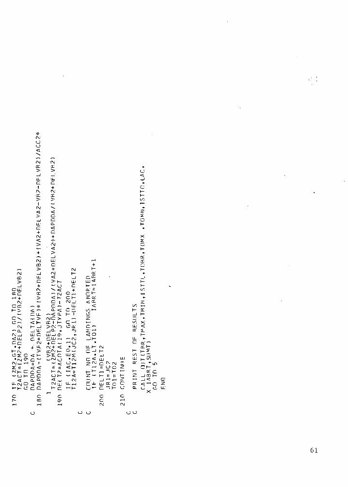
*_,
CMCO>-J
CLL'
ccc<-< +
CMCcC1— >
V
Cv,
CM-CM _j<LU£*. f~\
• i
^"~ (\JOS C
•IM CTCM — •— IX IIrvj f '— O h-
^U-CM O*- ' j— (^
Cp--t— t
CM0o•a
CMCC>_JLU
^1
CMCC
*l
rv<^;>
iLL1
c.f.
fM
>
—„
fMCO>
i
UJC.{.fMCC
^-— •
-*• -< -~*C LL^- ^< I—1- -J_J LliLLJ CO *^
fM
+ LL.
< h-c —II IIc co ca Q-rzc
cCOT-H
CMCC>_JUJC+CMCC
w
^<coCL<C-+
fM<,
_JLUG+ fMCMI t—< -J> h- LLJ-o c"^ < -f— CM C^< 1- Cl-C | CM_I
C. — LUd. < Cc.
— < Q. 1— 1CMC > —CC 1 1- C^-l
>CM —> c a:jQ. ». ~^
LLJ_I a- ••C.LU rH — CM-f c — • — ' oCM + *C • ~?CCfM h- O_^>^ C LJJ y_rvj o "tx
"" <^ O ,— jII II < K-I- r\j *- n01- — << _i rv
l~ c ^ 1 —(
Co*^
«.
c;•a_j»
C^_>-_
•-^yC;1—
«.
X^*i.
I—
a:• — ' -r+ C1- 1-o: *
C.CC • _,LU I—t-1-1 t~o; i.1 <^C^ -ceo:<CC Z
<i t/: t—^^•- I- XC — i 1—^_ — ••>-< V. XC— LU <-Z-r* °r s.< O 1—_it- LL •-
c or-LL 1— fM CC 1—Q 1 | — J— | — X
• i t/; ^- Q < LU LU LLJ |_ 1/1^ C M c - r M r M " C C - ^ - L f s
•-i II O C Z Of-H* ^ " « — i '1 — *~* ^~ CC C~2— h- II II *— 2 _JCC|—— . I*""1* — 1 ^ ' — ' 1*3C V U - U j C C c C C C < « QO •- C. ~ K <-' C L C J e,
X
c cc •-•rv c\J
C2LU
O
61

a:CLLJ < C
I U"
j. •t\i •
•J — ir ,
cs.
c
. c
<
C2
c<
i/-, x<ELJ "
U_I/O 2-
< C Cat u -
C >cc Xa ex
_<: IO IT.
. — *—r~ rv• — • • — iU-' —CL S> oI— en
1—p:
c2•a
LLc
UJ
CC
- < — X •J C
<o: < cz: x LJx
—i X - -'
a < c —
X i—
? J. C X ~-
- - <L C
o < ^ < ^ -< I- — K _ —2 C LT. C: _ rr
CL "Q.C-
d -2<
c c-^LJ ^-'!
:< ~;' , . <^ •
c —<UJ Q.
LU 2 eg;x " i— '~ i
*— 00 '-'•LUX 2 °°
ccc LU <
X I-I- <
^ Oo. c
— _s- X —a: LL
I/-,
CC<
X C. o: ••i/' rx
CC.CCLJ LJ- LJ LJ<- C .
h- <C LL2 QT
< CC •
or ^_,< LLJ
<<£ cCC c
LJ
Cc C c
< <
1-1 2?C
2 C33oi
^u.
C H-(VLJ I
i— < C <X LJ X.
. rf. < rf.
c/5 «< h-
ir,I LJ• <
»•—- D-a. — cQ: i- "i"^ C ~f. *• ~,
< .-x
< ^ < — -
fNj "-I I—I •—I
>*• ,-!•->-
I II II•-1 II >- —!! — >-,
^-> _ _ c c|| ^LO LJ I' C U
— -fr -5—' <. 2 n Q-
Q.2 h-
CLJ
Q_< 2
<-'
X i
-H— < - LJ
K CC ^O X
C -^ < LJ#. •• •. LJ
:-L LJ <
X I- X <NIr<-, C f, n
~r-.°- -—-
^c£ Z~l
rf. (v
UJ <io: LJ
LJ) LJ O LJ
62

I/)LL'CL>-1—
O<
r-
CLCLL
t—~
CLz»— i
sca:LL
><o:o;< r-
».cc --<C IICL H-.ao o< r-
r—t
1—
LU Cor C
OX.— t
1—
cc
. —^~* •
LU C00 •
Z: i—*
LL' •Q. —> —.1— ••
r\jO —\ r—
< Q:a
on LJ•— t <~
i _t—o-, a.•— ' >—
ccC•a:CL
O<
»~4
_) LULU Q.cc >-< 1-_J
— — ooCZ •"-* *—• ' — 'z •• •- x< (X ~< t-
— — •<s. c c o:Z at a: c •C Q- C. LL ^•- 0 LJ |H- < < <CL II II t- uC3 ^~ ~~ <C ~~~Q^ >— ' »— . d t i,"~ »• «. .
CL ^ -, U-1 (X
a ~" — & —CC OL UJ
LU cr c x co: a: a; t— CLC Q- CL CL1- <-= U 0", (_jo-, < < >- <
vC, — ,
Ct-
cc;
^^^^->
fX'i— i—<i-cO<
•
CLU
•. — .
>_INJ »i — i i — i•• -
— < ccII C~> Ct
Q. ^O —
c < zIT. _ —<-< 1—
ZCa CC H-, 0
cLT.
<r~
r^2
•yi<i.
•£.. ',CLCLLj
_ <t_
•- Zf— < ^"^— .
cc -C -CL «i"CL <;o "< -
o\
— <c -IT- -
1 — ' '~4 ~5C u
4. r~ ~. u-i— ^-f-1 —, ~
K- .11 ~ ZLU *~ C- ^— t II *~J
I- S C (- 0. t-P-H or |_ _ >. za: ^ oo — H- ^3. LL Z ^ "— O
C C CLO vc r-
LL'_]a:<_ii — ><;>-<
0^<
LLC .-<
1or ,LL IiQ- 0.> >H- I—
XLL Z
C ~^ f-H
LP ..O' CC j_
— ' r- -1 cu •
Q. a c „>- > ii- t_X x C LL2 Jl C P—
Ccc
•cr.C~ '.-V
CL
•
s.~^J
1'-2_<
i — iII 0",a-u..
P i-LA. . — ,^- ;
, ,1C<cc,•""
— CLC CL•
CoLL.\•<c
a •>-:X'C
*-zX ^- IIs: s:-a CC
LL; OI- a'
LL ,j_ CL
i— ^_ 0".
irK
x.•CL •
CL•~ iy.
^^»- ^^
'(V —• — ' •-cc ex-
^ —CL- CCCL
CL o CL Q: —> < > CL •-<1— I— O ••x + x. < o, Z?" ilL — •-* *L••cc "ii cc -
^C ^H ^ CX
- CL — ct:|| CL II — , CL CL II
00 ^ >- 0^~> 'X' ~5 (X H- <; "
II - _ X |,c Z —• ' cc £ tv;o- cc ,— cr r- „ cr— i C i- ^ a: ii — i ^
a .7 CL -C Q- C C L_: 2 CL -C^O C<^ 0— .
C t-iC C
— -»— H
•*(X• —ccczCLCLCJ
<
+— *,—1
1t— <— •ao
n
• — ..Ci.o
r^C
C^c^
^»— <
'~~LLCz<XL_>
wCa LL.- •£.c_! C. 1—cC 0^-
LL'
CL —~r~
LL <1— *
>- or< <O_' >a:<. o^
Z<. *~h- <
ctzCL C— O
K- <•LL-1"o-. C
1. C1 rv
\Ht—
;C
. —•
ct
H-;•
• ' . —" — ' 1
•- ,.I—1 ^H
II ,
1—1 <
1—
-c c cII (V1 -V ^ LL»— , d t—
CCr-<"
C
11
Cli-'
— •c•
oLU
•CT
id'•— H
.—
LL
*-'
oo o o o o o o
63

cLLC
ILJ
UJa:
t-c
— OC
— _J
1— LJC.II 00
— LU
•* f-H l~~l
•-< + LD— C< ^ H- || , —< C LJ
c
c
i-. C\j -5II II —~ ~~> <.C- 1—^x \C f~._ f— < -
_l
LJ *— • LL•— c •—
LL
cc.
ct
X
LL
o:
LL
LL
LL.
IX
—1 *•
~ 1 —-. C<. H1— —2: "" UJ
LJ -J £~- »— i
< < H-• / — -^
< <• CC. C i_
r-l
a.
c
LL
ri—c
'LL
I/; — <U_ 12: -f i-H II II
— ~ C. — LL)
•*~ *v' ^-' ^~
^^ c. *^* ~^1- t- 1- hj 1-
LJ <-• C LJ C.-- -• c — • (-,
t-- C•— ' f\.
cI
zor, •-,
l/j
1 —
t- C.
< 'X'
LU z: ir,
z • i z
LL' C•• > C
C.C X
IjC \ Ct- < __•
^"LT Ct; • iia K-. — cc
LU 2 n e •c • -- 2 G
II C 2; X LUZ2- •*- Cil **- LJ *y — • tJJ *4" — • *~~*
|— —LL LL ij_- C ix LL
-,— ' O.C. H- -'
tx
II—5
cro
^ •C-
ir
i—
^ <LJI—
LU —a1-"
\ — —<. X 21
L_' ^~IV— h-Z Z
LL"— l_
Cf
1 —
C
c
X
2:
LJ
i— Z
c •-X <^
— . LJ
f. <•c -^ X
1 ff -,n I—
Cu LL <r \Cl— S h-1— _ Q".
^ a — ""Z i LL c
(*"
LL.C
ILJ
LUX
h—
LLCL
\—
a'
•X II
•— ' "^ o:c ^ v
oc • —~> ^ ~'- II Z~£ (¥ ~'
•-• ±i ~-
> -
r"
n
i— ij^i -^• — • — . ~- '*— ' 22< i— * CTC t- 1-^ —
I CL,' (_ LT
C Cf~ <
LJ
X
1—
LL"
C LL— i Q-
K ^
"~ c"""— . c <C •-'(-
LL ••
• — —0.' 1—v - LL' <j
— 1— £•— a:
LL ^-' C•— X LL
C CLT C.
1M ,-.
Q II^ '..-ii/~. c:^ i_
CC
LJ LJ LJLJ LJ
64

L/VaC
, <; «- r- >— . v ~, C < _ J -C H- — h- h- - I—Z *— •-• IT :i - »• a' LJ CL *-
_> M •• •-.' -i _,' CL u". a: <_'SI t\. - ^ IT LL I - LL
C' C v. -^ >• — t- S I C - V.i- c- 5t - <; - i 1—3-
21 iT U- 2 LL ^ - £• - - X- _!
<i - x <; ct: LU C2 •—• •--C > L: a >- r-
. x —i •• z: ct - <c^ LT » < r~ < 'j. - i-
(V LT •- - h- tX 0.' CC -
t*- t-
LA,QLL1 —US.
1
'J-.
LLQ-
Uz
LLa_
a:LL
Cu C-.
c. I
.C
c - -iXj _ r^-i- ^ or
CL " C _ •-, i— C. _^
LT
C
«a - ixj < < >— •• LL C- CL -o: c L_- LL - h- - .- i- - -z: ir LL _ - <; i - ^ 3--
LJ —' ^ — C < r_ rx: xC i—
<. 'J-. - U~. - LL LI LA, I" » -•• LU •• CL' C <y, > - - LJ
U Q. <^ IX! I ~ - - --L ~^
•• LL C "^ £ '-T- • _• I— •- C - C. C.
I— < ii x I— —i - «. •• rf, i— •• j- •• ,—ix ZT .C C i-i • (X r<". LT. »• ow (— <c ex£ - ~ " a : ^ - H - — c ^ ^ i — - ^-i ^ r^ r—i
^ •— CL V - J-' -i I— •• CT I- - I- H-— >JI— Q . I I - ^1— * - - ^ - ' • ' t y ^ * - »-
-c
u
c
c
o:LL'>
oo
^
>- c<; LU
LL
:-L
LLH-
CLU •—
i— -;:•
;• fx~•"" n
_l II (X
cc
v^
01
cc
•>
cX, — 1
en
LL
Cc
cc - -;: ~LU ». cr 3— x ^ SLU C 2: CCJ (X - ~ uLLI ..
C
1—
•"* <X ^.x}
_.- — • <r
< \ iy, i_— < —i LLCC - C -a >. - »Q- r< - >J< o- •* <f- i- i- H-
LU ~•£. -
1—
(XI
1— -
o- >
< c c —i- Cf - II
- vC CC ^0<- rr.^C ,_C1- t- 1- l-<f
<. < CC LJ LU
"vC
<1—
<_;<
a:<1
LLI -r-LH-l-
ILL1
(X
CX 1-
, <
1 O O
65

— *-rx
CC1
LL•
(X-v.
,_;
••
rx
<i—
LJ<H
r^-
<vil—;c ,' LJ --,< r
CLJ<-;;••
rx^^
—^^
—(— «*.
C<":, .
<t—C.{._*
<1
^- * —»-H >— 1
«. »
rx re1—4
< —\- <
Cl 1—
LJ C< LJ— <-t 1
• •t-* (XII II
CC: Xt
< <
t— 1—
_C rxC£ LJ ^ LJ«» < ^< 1
—• — *».
xC
—<1—cLJ<
1
—t— i•.
IT• —<I —CLJ<,+
— H~ 4••
r^
<KCLJ<
II
vC
<:i—c
<LJC<
vC re.• —< Cf- h-CLJ C<£ .•N^
,.-1
•- -~IT-. —^-- ^ (
< -1- •£C' ,—H
LJ ~< <1 K
• ^^LJ"!'• •— h-•_< ^r-
»• •
-CCT.r-< LU
"-- •
< -M
1— *
LJ i-i< •-II ,-H
ccc
< < h"^ *""'<<-JLLC.<«-
rx.!;-
-:;•*^, — i«.:
•— <•- f, H-
C LL, C— • LJ< .— 1 <i — -;:- -it
LJ — rx.<i « — . ~~\ »• ^*.r<-. •£ —LL — >— i
» < ••r-i H- C
% c ^ .-~- t_, •-'(—1 ^ <i
" ' t• — ; • • —<— < rx LJC<5 C ~ <
K ~v -;;i— C i— — —
« ** *•S u 21 cc <-H
^ ^- ^™-Q^ T^ i-v* f"" ^ if-^CT.— ( CT' LJ LJ rxLL. LL «z^ • <| * (•<",
O O< II C
;£>_ rt rx cO xt h-Cc _J _, _J _j _i20 C c C C.C cK< K (- 1- (- 1- C.
<:KOLJ<I
1
. — .
— .•>IT,
— .
h—.*~LJ<^-v
rr.LL:
•r-J.-;j. — .i-
•«, — i
< —C. <
\-u: c.IS LJ
<.21 ll
( •-
£2•-I- t-H
<;s: i-C ' — •z 5i- <
crx
•3.LL1—IT.
— •<r ~
»^^ ».•— ' --T-
—— <iLL h-
1— C— LJQ. <^ -•';'• — •<»; ix— .\r<".L-*J
<: •C2. • — i
a: JLC •— •
*•2 a-
^^^ |—
LL i~>i_i~ (_>
It, — i
-> _l^cK h-
-*i-
—r<".i_t;
^: .LJ -i
^ -;:-< —
>-*•*N^ •.
' r— 1
cx ^<-;;- <i•"• i—*~~ d' — ' v_i
•v -
^ |— ^-,<r ,i- ^c -rLJ —«C <
1 1—rxc-;; LJ-;:- <^ •,'-i— i ^•- ,
LT. ^— r-< —L ^-
C f—LJ '.<LJ*— * <,;^-- j
T"
IIrx_iC1-
_
• —(X-;;V-— •1 — '
»-iT.
—<1-cLJ<-;;•
ex-~
—>~~>— i
•-c-—<.I —
LJ<
(X
—• — •*—•
•-
f —
—<h-r^LJ<
1
LJLJ<*^
.,
i — ,•-
LT.
—«tI—r_LJ —
1 ^— »•- -s:*, — •
vC <— 1—< c1 — LJC. <LJ -»'< •.^ (\j
IICO_Jc.h-
r— 1
< -::•-)!- —• ex
ex -"— -::•v. vi-— - i! 1 r~•- i—
— +^1 ;AJ
. — • -;;-<. "I- reIt — JLJ C.
< 1-•;;• +— ex. — -::-- -:;^rx
-c -i— CL< H-t- + —C. ex —LJ -;i •-.<: -;:- -
1 -i C— _ : .rx, t cr •"t— <
IT. — (-— M C<C - LJj ^^ ^^~- •- ~-LJC h-^-' rX rv'<» ^ rx^^ ^- Ou < <J~.
•J- 1- II_)C cC vj (_'
t- < <
tr.(X;
£•
\—••
r— 1
_Jc.i—
>.Ll
Z LJd ^^— < •-
1— —i — i exC --<~ ••^ . — i'_• u
—\s, •-i — —X *~-H- ••
~a. —d ^LL t-
^< LJ1- <
< —. — .
Ci- C•v, <
LU ^C1— ~nr
3. UJI—.
3 "-iC. a*J -i-
(XI•
r^'j_•-^-c
••xc• —
C"LL ^
•-j— .
<"<:
** -JX.fT"
••r— ' . — .
•
CC *-,
LL r-
•-sC
fV^.• <
CC h-LL CLr<~.LJ^<'"^ •• LL;
cc L;u_ •-r —•• > — i
i — i ,.• i/-.
r~ —LL <
~K
1— LJ<<^~ «—
rr^LLLL i
Cc
<XI—
vf.U-! —<LL
a.'1;
LL'Y"_
h—',
~
^
<
^
*•o:17d-'oiLU
<:i—
— <.—i ^c -vt ^
*^ i—4
•C ~. —i— I
\— l!
u-1 < a. -i- Z. C- a i-ac— f.3 LL S
^iC
— -i>»—•Xs;••
— i1!
— ;.-
~».
•—^ LL.' 01l—) dH 0.-1 O-— ' LJ•— <CC. • —< d cCT F— ict ^Q. „
»-
LJ sC
LL^~
^.LL'u.,1— 1- h-" H"H t— »C^ rxU 2 3.
CC
^i.>
— h-~ X>4" - '< ^. ~ .-i^ 1:--* ;— ..CC ,» -*—
X »•-' rx
*- —• o;.'-L' ~- o_> i.t- LJ
<LJ —^v< —• C^
•• rvC sj
I „
~ -1
I- < LL^5T h-a: ,_,^ or:LL 3.
C< — 1
LJ O LJ O O LJ LJ
66

c;LU
crLLi/;Of 3-"LU
- I—> LL
i/5
X
ccc
C-LU •-'U
-cX_t
CCC LJCC C <;
•-< t-i •—i c;* -s; * o z;• *~ i—i j." i— >-< \f. (_;*.*.•. *>fV rr, cc c 2
< < < IT!!^t-i- -~ ac -. c c c c>-i LJ LJ c c a:
" n a!-• LU
o:Q.
iic_
cx^X
— LL
C -
-in - —_ — cc
o —
ZlU
OO
Z I
c,l_>.
U-C
c(NJ
c<c
^.3 LLC 3.
IT, Xt—i
vC
UJ <K- s:, , Q:o; C
LL ^ •— —
i „ —— LLJ
CIT.
C CC Cin IT.
o ci—i •—iIT. IT,
C(NJin
o.C CC (X
c c
cc
II £ O
— H- II
H ij- "-1 c; a c •
c(NJ
67

1—
oo1—LL *
'JL '-a i~Q 1—
H-Z
.~ 1—
X
i en«a.x
I—
00—'j^ i —
CL oo
oo •—
OO X
^1—
a °fr-f
1—
.p.
~~ *~
1 I LL-'
^~Z•-i1—1 — 1 —^;~
< — ' —CtCC
CC' ^
oo oo
X-c
~- ooLP (j;
(X< -
del1— ^H- <
— LT.
(X .-
— a.l-LLH- h-OO LL
^2 -'<—; —t~-<
— 00 |-j— -^ <*£ LL' !>"-S a;oo *~ C
C LL
CCrv
a-
s c
3: (VCC ••H- X —
JL. *• *— • Lp
X X- r-X J~l
C r-! XC Z
" •• ,— i » a:x »C C
— - ,— i "~ir- i_£ _1 •- ,v-LL 00
X ~ CM ..Xvt 5; — - ( - rv a
S x ^^ 00 * LL
••X, - ^ » „X — O I> LL" 1—
< — (V < "~
a: C C.LL: LL'
I— <•—LL, » _jl-C LU x— >- _ - <— *—1 — — ' ^
I- h-H-* <i "C f—•• S." 51 2"
cr f^ac •—
i— LLLL a
i- 1^^c.cP^JtX'
LT, LT.
II "
~' C1— H-i— 1—v/-, 00
». ^
Z ^
1— ••^ X
< C•n t—h- -
•• Q-'0-' £
O f C7< 1- H-*-*
C ^ rvC c CC\J Osj ^* - » - * •
~C ,£ vC• — • — — •LL' uj LL| — ^— | —•~~ -t t~t
CC a; £T2T 3. IS
h—
•X.a
•c
i —a'.
UT
00LUK
a:C
"-1 a;2 K< v^
! «
t ch- -C— C^.
£^ "
O r^^
1—
00
i — i1:c
l
< 0rv; <"-" IX
• ££
1- C <a:. C ivi
o a; ^c M
.< < <•<"> t-— - II <;n n < o;o t o: |_<; < -J CC
i— o:
i— a:
i—CLLL
^ ' < rvXt — i f~ i — 1
1 - ^C ' — 'O —<t l 1
II LL'<< 1-2
H-. SLL
LT.
Crv
orIx,
LL1—
e —
^1 • —LL
• (-
oc
i — i
_ h-000 —
2*C LL
i — i v£• 1 — •— i
JT •- r— 1
c- i-t_r >j-
cc
C «- t—
- 1— • H
»-O IT, •c < LL <r<vj •• LL
C CX vC
• KC7 LP *•2 —i <T
*~ X *"C ir> >Ca x, vTi— t-
x-1 > K
AK
FO
FF
T
AB
LE
i-
01\ —LL
C
»— 1c<ILU±
^
LL.C
•C
cvt1—
ooLLLLCLL:
<h-
LL
Ct^_
0
t—
*z~
CL
LL
C.
QL
LL'5.
1—
C\1 — ' Crv T'•-,_,
^C ,
— h—U_'<1— 211—1 CC
2LL
C*— rv
<cae
Za:LLJQ.C•
1-o<
cF-H
1 — 11—
oo
LL'a.
- i—— oa < .
' — OLU
F~~ •
< C
ct ^
c^ C
a h-C
•T
C
cvC
*7.K
002 —c£ •LU —a &c x
s: LU
EO
FF
S
AN
D
TO
TA
L O
PE
RA
TIO
NS
R
AT
E>
•
ii "-i rv LO
K ^r" °^•J- — «
LLJ II ^H n1 — *-* | —5
-J O — O O
O r^i [ — ; y f\j—i f— C<. C (_ OO Q
O d rxi |-J C-
O O O O o O O O
68

Q_ IT.C LL
ctr -**Q. i-
LLU_
CLL.
<
•~ X
— C• u_irLL LL,
1
_1s£ CC.— <
» <-? >
o; •-0. ^C ;/)CCT t-< H- C
•~r. _ H- 2 — i- ct
-::• H-• — iTi x •*•~ _ ^ ^ ^• "-1 Q;'
Tc — ^ « - r ~ ' ~— ,-i i < •• ••M I— -— I < t— C7 I- H- •-
"~ C C C £c *" ".•-1C «-K — I^J • — xfI . — c: ~ LL -~ -3" CLL
— G- <->-;; CC -;;. LL C "- C- -— LL' <•< • C C- -f X- ( - « • — C "- C UJ f^lx •-* CE s: + c i c ^' -< c - -i— — 21 O CL ^c < "•~> "* —
,-_! tO || H- n ^- Hn — "-"a it a I— LLJ "s: I I Q . < a. 2 i— 2: ^.i— si—~ CLCO. c „ „ or )_ —' ot t- c-^-LL C 2: C < a; a: C LLI a c ^ 2^ - ^ - ' — ^ • - i ^ a. ; s .u -c :3LLa:u-
c c c c ctr c c c c(v f . re -d" <~
f—4 i—I
o o u
69

REFERENCES
1. Blumstein, Alfred: The Landing Capacity of a Runway. Operations Res.,vol. 70, no. 6, Dec. 1959, pp. 752-763.
2. Simpson, Robert W.: Analytical Methods of Research into Terminal AreaAir Traffic Operations. J. Aircraft, vol. 2, no. 3, May-June 1965,pp. 185-193.
3. Odoni, Amedeo R.: An Analytical Investigation of Air-Traffic in theVicinity of Terminal Areas. Ph.D. Thesis, Massachusetts Instituteof Technology, Sept. 1969.
4. Anon: Analysis of a Capacity Concept for Runway and Final-Approach PathAerospace. NBS Rep. 10111, SRDS-RD-69-47, Nov. 1969.
5. Rinker, Robert E.: Determination of STOL Air Terminal Traffic CapacityThrough Use of Computer Simulation. M.S. Thesis, Naval PostgraduateSchool, Monterey, Calif.
6. Anon: The National Aviation System Plan — 1972—1981 FAA. March 1971,AD-756580.
7. Erzberger, Heinz; and Pecsvaradi, Thomas: 4-D Guidance System Designwith Application to STOL Air Traffic Control.
70 NASA-Langley, 1974 A-5044

NATIONAL AERONAUTICS AND SPACE ADMINISTRATION
WASHINGTON. D.C. 2O546
OFFICIAL BUSINESS
PENALTY FOR PRIVATE USE $3OO SPECIAL FOURTH-CLASS RATEBOOK
POSTAGE AND FEES PAIDNATIONAL AERONAUTICS AND
SPACE ADMINISTRATION451
POSTMASTER : If Undeliverable (Section 158Postal Manual) Do Not Return
"The aeronautical and space activities of the United States shall beconducted so as to contribute . . . to the expansion of human knowl-edge of phenomena in the atmosphere and space. The Administrationshall provide for the widest practicable and appropriate disseminationof information concerning its activities and the results thereof."
—NATIONAL AERONAUTICS AND SPACE ACT OF 1958
NASA SCIENTIFIC AND TECHNICAL PUBLICATIONSTECHNICAL REPORTS: Scientific andtechnical information considered important,complete, and a lasting contribution to existingknowledge.
TECHNICAL NOTES: Information less broadin scope but nevertheless of importance as acontribution to existing knowledge.
TECHNICAL MEMORANDUMS:Information receiving limited distributionbecause of preliminary data, security classifica-tion, or other reasons. Also includes conferenceproceedings with either limited or unlimiteddistribution.
CONTRACTOR REPORTS: Scientific andtechnical information generated under a NASAcontract or grant and considered an importantcontribution to existing knowledge.
TECHNICAL TRANSLATIONS: Informationpublished in a foreign language consideredto merit NASA distribution in English.
SPECIAL PUBLICATIONS: Informationderived from or of value to NASA activities.Publications include final reports of majorprojects, monographs, data compilations,handbooks, sourcebooks, and specialbibliographies.
TECHNOLOGY UTILIZATIONPUBLICATIONS: Information on technologyused by NASA that may be of particularinterest in commercial and other non-aerospaceapplications. Publications include Tech Briefs,Technology Utilization Reports andTechnology Surveys.
Details on the availability of these publications may be obtained from:
SCIENTIFIC AND TECHNICAL INFORMATION OFFICE
N A T I O N A L A E R O N A U T I C S A N D S P A C E A D M I N I S T R A T I O NWashington, D.C. 20546


![Untitled Page [jkspcb.nic.in]jkspcb.nic.in/WriteReadData/userfiles/file/public hearing...Nearest water bodies: Niki T awi river (0.2 km, N), Wadi T awi river (0.9 km, NNW) and Ravi](https://img.pdfslide.us/doc/110x75/60ca70e2cf9461409b07f448/untitled-page-hearing-nearest-water-bodies-niki-t-awi-river-02-km-n.jpg)


![Novel mixed anion [trans-Pt(C CTol) (CN) ] as building1 "Supporting Information" Novel mixed anion [trans-Pt(C≡CTol)2(CN) 2] as building block of new luminescent PtII-TlI and PtII-PbII](https://img.pdfslide.us/doc/110x75/60ea8c4070950c2ef949055d/novel-mixed-anion-trans-ptc-ctol-cn-as-1-supporting-information.jpg)