Embed Size (px)
Citation preview
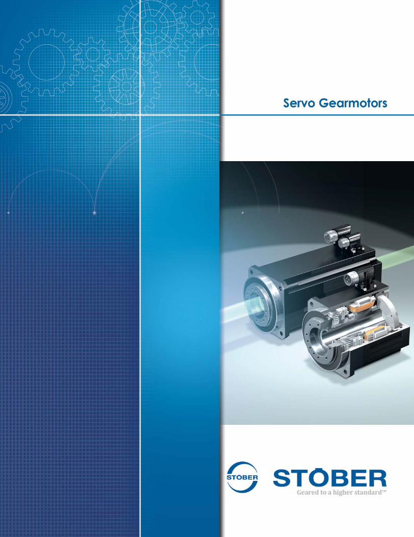
STOBER Drives Inc., Maysville KY
Manufacturing Center1781 Downing Drive
Assembly Center1780 Downing Drive
Geared to a higher standard™1
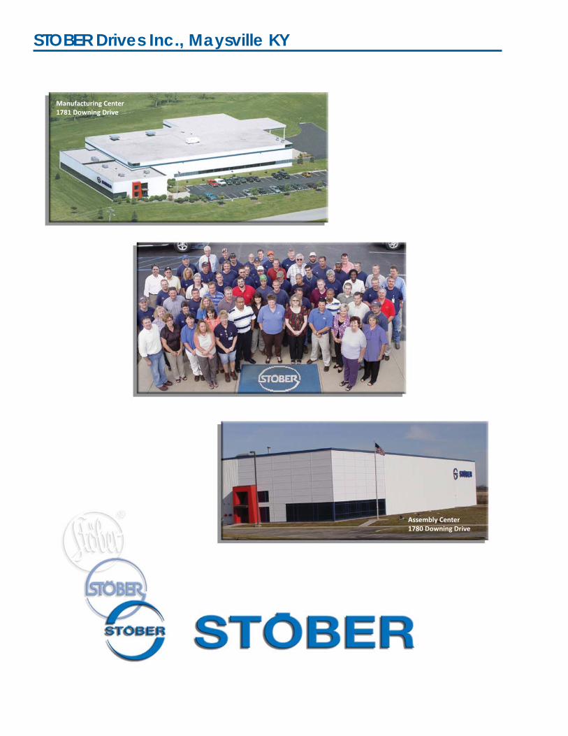
New, super compact hollow bore servo motor
Image of a sec on of an orthocyclically
wound motor coil – the complex, precision
winding technology used by STÖBER for
produc on of the EZ/EZF series motors
A crucial element of the extremely short length of this new motor is the highly modern motor design.
A basic prerequisite for the supershort design of the new EZ Series is the industrial implementation of the tooth winding using orthocyclic linear winding technology. This feature makes it possible to manufacture the stator windings with the highest possible copper fi ll factor. The winding technology increases the motor power output by approximately 80%. For this reason it is possible to shorten the length of the motor by almost half without reducing the power output.
STOBER Servo Motor HistoryEFL: 1st Servo Motor (released 1988)
ES: Electronic Servo (released 1998)
ED: Electronic Dynamic (released 2005)
EK: Electric Kompact (released 2005)
EZ: Electric Zahn (tooth) Wound (released 2010) EZ: Stand alone motor or with gearing EZF: Hollow Bore version PY_EZH: Hollow Bore Geared Motor
EZS: Ball Screw Driving version (released 2011)
EZM: Ball Screw Nut Driving version (released 2011)Enlarged image of orthocyclically linear-wound motor coil.
Geared to a higher standard™ 2
• Geared Motor Advantages – smoother running for optimal performance, dynamic, minimal torque/speed ripple, UL/CE/CSA approved. – All motors are pressure tested during assembly to ensure performance against outside contaminants– Every winding is tested with extremely high voltage to ensure windings are to specifi cation.
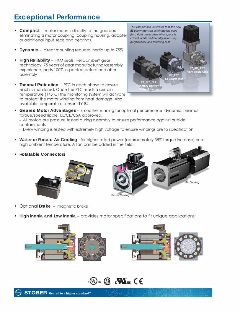
• Water or Forced Air Cooling: for higher rated power (approximately 35% torque increase) or at high ambient temperature. A fan can be added in the fi eld.
• Rotatable Connectors
• Optional Brake – magnetic brake
• High inertia and Low inertia – provides motor specifi cations to fi t unique applications
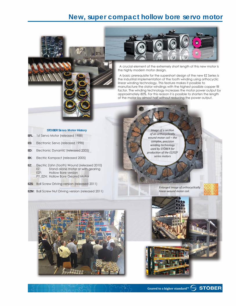
• Compact – motor mounts directly to the gearbox eliminating a motor coupling, coupling housing, adapter or additional input seals and bearings.
• Dynamic – direct mounting reduces inertia up to 75%
• High Reliability – FKM seals; HeliCamber® gear technology; 75 years of gear manufacturing/assembly experience; parts 100% inspected before and after assembly
• Thermal Protection – PTC in each phase to ensure each is monitored. Once the PTC reads a certain temperature (145°C) the monitoring system will activate to protect the motor winding from heat damage. Also available temperature sensor KTY-84.
Exceptional Performance
P7_KX_ EZ7 Right Angle Unit P7_EZ7 EZ Gearmotor P7_MT_EZ7 Planetary Unit with Motor Adapter
This comparison illustrates that the new EZ gearmotor can eliminate the need for a right angle drive when space is cri cal, while addi onally increasing performance and lowering cost.
Air Cooling
Water Cooling
Geared to a higher standard™3
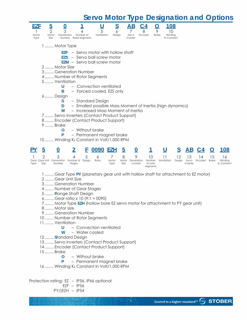
Servo Motor Type Designation and Options EZF 5 0 1 U S AB C4 O 108 1 2 3 4 5 6 7 8 9 10 Motor Motor Generation Number of Ventilation Design Servo Encoder Brake Winding Type Size Number Rotor Segments Inverter KE Constant
1 ........ Motor Type EZF – Servo motor with hollow shaft EZS – Servo ball screw motor EZM – Servo ball screw motor 2 ........ Motor Size 3 ........ Generation Number 4 ........ Number of Rotor Segments 5 ........ Ventilation U – Convection ventilated B – Forced cooled, EZS only 6 ........ Design S – Standard Design D – Smallest possible Mass Moment of Inertia (hign dynamics) M – Increased Mass Moment of Inertia 7 ........ Servo Inverters (Contact Product Support) 8 ........ Encoder (Contact Product Support) 9 ........ Brake O – Without brake P – Permanent magnet brake 10 ........ Winding KE Constant in Volt/1,000 RPM
PY 5 0 2 F 0090 EZH 5 0 1 U S AB C4 O 108 1 2 3 4 5 6 7 8 9 10 11 12 13 14 15 16 Gear Gear Unit Generation Number of Design Ratio Motor Motor Generation Number Ventilation Design Servo Encoder Brake Winding Type Size Number Stages Type Size number of rotor Inverter KE Constant segments
1 ........ Gear Type PY (planetary gear unit with hollow shaft for attachment to EZ motor) 2 ........ Gear Unit Size 3 ........ Generation Number 4 ........ Number of Gear Stages 5 ........ Flange Shaft Design 6 ........ Gear ratio x 10 (9:1 = 0090) 7 ........ Motor Type EZH (hollow bore EZ servo motor for attachment to PY gear unit) 8 ........ Motor size 9 ........ Generation Number 10 ........ Number of Rotor Segments 11 ........ Ventilation U – Convection ventilated W – Water cooled 12 ........ Standard Design 13 ........ Servo Inverters (Contact Product Support) 14 ........ Encoder (Contact Product Support) 15 ........ Brake O – Without brake P – Permanent magnet brake 16 ........ Winding KE Constant in Volt/1,000 RPM
Protection rating: EZ – IP56, IP66 optional EZF – IP56 PY/)EZH – IP54
Geared to a higher standard™ 4
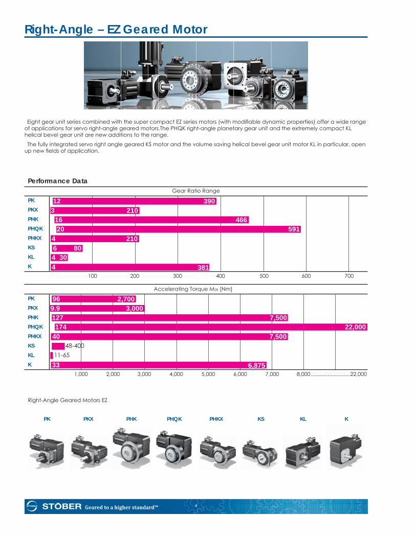
PK PKX PHK PHQK PHKX KS KL K
Eight gear unit series combined with the super compact EZ series motors (with modifi able dynamic properties) offer a wide range of applications for servo right-angle geared motors.The PHQK right-angle planetary gear unit and the extremely compact KL helical bevel gear unit are new additions to the range.
The fully integrated servo right angle geared KS motor and the volume saving helical bevel gear unit motor KL in particular, open up new fi elds of application.
Right-Angle – EZ Geared Motor
Performance Data Gear Ratio Range
PKPKXPHK
PHQK
PHKXKSKL
K 100 200 300 400 500 600 700
Accelerating Torque M2B [Nm]
PKPKXPHK
PHQK
PHKXKSKL
K 1,000 2,000 3,000 4,000 5,000 6,000 7,000 8,000 ..........................22,000
Right-Angle Geared Motors EZ
96 2,7009.9 3,000127 7,500174 22,000
40 7,50048-400
11-6533 6,875
12 3903 210
16 46620 591
4 2106 804 304 381
Geared to a higher standard™5
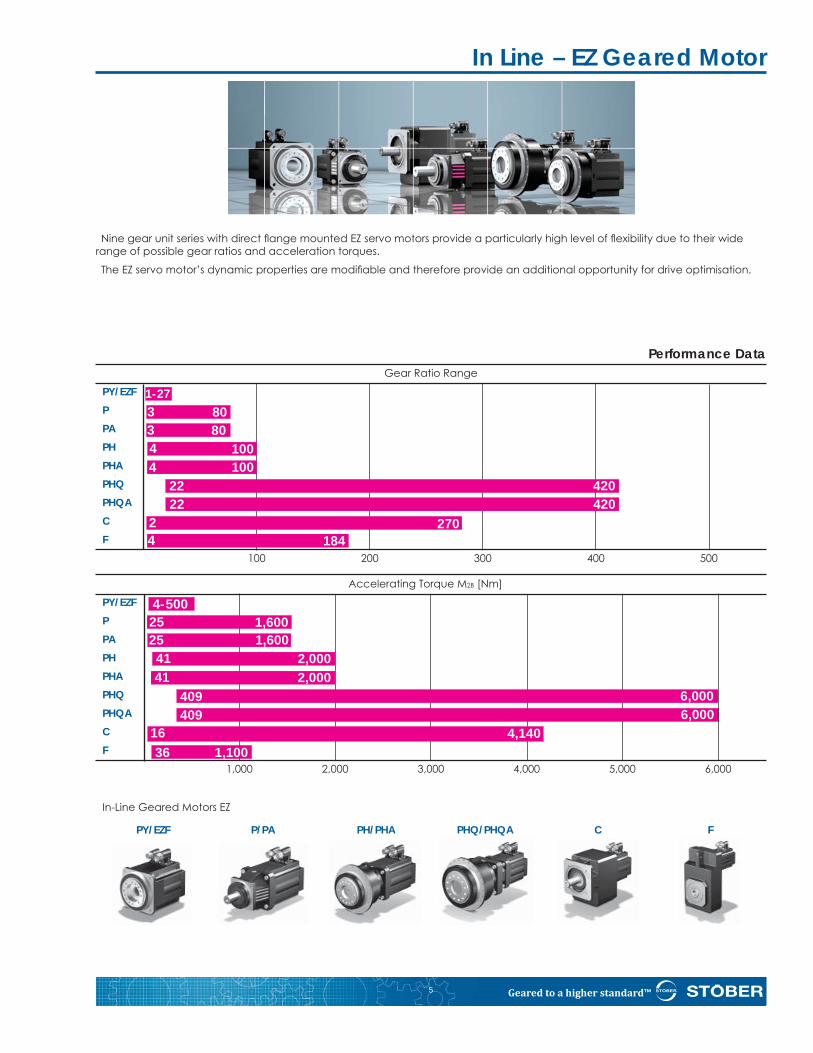
Performance Data Gear Ratio Range
PY/EZFPPA
PHPHAPHQPHQAC
F 100 200 300 400 500
Accelerating Torque M2B [Nm]
PY/EZFPPA
PH
PHAPHQPHQAC
F 1,000 2,000 3,000 4,000 5,000 6,000
In-Line Geared Motors EZ
Nine gear unit series with direct fl ange mounted EZ servo motors provide a particularly high level of fl exibility due to their wide range of possible gear ratios and acceleration torques.
The EZ servo motor’s dynamic properties are modifi able and therefore provide an additional opportunity for drive optimisation.
In Line – EZ Geared Motor
4-50025 1,60025 1,60041 2,000
36 1,10016 4,140
409 6,000
1-273 803 804 1004 100
2 2704 184
22 42022 420
41 2,000
409 6,000
PY/EZF P/PA PH/PHA PHQ/PHQA C F
Geared to a higher standard™ 6
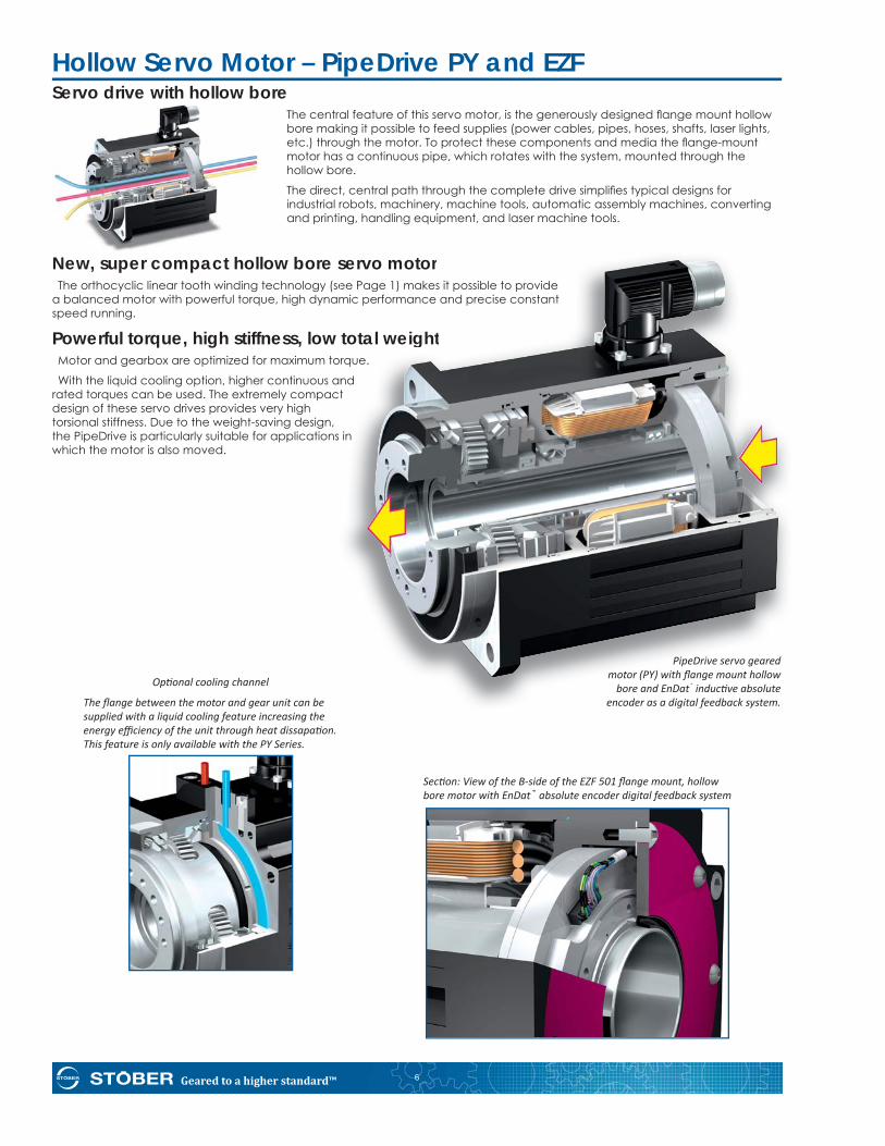
Op onal cooling channel
The fl ange between the motor and gear unit can be supplied with a liquid cooling feature increasing the energy effi ciency of the unit through heat dissapa on. This feature is only available with the PY Series.
Servo drive with hollow boreThe central feature of this servo motor, is the generously designed fl ange mount hollow bore making it possible to feed supplies (power cables, pipes, hoses, shafts, laser lights, etc.) through the motor. To protect these components and media the fl ange-mount motor has a continuous pipe, which rotates with the system, mounted through the hollow bore.
The direct, central path through the complete drive simplifi es typical designs for industrial robots, machinery, machine tools, automatic assembly machines, converting and printing, handling equipment, and laser machine tools.
New, super compact hollow bore servo motorThe orthocyclic linear tooth winding technology (see Page 1) makes it possible to provide
a balanced motor with powerful torque, high dynamic performance and precise constant speed running.
Powerful torque, high stiffness, low total weightMotor and gearbox are optimized for maximum torque.
With the liquid cooling option, higher continuous and rated torques can be used. The extremely compact design of these servo drives provides very high torsional stiffness. Due to the weight-saving design, the PipeDrive is particularly suitable for applications in which the motor is also moved.
servo motoree Page 1) makes it possible to providemic performance and precise constant
total weightrque.
ndt
in
Hollow Servo Motor – PipeDrive PY and EZF
PipeDrive servo geared motor (PY) with fl ange mount hollow
bore and EnDat® induc ve absolute encoder as a digital feedback system.
Sec on: View of the B-side of the EZF 501 fl ange mount, hollow bore motor with EnDat® absolute encoder digital feedback system
Geared to a higher standard™7
EZF – Non-geared, Flange Mount, Hollow Sha
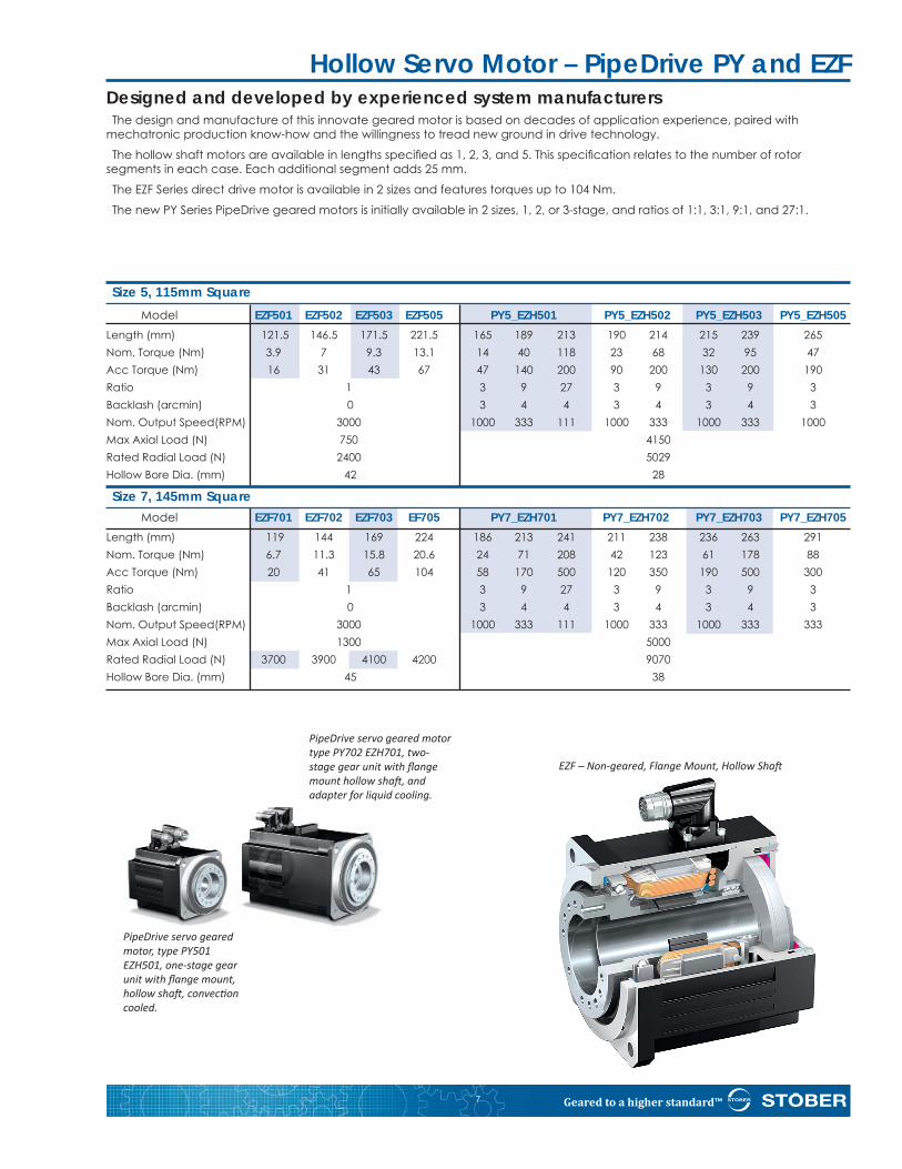
Designed and developed by experienced system manufacturersThe design and manufacture of this innovate geared motor is based on decades of application experience, paired with
mechatronic production know-how and the willingness to tread new ground in drive technology.
The hollow shaft motors are available in lengths specifi ed as 1, 2, 3, and 5. This specifi cation relates to the number of rotor segments in each case. Each additional segment adds 25 mm.
The EZF Series direct drive motor is available in 2 sizes and features torques up to 104 Nm.
The new PY Series PipeDrive geared motors is initially available in 2 sizes, 1, 2, or 3-stage, and ratios of 1:1, 3:1, 9:1, and 27:1.
Hollow Servo Motor – PipeDrive PY and EZF
PipeDrive servo geared motor type PY702 EZH701, two-stage gear unit with fl ange mount hollow sha , and adapter for liquid cooling.
PipeDrive servo geared motor, type PY501 EZH501, one-stage gear unit with fl ange mount, hollow sha , convec on cooled.
Size 5, 115mm Square Model EZF501 EZF502 EZF503 EZF505 PY5_EZH501 PY5_EZH502 PY5_EZH503 PY5_EZH505Length (mm) 121.5 146.5 171.5 221.5 165 189 213 190 214 215 239 265Nom. Torque (Nm) 3.9 7 9.3 13.1 14 40 118 23 68 32 95 47Acc Torque (Nm) 16 31 43 67 47 140 200 90 200 130 200 190Ratio 1 3 9 27 3 9 3 9 3Backlash (arcmin) 0 3 4 4 3 4 3 4 3Nom. Output Speed(RPM) 3000 1000 333 111 1000 333 1000 333 1000Max Axial Load (N) 750 4150Rated Radial Load (N) 2400 5029Hollow Bore Dia. (mm) 42 28
Size 7, 145mm Square Model EZF701 EZF702 EZF703 EF705 PY7_EZH701 PY7_EZH702 PY7_EZH703 PY7_EZH705Length (mm) 119 144 169 224 186 213 241 211 238 236 263 291Nom. Torque (Nm) 6.7 11.3 15.8 20.6 24 71 208 42 123 61 178 88Acc Torque (Nm) 20 41 65 104 58 170 500 120 350 190 500 300Ratio 1 3 9 27 3 9 3 9 3Backlash (arcmin) 0 3 4 4 3 4 3 4 3Nom. Output Speed(RPM) 3000 1000 333 111 1000 333 1000 333 333Max Axial Load (N) 1300 5000 Rated Radial Load (N) 3700 3900 4100 4200 9070Hollow Bore Dia. (mm) 45 38
Geared to a higher standard™ 8
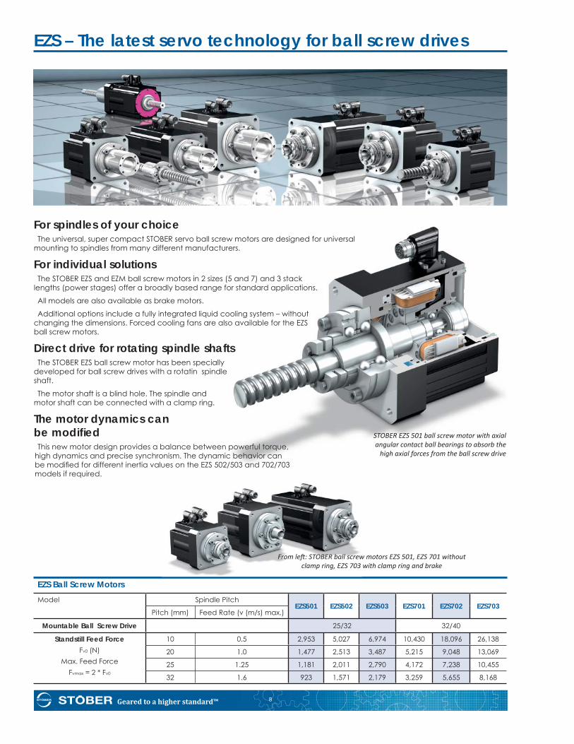
EZS – The latest servo technology for ball screw drives
EZS Ball Screw MotorsModel Spindle Pitch
EZS501 EZS502 EZS503 EZS701 EZS702 EZS703Pitch (mm) Feed Rate (v (m/s) max.)
Mountable Ball Screw Drive 25/32 32/40
Standstill Feed ForceFv0 (N)
Max. Feed ForceFvmax = 2 * Fv0
10 0.5 2,953 5,027 6,974 10,430 18,096 26,138
20 1.0 1,477 2,513 3,487 5,215 9,048 13,069
25 1.25 1,181 2,011 2,790 4,172 7,238 10,455
32 1.6 923 1,571 2,179 3,259 5,655 8,168
From le : STOBER ball screw motors EZS 501, EZS 701 without clamp ring, EZS 703 with clamp ring and brake
For spindles of your choiceThe universal, super compact STOBER servo ball screw motors are designed for universal
mounting to spindles from many different manufacturers.
For individual solutionsThe STOBER EZS and EZM ball screw motors in 2 sizes (5 and 7) and 3 stack
lengths (power stages) offer a broadly based range for standard applications.
All models are also available as brake motors.
Additional options include a fully integrated liquid cooling system – without changing the dimensions. Forced cooling fans are also available for the EZS ball screw motors.
Direct drive for rotating spindle shaftsThe STOBER EZS ball screw motor has been specially
developed for ball screw drives with a rotatin spindle shaft.
The motor shaft is a blind hole. The spindle and motor shaft can be connected with a clamp ring.
The motor dynamics can be modifi ed This new motor design provides a balance between powerful torque,
high dynamics and precise synchronism. The dynamic behavior can be modifi ed for different inertia values on the EZS 502/503 and 702/703 models if required.
STOBER EZS 501 ball screw motor with axial angular contact ball bearings to absorb the
high axial forces from the ball screw drive
Geared to a higher standard™9
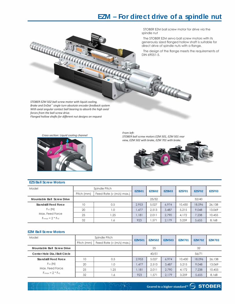
EZM – For direct drive of a spindle nutSTOBER EZM ball screw motor for drive via the
spindle nut
The STOBER EZM servo ball screw motors with its generously sized fl anged hollow shaft is suitable for direct drive of spindle nuts with a fl ange.
The design of the fl ange meets the requirements of DIN 69051-5.
Cross-sec on: Liquid cooling channel
STOBER EZM 502 ball screw motor with liquid cooling,Brake and EnDat® single turn absolute encoder feedback systemWith axial angular contact ball bearing to absorb the high axial forces from the ball screw drive.Flanged hollow sha s for diff erent nut designs on request
From le :STOBER ball screw motors EZM 501, EZM 501 rear view, EZM 502 with brake, EZM 701 with brake.
EZS Ball Screw MotorsModel Spindle Pitch
EZS501 EZS502 EZS503 EZS701 EZS702 EZS703Pitch (mm) Feed Rate (v (m/s) max.)
Mountable Ball Screw Drive 25/32 32/40
Standstill Feed ForceFv0 (N)
Max. Feed ForceFvmax = 2 * Fv0
10 0.5 2,953 5,027 6,974 10,430 18,096 26,138
20 1.0 1,477 2,513 3,487 5,215 9,048 13,069
25 1.25 1,181 2,011 2,790 4,172 7,238 10,455
32 1.6 923 1,571 2,179 3,259 5,655 8,168
EZM Ball Screw MotorsModel Spindle Pitch
EZM501 EZM502 EZM503 EZM701 EZM702 EZM703Pitch (mm) Feed Rate (v (m/s) max.)
Mountable Ball Screw Drive 25 32
Center Hole Dia./Bolt Circle 40/51 56/71
Standstill Feed ForceFv0 (N)
Max. Feed ForceFvmax = 2 * Fv0
10 0.5 2,953 5,027 6,974 10,430 18,096 26,138
20 1.0 1,477 2,513 3,487 5,215 9,048 13,069
25 1.25 1,181 2,011 2,790 4,172 7,238 10,455
32 1.6 923 1,571 2,179 3,259 5,655 8,168
Geared to a higher standard™ 10
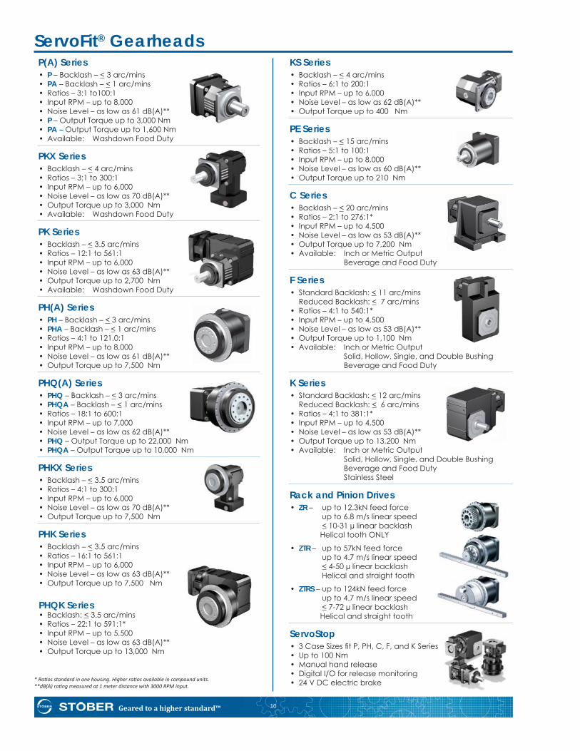
ServoFit® GearheadsP(A) Series• P – Backlash – < 3 arc/mins • PA – Backlash – < 1 arc/mins • Ratios – 3:1 to100:1 • Input RPM – up to 8,000• Noise Level – as low as 61 dB(A)**• P – Output Torque up to 3,000 Nm• PA – Output Torque up to 1,600 Nm • Available: Washdown Food Duty
PKX Series• Backlash – < 4 arc/mins • Ratios – 3:1 to 300:1• Input RPM – up to 6,000• Noise Level – as low as 70 dB(A)** • Output Torque up to 3,000 Nm• Available: Washdown Food Duty
PK Series• Backlash – < 3.5 arc/mins • Ratios – 12:1 to 561:1• Input RPM – up to 6,000• Noise Level – as low as 63 dB(A)** • Output Torque up to 2,700 Nm• Available: Washdown Food Duty
PH(A) Series• PH – Backlash – < 3 arc/mins • PHA – Backlash – < 1 arc/mins • Ratios – 4:1 to 121.0:1• Input RPM – up to 8,000• Noise Level – as low as 61 dB(A)** • Output Torque up to 7,500 Nm
PHQ(A) Series• PHQ – Backlash – < 3 arc/mins • PHQA – Backlash – < 1 arc/mins • Ratios – 18:1 to 600:1• Input RPM – up to 7,000• Noise Level – as low as 62 dB(A)** • PHQ – Output Torque up to 22,000 Nm • PHQA – Output Torque up to 10,000 Nm
PHKX Series • Backlash – < 3.5 arc/mins • Ratios – 4:1 to 300:1• Input RPM – up to 6,000• Noise Level – as low as 70 dB(A)** • Output Torque up to 7,500 Nm
PHK Series • Backlash – < 3.5 arc/mins • Ratios – 16:1 to 561:1• Input RPM – up to 6,000• Noise Level – as low as 63 dB(A)** • Output Torque up to 7,500 Nm
PHQK Series • Backlash: < 3.5 arc/mins • Ratios – 22:1 to 591:1*• Input RPM – up to 5,500• Noise Level – as low as 63 dB(A)** • Output Torque up to 13,000 Nm
* Ra os standard in one housing. Higher ra os available in compound units.**dB(A) ra ng measured at 1 meter distance with 3000 RPM input.
KS Series • Backlash – < 4 arc/mins • Ratios – 6:1 to 200:1• Input RPM – up to 6,000• Noise Level – as low as 62 dB(A)** • Output Torque up to 400 Nm
PE Series• Backlash – < 15 arc/mins • Ratios – 5:1 to 100:1• Input RPM – up to 8,000• Noise Level – as low as 60 dB(A)** • Output Torque up to 210 Nm
C Series• Backlash – < 20 arc/mins • Ratios – 2:1 to 276:1*• Input RPM – up to 4,500• Noise Level – as low as 53 dB(A)** • Output Torque up to 7,200 Nm• Available: Inch or Metric Output Beverage and Food Duty
F Series• Standard Backlash: < 11 arc/mins Reduced Backlash: < 7 arc/mins • Ratios – 4:1 to 540:1*• Input RPM – up to 4,500• Noise Level – as low as 53 dB(A)** • Output Torque up to 1,100 Nm• Available: Inch or Metric Output Solid, Hollow, Single, and Double Bushing Beverage and Food Duty
K Series • Standard Backlash: < 12 arc/mins Reduced Backlash: < 6 arc/mins • Ratios – 4:1 to 381:1*• Input RPM – up to 4,500• Noise Level – as low as 53 dB(A)** • Output Torque up to 13,200 Nm • Available: Inch or Metric Output Solid, Hollow, Single, and Double Bushing Beverage and Food Duty Stainless Steel
Rack and Pinion Drives • ZR – up to 12.3kN feed force up to 6.8 m/s linear speed < 10-31 μ linear backlash Helical tooth ONLY
• ZTR – up to 57kN feed force up to 4.7 m/s linear speed < 4-50 μ linear backlash Helical and straight tooth
• ZTRS – up to 124kN feed force up to 4.7 m/s linear speed < 7-72 μ linear backlash Helical and straight tooth
ServoStop • 3 Case Sizes fi t P, PH, C, F, and K Series • Up to 100 Nm• Manual hand release• Digital I/O for release monitoring• 24 V DC electric brake
Geared to a higher standard™11
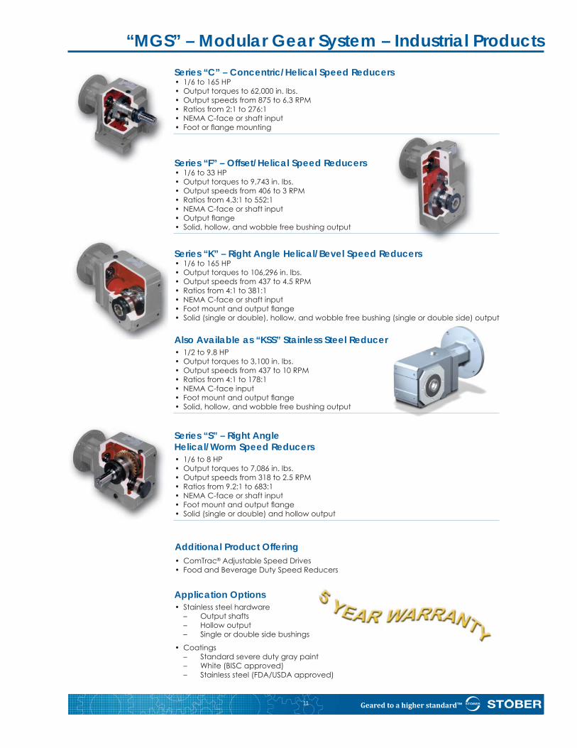
Series “C” – Concentric/Helical Speed Reducers• 1/6 to 165 HP• Output torques to 62,000 in. lbs.• Output speeds from 875 to 6.3 RPM• Ratios from 2:1 to 276:1• NEMA C-face or shaft input• Foot or fl ange mounting
Series “F” – Offset/Helical Speed Reducers• 1/6 to 33 HP• Output torques to 9,743 in. lbs.• Output speeds from 406 to 3 RPM• Ratios from 4.3:1 to 552:1• NEMA C-face or shaft input• Output fl ange• Solid, hollow, and wobble free bushing output
Series “K” – Right Angle Helical/Bevel Speed Reducers• 1/6 to 165 HP• Output torques to 106,296 in. lbs.• Output speeds from 437 to 4.5 RPM• Ratios from 4:1 to 381:1• NEMA C-face or shaft input• Foot mount and output fl ange• Solid (single or double), hollow, and wobble free bushing (single or double side) output
Also Available as “KSS” Stainless Steel Reducer• 1/2 to 9.8 HP• Output torques to 3,100 in. lbs.• Output speeds from 437 to 10 RPM• Ratios from 4:1 to 178:1• NEMA C-face input• Foot mount and output fl ange• Solid, hollow, and wobble free bushing output
Series “S” – Right AngleHelical/Worm Speed Reducers• 1/6 to 8 HP• Output torques to 7,086 in. lbs.• Output speeds from 318 to 2.5 RPM• Ratios from 9.2:1 to 683:1• NEMA C-face or shaft input• Foot mount and output fl ange• Solid (single or double) and hollow output
Additional Product Offering• ComTrac® Adjustable Speed Drives • Food and Beverage Duty Speed Reducers
Application Options• Stainless steel hardware – Output shafts – Hollow output – Single or double side bushings
• Coatings – Standard severe duty gray paint – White (BISC approved) – Stainless steel (FDA/USDA approved)dditional
“MGS” – Modular Gear System – Industrial Products
Geared to a higher standard™ 12
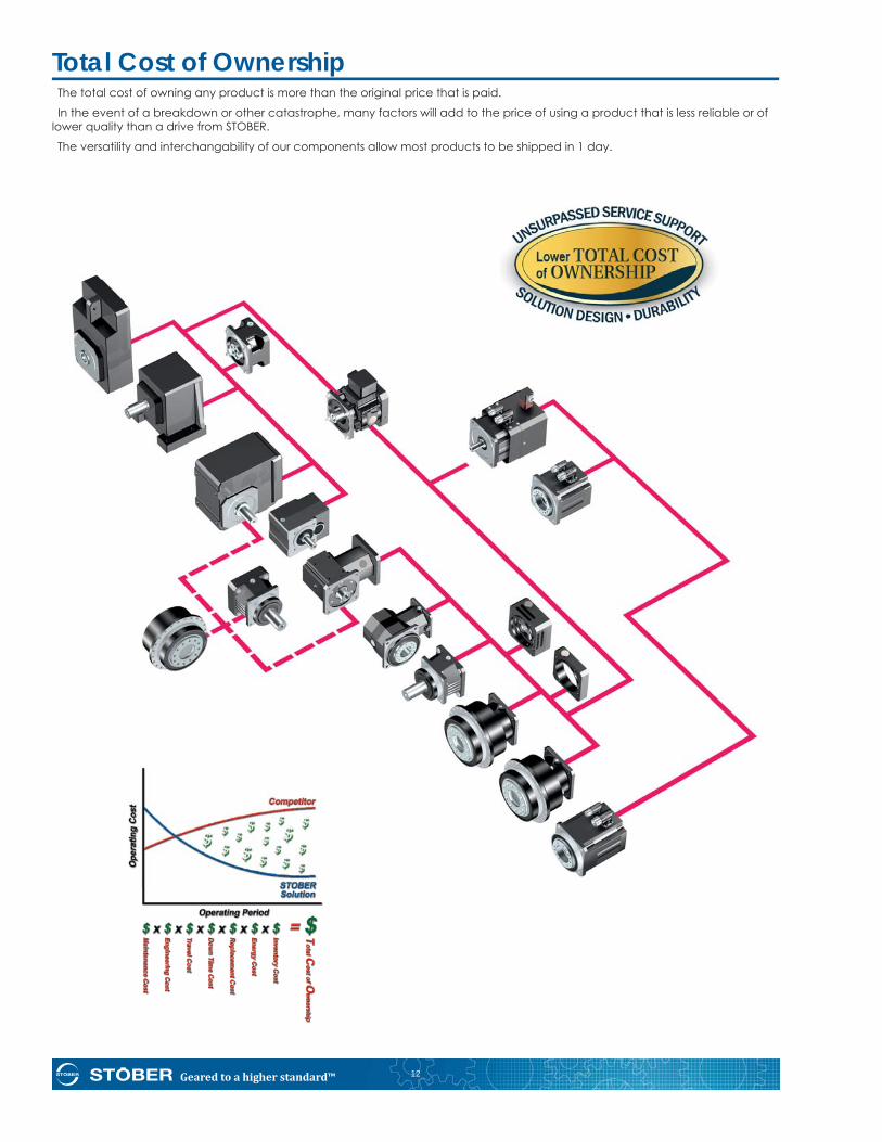
Total Cost of OwnershipThe total cost of owning any product is more than the original price that is paid.
In the event of a breakdown or other catastrophe, many factors will add to the price of using a product that is less reliable or of lower quality than a drive from STOBER.
The versatility and interchangability of our components allow most products to be shipped in 1 day.
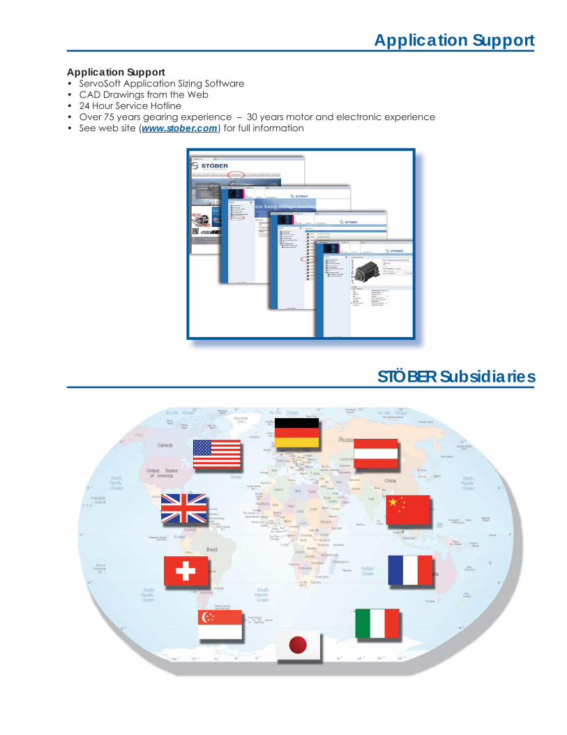
Application Support
Application Support• ServoSoft Application Sizing Software• CAD Drawings from the Web• 24 Hour Service Hotline• Over 75 years gearing experience – 30 years motor and electronic experience• See web site (www.stober.com) for full information
STÖBER Subsidiaries


![Mascn Ccunty Reading Plan. INSTITUTICN Mascn … County Schools, Maysville, Ky. [6E] 37p. EDES Price ME-$0.25. Grade 7, Grade 8, *Grade Crganizaticn, *Grouping (Instructional Purposes),](https://img.pdfslide.us/doc/110x75/5af77d247f8b9a927191b7f1/mascn-ccunty-reading-plan-instituticn-mascn-county-schools-maysville-ky.jpg)