Embed Size (px)
Citation preview
November 2009 Doc ID 13916 Rev 7 1/25
UM0462User manual
STM32™ and STM8™Flash loader demonstrator
IntroductionThe purpose of this document is to describe the STMicroelectronics STM32™ and STM8™ Flash loader demonstrator application that was developed to illustrate the System memory boot loader capabilities.
This document details the prerequested hardware and software environments, as well as the use cases of the demonstrator software.
www.st.com
Contents UM0462
2/25 Doc ID 13916 Rev 7
Contents
1 Getting started . . . . . . . . . . . . . . . . . . . . . . . . . . . . . . . . . . . . . . . . . . . . . . 5
1.1 Package contents . . . . . . . . . . . . . . . . . . . . . . . . . . . . . . . . . . . . . . . . . . . . 5
1.1.1 Software contents . . . . . . . . . . . . . . . . . . . . . . . . . . . . . . . . . . . . . . . . . . 5
1.1.2 Hardware contents . . . . . . . . . . . . . . . . . . . . . . . . . . . . . . . . . . . . . . . . . . 5
1.2 System requirements . . . . . . . . . . . . . . . . . . . . . . . . . . . . . . . . . . . . . . . . . 5
1.3 Flash loader demonstrator installation . . . . . . . . . . . . . . . . . . . . . . . . . . . . 7
1.3.1 Software installation . . . . . . . . . . . . . . . . . . . . . . . . . . . . . . . . . . . . . . . . . 7
1.3.2 Hardware installation . . . . . . . . . . . . . . . . . . . . . . . . . . . . . . . . . . . . . . . . 9
2 User interface description . . . . . . . . . . . . . . . . . . . . . . . . . . . . . . . . . . . 10
3 Command-line usage . . . . . . . . . . . . . . . . . . . . . . . . . . . . . . . . . . . . . . . 20
4 Revision history . . . . . . . . . . . . . . . . . . . . . . . . . . . . . . . . . . . . . . . . . . . 24
UM0462 List of tables
Doc ID 13916 Rev 7 3/25
List of tables
Table 1. Document revision history . . . . . . . . . . . . . . . . . . . . . . . . . . . . . . . . . . . . . . . . . . . . . . . . . 24
List of figures UM0462
4/25 Doc ID 13916 Rev 7
List of figures
Figure 1. System Properties dialog box . . . . . . . . . . . . . . . . . . . . . . . . . . . . . . . . . . . . . . . . . . . . . . . . 6Figure 2. Device Manager window. . . . . . . . . . . . . . . . . . . . . . . . . . . . . . . . . . . . . . . . . . . . . . . . . . . . 7Figure 3. InstallShield Wizard . . . . . . . . . . . . . . . . . . . . . . . . . . . . . . . . . . . . . . . . . . . . . . . . . . . . . . . 8Figure 4. InstallShield Wizard license agreement . . . . . . . . . . . . . . . . . . . . . . . . . . . . . . . . . . . . . . . . 8Figure 5. Connection settings page . . . . . . . . . . . . . . . . . . . . . . . . . . . . . . . . . . . . . . . . . . . . . . . . . . 11Figure 6. Flash status page . . . . . . . . . . . . . . . . . . . . . . . . . . . . . . . . . . . . . . . . . . . . . . . . . . . . . . . . 12Figure 7. Device information page - STM32 example . . . . . . . . . . . . . . . . . . . . . . . . . . . . . . . . . . . . 13Figure 8. Device information page - STM8 example . . . . . . . . . . . . . . . . . . . . . . . . . . . . . . . . . . . . . 14Figure 9. Operation choice page for STM32 . . . . . . . . . . . . . . . . . . . . . . . . . . . . . . . . . . . . . . . . . . . 16Figure 10. Operation choice page for STM8 . . . . . . . . . . . . . . . . . . . . . . . . . . . . . . . . . . . . . . . . . . . . 17Figure 11. Option byte edition page. . . . . . . . . . . . . . . . . . . . . . . . . . . . . . . . . . . . . . . . . . . . . . . . . . . 18Figure 12. Operation progress page . . . . . . . . . . . . . . . . . . . . . . . . . . . . . . . . . . . . . . . . . . . . . . . . . . 19Figure 13. Command-line version . . . . . . . . . . . . . . . . . . . . . . . . . . . . . . . . . . . . . . . . . . . . . . . . . . . . 20
UM0462 Getting started
Doc ID 13916 Rev 7 5/25
1 Getting started
1.1 Package contentsThe following items are supplied in the Flash loader demonstrator package:
1.1.1 Software contents
1. STBLLIB.dll: a dynamic-link library implementing the system memory boot loader protocol and the communication APIs as virtual functions to be loaded dynamically from the STUARTBLLib dll file.
2. STUARTBLLib.dll: a dynamic-link library implementing the system memory boot loader protocol and the RS232 COM communication APIs.
3. Files.dll: a dynamic-link library implementing the needed file manipulation APIs to load and store binary, hexadecimal and motorola S19 files.
4. STMicroelectronics Flash loader.exe: a wizard application that provides the high-level operations that can be performed by the user.
5. STMFlashLoader.exe: a command-line version of the STMicroelectronics Flash loader.exe that provides the same features over several options.
6. The “Map” directory is located in the installation directory. It contains the mapping description files of the supported devices.
7. The “Src” directory is located in the installation directory. It contains the header and Lib files of the two DLLs and the complete source of the command-line version.
8. The “Doc” directory is located in the installation directory, it contains the UM0462 and UM0516 (Windows API for STMicroelectronics microcontroller boot loaders) user manuals.
1.1.2 Hardware contents
The Flash loader demonstrator is designed to work with all STMicroelectronics devices that support the system memory boot mode UART protocol. For more details, please visit the STMicroelectronics website (http://www.st.com).
1.2 System requirementsIn order to use the Flash loader demonstrator with the Windows operating system, a recent version of Windows, such as Windows 98, Millennium, 2000, XP, Vista or Windows7 must be installed on the PC.
The version of the Windows OS installed on your computer may be determined by right-clicking on the “My Computer” icon on the desktop, then clicking on the “Properties” item in the displayed pop-up menu. The OS type is displayed in the “System Properties” dialog box under the “System” label as shown in Figure 1.
Getting started UM0462
6/25 Doc ID 13916 Rev 7
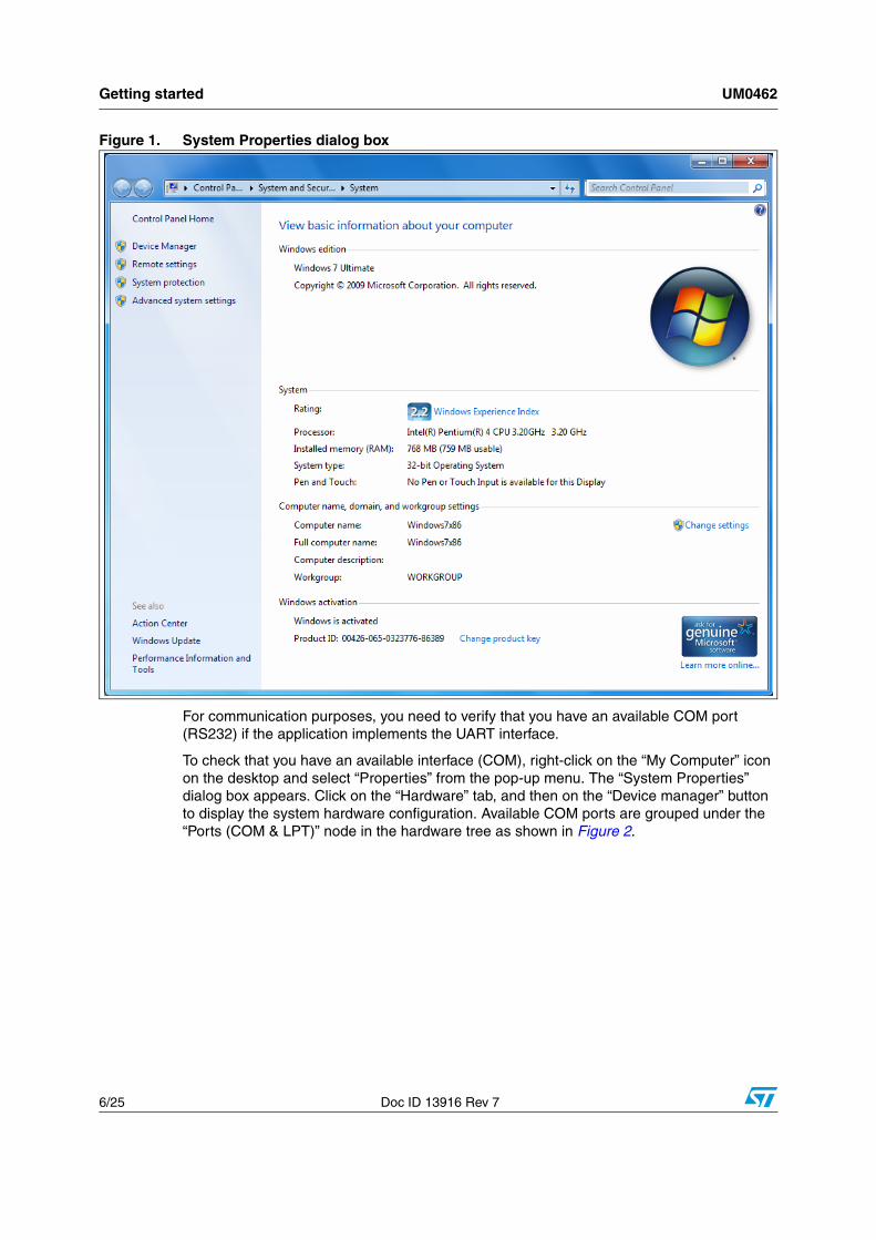
Figure 1. System Properties dialog box
For communication purposes, you need to verify that you have an available COM port (RS232) if the application implements the UART interface.
To check that you have an available interface (COM), right-click on the “My Computer” icon on the desktop and select “Properties” from the pop-up menu. The “System Properties” dialog box appears. Click on the “Hardware” tab, and then on the “Device manager” button to display the system hardware configuration. Available COM ports are grouped under the “Ports (COM & LPT)” node in the hardware tree as shown in Figure 2.
UM0462 Getting started
Doc ID 13916 Rev 7 7/25
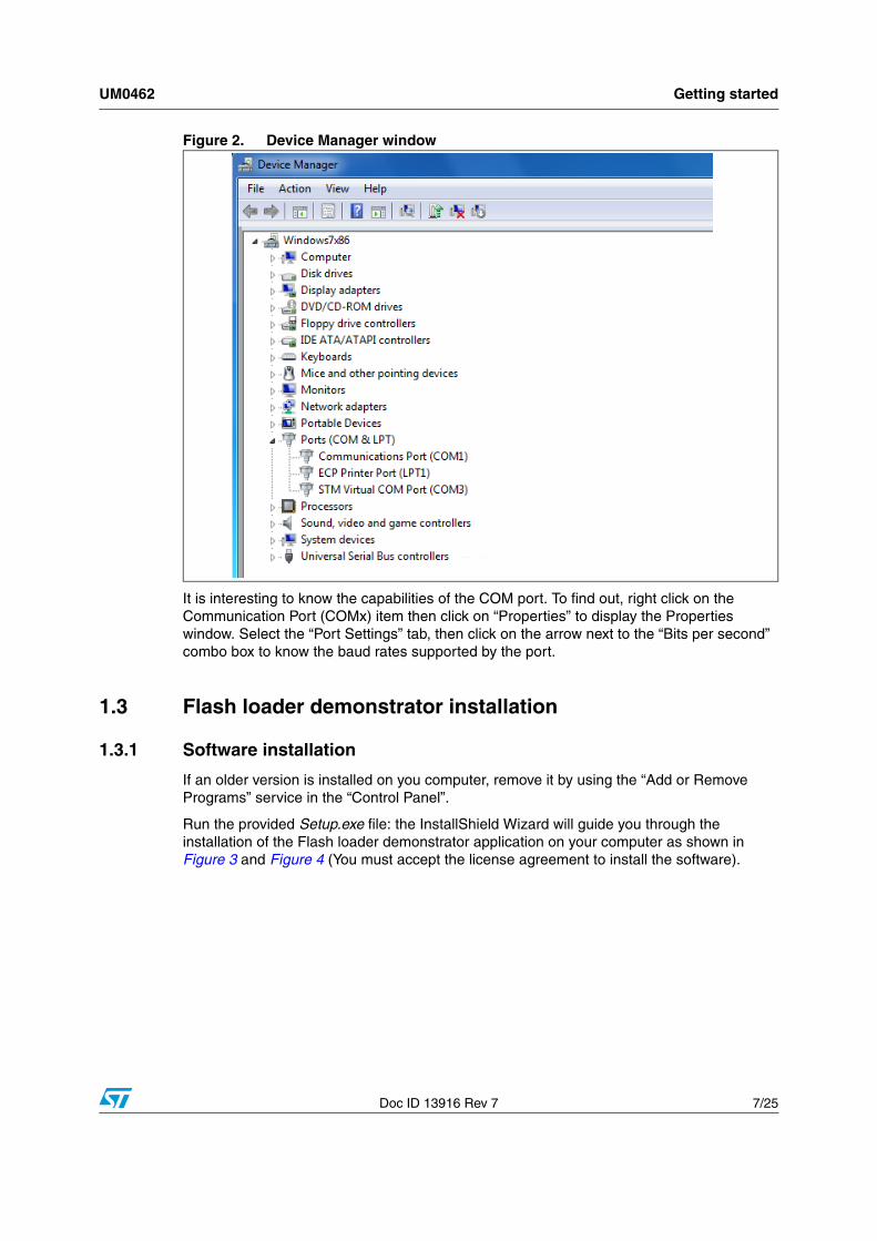
Figure 2. Device Manager window
It is interesting to know the capabilities of the COM port. To find out, right click on the Communication Port (COMx) item then click on “Properties” to display the Properties window. Select the “Port Settings” tab, then click on the arrow next to the “Bits per second” combo box to know the baud rates supported by the port.
1.3 Flash loader demonstrator installation
1.3.1 Software installation
If an older version is installed on you computer, remove it by using the “Add or Remove Programs” service in the “Control Panel”.
Run the provided Setup.exe file: the InstallShield Wizard will guide you through the installation of the Flash loader demonstrator application on your computer as shown in Figure 3 and Figure 4 (You must accept the license agreement to install the software).
Getting started UM0462
8/25 Doc ID 13916 Rev 7
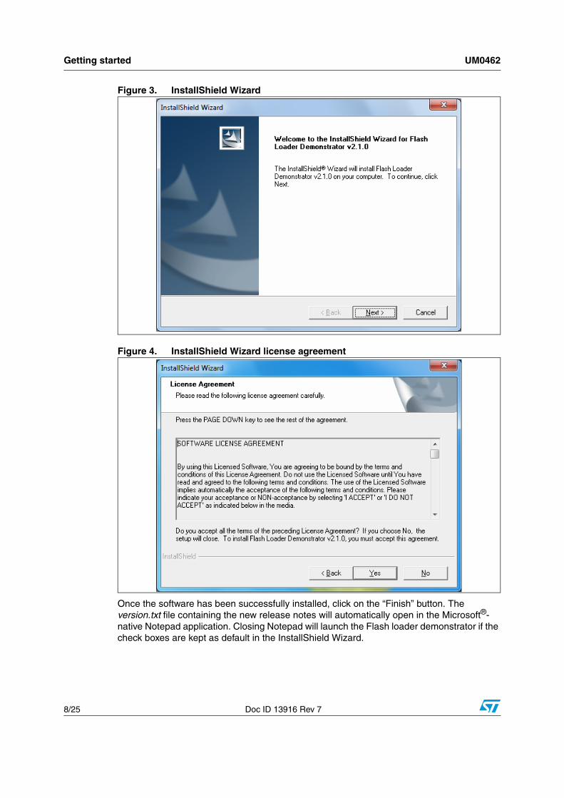
Figure 3. InstallShield Wizard
Figure 4. InstallShield Wizard license agreement
Once the software has been successfully installed, click on the “Finish” button. The version.txt file containing the new release notes will automatically open in the Microsoft®-native Notepad application. Closing Notepad will launch the Flash loader demonstrator if the check boxes are kept as default in the InstallShield Wizard.
UM0462 Getting started
Doc ID 13916 Rev 7 9/25
1.3.2 Hardware installation
As the Flash loader demonstrator is able to communicate over the UART interface, the device should be connected to a spare PC COM port in the event of a UART communication.
User interface description UM0462
10/25 Doc ID 13916 Rev 7
2 User interface description
The Flash loader demonstrator is designed as a wizard application. It is structured into six steps, the:
1. Connection settings page
2. Flash status page
3. Device information page
4. Operation choice page
5. Option byte edition page
6. Operation progress page
Step 1
Run the Flash loader demonstrator application from the “Programs” menu (connection to the device has not been made yet) then, make sure that the device is connected to your PC and reset it to restart the system memory boot loader code.
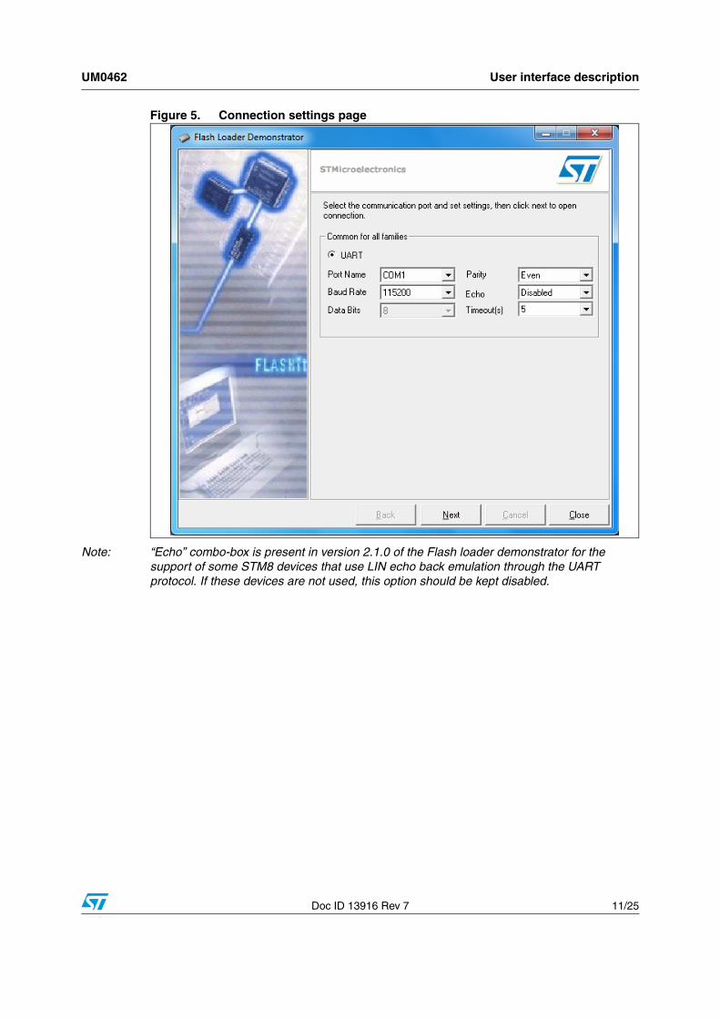
This step consists in selecting the UART connection interface and its related settings. Set the connection settings (port name, baud rate and timeout, etc.) as shown in Figure 5. For an optimum configuration for the UART interface, set “Baud Rate” to 115200 bits per second and “Timeout(s)” to 5 seconds.
Ensure that the boot configuration pins are set correctly, then click “Next” to continue. If a connection has been established, the wizard moves to the next step, otherwise a message box is displayed that indicates the error that occurred.
Possible errors messages:
● “Cannot open the COM port”: this message is shown if the selected COM port is not found or if it is already being used by another process.
● “Unrecognized device”: this message is shown if the received value is different from 0x79. Resetting the device may solve the problem.
● “No response from the target”: this message is shown when there is no response from the target. It indicates that the System memory boot loader is not functional. Verify the boot configuration and check that the used microcontroller contains the boot loader code.
Note: The Timeout argument is the period of time after which a read request from the serial port is aborted if no data is received. The recommended value is 5 seconds, but it depends on the used environment, like the hardware performance.
UM0462 User interface description
Doc ID 13916 Rev 7 11/25
Figure 5. Connection settings page
Note: “Echo” combo-box is present in version 2.1.0 of the Flash loader demonstrator for the support of some STM8 devices that use LIN echo back emulation through the UART protocol. If these devices are not used, this option should be kept disabled.
User interface description UM0462
12/25 Doc ID 13916 Rev 7
Step 2
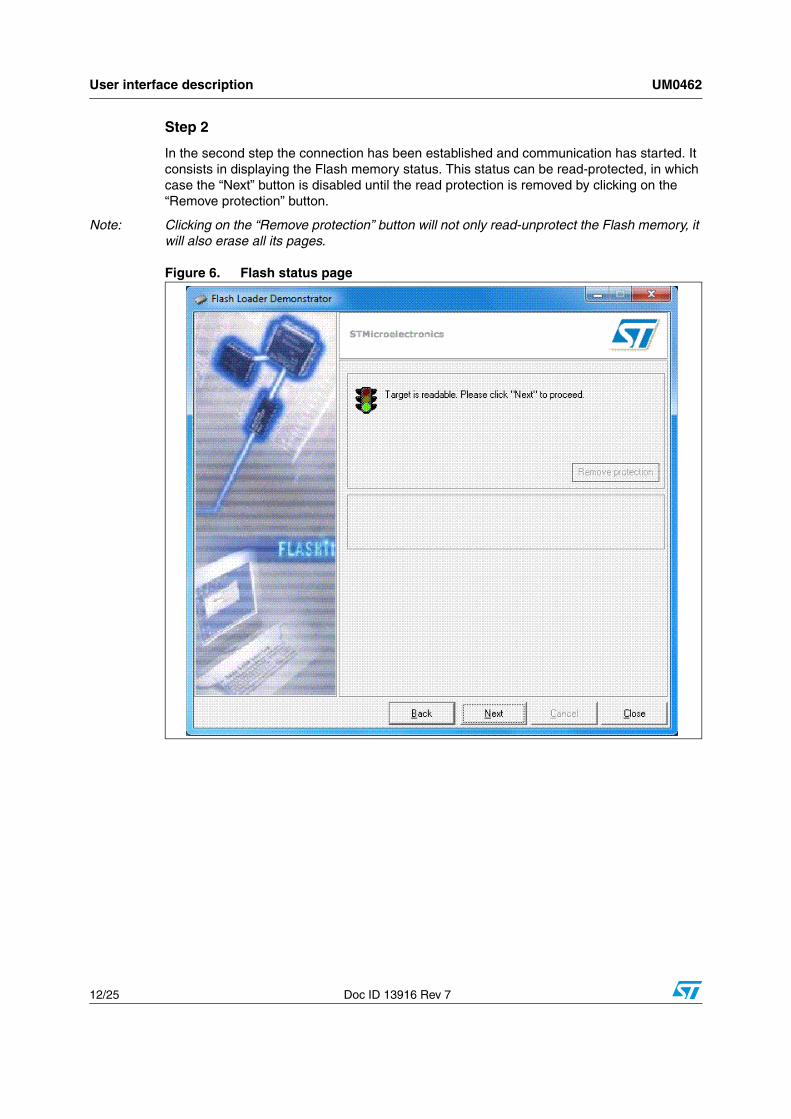
In the second step the connection has been established and communication has started. It consists in displaying the Flash memory status. This status can be read-protected, in which case the “Next” button is disabled until the read protection is removed by clicking on the “Remove protection” button.
Note: Clicking on the “Remove protection” button will not only read-unprotect the Flash memory, it will also erase all its pages.
Figure 6. Flash status page
UM0462 User interface description
Doc ID 13916 Rev 7 13/25
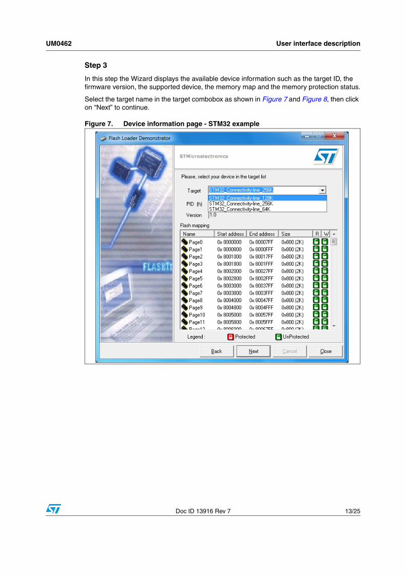
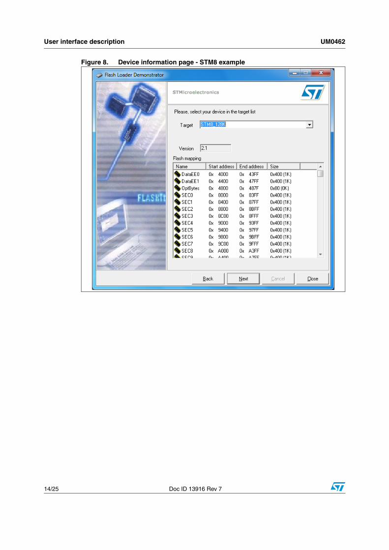
Step 3
In this step the Wizard displays the available device information such as the target ID, the firmware version, the supported device, the memory map and the memory protection status.
Select the target name in the target combobox as shown in Figure 7 and Figure 8, then click on “Next” to continue.
Figure 7. Device information page - STM32 example
User interface description UM0462
14/25 Doc ID 13916 Rev 7
Figure 8. Device information page - STM8 example
UM0462 User interface description
Doc ID 13916 Rev 7 15/25
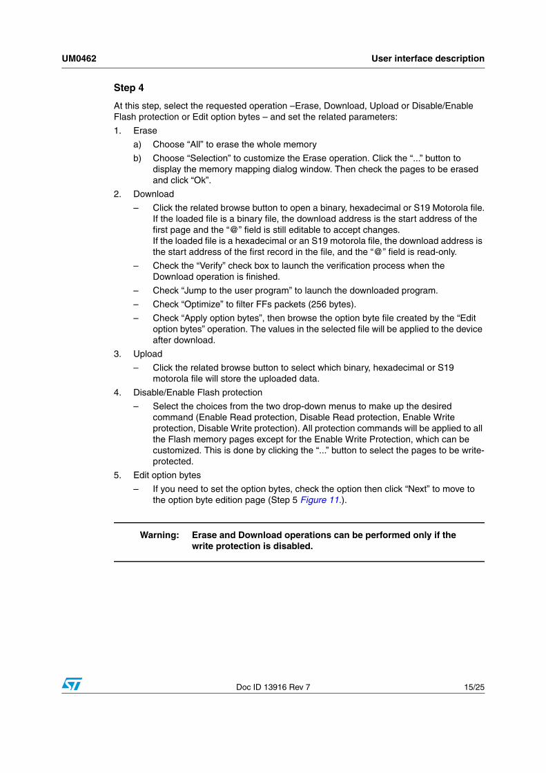
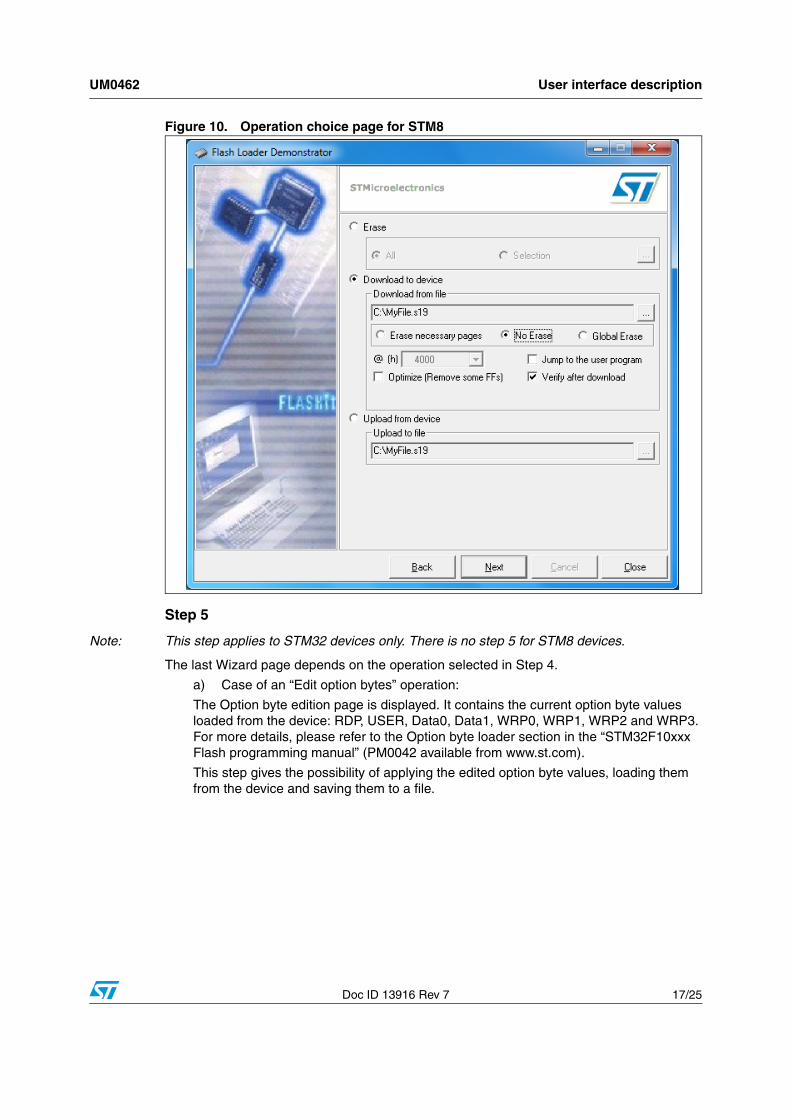
Step 4
At this step, select the requested operation –Erase, Download, Upload or Disable/Enable Flash protection or Edit option bytes – and set the related parameters:
1. Erase
a) Choose “All” to erase the whole memory
b) Choose “Selection” to customize the Erase operation. Click the “...” button to display the memory mapping dialog window. Then check the pages to be erased and click “Ok”.
2. Download
– Click the related browse button to open a binary, hexadecimal or S19 Motorola file.If the loaded file is a binary file, the download address is the start address of the first page and the “@” field is still editable to accept changes.If the loaded file is a hexadecimal or an S19 motorola file, the download address is the start address of the first record in the file, and the “@” field is read-only.
– Check the “Verify” check box to launch the verification process when the Download operation is finished.
– Check “Jump to the user program” to launch the downloaded program.
– Check “Optimize” to filter FFs packets (256 bytes).
– Check “Apply option bytes”, then browse the option byte file created by the “Edit option bytes” operation. The values in the selected file will be applied to the device after download.
3. Upload
– Click the related browse button to select which binary, hexadecimal or S19 motorola file will store the uploaded data.
4. Disable/Enable Flash protection
– Select the choices from the two drop-down menus to make up the desired command (Enable Read protection, Disable Read protection, Enable Write protection, Disable Write protection). All protection commands will be applied to all the Flash memory pages except for the Enable Write Protection, which can be customized. This is done by clicking the “...” button to select the pages to be write-protected.
5. Edit option bytes
– If you need to set the option bytes, check the option then click “Next” to move to the option byte edition page (Step 5 Figure 11.).
Warning: Erase and Download operations can be performed only if the write protection is disabled.
User interface description UM0462
16/25 Doc ID 13916 Rev 7
Figure 9. Operation choice page for STM32
UM0462 User interface description
Doc ID 13916 Rev 7 17/25
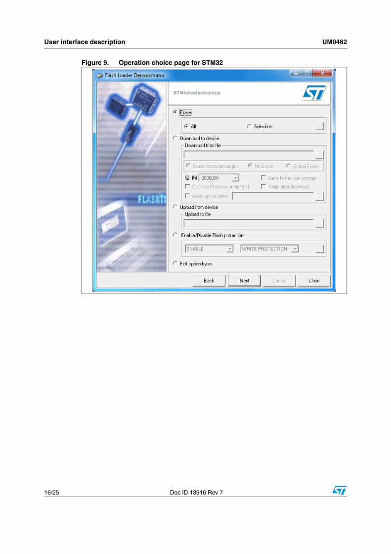
Figure 10. Operation choice page for STM8
Step 5
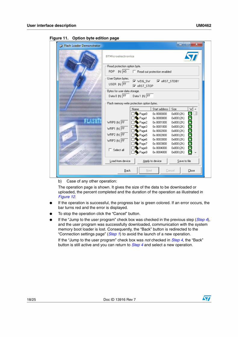
Note: This step applies to STM32 devices only. There is no step 5 for STM8 devices.
The last Wizard page depends on the operation selected in Step 4.
a) Case of an “Edit option bytes” operation:
The Option byte edition page is displayed. It contains the current option byte values loaded from the device: RDP, USER, Data0, Data1, WRP0, WRP1, WRP2 and WRP3. For more details, please refer to the Option byte loader section in the “STM32F10xxx Flash programming manual” (PM0042 available from www.st.com).
This step gives the possibility of applying the edited option byte values, loading them from the device and saving them to a file.
User interface description UM0462
18/25 Doc ID 13916 Rev 7
Figure 11. Option byte edition page
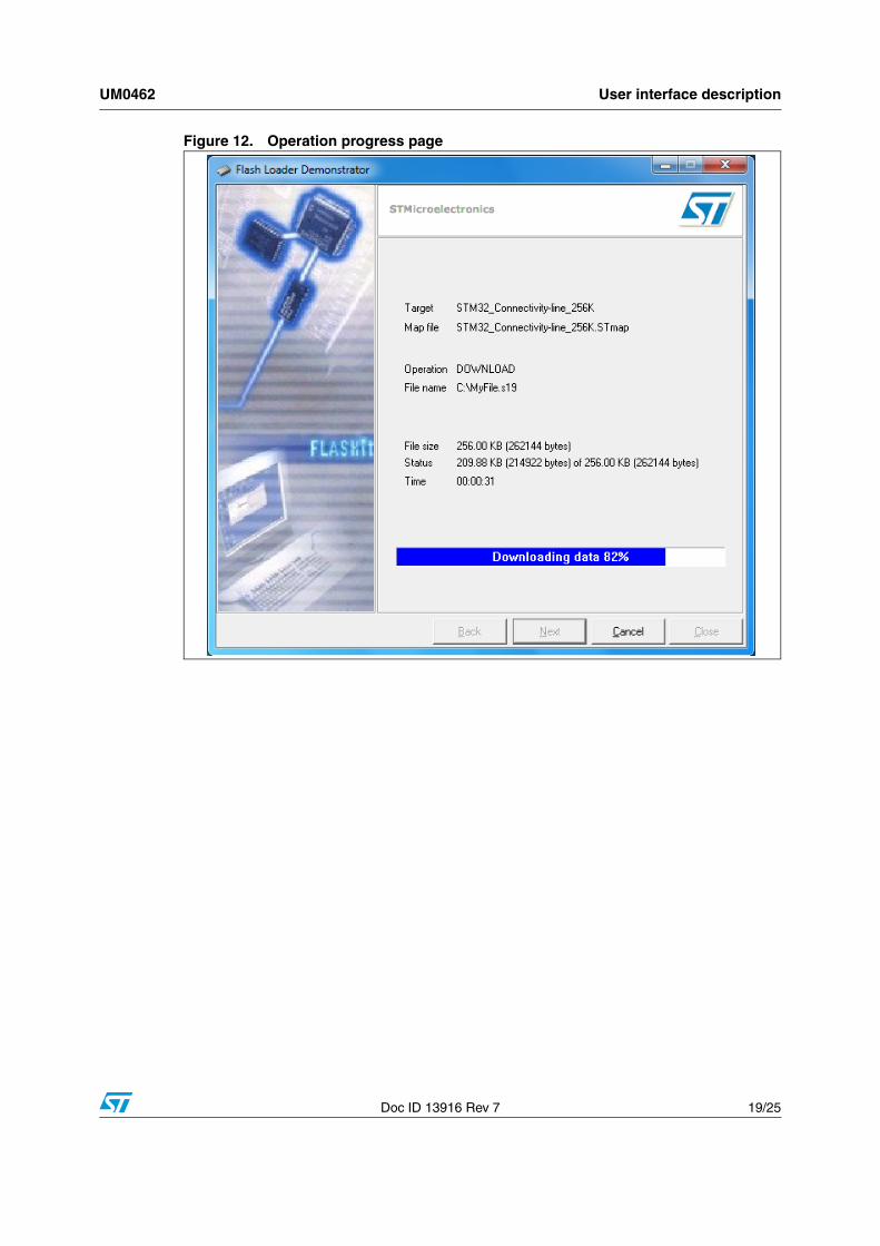
b) Case of any other operation:
The operation page is shown. It gives the size of the data to be downloaded or uploaded, the percent completed and the duration of the operation as illustrated in Figure 12.
● If the operation is successful, the progress bar is green colored. If an error occurs, the bar turns red and the error is displayed.
● To stop the operation click the “Cancel” button.
● If the “Jump to the user program” check box was checked in the previous step (Step 4), and the user program was successfully downloaded, communication with the system memory boot loader is lost. Consequently, the “Back” button is redirected to the “Connection settings page” (Step 1) to avoid the launch of a new operation.
If the “Jump to the user program” check box was not checked in Step 4, the “Back” button is still active and you can return to Step 4 and select a new operation.
UM0462 User interface description
Doc ID 13916 Rev 7 19/25
Figure 12. Operation progress page
Command-line usage UM0462
20/25 Doc ID 13916 Rev 7
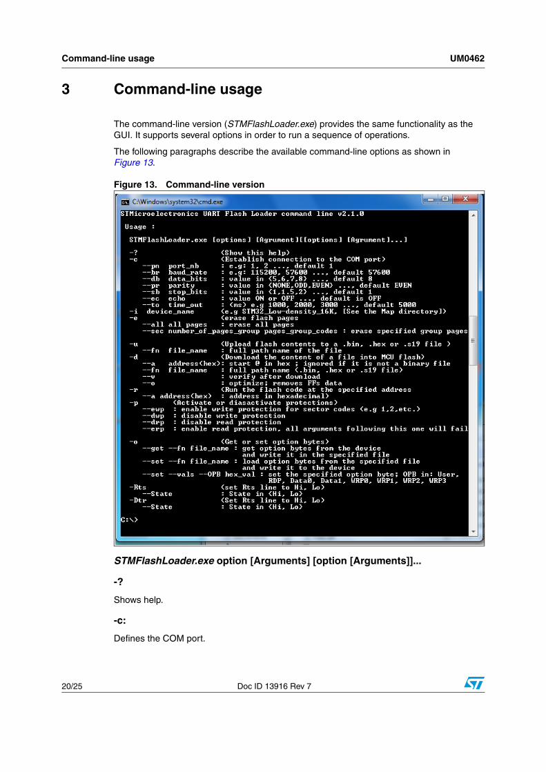
3 Command-line usage
The command-line version (STMFlashLoader.exe) provides the same functionality as the GUI. It supports several options in order to run a sequence of operations.
The following paragraphs describe the available command-line options as shown in Figure 13.
Figure 13. Command-line version
STMFlashLoader.exe option [Arguments] [option [Arguments]]...
-?
Shows help.
-c:
Defines the COM port.
UM0462 Command-line usage
Doc ID 13916 Rev 7 21/25
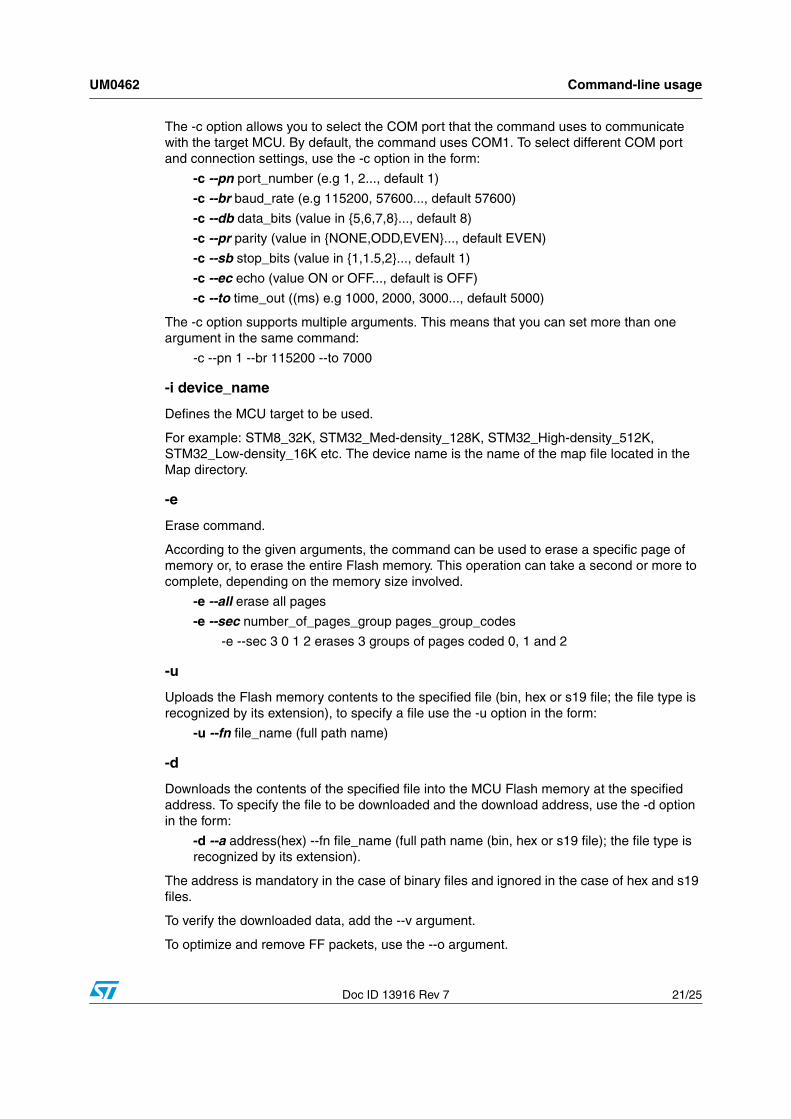
The -c option allows you to select the COM port that the command uses to communicate with the target MCU. By default, the command uses COM1. To select different COM port and connection settings, use the -c option in the form:
-c --pn port_number (e.g 1, 2..., default 1)
-c --br baud_rate (e.g 115200, 57600..., default 57600)
-c --db data_bits (value in {5,6,7,8}..., default 8)
-c --pr parity (value in {NONE,ODD,EVEN}..., default EVEN)
-c --sb stop_bits (value in {1,1.5,2}..., default 1)
-c --ec echo (value ON or OFF..., default is OFF)
-c --to time_out ((ms) e.g 1000, 2000, 3000..., default 5000)
The -c option supports multiple arguments. This means that you can set more than one argument in the same command:
-c --pn 1 --br 115200 --to 7000
-i device_name
Defines the MCU target to be used.
For example: STM8_32K, STM32_Med-density_128K, STM32_High-density_512K, STM32_Low-density_16K etc. The device name is the name of the map file located in the Map directory.
-e
Erase command.
According to the given arguments, the command can be used to erase a specific page of memory or, to erase the entire Flash memory. This operation can take a second or more to complete, depending on the memory size involved.
-e --all erase all pages
-e --sec number_of_pages_group pages_group_codes
-e --sec 3 0 1 2 erases 3 groups of pages coded 0, 1 and 2
-u
Uploads the Flash memory contents to the specified file (bin, hex or s19 file; the file type is recognized by its extension), to specify a file use the -u option in the form:
-u --fn file_name (full path name)
-d
Downloads the contents of the specified file into the MCU Flash memory at the specified address. To specify the file to be downloaded and the download address, use the -d option in the form:
-d --a address(hex) --fn file_name (full path name (bin, hex or s19 file); the file type is recognized by its extension).
The address is mandatory in the case of binary files and ignored in the case of hex and s19 files.
To verify the downloaded data, add the --v argument.
To optimize and remove FF packets, use the --o argument.
Command-line usage UM0462
22/25 Doc ID 13916 Rev 7
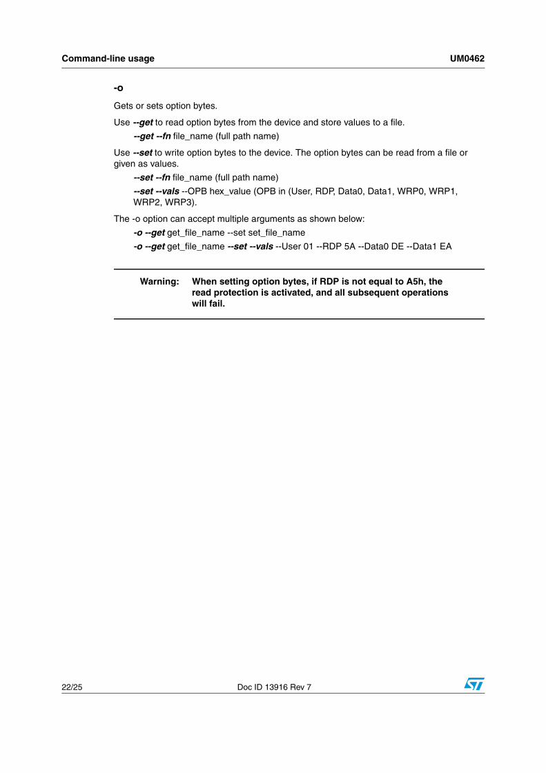
-o
Gets or sets option bytes.
Use --get to read option bytes from the device and store values to a file.
--get --fn file_name (full path name)
Use --set to write option bytes to the device. The option bytes can be read from a file or given as values.
--set --fn file_name (full path name)
--set --vals --OPB hex_value (OPB in (User, RDP, Data0, Data1, WRP0, WRP1, WRP2, WRP3).
The -o option can accept multiple arguments as shown below:
-o --get get_file_name --set set_file_name
-o --get get_file_name --set --vals --User 01 --RDP 5A --Data0 DE --Data1 EA
Warning: When setting option bytes, if RDP is not equal to A5h, the read protection is activated, and all subsequent operations will fail.
UM0462 Command-line usage
Doc ID 13916 Rev 7 23/25
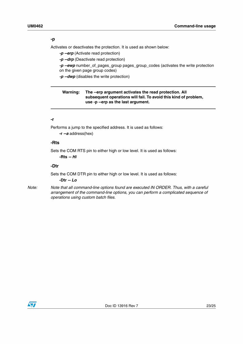
-p
Activates or deactivates the protection. It is used as shown below:
-p --erp (Activate read protection)
-p --drp (Deactivate read protection)
-p --ewp number_of_pages_group pages_group_codes (activates the write protection on the given page group codes)
-p --dwp (disables the write protection)
Warning: The --erp argument activates the read protection. All subsequent operations will fail. To avoid this kind of problem, use -p --erp as the last argument.
-r
Performs a jump to the specified address. It is used as follows:
-r --a address(hex)
-Rts
Sets the COM RTS pin to either high or low level. It is used as follows:
-Rts -- Hi
-Dtr
Sets the COM DTR pin to either high or low level. It is used as follows:
-Dtr -- Lo
Note: Note that all command-line options found are executed IN ORDER. Thus, with a careful arrangement of the command-line options, you can perform a complicated sequence of operations using custom batch files.
Revision history UM0462
24/25 Doc ID 13916 Rev 7
4 Revision history
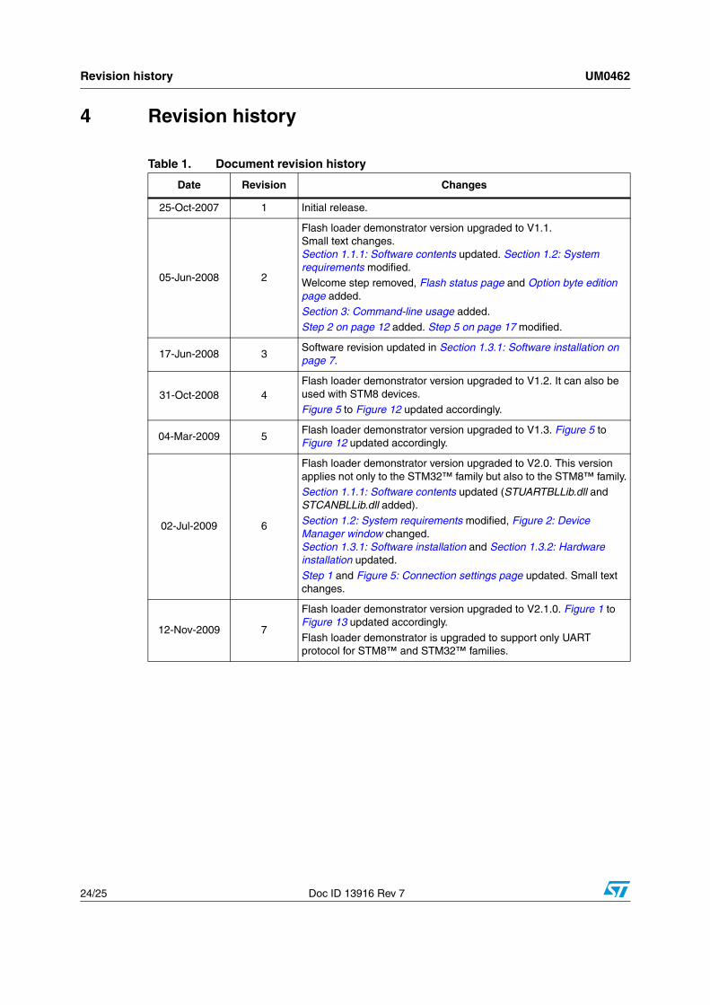
Table 1. Document revision history
Date Revision Changes
25-Oct-2007 1 Initial release.
05-Jun-2008 2
Flash loader demonstrator version upgraded to V1.1.Small text changes.Section 1.1.1: Software contents updated. Section 1.2: System requirements modified.Welcome step removed, Flash status page and Option byte edition page added.Section 3: Command-line usage added.
Step 2 on page 12 added. Step 5 on page 17 modified.
17-Jun-2008 3Software revision updated in Section 1.3.1: Software installation on page 7.
31-Oct-2008 4Flash loader demonstrator version upgraded to V1.2. It can also be used with STM8 devices.Figure 5 to Figure 12 updated accordingly.
04-Mar-2009 5Flash loader demonstrator version upgraded to V1.3. Figure 5 to Figure 12 updated accordingly.
02-Jul-2009 6
Flash loader demonstrator version upgraded to V2.0. This version applies not only to the STM32™ family but also to the STM8™ family.Section 1.1.1: Software contents updated (STUARTBLLib.dll and STCANBLLib.dll added).Section 1.2: System requirements modified, Figure 2: Device Manager window changed.Section 1.3.1: Software installation and Section 1.3.2: Hardware installation updated.
Step 1 and Figure 5: Connection settings page updated. Small text changes.
12-Nov-2009 7
Flash loader demonstrator version upgraded to V2.1.0. Figure 1 to Figure 13 updated accordingly.
Flash loader demonstrator is upgraded to support only UART protocol for STM8™ and STM32™ families.
UM0462
Doc ID 13916 Rev 7 25/25
Please Read Carefully:
Information in this document is provided solely in connection with ST products. STMicroelectronics NV and its subsidiaries (“ST”) reserve theright to make changes, corrections, modifications or improvements, to this document, and the products and services described herein at anytime, without notice.
All ST products are sold pursuant to ST’s terms and conditions of sale.
Purchasers are solely responsible for the choice, selection and use of the ST products and services described herein, and ST assumes noliability whatsoever relating to the choice, selection or use of the ST products and services described herein.
No license, express or implied, by estoppel or otherwise, to any intellectual property rights is granted under this document. If any part of thisdocument refers to any third party products or services it shall not be deemed a license grant by ST for the use of such third party productsor services, or any intellectual property contained therein or considered as a warranty covering the use in any manner whatsoever of suchthird party products or services or any intellectual property contained therein.
UNLESS OTHERWISE SET FORTH IN ST’S TERMS AND CONDITIONS OF SALE ST DISCLAIMS ANY EXPRESS OR IMPLIEDWARRANTY WITH RESPECT TO THE USE AND/OR SALE OF ST PRODUCTS INCLUDING WITHOUT LIMITATION IMPLIEDWARRANTIES OF MERCHANTABILITY, FITNESS FOR A PARTICULAR PURPOSE (AND THEIR EQUIVALENTS UNDER THE LAWSOF ANY JURISDICTION), OR INFRINGEMENT OF ANY PATENT, COPYRIGHT OR OTHER INTELLECTUAL PROPERTY RIGHT.
UNLESS EXPRESSLY APPROVED IN WRITING BY AN AUTHORIZED ST REPRESENTATIVE, ST PRODUCTS ARE NOTRECOMMENDED, AUTHORIZED OR WARRANTED FOR USE IN MILITARY, AIR CRAFT, SPACE, LIFE SAVING, OR LIFE SUSTAININGAPPLICATIONS, NOR IN PRODUCTS OR SYSTEMS WHERE FAILURE OR MALFUNCTION MAY RESULT IN PERSONAL INJURY,DEATH, OR SEVERE PROPERTY OR ENVIRONMENTAL DAMAGE. ST PRODUCTS WHICH ARE NOT SPECIFIED AS "AUTOMOTIVEGRADE" MAY ONLY BE USED IN AUTOMOTIVE APPLICATIONS AT USER’S OWN RISK.
Resale of ST products with provisions different from the statements and/or technical features set forth in this document shall immediately voidany warranty granted by ST for the ST product or service described herein and shall not create or extend in any manner whatsoever, anyliability of ST.
ST and the ST logo are trademarks or registered trademarks of ST in various countries.
Information in this document supersedes and replaces all information previously supplied.
The ST logo is a registered trademark of STMicroelectronics. All other names are the property of their respective owners.
© 2009 STMicroelectronics - All rights reserved
STMicroelectronics group of companies
Australia - Belgium - Brazil - Canada - China - Czech Republic - Finland - France - Germany - Hong Kong - India - Israel - Italy - Japan - Malaysia - Malta - Morocco - Philippines - Singapore - Spain - Sweden - Switzerland - United Kingdom - United States of America
www.st.com