Embed Size (px)
Citation preview
STL File
• Try to keep it < 100 MB• 500 MB file will fail• To reduce file size when
generating STL:– Increase Angle– Deviation has minimal
effect on file size• For good results (high res
& small file)– 5 degrees– minimum deviation

Assemblies
• Min 0.25 mm clearance between parts in joint
• Evaluate / Clearance Verification (from SW)– Run before saving STL– Any overlap in joint will weld joint in place
• Configure assembly as compact as possible before generating STL
• Some assemblies can not be freed after they are built and should not be built pre‐assembled:– Large diameter shafts – Small diameter shafts
• < 5mm may break off
– Mechanically connected joints (e.g. gears) that require multiple joints to be freed simultaneously
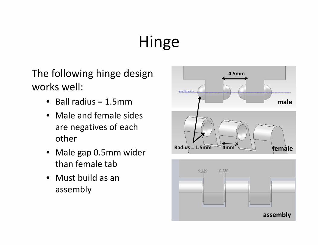
Hinge
The following hinge design works well:
• Ball radius = 1.5mm• Male and female sides are negatives of each other
• Male gap 0.5mm wider than female tab
• Must build as an assembly
4mm
4.5mm
male
female
assembly
Radius = 1.5mm

Example: Planetary Gear Set
This example includes the use of:• External Gears• Internal Gears• Captive Shafts• External Retaining Rings• Internal Retaining Rings

Planetary Gear Set Components
Orbit
Sun
Carrier & Planets
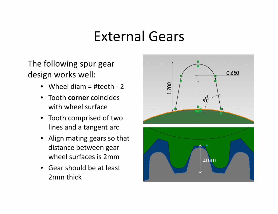
External Gears
The following spur gear design works well:
• Wheel diam = #teeth ‐ 2• Tooth corner coincides
with wheel surface• Tooth comprised of two
lines and a tangent arc• Align mating gears so that
distance between gear wheel surfaces is 2mm
• Gear should be at least 2mm thick
2mm

Internal Gears
The following spur gear design works well:
• Wheel diam = #teeth + 2• Tooth center coincides
with wheel surface• Tooth comprised of two
lines and a tangent arc• Align mating gears so that
distance between gear wheel surfaces is 2mm
• Gear should be at least 2mm thick 2mm

Captive Shafts ‐Male
Designing captive shafts:• Draw a shaft with the required dimensions
• Define the axis of the shaft
• Sketch the shape shown (figure above) in the middle of the shaft
• Revolve the sketch around the shaft axis
2.5mm
1mmShaft axes
Carrier
Captive shaft

Captive Shafts ‐ FemaleTo make the female component:• Define the rotation axis• Sketch the shape shown
(bottom figure) in the middle of the part
• The radius of the half circle must be equal to that of the male part
• Include 0.25mm clearance on each side of the shaft
• Revolve cut the sketch around the rotation axis
1mm
1.5mm
3mm
Gear axes
Gear cross section

Captive Shafts• Make as an assembly• Check for interference
(SolidWorks feature) before saving as STL
• Carefully free up components after printing
Carrier & planets assembly

External Retaining Rings
To create a slot for an external retaining ring:• 3 important dimensions to
look for:– ID = Inner Diameter– OD = Outer Diameter– T = Thickness
• Sketch the shaft:– ID’ <= ID – 0.2mm– T’ >= T + 0.2mm
• Create a revolved cut
OD
ID
ID’OD’
T’
Sun
Image source: arconring.com

ID
OD
Internal Retaining Rings
To create a slot for an internal retaining ring:• 3 important dimensions to
look for:– ID = Inner Diameter– OD = Outer Diameter– T = Thickness
• Sketch the slot:– OD’ >= OD + 0.2mm– T’ >= T + 0.2mm
• Create a revolved cut
ID’
OD’T’
cross section
Orbit: cross section
OrbitImage source: use‐enco.com