Embed Size (px)
Citation preview
STK – Missile Defense Introduction: STK provides missile defense professionals with an environment for performing system-level analysis of
threats, sensors, communications, intercept engagements, and defense architecture performance. This
scenario illustrates how STK can be used to model end-to-end missile defense simulation by highlighting
some of the core analysis features within the STK software for the missile defense community:
Modeling and simulating threat & interceptor missiles trajectories
Evaluating sensor platforms (satellites, aircraft, ships, etc.)
Evaluating radars placement, constraints, and performance
Evaluating communication links between assets
Situational Awareness
Pre & Post Mission Planning
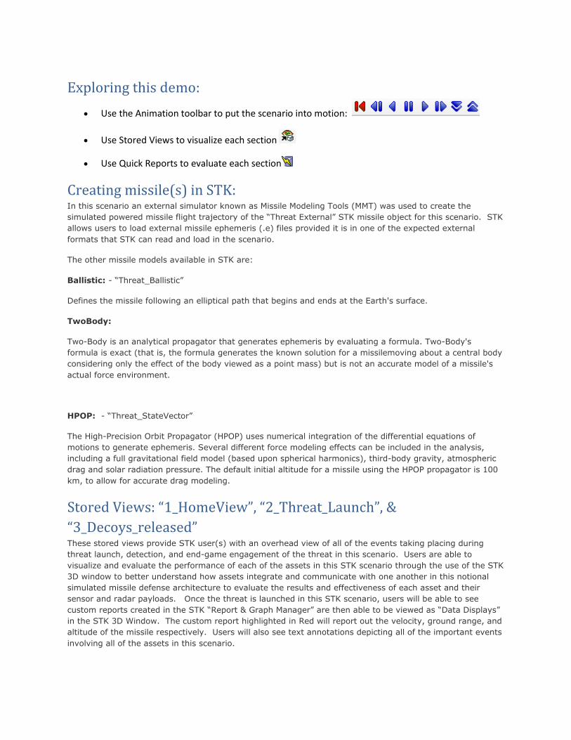
Scenario Storyline: The scenario begins with a new foreign threat launched from Masudan Ri, North Korea. The threat is a three
stage missile capable of impacting anyone of the major metropolitan cities on the west coast of the United
States and or Hawaiian Islands.
Exploring this demo:
Use the Animation toolbar to put the scenario into motion:
Use Stored Views to visualize each section
Use Quick Reports to evaluate each section
Creating missile(s) in STK: In this scenario an external simulator known as Missile Modeling Tools (MMT) was used to create the
simulated powered missile flight trajectory of the “Threat External” STK missile object for this scenario. STK
allows users to load external missile ephemeris (.e) files provided it is in one of the expected external
formats that STK can read and load in the scenario.
The other missile models available in STK are:
Ballistic: - “Threat_Ballistic”
Defines the missile following an elliptical path that begins and ends at the Earth's surface.
TwoBody:
Two-Body is an analytical propagator that generates ephemeris by evaluating a formula. Two-Body's
formula is exact (that is, the formula generates the known solution for a missilemoving about a central body
considering only the effect of the body viewed as a point mass) but is not an accurate model of a missile's
actual force environment.
HPOP: - “Threat_StateVector”
The High-Precision Orbit Propagator (HPOP) uses numerical integration of the differential equations of
motions to generate ephemeris. Several different force modeling effects can be included in the analysis,
including a full gravitational field model (based upon spherical harmonics), third-body gravity, atmospheric
drag and solar radiation pressure. The default initial altitude for a missile using the HPOP propagator is 100
km, to allow for accurate drag modeling.
Stored Views: “1_HomeView”, “2_Threat_Launch”, &
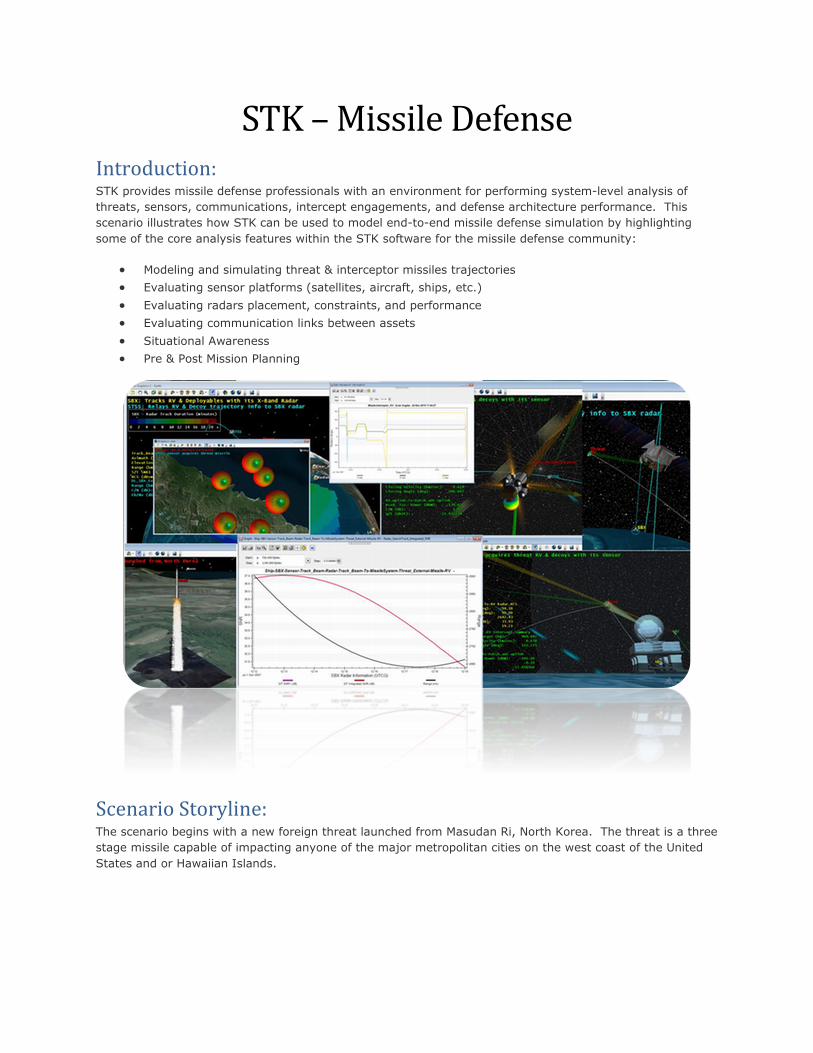
“3_Decoys_released” These stored views provide STK user(s) with an overhead view of all of the events taking placing during
threat launch, detection, and end-game engagement of the threat in this scenario. Users are able to
visualize and evaluate the performance of each of the assets in this STK scenario through the use of the STK
3D window to better understand how assets integrate and communicate with one another in this notional
simulated missile defense architecture to evaluate the results and effectiveness of each asset and their
sensor and radar payloads. Once the threat is launched in this STK scenario, users will be able to see
custom reports created in the STK “Report & Graph Manager” are then able to be viewed as “Data Displays”
in the STK 3D Window. The custom report highlighted in Red will report out the velocity, ground range, and
altitude of the missile respectively. Users will also see text annotations depicting all of the important events
involving all of the assets in this scenario.
Stored View: 1_Home_View:
Stored View: 2_Threat_Launch:
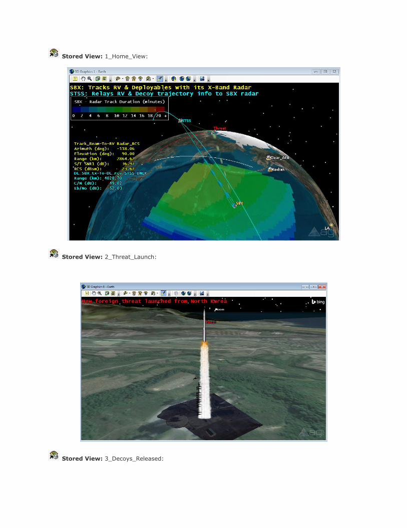
Stored View: 3_Decoys_Released:
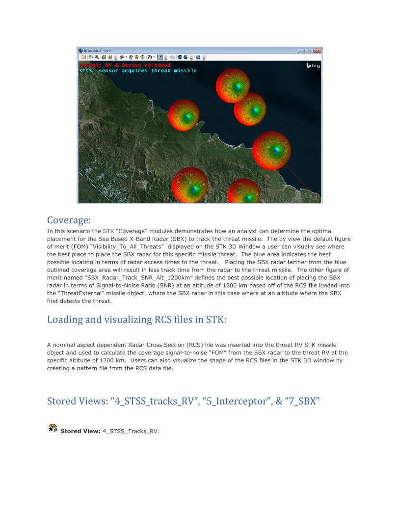
Coverage: In this scenario the STK “Coverage” modules demonstrates how an analyst can determine the optimal
placement for the Sea Based X-Band Radar (SBX) to track the threat missile. The by view the default figure
of merit (FOM) “Visibility_To_All_Threats” displayed on the STK 3D Window a user can visually see where
the best place to place the SBX radar for this specific missile threat. The blue area indicates the best
possible locating in terms of radar access times to the threat. Placing the SBX radar farther from the blue
outlined coverage area will result in less track time from the radar to the threat missile. The other figure of
merit named “SBX_Radar_Track_SNR_Alt_1200km” defines the best possible location of placing the SBX
radar in terms of Signal-to-Noise Ratio (SNR) at an altitude of 1200 km based off of the RCS file loaded into
the “ThreatExternal” missile object, where the SBX radar in this case where at an altitude where the SBX
first detects the threat.
Loading and visualizing RCS files in STK:
A nominal aspect dependent Radar Cross Section (RCS) file was inserted into the threat RV STK missile
object and used to calculate the coverage signal-to-noise “FOM” from the SBX radar to the threat RV at the
specific altitude of 1200 km. Users can also visualize the shape of the RCS files in the STK 3D window by
creating a pattern file from the RCS data file.
Stored Views: “4_STSS_tracks_RV”, “5_Interceptor”, & “7_SBX”
Stored View: 4_STSS_Tracks_RV:
Stored View: 4a_SBX:
Stored View: 5_Interceptor:
Stored View: 6_Kill_Vehicle:
Communications & Sensors Modeling:
Various targeted and fix sensors are modeled in the scenario to define communication links between assets
and track the threat missile in this scenario; starting with the targeted “Track_Sensor” sensor object
inserted on the STSS satellite. The sensor has a nominal range and grazing altitude constraint suitable for
this long-range exo-atmospheric missile flight. The sensor begins tracking the threat missile shortly before
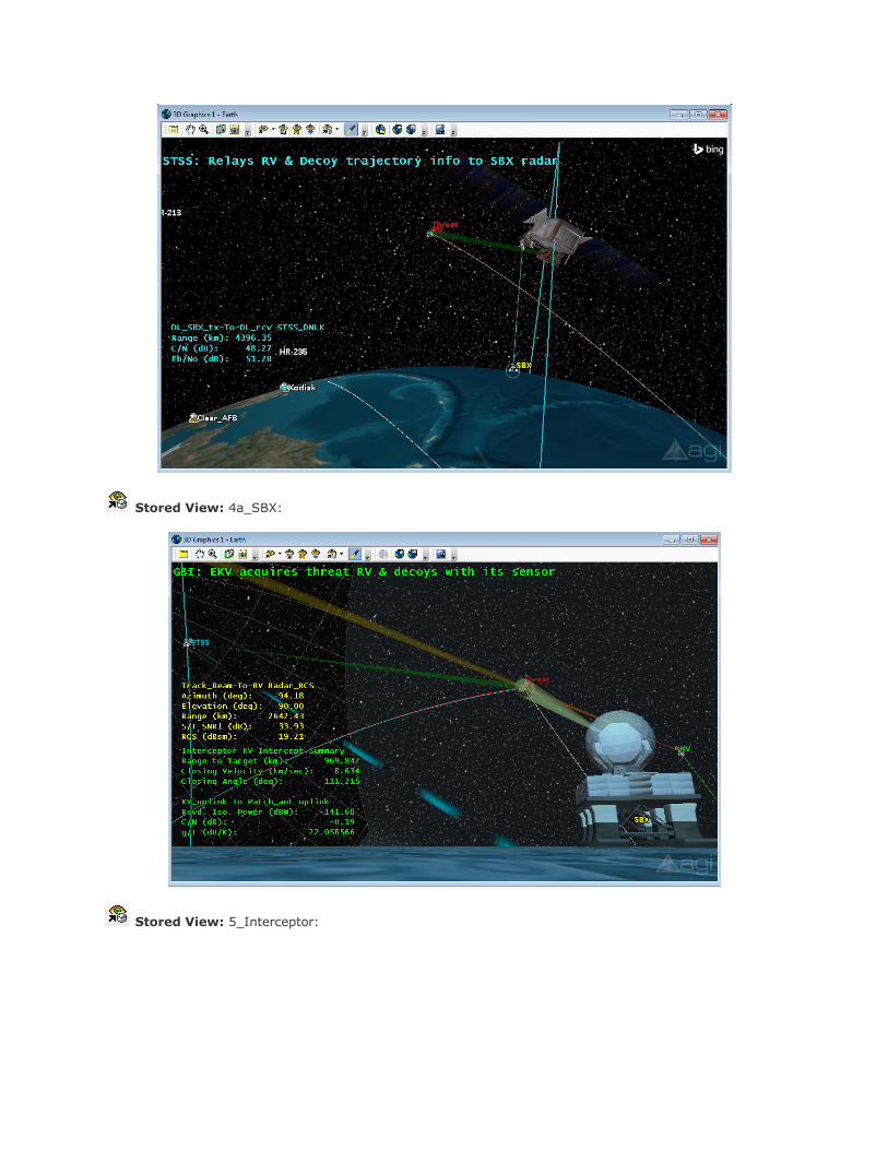
the Re-entry Vehicle (RV) and decoys are released. Once the STSS satellite acquires the threat missile with
its tracking sensor, it is able to simulate a comm downlink with the SBX radar with its targeted Gaussian
antenna transmitter. The Gaussian antenna pattern can be seen by zooming in on the STSS satellite object
in the STK 3D window where you will also see a custom comm data display report on the left hand side of
the 3D window. The STSS will also simulate a comm downlink to the Clear_AFB facility receiver to relay the
threat missile trajectory prior to the Ground Base interceptor being launched near Kodiak, Ak. The
“Clear_AFB” facility will also provide additional tracking of the threat missile with its defined complex sensor
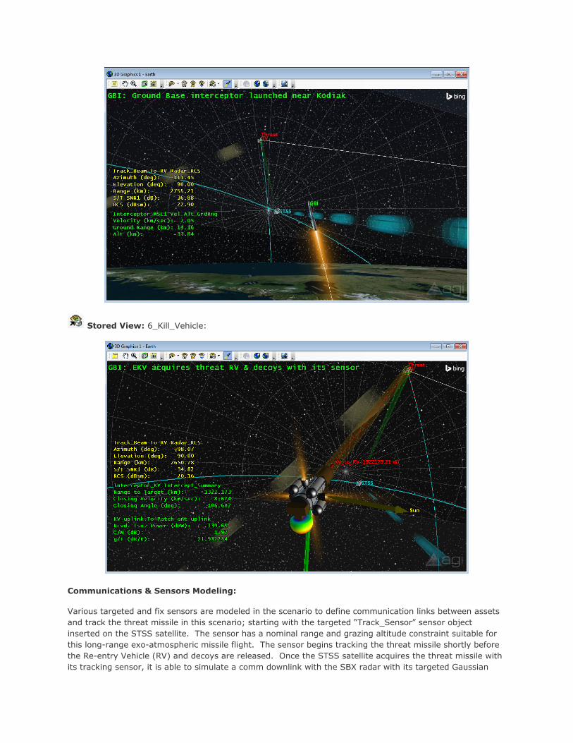
with a range of 4500 km. The sensor on the Kill Vehile (KV) ejected from the Ground Base Interceptor
(GBI) missile simulates an infrared seeker which detects and track all incoming objects. Initially when the
KV is deployed it uses it sensor to track the following stars (HR-213, HR-219, & HR-235) to orient itself
before the intercept with the RV can take place. The maneuvers are done through the use of the Multi-
Segment feature provided in the STK Attitude module. The KV is able to simulate the uplink of telemetry
data from the Kodiak facility by using a “Patch” external antenna pattern generated in Pattern Magus. This
software allows the ability for users to create their own custom external antenna files which can then be
integrated for comm analysis between assets in STK.
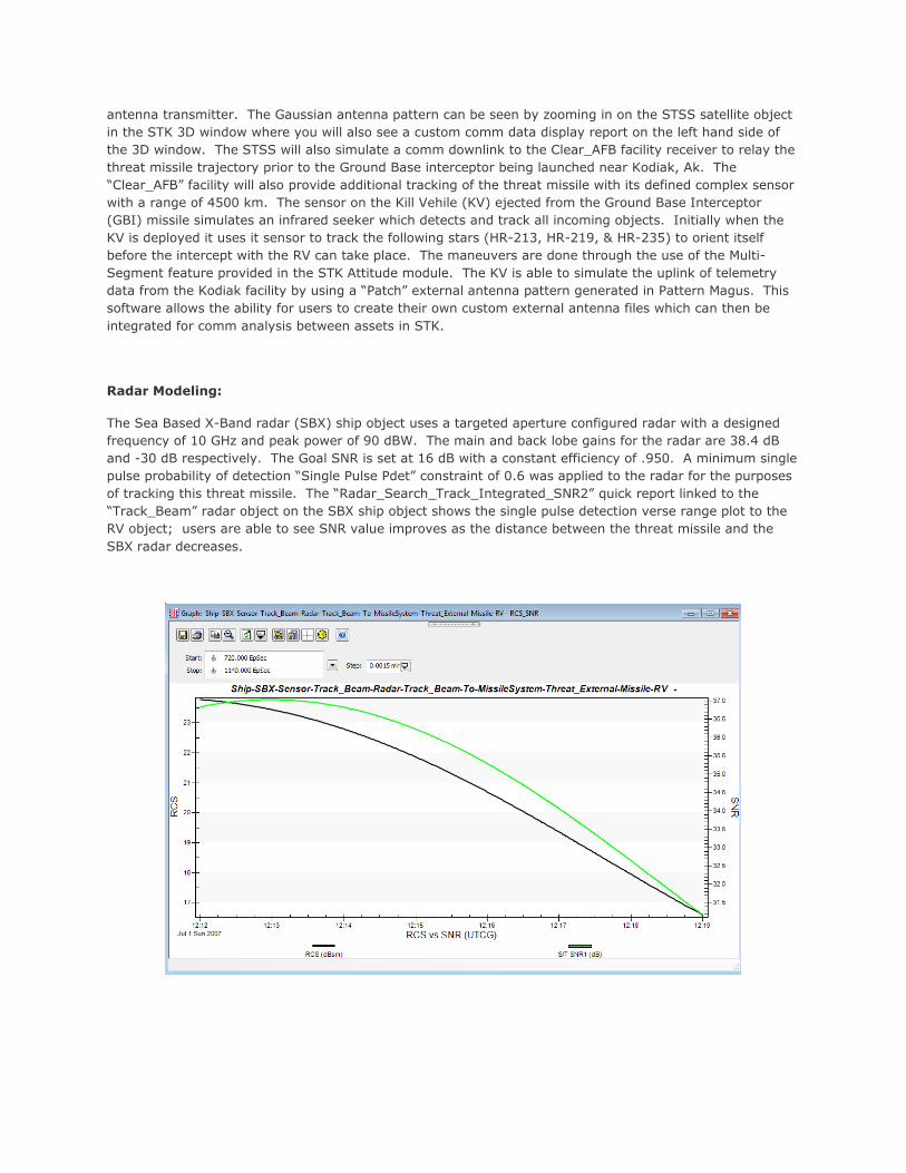
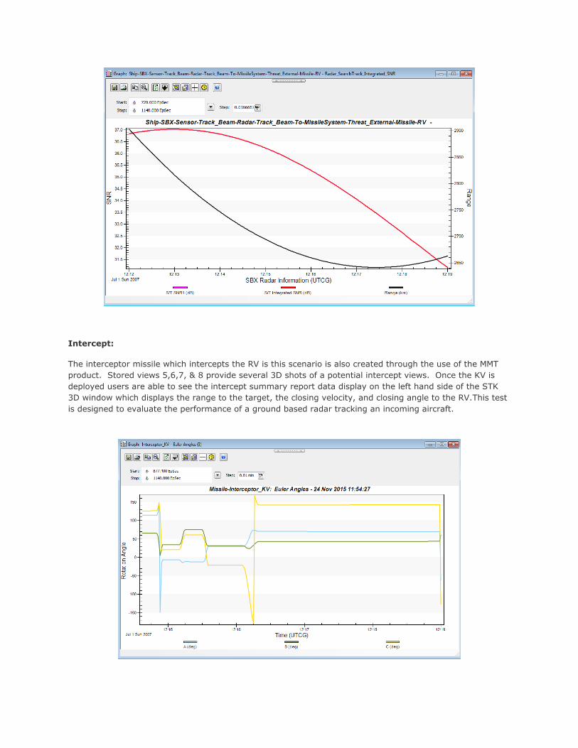
Radar Modeling:
The Sea Based X-Band radar (SBX) ship object uses a targeted aperture configured radar with a designed
frequency of 10 GHz and peak power of 90 dBW. The main and back lobe gains for the radar are 38.4 dB
and -30 dB respectively. The Goal SNR is set at 16 dB with a constant efficiency of .950. A minimum single
pulse probability of detection “Single Pulse Pdet” constraint of 0.6 was applied to the radar for the purposes
of tracking this threat missile. The “Radar_Search_Track_Integrated_SNR2” quick report linked to the
“Track_Beam” radar object on the SBX ship object shows the single pulse detection verse range plot to the
RV object; users are able to see SNR value improves as the distance between the threat missile and the
SBX radar decreases.
Intercept:
The interceptor missile which intercepts the RV is this scenario is also created through the use of the MMT
product. Stored views 5,6,7, & 8 provide several 3D shots of a potential intercept views. Once the KV is
deployed users are able to see the intercept summary report data display on the left hand side of the STK
3D window which displays the range to the target, the closing velocity, and closing angle to the RV.This test
is designed to evaluate the performance of a ground based radar tracking an incoming aircraft.