Embed Size (px)
Citation preview

Stilo
LED Lights and Aquarium Controller
• Up to five separate PWM signals for independent control of LEDs colors;
• moonlight channel with simple and real time modes;
• dusk and down effect for LEDs and moonlight;
• real time clock;
• water and LEDs heatsink temperature sensors;
• speed control for heatsink fans;
• all settings are stored in EEPROM;
• simple ATO (water top up system) controlled by 1 float switch.
Stilo 3.0 www.code.google.com/p/stilo

Changes:
ver. 3.0• Updated the sketch and libraries to be compatible with Arduino IDE 1.0;
• Increased LED channels number to 5;
• The number of LED channels displayed and controlled can be changed in settings;
• Added moonlight channel;
• Added ATO with one floating switch;
• Rewrote the code to remove buggy String objects;
• Changed the way temp sensors are addressed;
• Added screen brightness adjustment;
• Added LEDs color mixer screen;
• The display automatically gets back to main screen after 10 min of user inactivity.
v.2.5• Updated to latest ITDB02_Graph16 library that support more screen types;
• LEDs output is set in percent (not 0-255 values);
• Some general visual changes;
• Added configuration of LED fans temperatures;
• Safety feature - dimming LEDs if heatsink is too hot;
• Can restore settings on start or by option in menu;
• Temperature alarm can be acknowledged to turn off buzzer;
• Removed control of heater and cooler;
• Added 25kHz signal to control LEDs heatsink fans speed.
v. 2.1• Water temperature sensor changed to digital DS18B20;
• Pins to control water heater, cooler and for alarm buzzer;
• Led heatsink temperature sensor (DS18B20);
• Speed control for heatsink fans;
• Led values can be changed from menu;
• Setting can be stored in EEPROM.
v. 1.5 • Minor changes to design;
• Added temperature probe and temperature control page;
• Tidied up the code.
v.1 Initial release
Stilo 3.0 www.code.google.com/p/stilo

Schematic:
Stilo 3.0 www.code.google.com/p/stilo
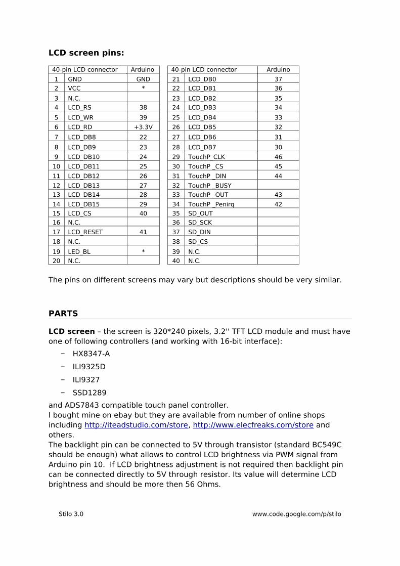
LCD screen pins:
40-pin LCD connector Arduino 40-pin LCD connector Arduino
1 GND GND 21 LCD_DB0 37
2 VCC * 22 LCD_DB1 36
3 N.C. 23 LCD_DB2 35
4 LCD_RS 38 24 LCD_DB3 34
5 LCD_WR 39 25 LCD_DB4 33
6 LCD_RD +3.3V 26 LCD_DB5 32
7 LCD_DB8 22 27 LCD_DB6 31
8 LCD_DB9 23 28 LCD_DB7 30
9 LCD_DB10 24 29 TouchP_CLK 46
10 LCD_DB11 25 30 TouchP _CS 45
11 LCD_DB12 26 31 TouchP _DIN 44
12 LCD_DB13 27 32 TouchP _BUSY
13 LCD_DB14 28 33 TouchP _OUT 43
14 LCD_DB15 29 34 TouchP _Penirq 42
15 LCD_CS 40 35 SD_OUT
16 N.C. 36 SD_SCK
17 LCD_RESET 41 37 SD_DIN
18 N.C. 38 SD_CS
19 LED_BL * 39 N.C.
20 N.C. 40 N.C.
The pins on different screens may vary but descriptions should be very similar.
PARTS
LCD screen – the screen is 320*240 pixels, 3.2'' TFT LCD module and must have one of following controllers (and working with 16-bit interface):
− HX8347-A
− ILI9325D
− ILI9327
− SSD1289
and ADS7843 compatible touch panel controller.I bought mine on ebay but they are available from number of online shops including http://iteadstudio.com/store, http://www.elecfreaks.com/store and others.The backlight pin can be connected to 5V through transistor (standard BC549C should be enough) what allows to control LCD brightness via PWM signal from Arduino pin 10. If LCD brightness adjustment is not required then backlight pin can be connected directly to 5V through resistor. Its value will determine LCD brightness and should be more then 56 Ohms.
Stilo 3.0 www.code.google.com/p/stilo

Arduino Mega – either older version with ATmega1280 microcontroller or newer Mega 2560.
Proto shield for Arduino Mega to put all components together. I have made one myself from generic proto board but dedicated proto boards are available from many shops.Also available are special shields for the LCD screens. They have all components and connectors that allow for the screen to be easily connected to Arduino. Very often they comes with RTC clock build in but they are not suitable for soldering more components so a proto board is still needed. All boards are then stacked on top of each other.I have decided not to use LCD shield and put all components on one proto board.
What you can't see on the picture is Arduino itself which is connected underneath my proto board.
RTC (real time clock), already assembled or it can be made from parts:
• DS1307 chip
• 32.768kHz Crystal
• CR2032 battery and holder
• 2 x 10kOhm resistors
• 0.1uF capacitor
Below is schematic if you build it from parts:
Stilo 3.0 www.code.google.com/p/stilo
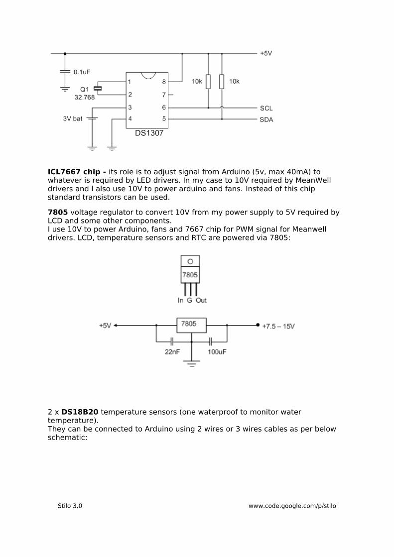
ICL7667 chip - its role is to adjust signal from Arduino (5v, max 40mA) to whatever is required by LED drivers. In my case to 10V required by MeanWell drivers and I also use 10V to power arduino and fans. Instead of this chip standard transistors can be used.
7805 voltage regulator to convert 10V from my power supply to 5V required by LCD and some other components.I use 10V to power Arduino, fans and 7667 chip for PWM signal for Meanwell drivers. LCD, temperature sensors and RTC are powered via 7805:
2 x DS18B20 temperature sensors (one waterproof to monitor water temperature).They can be connected to Arduino using 2 wires or 3 wires cables as per below schematic:
Stilo 3.0 www.code.google.com/p/stilo
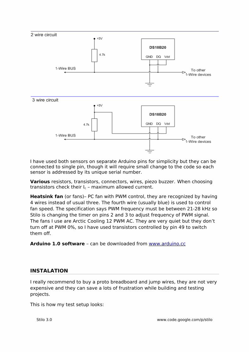
I have used both sensors on separate Arduino pins for simplicity but they can be connected to single pin, though it will require small change to the code so each sensor is addressed by its unique serial number.
Various resistors, transistors, connectors, wires, piezo buzzer. When choosing transistors check their Ic – maximum allowed current.
Heatsink fan (or fans)– PC fan with PWM control, they are recognized by having 4 wires instead of usual three. The fourth wire (usually blue) is used to control fan speed. The specification says PWM frequency must be between 21-28 kHz so Stilo is changing the timer on pins 2 and 3 to adjust frequency of PWM signal. The fans I use are Arctic Cooling 12 PWM AC. They are very quiet but they don’t turn off at PWM 0%, so I have used transistors controlled by pin 49 to switch them off.
Arduino 1.0 software – can be downloaded from www.arduino.cc
INSTALATION
I really recommend to buy a proto breadboard and jump wires, they are not very expensive and they can save a lots of frustration while building and testing projects.
This is how my test setup looks:
Stilo 3.0 www.code.google.com/p/stilo

If you are new to Arduino then first make sure it's all working: install Arduino software and necessary drivers, connect USB cable to Arduino board and upload one of simple examples like 'Blink' to ensure everything is working fine. Then play with more example sketches to get familiar with Arduino environment.
To start with Stilo – first copy libraries from zip to appropriate folder – see http://arduino.cc/en/Guide/Libraries for details.
Next thing is to make screen running - connect it to Mega board (i.e. using breadboard). The screen has 40-pin connector so I used ATA cable (40-wire, old type). Data pins are connected through 12k resistors. LCD brightness pin can be connected to +5V through resistor (the brightness can be adjusted by changing the resistor value, I have used 82 Ohms) or with transistor that allows to control brightness by pin 10.Check if the screen is working by uploading example: File > Examples > UTFT > Arduino > UTFT_Demo_320x240. The touch screen - upload touch example File > Examples > UTouch > Arduino > UTouch_ButtonTest and check if it's working. Touch screen needs to be calibrated, this is done by running calibration sketch located in examples and then following on screen instructions.
At this point we can connect RTC to the Arduino and upload Stilo sketch and check if it displays time and date.
Stilo 3.0 www.code.google.com/p/stilo
The last thing is adding the rest of components – temperature sensors, resistors, transistors and test all Stilo functions.
LEDS and drivers
The controller can be used with any LED driver that is PWM dimmable (and will accept 480Hz signal from Arduino). The most popular are Meanwell and Buckpucks but there are plenty of others.
LEDs and drivers – I'm not going into much details here as there are many combinations of LEDs and drivers types. There is plenty of information on the net, specifically check DIY and lightning sections on all popular marine forums.
Choice of LEDs – another topic I'm not able to cover here. I have started with (recommended at the time) 50/50 XPE royal blues and HR-E cold whites but soon discovered (as other people using the same setup) that this combo gives too washed out effect. Since then I changed some of cold whites for neutral whites but still I'm not 100% happy with the effect.
There are couple of good threads on marine forums about this topic (search for 'leds aesthetics'). Right now I'm thinking about changing some of royal blues for cold blues, adding few violet leds and maybe couple of reds for good measure.
Pins settings
Those settings specifies pins on board used for specific parts, change them if needed:
UTFT myGLCD(SSD1289,38,39,40,41);
Change the screen type and pins as needed.
Refer to pdf in UTFT library folder.
UTouch myTouch(46,45,44,43,42);
Pins for touch controller.
#define ONE_WIRE_BUS_W 47#define ONE_WIRE_BUS_H 48
Pins for temperature sensors.
const byte ledPinCh1 = 6;const byte ledPinCh2 = 7;const byte ledPinCh3 = 8; const byte ledPinCh4 = 11; const byte ledPinCh5 = 12;
Pins for LEDs PWM signals.
const byte moonlightPin = 13; Pin for moonlight PWM signal.
const byte LCDbrightPin = 10; Pin to control screen brightness.
Stilo 3.0 www.code.google.com/p/stilo

const int AlarmBuzzPin = 4; Pin for piezo buzzer.
const int fan1PWMpin = 2;const int fan2PWMpin = 3;
Pins for fans PWM signals (25kHz)
const int fan1TranzPin = 49; Pin for transistor that turns on/off fans
const byte ATOswitchPin = 19; Pin for water level float switch for ATO.
const byte ATOpumPin = A1; Pin to control water pump for ATO.
Sketch settingsSome of the settings below are permanent, they can't be changed after sketch is uploaded.
const byte numberOfCh = 5; Permanent setting, changes the number of LED channels (colors) that are controlled by Stilo.
const char *namesCh[] = {" ", "RB", "WH", "UV", "TK", "DR"};
Permanent setting, short name for each channel (RB – royal blue, WH – white and so on). First value in the array is not used.
const byte rgbCh1[] = {30, 30, 255}; const byte rgbCh2[] = {255, 255, 255};const byte rgbCh3[] = {176, 28, 203};const byte rgbCh4[] = {0, 255, 228};const byte rgbCh5[] = {255, 0, 0};
Permanent setting, RGB color values for each channel that is used to display bars.
boolean BUCKPUCK = false; Permanent setting, true if backpuck style drivers are used.
const boolean readEEonStart = 0; Permanent setting, if true the settings saved in EEPROM are loaded on start, if false settings can be loaded by option in menu.
const int fanHyster = 300; Permanent setting, temperature difference between fans turning on and off *1.
const float setTempC = 27.0; Desired temperature for water temp. alarm.
Stilo 3.0 www.code.google.com/p/stilo
const float AlarmOffTemp = 0.0; Difference from setTempC when alarm in on (if '0' alarm is off).
const int HsinkTempMin = 30; Temperature when fans starts (also see 'fanHyster').
const int ccc = 40; Temperature when fans speed is 100%.
const int HsinkTempCutOff = 70; Temperature when controller starts to dim LEDs, for each °C above this value light is dimmed 10% (if '0' this mechanism is turned off)
int ATOmax = 5; Max time in seconds for ATO pump, it's disabled if it's running for longer.
const boolean moonTimesReal = 1; False for simple moonlight mode, true for real time mode.
const int setMoonrise = 18; const int setMoonset = 9;
Moonrise and moonset times for simple mode.
const byte setNewMoonLight = 10; const byte setFullMoonLight = 80;
Moonlight min and max light values.
const int latitude = 52; const int longtitude = 0;
Latitude and longitude for real time mode, negative if south or west.
byte LCDbright = 70; LCD brightness.
1) In the code used to control 25kHz PWM, value 639 represents fans speed of 100% so 300 is almost 50%. This means that fans will turn on when LEDs temperature is about half way between HsinkTempMin and HsinkTempMax. In example here it's 30 and 40 °C so the fans will start at 35 °C with 50% speed and stop at 30 °C. I found the fans to be very effective and without this mechanism they kept to turn on and off every few seconds.
LEDs output settings:
// Channel 1 leds output values %:byte ch1led[96] = { 0, 0, 0, 0, 0, 0, 0, 0, //0 1 0, 0, 0, 0, 0, 0, 0, 0, //2 3 0, 0, 0, 0, 0, 0, 0, 0, //4 5 0, 0, 0, 0, 0, 0, 11, 11, //6 7 11, 11, 11, 12, 12, 13, 13, 14, //8 9 16, 16, 16, 16, 20, 25, 30, 35, //10 11 40, 47, 47, 47, 47, 47, 47, 47, //12 13 47, 47, 47, 47, 47, 47, 47, 47, //14 15 47, 47, 47, 47, 47, 47, 47, 47, //16 17
Stilo 3.0 www.code.google.com/p/stilo
47, 47, 47, 47, 47, 40, 35, 30, //18 19 25, 20, 15, 11, 11, 11, 11, 11, //20 21 0, 0, 0, 0, 0, 0, 0, 0 //22 23};
Those arrays keep LEDs output values for each channel respectively. Each value is the light output in 15 min intervals. Each line represent 2 hours. So the line:
25, 20, 15, 11, 11, 11, 11, 11, //20 21
gives us 25% output at 20:00, 20% at 20:15, 15% at 20:30 and so on.The light output is adjusted in 1 min intervals and those values are calculated in real time based on previous and next value. Those tables are loaded on start, however they can be overridden if the light outputs have been previously changed and saved into EEPROM and the option readEEonStart is on.
OPERATION
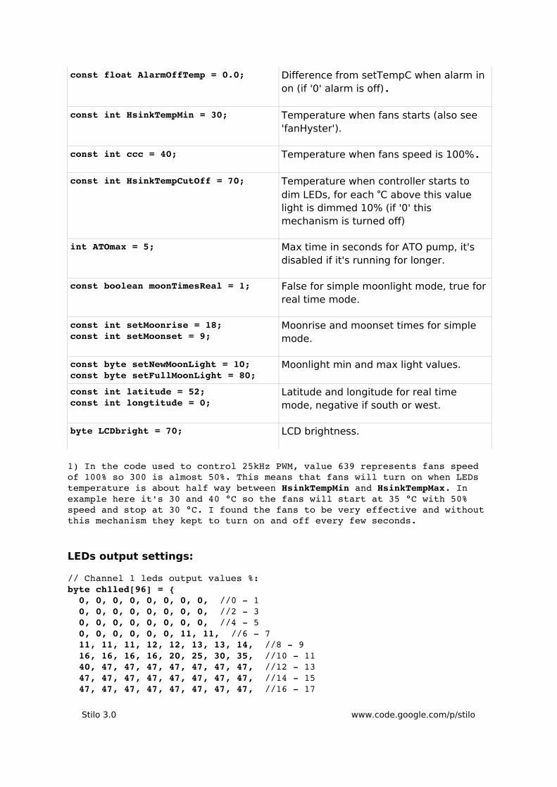
Main screen Main screen displays time and date, LEDs output values, water and heatsink temperatures, fans speed and moonlight information. The number of bars displayed depends on number of LEDs channels configured. In the same way LEDs menu, test screen and color mixer screens depends on configured number of channels.Moonlight information includes moon's picture in current phase, moon illumination and current phase. Moonrise and moonset time is displayed only in real time mode.
Stilo 3.0 www.code.google.com/p/stilo
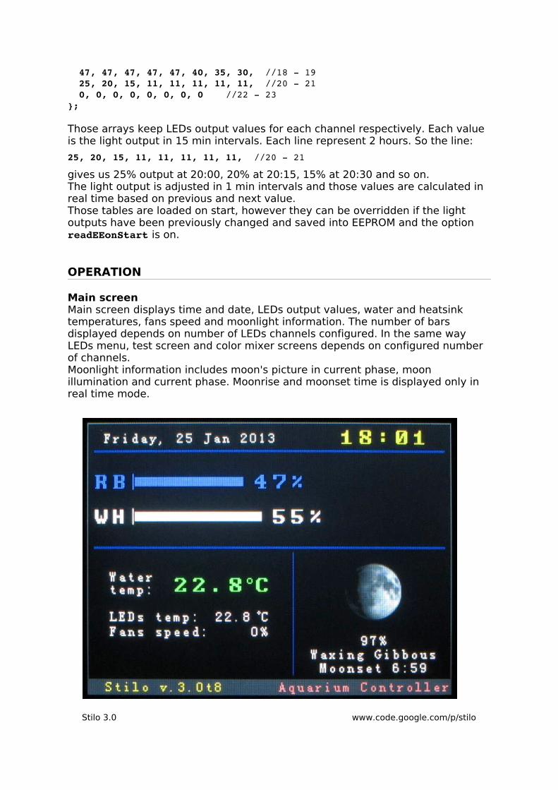
Menu:
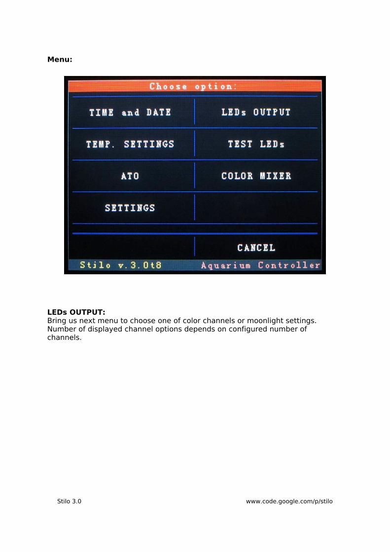
LEDs OUTPUT:Bring us next menu to choose one of color channels or moonlight settings. Number of displayed channel options depends on configured number of channels.
Stilo 3.0 www.code.google.com/p/stilo
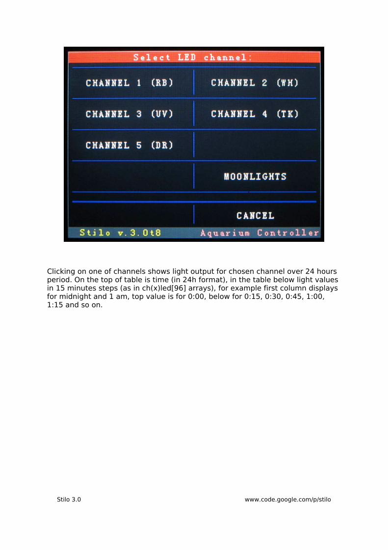
Clicking on one of channels shows light output for chosen channel over 24 hours period. On the top of table is time (in 24h format), in the table below light values in 15 minutes steps (as in ch(x)led[96] arrays), for example first column displays for midnight and 1 am, top value is for 0:00, below for 0:15, 0:30, 0:45, 1:00, 1:15 and so on.
Stilo 3.0 www.code.google.com/p/stilo

The values can be changed by choosing 'Change'.This bring us the screen that allows to change light output for chosen channel. On the top of the screen we have a time, clicking on one square will display bars for chosen time. In the example below chosen is 10 am and 11 am. The left bar display light output for 10:00 am, next one for 10:15 and so on.
Stilo 3.0 www.code.google.com/p/stilo

The light values can be changed by clicking on the bar or up/down arrows.'Save' applies the changes and saves the values to EEPROM memory.
Moonlight: Moonlight can work in two modes: simple and real time.In simple mode (switch on the top of the screen in OFF position) the moonrise and moonset times are configured by user in 'Set times if above is OFF' section. Simply moonlight will be turned on on chosen moonrise time (17:00 on the screen shot) on turned off on moonset (9:00 am).If the switch is in ON position moonrise and moonset times are greyed out and real times mode in on. In this mode moonrise and moonset times are calculated according to local time and configured latitude and longitude. The next event is displayed on main screen so if the moon is up the screen will display next moonset time and if moon is down it will display moonrise time.The bottom section applies to both modes and it allows to change moonlight minimum light output (for new moon) and maximum value for full moon. So during new moon the moonlight doesn't have to off and on full moon it doesn't have to be 100%. In between the light output is the percent of the value between min and max, for the example below if on particular day moon is illuminated in 75% the moon light value will be 75% between 19% and 70% of maximum LED output.
Stilo 3.0 www.code.google.com/p/stilo

TEST LEDs OUTPUT:
Stilo 3.0 www.code.google.com/p/stilo

Allows to test configured light output over time and LED colour blending.
Stilo 3.0 www.code.google.com/p/stilo

COLOR MIXER:
Allows to test LEDs color blending.
Stilo 3.0 www.code.google.com/p/stilo

TIME and DATE:
TEMP. SETTINGS:
Stilo 3.0 www.code.google.com/p/stilo
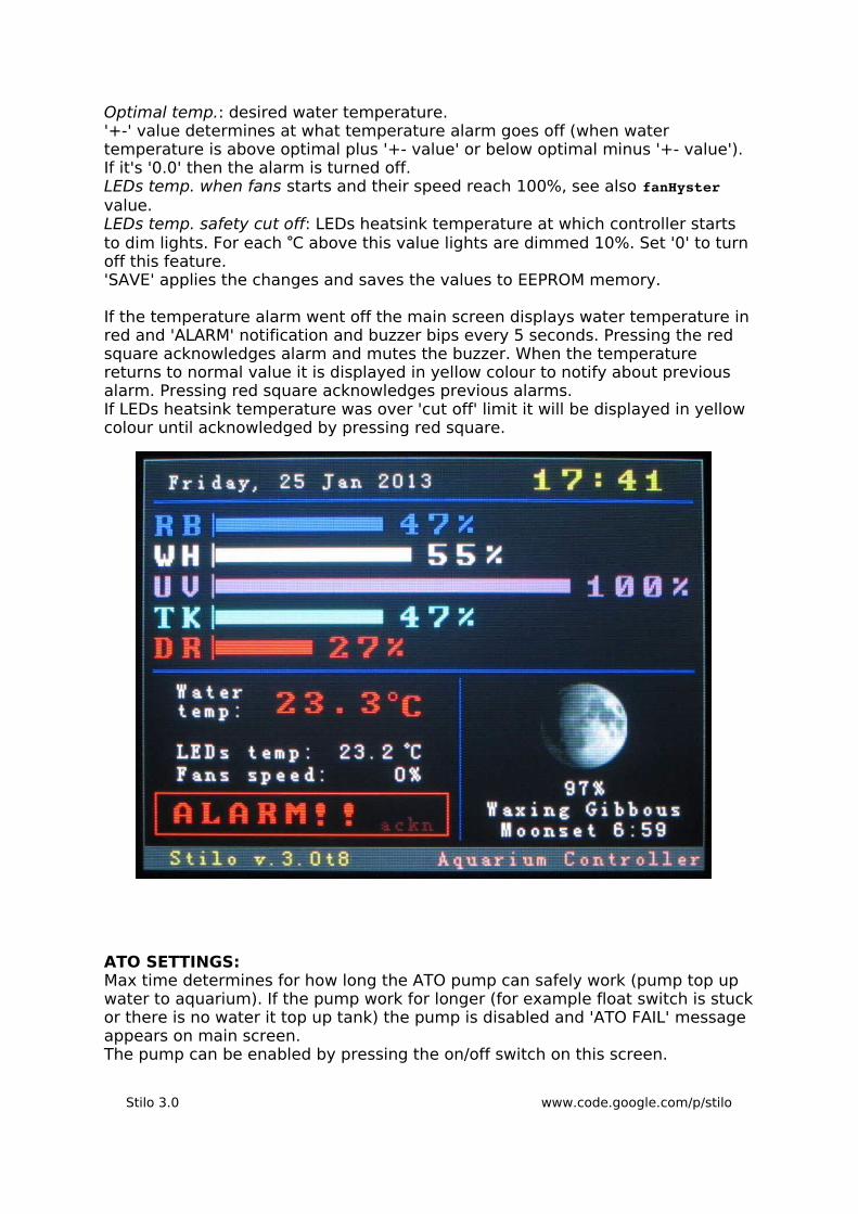
Optimal temp.: desired water temperature. '+-' value determines at what temperature alarm goes off (when water temperature is above optimal plus '+- value' or below optimal minus '+- value'). If it's '0.0' then the alarm is turned off.LEDs temp. when fans starts and their speed reach 100%, see also fanHyster value.LEDs temp. safety cut off: LEDs heatsink temperature at which controller starts to dim lights. For each °C above this value lights are dimmed 10%. Set '0' to turn off this feature.'SAVE' applies the changes and saves the values to EEPROM memory.
If the temperature alarm went off the main screen displays water temperature in red and 'ALARM' notification and buzzer bips every 5 seconds. Pressing the red square acknowledges alarm and mutes the buzzer. When the temperature returns to normal value it is displayed in yellow colour to notify about previous alarm. Pressing red square acknowledges previous alarms.If LEDs heatsink temperature was over 'cut off' limit it will be displayed in yellow colour until acknowledged by pressing red square.
ATO SETTINGS:Max time determines for how long the ATO pump can safely work (pump top up water to aquarium). If the pump work for longer (for example float switch is stuck or there is no water it top up tank) the pump is disabled and 'ATO FAIL' message appears on main screen.The pump can be enabled by pressing the on/off switch on this screen.
Stilo 3.0 www.code.google.com/p/stilo

GENERAL SETTINGS:Screen brightness is self-explanatory.'SAVE' will save all current settings to EEPROM memory.'LOAD' will load all settings from EEPROM.
Stilo 3.0 www.code.google.com/p/stilo

LINKS:
Stilo:
www.code.gogle.com/p/stilo
http://arduino.cc/forum/index.php/topic,54196.0.html
http://www.thesaltybox.com/forum/tank-mods-diy/127554-led-lights-controller-tft-lcd-touch-screen.html
LEDs color choice (very long threads, it may be cut to posts from last year or so):
http://www.nano-reef.com/topic/246394-led-aesthetics-what-do-you-really-think-of-your-color/
http://www.reefcentral.com/forums/showthread.php?t=1885076
LEDs and drivers (those links are a good point to start):
http://www.nano-reef.com/topic/206246-48-led-fixture-lots-of-photos/
http://www.nano-reef.com/topic/202425-xcube-26-led-upgrade-repost/?pid=2329379#entry2329379
http://www.ultimatereef.net/forums/showthread.php?t=363432
Good place to source LEDs in specific bins:
http://www.cutter.com.au/
Stilo 3.0 www.code.google.com/p/stilo


![[HOW-To] Instalando Entrada Auxiliar No Som Do Stilo Versão MID - Artigos & How to - Clube Stilo Brasil](https://img.pdfslide.us/doc/110x75/55cf967d550346d0338bce37/how-to-instalando-entrada-auxiliar-no-som-do-stilo-versao-mid-artigos.jpg)