Embed Size (px)
Citation preview

StickyMatTM
Matting System Installation Manual
Technical helpline:US:1-888-927-6333
Canada:1-888-592-7687
IMPORTANTRead this manual before attempting to install your Warmup heating system.Incorrect installation could damage the heating system and will invalidate the warranty.
v1.0 01/2015
™The world’s best-selling electric floor heating brand

2
Before you Begin
Thank you for purchasing the Warmup® StickyMat.
This manual contains IMPORTANT information regarding the safe use and installation of your heating mats. Please read through the entire manual carefully before you install or use the product.
ITEMS INCLUDED IN THE WARMUP® KIT:• StickyMat• Installation Manual
YOU MAY ALSO NEED:• 3iE thermostat with GFCI• Floor Sensor (included with 3iE)• Alligator Tester or Multimeter
Double check your measurements and ensure that you have the correct mat size for the area you wish to heat. The heating element MUST NOT be installed under appliances or permanent fixtures and fittings such as refrigerators, cabinets, tubs, vanity units etc. Below is a quick reference guide.
If you are missing any items from the box or believe that you have the incorrect heating mat to cover the area required, please call the helpline for further assistance.
Product InformationThe Warmup heating mat consists of a twin conductor resistance-heating element woven onto a fiberglass mat. The heating element is insulated with Fluoropolymer (FP) with high dielectric strength and high temperature properties. The conductors are covered by a metallic sheath providing additional mechanical strength and a ground path. A final outer jacket of Fluoropolymer is given to make it sturdier and provide corrosion protection.
The heating cable is terminated at one end with a 10’ cold lead. The conductor cores and ground braid are factory joined in a water resistant joint assembly to each supply conductor and ground conductor of the unheated lead. The heater is terminated at the other end with a smaller water resistant joint.
Inspect the entire heating cable for damage. This includes the factory made joint and end termination. If any parts are damaged contact the technical helpline.
The Warmup Heating Mat is approved.
Model Mat length (ft)
Width Area (Sqft)
Wattage Amps Resistance
NADWM-9-120 3.0 3.0 9 126 1.05 114.3
NADWM-15-120 5.0 3.0 15 210 1.75 68.5
NADWM-18-120 6.0 3.0 18 252 2.10 57.1
NADWM-24-120 8.0 3.0 24 336 2.80 42.9
NADWM-30-120 10.0 3.0 30 420 3.50 34.3
3
Do’s
DO carefully read this installation manual before commencing installation.
DO maintain a gap of min. 2”, max. 4” between the heating cable runs at all times.
DO make sure all electrical work is done by qualified persons in accordance with local building and electrical codes, the National Electrical Code (NEC), especially article 424, Part V of the NEC, ANSI/NFPA 70, for the US and Canadian Electrical Code, Part 1, for Canada.
DO check the resistance of the heating before, during, and after installation to ensure that the heating cable has not been damaged. The value should match the rating label found on the product. A tolerance of +/-5% is allowed.
DO ensure that the heating mat is connected to a Class A Ground Fault Circuit Interrupter (GFCI) when used in bathrooms. Check your local code requirements for installations outside of bathrooms. It is not common to require a GFCI protection outside of bathrooms.
DO plan the heating system layout and installation so that any drilling after tiling (e.g. for fixtures such as vanity units, tubs) will not damage the wiring. Remember to keep a copy for future reference.
DO take some pictures of the mat installation before installing the floor covering for future reference.
DO ensure that the minimum bending radius is no less than 1”(25mm) for the heating cable.
DO allow sufficient drying/curing of the subfloor before commencing installation of the heating mat.
DO ensure that each tile is solidly bedded in tile adhesive, with no gaps or voids beneath.
DO make sure that ALL heating cable including the joints are positioned under the tiles and completely embedded in adhesive.
DO remember to install the floor probe for the Warmup® thermostat. The floor sensor should be located in the centre of two heating element runs. Ensure that the sensor does not touch or cross over any of the heating cables.
DO ensure that the cold tail conduit is kept separate from the sensor conduit.
DO remember to attach the rating labels included within this manual to the circuit breaker and thermostatic controls.

4
... and Don‘ts
DON’T allow the heating cables on the mat to cross over or touch each other at any point as this can cause the cable to overheat.
DON’T cut or shorten the heating cable at any time.
DON’T secure the cable with the use of staples or other metal fixings.
DON’T store tiles, sharp or heavy objects on any of the wiring while tiling or bang a trowel on the installation area to remove excess mortar from the trowel.
DON’T install the heating mat below 5°F (-15°C) ambient temperature.
DON’T attempt to bypass the GFCI if it trips and cannot be reset during normal operation. Consult a qualified electrician or call the helpline for further assistance.
DON’T install the heating element under permanent fixtures.
DON’T commence installation on a mud job/screed that has not been fully cured.
DON’T use the heating system until you have allowed sufficient drying period for the finished floor. Check adhesive manufacturer’s instructions.
DON’T cover the cold lead joint or termination joint with tape when securing the subfloor. This may cause air pockets resulting in the joints overheating.
DON’T install the heating mat beyond the room or area in which they originate.
DON’T attempt to repair the heating cable if it becomes damaged. Call the technical helpline for further instructions.
DON’T allow the thermostat to exceed the maximum temperature for your final floor finish. Always check the maximum temperatures allowed with the floor covering manufacturer.
DON’T install the cold leads closer than 2” from the heating cable on the mat.
5
The StickyMat system is designed for installation under tile and stone. For use under other surfaces, please call Warmup at 1-888-927-6333.
Note: The UL Listing for this product covers use in wet locations for CANADA only. Wet location installation in United States shall be in accordance with the National Electric Code, NFPA 70 and any other applicable jurisdictional code and final acceptance is to be made by the Authority Having Jurisdiction (AHJ).
Thermal Insulation The insulation levels of a floor will affect both the performance & running costs of the under tile heating mat. Using the Heating Mat without thermal insulation can take up to 5 hours to heat a room whereas a system with thermal insulation takes less than an hour.
If the Warmup heating mat is being installed onto a concrete base it is highly recommended that a layer of insulation is used prior to installing the heating mat. The thermal insulation re-flects the heat upwards instead of allowing heat to penetrate into the subfloor, greatly improv-ing the warm-up times & running costs.
The Warmup insulation boards are fixed to the base using screws and tile adhesive. The thickness of insulation required will depend on whether it is for floor renovation or a new floor.
Heating Mat Selection

6
Ensure that the subfloor is smooth, dry and free from dust. Visually check that there are no objects on the floor that might damage the heating mat.
The basic rule is that if the floor is ready for tile, it is ready for Warmup. Consider floor prep with a qualified flooring installer. StickyMats can be installed on plywood, cement boards and cement slabs.
Always let leveling compounds cure before installing your StickyMat system.
Over concrete slabs, consider the use of Warmup insulation boards for best results. Review specific installation guidelines online or call Warmup at 1-888-927-6333.
Where necessary, an appropriate smoothing compound should be applied and allowed to cure.
If the cable is being fitted to a solid floor it is essential that the concrete slab has been allowed to cure.
If using the Warmup insulation boards, use a suitable cement based adhesive or screws to fix boards to the subfloor as per the instructions.
If installing in a wet room ensure a slope in the mortar bed is maintained in order to direct water to the drain pipe.
You are now ready to lay the heating mat.
Anti-fracture Membrane
Warmup heating mats are to be installed UNDER anti-fracture membranes. Follow the manufacturer’s guidelines and ensure the mats are covered with thin-set or self-leveling compound before applying the membrane. Do not apply floor heating systems above the membrane as air-pockets may develop in the thin set and cause the cable to overheat. Anti-fracture membranes provide no insulation so it is perfectly fine to lay the product underneath. Additionally, it will protect the heating system during any necessary tile repair.
Subfloor Preparation

7
Controlling Your System
Warmup only recommends listed or c-UL Certified programmable thermostats designed for use with underfloor heating to control the Warmup mat. When using multiple heating mats you can connect them in parallel to the same thermostat. Check with your installer or call Warmup for circuit sizes and maximum loads.
The thermostats come with a 9’ sensor cable to detect the temperature under the floor finish.The end of the probe wire contains a capped sensor that should be evenly centered between two heating cables at least 12” into the heated area. At no time should the probe wire cross the heating cable.
If you have more than one heating mat, all the lead wires need to be connected in parallel to the thermostat. For convenience, it may be easier to run multiple lead wires to a junction box and then take a single wire (which has the appropriate rating) from the junction box to the thermostat.
The total Amp load of the heating mat(s) must not exceed the thermostat’s Amp limit or the Amperage rating of the circuit or other control switch without using an appropriately rated contactor / relay.
The Warmup thermostat has a maximum resistive load of 15 Amps.
For smaller areas, you may be able to utilize an existing circuit. In most cases, however, you will need a separate dedicated circuit to power the Warmup heating mats.
The thermostat should be connected to the main electrical supply via a fuse or circuit in accordance with the National Electrical Code. In bathrooms, if the thermostat used does not include a built-in Ground Fault Circuit Interrupter (GFCI), then one must be added to the circuit between the main power supply and the thermostat. If the thermostat does include a GFCI, it is NOT recommended to include another in the circuit, as this may cause accidental tripping of the control unit.
Further details on the installation of the thermostat can be found in the instruction manual included with the thermostat.
Ensuring Safety
Install the Warmup thermostat within the same room as the heating mat. In order to ensure the efficient running of the system within bathrooms, we recommend that the controls are located at least 60 inches away from shower openings or basin back splash areas so you minimize the possibility of exposure to water.
The control card on page 15 of this manual must be attached to the circuit breaker box for referral by the homeowner or electrical inspector.

8
Wiring Diagram 120V
Dedicated 120V
Circuit CSA/CEC or NEC
Live (black)
(red) Neutral (white) Max 15 amps
(red) (yellow)
NOTE: All electrical work must be performed by a qualified electrician in accordance with local building & electrical codes and The Canadian Electrical Code, part 1 in Canada or the National Electrical Code in the USA, especially Article 424, Part V of the NEC ANSIINFPA 70.
Live (black)
Neutral (white) (yellow)
ground
(red)
(red)
NOTE: All electrical work must be performed by a qualified electrician in accordance with local building & electrical codes and The Canadian Electrical Code, part 1 in Canada or the National Electrical Code in the USA, especially Article 424, Part V of the NEC ANSIINFPA 70.
Wiring Diagram 120V
Dedicated 120V Circuit CSA/CEC or NEC
UndertileHeatingCable(s)or Mat(s)
UndertileHeatingCable(s)or Mat(s)
(green/yellow)
(green/yellow)

9
For each Warmup heating mat you install, you will have 1 unheated lead running from the floor to the thermostat’s electric connection. The joint connecting the unheated lead to the heating mat must be at least 2 inches from the wall and placed in a position to be covered by a thinset / adhesive under the final floor covering. THIS JOINT SECTION MUST NEVER BE PLACED IN THE DRYWALL.
It may be necessary to chisel out short channels in the subfloor to minimize the increased height presented by the floor probe and the unheated lead.
Neither the unheated lead or sensor wire must cross, or come into contact with the heating element. Bear in mind that you will need to make provisions for drawing the unheated lead and sensor wire up through the conduit to the control box.
NOTE: The leads must be protected where they leave the floor, by rigid metal conduit, intermediate metal conduit, rigid non metallic conduit, electrical metallic tubing or by other approved means.
The installation of electrical systems presents risks of fire and electrical shock which can result in personal injury. Caution should always be taken to guard against each such risk.
All electrical connections should be carried out by a qualified electrician in accordance with the National Electrical Code and all local Codes. For installations in Canada, refer to sections 12 and 62 of the CEC.
When used in bathrooms, the Warmup heating mats MUST be connected to the electrical system through a Ground Fault Circuit Interrupter (“GFCI”). If you are not using a thermostat with a built-in GFCI, ensure that the branch circuits that supply your panels are GFCI-protected, or, if possible, a dedicated GFCI is incorporated in each circuit supplying your panels. This requirement is critical to the safe operation of your Warmup heating mat.
Electrical Provisions
Conduit to power source
Electrical box for connection to the thermostat
Conduit for heating cable cold lead.
Conduit for floor sensor
Warmup Heater
Floor Sensor ALWAYS use listed conduit, fittings and other components.

10
Testing the System
Each and every Warmup heating mat is subjected to careful testing before it is shipped from the factory. However, damage does sometimes occur in storage or transit, and sometimes during installation. We strongly recommend you:
• Test mat upon receipt (in box)
• Test mat after layout (take pictures)
• Test mat after thin set or leveler and tile installation
• Test mat after grouting
Complete a simple visual inspection of the heaters to make sure there is no visible damage.
A simple electrical inspection can be done with a digital ohmmeter to ensure the ohms resistance is what it should be. The resistance should be measured between the two conductors without touching the yellow-green wire, which is the ground connection.
Checking for resistance between the two conductor wires ensures there is no break in the cold lead conductor and the heat resistance wire. It does not assure you that there is no electrical short in the circuit.
Place one probe on the black wire. Place the other probe on the yellow (red wire for 240V ).
Resistance can vary depending on the ambient temperature and an allowance of +/- 5% from the norm is acceptable.
Ensure cable is fully insulated :
Test across the yellow-green wire (ground). Place the other probe on the yellow.
Repeat these steps to check the reading between the yellow-green wire (ground) and the black wire.
There should be no continuity between these wires and the ohms reading should be infinity (not zero). If your meter shows a particular number of ohms between these wires, your heating cable has an electrical short. Take note of the resistance and contact Warmup.
Call Warmup for further details on testing methods.

11
Heating Mat Installation
Using a permanent marker, mark out areas on the subfloor where units and fixtures will be fitted. Do NOT install the mat in any of these areas. Mark the position of any turns or cuts that you will need to make on the floor.
Mark the positions and planned route of the power lead cables as well as the floor sensor. It is best to avoid placing the floor sensor in areas of heat fluctuations. It may be necessary to cut a channel in the floor to ensure the floor sensor is kept at the same height as the heating element.
Start by laying a mat in the location closest to the thermo-stat. The mats should be installed a minimum of 3” away from the wall. Warmup recommends placing the mat with the element facing the subfloor.
Roll out the mat following your floor plan. Cut and turn the mat where marks have been made.
Be careful and never cut the heating cable.
NOTE: If you have a loose wire (wire cut away from the fi-berglass mesh) make sure the loose wires are no closer than 2” from each other, the wall or from any other wires still at-tached to the mesh. All joints need to be placed on the floor beneath the tiles. No cables may cross at any time (including the floor sensor and power lead).
Secure the mat to the subfloor using the double sided tape on the mat. Use tape to fix any loose laid wires.
Route the power lead(s) from the floor to the connection box. When using multiple mats, route all power leads in par-allel, from the floor to the electrical box in the wall. To en-sure the power lead remains at the same level as the heating element, you may need to cut or chisel a channel in the sub-floor. When doing this take care not to damage the heating element. Secure the power lead in place using tape.
Ensure there are no loose sections, paying close attention to the ends of the mats and any section which has been turned.

12
Installing the Floor Sensor
The floor sensor is used for temperature regulation of the floor surface. Place the floor sensor below the fiberglass mesh between the two runs of heating element a minimum of 12” into the heated area. Secure to the floor sensor using tape.
Note: The sensor wire MUST NOT touch or cross over the heating wires.
To ensure the joint splice does not raise the floor, you may have to chisel the floor. Before chiseling the area, ensure that the heating cable, unheated lead and floor probe are protected to avoid damage during chiseling. Place the floor probe into the channels and secure using tape.
NOTE: Do NOT run the cold lead wires and the floor sensor in the same conduit.
Installing the Warmup Thermostat
Instructions for the fitting of the Warmup® Thermostat can be found inside the thermostat box.Each cable has one unheated lead. Please review the information on pages 7 through 10 before proceeding.
The protective ground wire leading from the unheated lead should be connected to the ground leading from the power supply.
IMPORTANT! Test the cableBefore installing the final floor finish ensure that the cable is working properly using the method described on page 7.
Test the probe wire:Temperature sensor wire must be verified before and after installation. For probe resistances, refer to the thermostat instructions.

13
Points to Remember
Ensure that there are no air gaps during application of the cement mortar / cement based adhesive/tile adhesive/thinset or self leveling compound.
Ensure the entire heating cable, factory splices and thermostat floor sensor are embedded in the cement mortar. The choice and application of building materials should be in accordance with building materials manufacturer’s instructions.
Ensure that the correct maturity and curing times for drying of construction materials are followed before you power ON the heating mats.
Test the mat before during and after installation of the final floor finish. Record values in the control card on page 15 of this manual.
Operating TipsWhen first energized, the heating mat may take up to 3 hours to fully warm your floor.
For lower energy consumption, make sure to properly program your thermostat for use only when you need it.
Avoid placing thick mats / rugs / floor level furniture etc, on your heated floor, specially in the area where the sensor of a floor-sensing thermostat is located. These restrict the transfer of heat away from the cables and result in the floor area beneath them being warmer than other areas.

14
Troubleshooting
CAUTION: TURN OFF THE POWER SUPPLY BEFORE TROUBLESHOOTING
If the system fails to heat, check that the GFCI (Ground Fault Circuit Interrupter) has not been tripped. If the GFCI has tripped on the thermostat, this will be indicated with red “test” light on the thermostat. If the thermostat does not have a GFCI, check that the GFI on the breaker panel has not tripped. Check for continuity and resistance level with an ohmmeter and compare the reading with the resistance recorded on the UL label. Make sure the breaker or fuse is delivering power to the system. If the system fails to heat after these checks, call your installer or Warmup®. You will need to locate the model information for the heater, either on the product labels you kept, or based on an invoice. While incorrect grounding is the main cause for breaker tripping, please contact your installer to review your installation more in detail.
CHECKING FOR BREAKS
Checking for resistance between the two conductor wires ensures there is no break in the cold lead conductor and the heat resistance wire.
CHECKING FOR ELECTRICAL SHORT
In some rare instances, a sharp object can puncture the insulation around the heating wire, thereby allowing the electricity to flow to the ground. If this situation occurred it would immediately trip the GFCI (Ground Fault Circuit Interrupter).
Follow the steps on page 7 if the readings are not satisfactory, contact Warmup® for further advice.

15
Control Card
Record the resistance readings in the table below. For warranty purposes, the resistance table must remain with the end user.
Heater model number
Resistance (ohms)
Before During After
Installation Address :
Date of Installation:
Electricians Details
Name:
Signature:
Note: Ensure that this card is completed and signed by the authorized electrician and safely stored along with any floor plans.
16
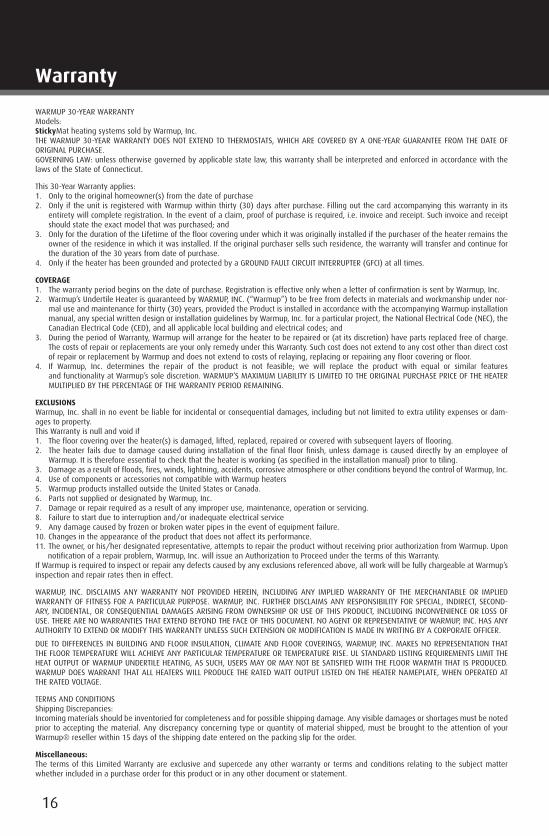
WARMUP 30-YEAR WARRANTY Models: StickyMat heating systems sold by Warmup, Inc. THE WARMUP 30-YEAR WARRANTY DOES NOT EXTEND TO THERMOSTATS, WHICH ARE COVERED BY A ONE-YEAR GUARANTEE FROM THE DATE OF ORIGINAL PURCHASE. GOVERNING LAW: unless otherwise governed by applicable state law, this warranty shall be interpreted and enforced in accordance with the laws of the State of Connecticut.
This 30-Year Warranty applies: 1. Only to the original homeowner(s) from the date of purchase 2. Only if the unit is registered with Warmup within thirty (30) days after purchase. Filling out the card accompanying this warranty in its
entirety will complete registration. In the event of a claim, proof of purchase is required, i.e. invoice and receipt. Such invoice and receipt should state the exact model that was purchased; and
3. Only for the duration of the Lifetime of the floor covering under which it was originally installed if the purchaser of the heater remains the owner of the residence in which it was installed. If the original purchaser sells such residence, the warranty will transfer and continue for the duration of the 30 years from date of purchase.
4. Only if the heater has been grounded and protected by a GROUND FAULT CIRCUIT INTERRUPTER (GFCI) at all times.
COVERAGE 1. The warranty period begins on the date of purchase. Registration is effective only when a letter of confirmation is sent by Warmup, Inc. 2. Warmup’s Undertile Heater is guaranteed by WARMUP, INC. (“Warmup”) to be free from defects in materials and workmanship under nor-
mal use and maintenance for thirty (30) years, provided the Product is installed in accordance with the accompanying Warmup installation manual, any special written design or installation guidelines by Warmup, Inc. for a particular project, the National Electrical Code (NEC), the Canadian Electrical Code (CED), and all applicable local building and electrical codes; and
3. During the period of Warranty, Warmup will arrange for the heater to be repaired or (at its discretion) have parts replaced free of charge. The costs of repair or replacements are your only remedy under this Warranty. Such cost does not extend to any cost other than direct cost of repair or replacement by Warmup and does not extend to costs of relaying, replacing or repairing any floor covering or floor.
4. If Warmup, Inc. determines the repair of the product is not feasible; we will replace the product with equal or similar features and functionality at Warmup’s sole discretion. WARMUP’S MAXIMUM LIABILITY IS LIMITED TO THE ORIGINAL PURCHASE PRICE OF THE HEATER MULTIPLIED BY THE PERCENTAGE OF THE WARRANTY PERIOD REMAINING.
EXCLUSIONS Warmup, Inc. shall in no event be liable for incidental or consequential damages, including but not limited to extra utility expenses or dam-ages to property. This Warranty is null and void if 1. The floor covering over the heater(s) is damaged, lifted, replaced, repaired or covered with subsequent layers of flooring. 2. The heater fails due to damage caused during installation of the final floor finish, unless damage is caused directly by an employee of
Warmup. It is therefore essential to check that the heater is working (as specified in the installation manual) prior to tiling. 3. Damage as a result of floods, fires, winds, lightning, accidents, corrosive atmosphere or other conditions beyond the control of Warmup, Inc.4. Use of components or accessories not compatible with Warmup heaters 5. Warmup products installed outside the United States or Canada. 6. Parts not supplied or designated by Warmup, Inc. 7. Damage or repair required as a result of any improper use, maintenance, operation or servicing. 8. Failure to start due to interruption and/or inadequate electrical service9. Any damage caused by frozen or broken water pipes in the event of equipment failure.10. Changes in the appearance of the product that does not affect its performance. 11. The owner, or his/her designated representative, attempts to repair the product without receiving prior authorization from Warmup. Upon
notification of a repair problem, Warmup, Inc. will issue an Authorization to Proceed under the terms of this Warranty.If Warmup is required to inspect or repair any defects caused by any exclusions referenced above, all work will be fully chargeable at Warmup’s inspection and repair rates then in effect.
WARMUP, INC. DISCLAIMS ANY WARRANTY NOT PROVIDED HEREIN, INCLUDING ANY IMPLIED WARRANTY OF THE MERCHANTABLE OR IMPLIED WARRANTY OF FITNESS FOR A PARTICULAR PURPOSE. WARMUP, INC. FURTHER DISCLAIMS ANY RESPONSIBILITY FOR SPECIAL, INDIRECT, SECOND-ARY, INCIDENTAL, OR CONSEQUENTIAL DAMAGES ARISING FROM OWNERSHIP OR USE OF THIS PRODUCT, INCLUDING INCONVENIENCE OR LOSS OF USE. THERE ARE NO WARRANTIES THAT EXTEND BEYOND THE FACE OF THIS DOCUMENT. NO AGENT OR REPRESENTATIVE OF WARMUP, INC. HAS ANY AUTHORITY TO EXTEND OR MODIFY THIS WARRANTY UNLESS SUCH EXTENSION OR MODIFICATION IS MADE IN WRITING BY A CORPORATE OFFICER.
DUE TO DIFFERENCES IN BUILDING AND FLOOR INSULATION, CLIMATE AND FLOOR COVERINGS, WARMUP, INC. MAKES NO REPRESENTATION THAT THE FLOOR TEMPERATURE WILL ACHIEVE ANY PARTICULAR TEMPERATURE OR TEMPERATURE RISE. UL STANDARD LISTING REQUIREMENTS LIMIT THE HEAT OUTPUT OF WARMUP UNDERTILE HEATING, AS SUCH, USERS MAY OR MAY NOT BE SATISFIED WITH THE FLOOR WARMTH THAT IS PRODUCED. WARMUP DOES WARRANT THAT ALL HEATERS WILL PRODUCE THE RATED WATT OUTPUT LISTED ON THE HEATER NAMEPLATE, WHEN OPERATED AT THE RATED VOLTAGE.
TERMS AND CONDITIONS Shipping Discrepancies: Incoming materials should be inventoried for completeness and for possible shipping damage. Any visible damages or shortages must be noted prior to accepting the material. Any discrepancy concerning type or quantity of material shipped, must be brought to the attention of your Warmup® reseller within 15 days of the shipping date entered on the packing slip for the order.
Miscellaneous: The terms of this Limited Warranty are exclusive and supercede any other warranty or terms and conditions relating to the subject matter whether included in a purchase order for this product or in any other document or statement.
Warranty

17

US Office:Warmup Inc
52 Federal Road, Unit 1FDanbury, CT, 06810
W: warmup.comE: [email protected]: (888) 927-6333F: (888) 927-4721
Canadian Office:Warmup Inc
374 Wellington St WToronto, ON, M5V 1E3
W: warmup.caE: [email protected]: (888) 592-7687F: (905) 366-7324
Complete and submit the warranty form online atwarmup.com (US) or warmup.ca (CAN)
v1.0 01/2015
Warmup Offices - North America


![Indoor Film Heating System INSTALLATION … MANUAL.pdfIndoor Film Heating System INSTALLATION MANUAL [ Floor : Under laminate floor ] ... GYUGj G G G](https://img.pdfslide.us/doc/110x75/5b88bdc37f8b9abe1e8befd3/indoor-film-heating-system-installation-manualpdfindoor-film-heating-system-installation.jpg)