Embed Size (px)
Citation preview
1
Sticks and Tissue No 68 – July 2012
If you can contribute any articles, wish to make your point of view known etc please send to or phone 01202
625825 [email protected]
The content does not follow any logical order or set out, it’s “as I put it in and receive”.
Thanks to Mark Venter back issues are available for download from
http://www.cmac.net.nz
Writings and opinions expressed are the opinion of the writer but not necessarily the compiler/publisher of
Sticks and Tissue.
Leon Cole with his Lanzo bomber at Sculthorpe in July
AUGUST BANK HOLIDAY MIDDLE
WALLOP HAS BEEN CANCELLED
2
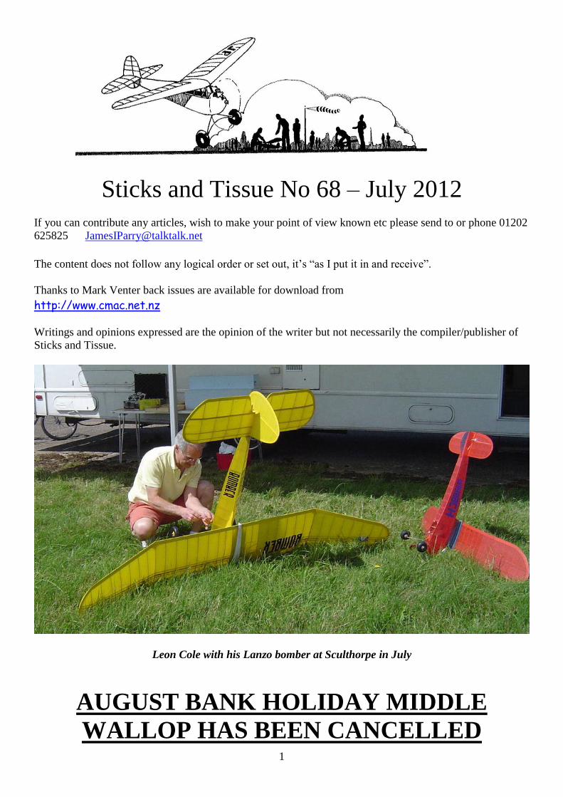
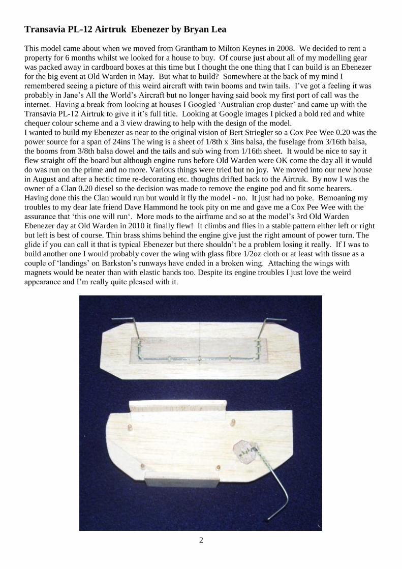
Transavia PL-12 Airtruk Ebenezer by Bryan Lea
This model came about when we moved from Grantham to Milton Keynes in 2008. We decided to rent a
property for 6 months whilst we looked for a house to buy. Of course just about all of my modelling gear
was packed away in cardboard boxes at this time but I thought the one thing that I can build is an Ebenezer
for the big event at Old Warden in May. But what to build? Somewhere at the back of my mind I
remembered seeing a picture of this weird aircraft with twin booms and twin tails. I’ve got a feeling it was
probably in Jane’s All the World’s Aircraft but no longer having said book my first port of call was the
internet. Having a break from looking at houses I Googled ‘Australian crop duster’ and came up with the
Transavia PL-12 Airtruk to give it it’s full title. Looking at Google images I picked a bold red and white
chequer colour scheme and a 3 view drawing to help with the design of the model.
I wanted to build my Ebenezer as near to the original vision of Bert Striegler so a Cox Pee Wee 0.20 was the
power source for a span of 24ins The wing is a sheet of 1/8th x 3ins balsa, the fuselage from 3/16th balsa,
the booms from 3/8th balsa dowel and the tails and sub wing from 1/16th sheet. It would be nice to say it
flew straight off the board but although engine runs before Old Warden were OK come the day all it would
do was run on the prime and no more. Various things were tried but no joy. We moved into our new house
in August and after a hectic time re-decorating etc. thoughts drifted back to the Airtruk. By now I was the
owner of a Clan 0.20 diesel so the decision was made to remove the engine pod and fit some bearers.
Having done this the Clan would run but would it fly the model - no. It just had no poke. Bemoaning my
troubles to my dear late friend Dave Hammond he took pity on me and gave me a Cox Pee Wee with the
assurance that ‘this one will run‘. More mods to the airframe and so at the model’s 3rd Old Warden
Ebenezer day at Old Warden in 2010 it finally flew! It climbs and flies in a stable pattern either left or right
but left is best of course. Thin brass shims behind the engine give just the right amount of power turn. The
glide if you can call it that is typical Ebenezer but there shouldn’t be a problem losing it really. If I was to
build another one I would probably cover the wing with glass fibre 1/2oz cloth or at least with tissue as a
couple of ‘landings’ on Barkston’s runways have ended in a broken wing. Attaching the wings with
magnets would be neater than with elastic bands too. Despite its engine troubles I just love the weird
appearance and I’m really quite pleased with it.
3
From Charlie Yost
If you like Oldtimers, you might like this one. All have sound. Enjoy.
Subject: Models 1936
www.youtube.com/watch?v=1VB8f-e17aU
4
5
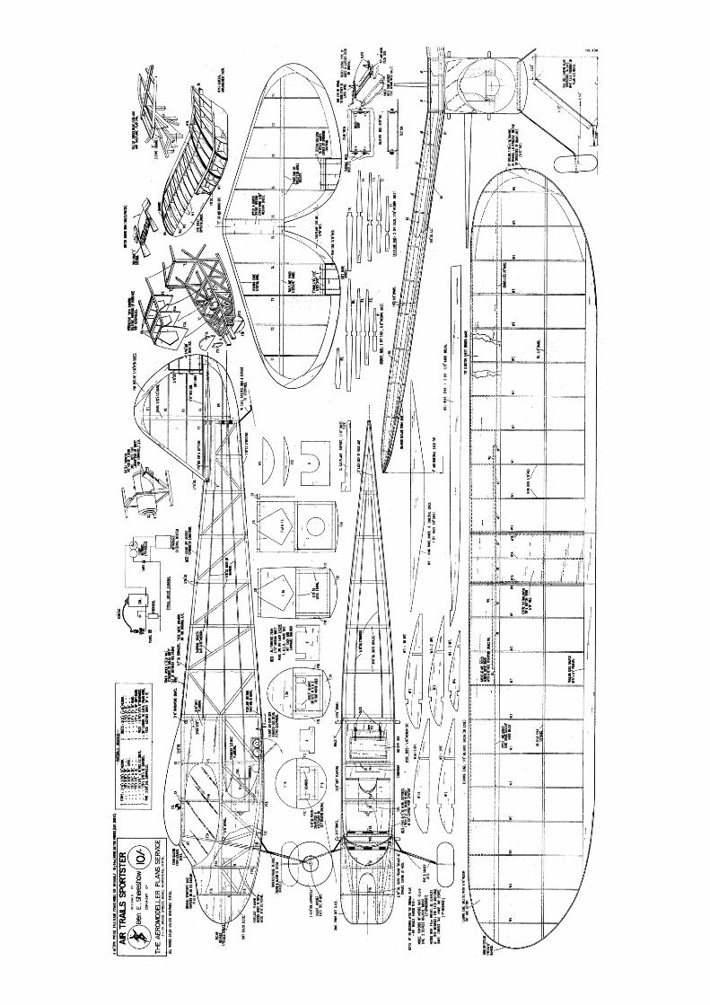
Air Trails Sportster a 46in design for free flight by Ben E Shereshaw.
In answer to many appeals for an attractive vintage model we revive a great favourite from pre-WW2
from the pages of “Ait Trails” From Aero Modeller March 1968
Twenty nine years old this month, this design represents a true vintage sports model for 3.5 cc. to answer the
innumerable requests we have had for vintage plans. Initially published in the American magazine Air
Trails, of fond memory, the Sportster introduced a new classification in engine capacity and started a series
of attractive cabin power models which were used for competition as well as fun flying through from 1939
to 1944. Who could deny that the lines are attractive? The vertical fin shape, which was to become the trade
mark of the many Ben Shereshaw designs subsequently kitted, the stringered fuselage, the large curving
transparent cabin area and the robustness of the structure characterised a model of an era which many old
timers hold in happy memory.
When it was introduced in Air Trails magazine, the Sportster was a small design for power, particularly
when one considers that only spark ignition could be used and the model had to carry the payload of a coil,
condenser and flight batteries. Ben Shereshaw had created what was then termed a “small bore” engine
which was to have been put out as a do-it-yourself magazine design. Named the “Bantam”, the engine
proved to be so popular and successful that Ben put into production and for many, this new .19 (3.25 cc.)
engine created a new engine capacity class and a new phase in model engine design. For the “Bantam”, in
terms of power to weight ratio was an exceptional product by any standards. It was practically the first rear
disc valve induction engine to go into mass production. It was extremely light in weight. It peaked very
happily at high r.p.m. on small diameter airscrews and when subsequently employed for the 1945 period
pylon model such as the Goldberg Intercepter, it was darned near invincible till the arrival of the Ardens and
accompanying Glowplugs.
So, in many ways, this model was a trail blazer and we are sure that by using a diesel to take advantage of
the short nose and to eliminate the weight of the batteries and coil, the Sportster will provide scintillating
performance today. The plan includes all the detail exactly as the original presented by Ben had in the
March 1939 Air Trails. This means that installation of battery box, coil, and relevant formers and bulkheads
as necessary, are provided for the vintage purists who believe in using nothing but the original material.
For those using a diesel or a glow engine, such details can be omitted.
As the designer was a perfectionist, his original instructions for assembly were also more complex than
those to which we have become accustomed. For example, he recommended the construction of a jig to hold
the longerons and diagonal members in place over the drawn positions on the plan whilst the parts were
assembled and the cement was drying. The jig was formed by tacking brads on either side of the
components; but nowadays, we have become used to using a soft board, household or steel pins and do not
go to the extent of using jigs. Assembly begins with fuselage sides by laying out the longerons and by fitting
all the diagonal and vertical cross members as can be seen in the side elevation. The sketch on the plan
clearly indicates how the cabin is subsequently made as a sub-assembly and the nose framework extends on
the basic sides along the line of the horizontal longerons only. Make two sides exactly the same, one over
the other, above the plan. When these are dry, they must be joined by the cross members as indicated in the
plan view. Start joining the fuselage sides at the cabin area where the width is constant, fitting former C at
the third spacer position and this will be found to keep the assembly square. Draw the nose together and then
the tail, fitting the intermediate cross members at each point as indicated in the plan view. Use plenty of
elastic bands to draw the longerons in at the nose for the rather sharp curve at Fl. Formers A and B should
also be fitted to help keep the nose assembly square but first check the slot spacing for your engine bearers,
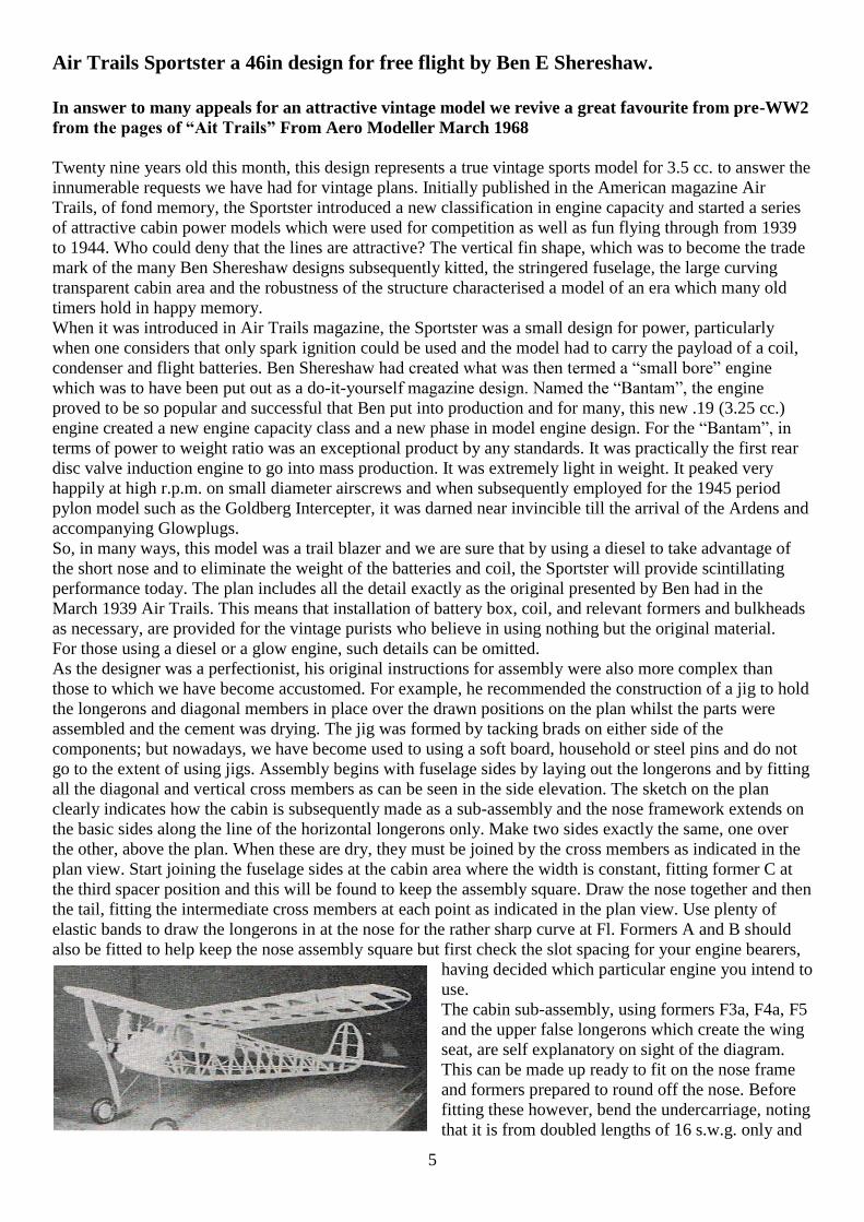
having decided which particular engine you intend to
use.
The cabin sub-assembly, using formers F3a, F4a, F5
and the upper false longerons which create the wing
seat, are self explanatory on sight of the diagram.
This can be made up ready to fit on the nose frame
and formers prepared to round off the nose. Before
fitting these however, bend the undercarriage, noting
that it is from doubled lengths of 16 s.w.g. only and
6
bind securely to the cross members at F3b and F3c positions. It should be noted that air wheels are specified
on the plans as used during the 1939 period. These pneumatic wheels absorbed a lot of the landing loads and
hence there was little need for a very rigid heavy gauge undercarriage wire. Those who intend to use solid
wheels should increase the wire diameter to 14 s,w.g. When the nose formers are fitted, the cabin is sheeted
and nose blocks prepared to provide the shape to suit the engine. A tank can be positioned in the area near
F2a and fuel shut off and modern timer accommodated according to one’s modern whims. It should be noted
that the original timer which interrupted the circuit for the coil and condenser was positioned above the
fuselage, and behind the wing trailing edge. This was a
normal position since most flights started by taking off on the undercarriage from the ground.
The tail surfaces should be the next task. The structure is rather like that introduced by the Californian Radio
Control enthusiasts in, for example, the “Smog Hog” design by Howard Bonner. The similarity ends when
one begins to study the weight of the structure! In each case for the fin or the tail-plane, the lower spar is
laid down first over the position on the drawing and the ribs cemented in place on the spars. Make sure they
maintain proper alignment. The eighth balsa outline is then cemented in place, jigging it up with scrap balsa
over the building board in order that it meets the rib centre lines properly. The outline should be roughly pre
carved to the airfoil contour before making this joint in order not to strain the structure too much after it has
been assembled. The upper spar can then be fitted and when thoroughly dry, the assembly lifted from the
plan, and in the case of tailplane, the centre section sheeted. It is recommended that the spar on the tailplane
could be boxed in with webs on either side for added rigidity, and the builder should also pay attention to the
recommendation for the “T” section false spars to support the trim tab hinges. The tail assembly is
deliberately kept light particularly in view of the short nose moment. For this reason, one should choose
only soft balsa wood or the 3/16 in. thick trim tabs.
Study the wing structure carefully before tackling this most important part of the model. Note that the
centre section is flat, to seat on the cabin super structure and there is plain dihedral out to the tips. This
amounts to three inches under each tip as shown in the front view. The wing panel joiner and dihedral brace
as well as the spar pattern are given full size on the drawing for the sake of accuracy. Cut these parts
carefully and make sure that the contours are correct.
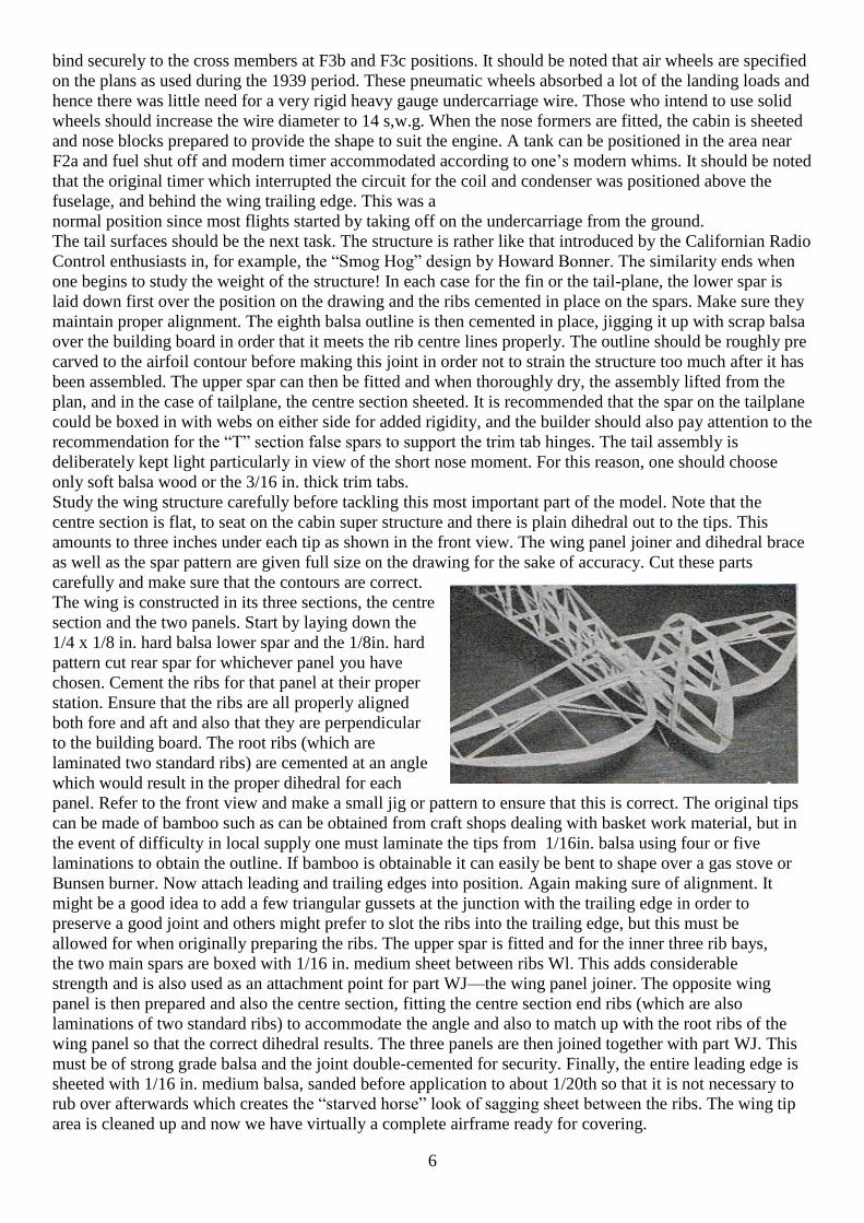
The wing is constructed in its three sections, the centre
section and the two panels. Start by laying down the
1/4 x 1/8 in. hard balsa lower spar and the 1/8in. hard
pattern cut rear spar for whichever panel you have
chosen. Cement the ribs for that panel at their proper
station. Ensure that the ribs are all properly aligned
both fore and aft and also that they are perpendicular
to the building board. The root ribs (which are
laminated two standard ribs) are cemented at an angle
which would result in the proper dihedral for each
panel. Refer to the front view and make a small jig or pattern to ensure that this is correct. The original tips
can be made of bamboo such as can be obtained from craft shops dealing with basket work material, but in
the event of difficulty in local supply one must laminate the tips from 1/16in. balsa using four or five
laminations to obtain the outline. If bamboo is obtainable it can easily be bent to shape over a gas stove or
Bunsen burner. Now attach leading and trailing edges into position. Again making sure of alignment. It
might be a good idea to add a few triangular gussets at the junction with the trailing edge in order to
preserve a good joint and others might prefer to slot the ribs into the trailing edge, but this must be
allowed for when originally preparing the ribs. The upper spar is fitted and for the inner three rib bays,
the two main spars are boxed with 1/16 in. medium sheet between ribs Wl. This adds considerable
strength and is also used as an attachment point for part WJ—the wing panel joiner. The opposite wing
panel is then prepared and also the centre section, fitting the centre section end ribs (which are also
laminations of two standard ribs) to accommodate the angle and also to match up with the root ribs of the
wing panel so that the correct dihedral results. The three panels are then joined together with part WJ. This
must be of strong grade balsa and the joint double-cemented for security. Finally, the entire leading edge is
sheeted with 1/16 in. medium balsa, sanded before application to about 1/20th so that it is not necessary to
rub over afterwards which creates the “starved horse” look of sagging sheet between the ribs. The wing tip
area is cleaned up and now we have virtually a complete airframe ready for covering.
7
The original aircraft was covered in a light shade of what was then called Bamboo tissue, the nearest
equivalent today being wet strengthened Modeispan. Three coats of dope was applied to the colour tissue
of the original. No records have been retained of the weight of the original model but the reader may take it
from us that it was light by modern standards. Obviously the performance of such a model will be improved
by weight saving and careful construction throughout, in fact the Sportster represents a very interesting
structural assembly challenge for the modern modeller. The provision of trim tabs on the tail surfaces and
Ben’s rule of thumb recommendation for correcting the tail angle according to the weight of the engine
(motors over 3 ounces should demand minus 1 deg. incidence for each additional ounce), make for a
very easily trimmed design. We know from letter requests how many modellers will appreciate this
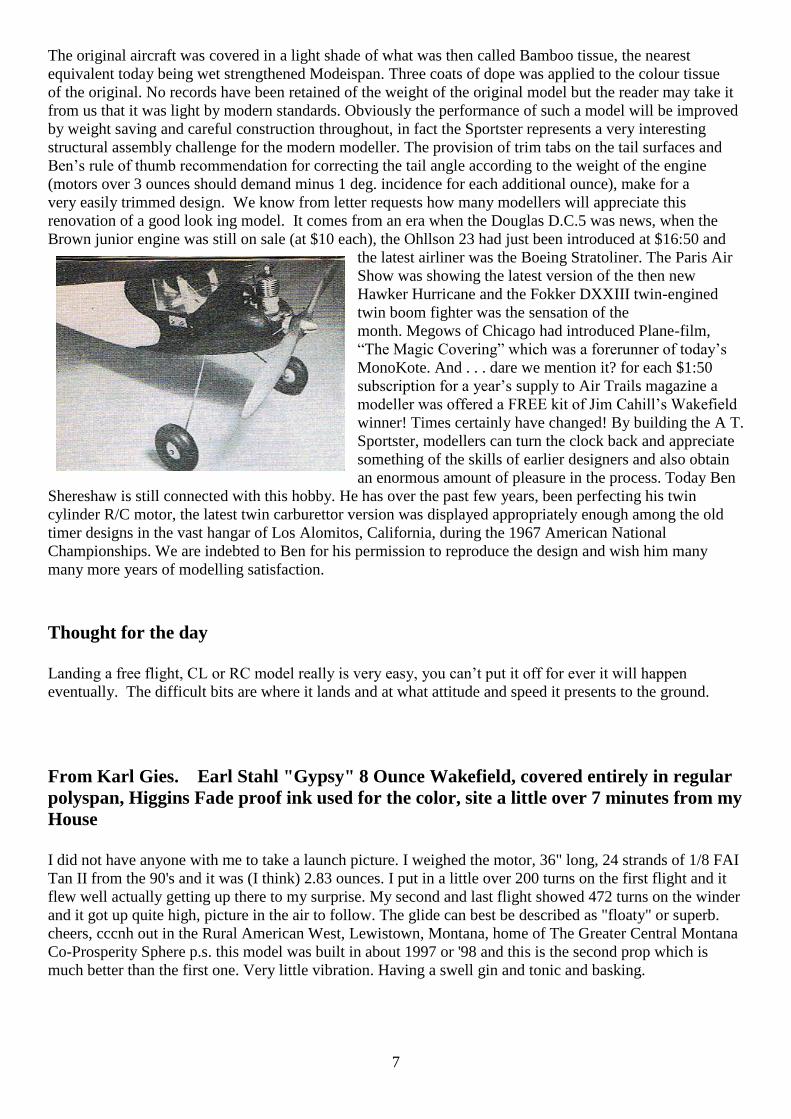
renovation of a good look ing model. It comes from an era when the Douglas D.C.5 was news, when the
Brown junior engine was still on sale (at $10 each), the Ohllson 23 had just been introduced at $16:50 and
the latest airliner was the Boeing Stratoliner. The Paris Air
Show was showing the latest version of the then new
Hawker Hurricane and the Fokker DXXIII twin-engined
twin boom fighter was the sensation of the
month. Megows of Chicago had introduced Plane-film,
“The Magic Covering” which was a forerunner of today’s
MonoKote. And . . . dare we mention it? for each $1:50
subscription for a year’s supply to Air Trails magazine a
modeller was offered a FREE kit of Jim Cahill’s Wakefield
winner! Times certainly have changed! By building the A T.
Sportster, modellers can turn the clock back and appreciate
something of the skills of earlier designers and also obtain
an enormous amount of pleasure in the process. Today Ben
Shereshaw is still connected with this hobby. He has over the past few years, been perfecting his twin
cylinder R/C motor, the latest twin carburettor version was displayed appropriately enough among the old
timer designs in the vast hangar of Los Alomitos, California, during the 1967 American National
Championships. We are indebted to Ben for his permission to reproduce the design and wish him many
many more years of modelling satisfaction.
Thought for the day
Landing a free flight, CL or RC model really is very easy, you can’t put it off for ever it will happen
eventually. The difficult bits are where it lands and at what attitude and speed it presents to the ground.
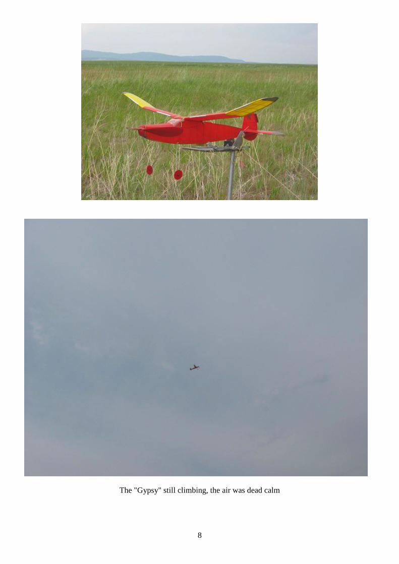
From Karl Gies. Earl Stahl "Gypsy" 8 Ounce Wakefield, covered entirely in regular
polyspan, Higgins Fade proof ink used for the color, site a little over 7 minutes from my
House
I did not have anyone with me to take a launch picture. I weighed the motor, 36" long, 24 strands of 1/8 FAI
Tan II from the 90's and it was (I think) 2.83 ounces. I put in a little over 200 turns on the first flight and it
flew well actually getting up there to my surprise. My second and last flight showed 472 turns on the winder
and it got up quite high, picture in the air to follow. The glide can best be described as "floaty" or superb.
cheers, cccnh out in the Rural American West, Lewistown, Montana, home of The Greater Central Montana
Co-Prosperity Sphere p.s. this model was built in about 1997 or '98 and this is the second prop which is
much better than the first one. Very little vibration. Having a swell gin and tonic and basking.
8
The "Gypsy" still climbing, the air was dead calm
9
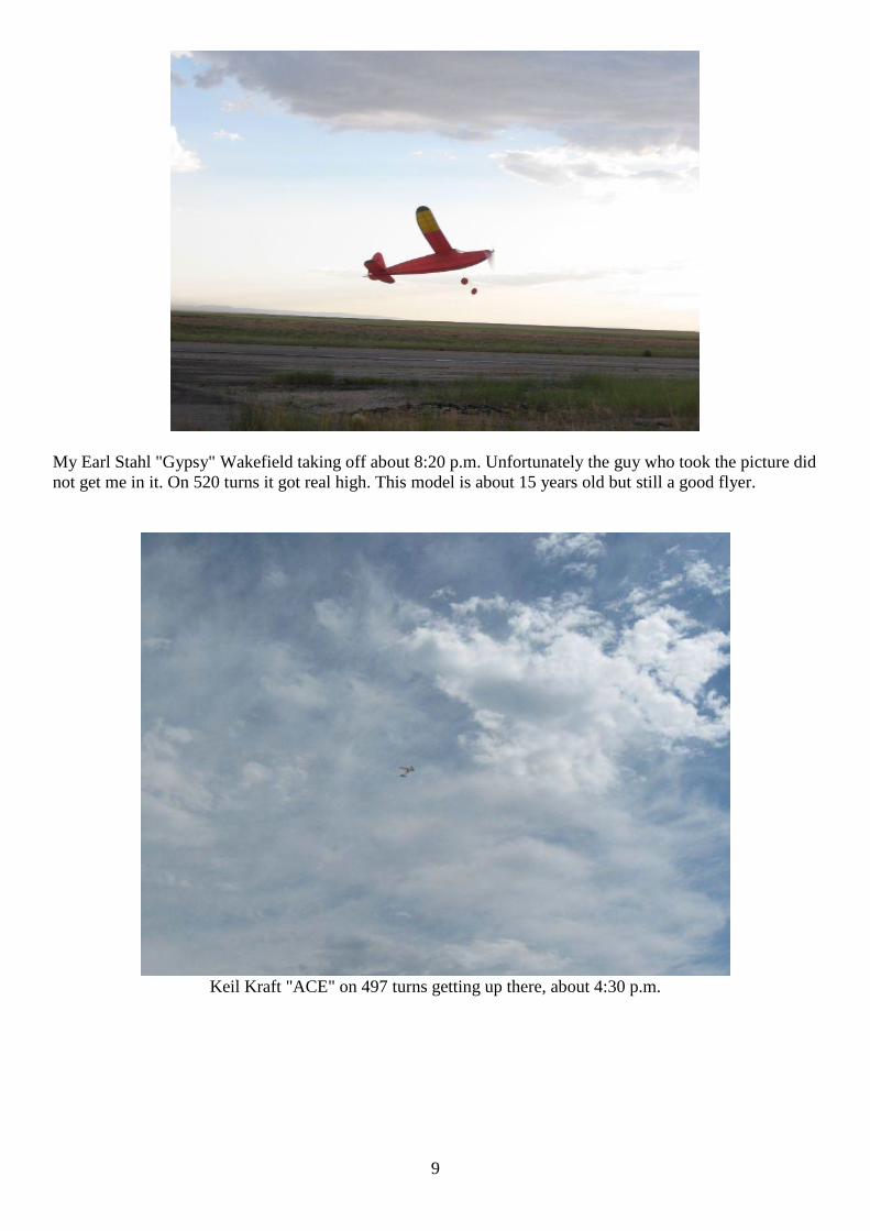
My Earl Stahl "Gypsy" Wakefield taking off about 8:20 p.m. Unfortunately the guy who took the picture did
not get me in it. On 520 turns it got real high. This model is about 15 years old but still a good flyer.
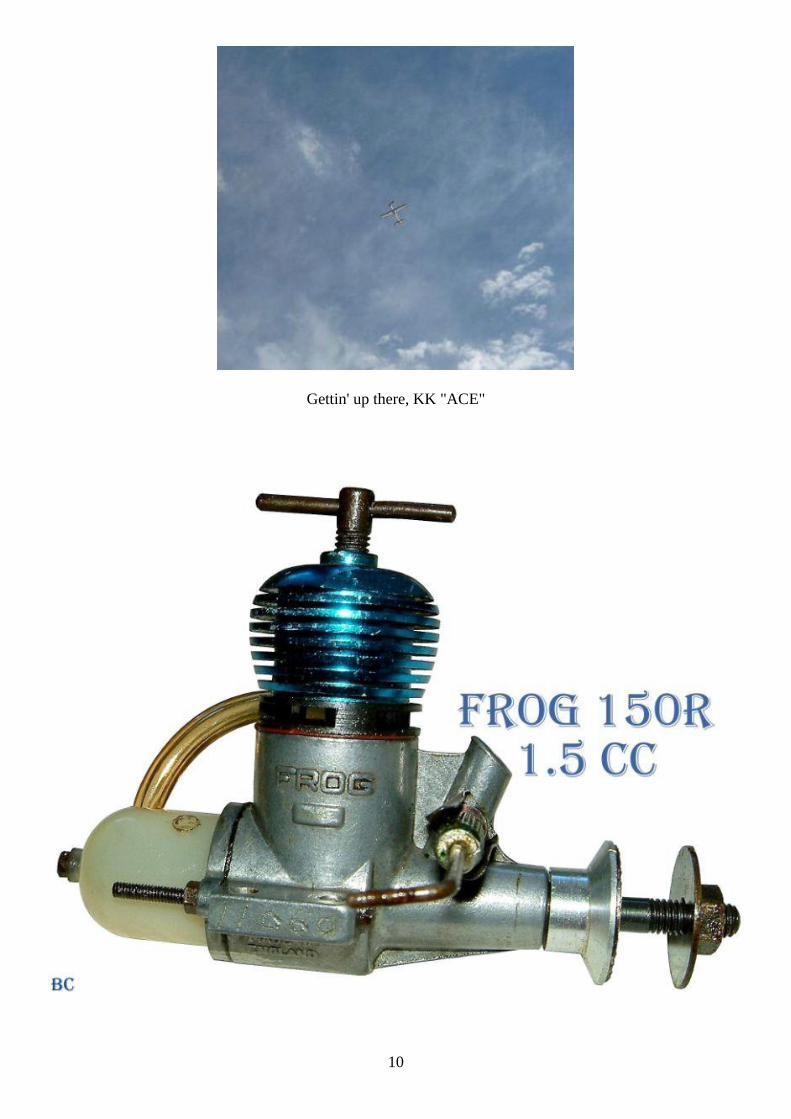
Keil Kraft "ACE" on 497 turns getting up there, about 4:30 p.m.
10
Gettin' up there, KK "ACE"
11
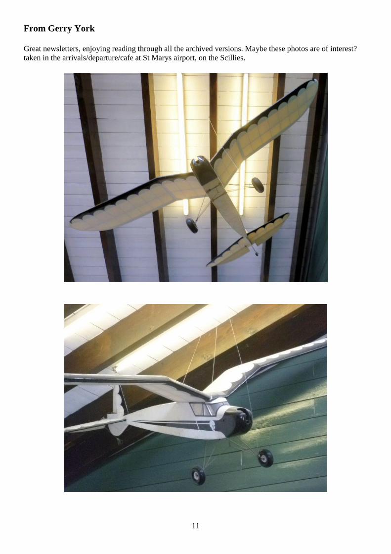
From Gerry York
Great newsletters, enjoying reading through all the archived versions. Maybe these photos are of interest?
taken in the arrivals/departure/cafe at St Marys airport, on the Scillies.
12
SAM 35 Vintage Power Duration, 21,22 July 2012 East Anglia Gala, Sculthorpe
From Bill Longley
The weekend was the best of the year so far, the Saturday was blessed with the best of weather, very light
wind with much thermal activity. The Sunday was overcast and blustery in the morning, but cleared later in
the day.
The entrants enjoyed the terrific conditions, the top 4 all achieving 2max’s each from the 3 classified flights.
With possibility of being able to enter in 6 different classes ( Contest / Sport, and 3 engine size categories ),
multiple entries were acceptable from each competitor. Total of 11 entries were received from 5 individual
contestants
In the contest classes :-
Bill Longley flew Starduster 600 / Torp 19 ( Old Faithful )
Wes Denton flew his TD .09 powered Jumpin’ Bean .
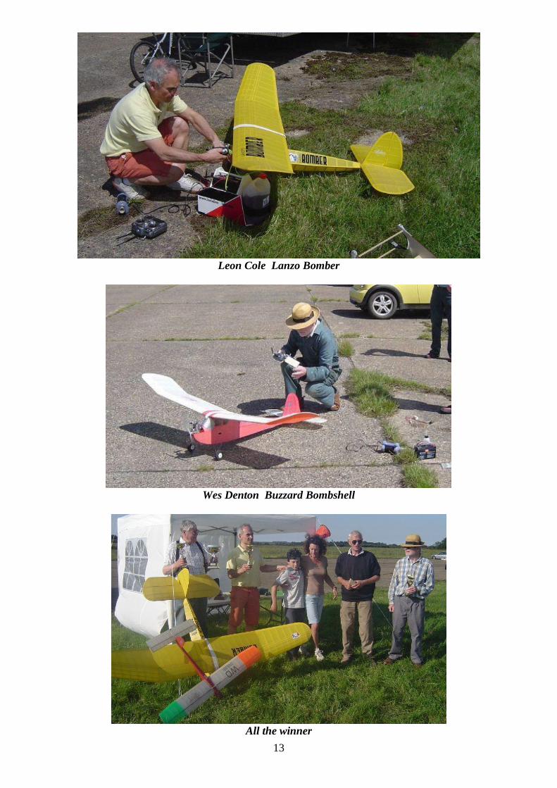
Leon Cole flew 96” Lanzo Bomber, OS 65 4-str. ( built from Belair kit ) Roger Hollett also flew a
Bomber, as above. David Bell from Hull entered an Alert, but did not record a score. Bill Longley also flew
his Payee Max, but having completed an easy 2 max’s had problems bringing the model down from the
abundant lift, and the model unfortunately spiralled into the concrete due to what was later ascertained as a
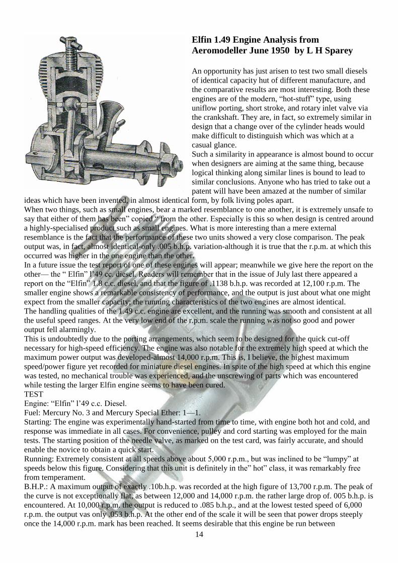
flat battery. The Sport Class had Wesley Denton flying his Belair Kits Buzzard Bombshell powered by a
Saito 62 4 stroke. An incident just before the start of the competition being hit and damaged by another
competitors model, damage was sustained to the cabin area, but not to the flying surfaces, and did complete
3 flights in the Sport class. Mid morning a wind gust did pickup the Gazebo control tent, this rolled over
onto Bill Longley’s Super Creep, damaging the tailplane mount , rendering it not flyable..
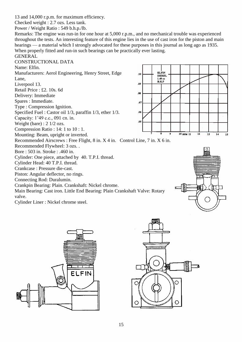
Prizeware was given out by Mrs Cole, wife of Leon.
SCORES Engine run allowed Total time secs ( 3 flights )
Contest Class
1st Bill Longley 20 889
2nd Wes Denton 20 825
3rd Leon Cole 15 814
Class win Roger Hollett 15 741
Sport Class Wes Denton 22 713.
Leon Cole with his large 96” Belair Kits LANZO BOMBER gave some very impressive flights, 15 second
engine run allowance on the OS 65 4-stroke gave climb height of 500 – 600 feet. This model then showed
that it could detect lift with the greatest of ease, of particular note, the ability to perform flat turns on a
sixpence without loss of any height, wings rocking at the slightest of detected air movement
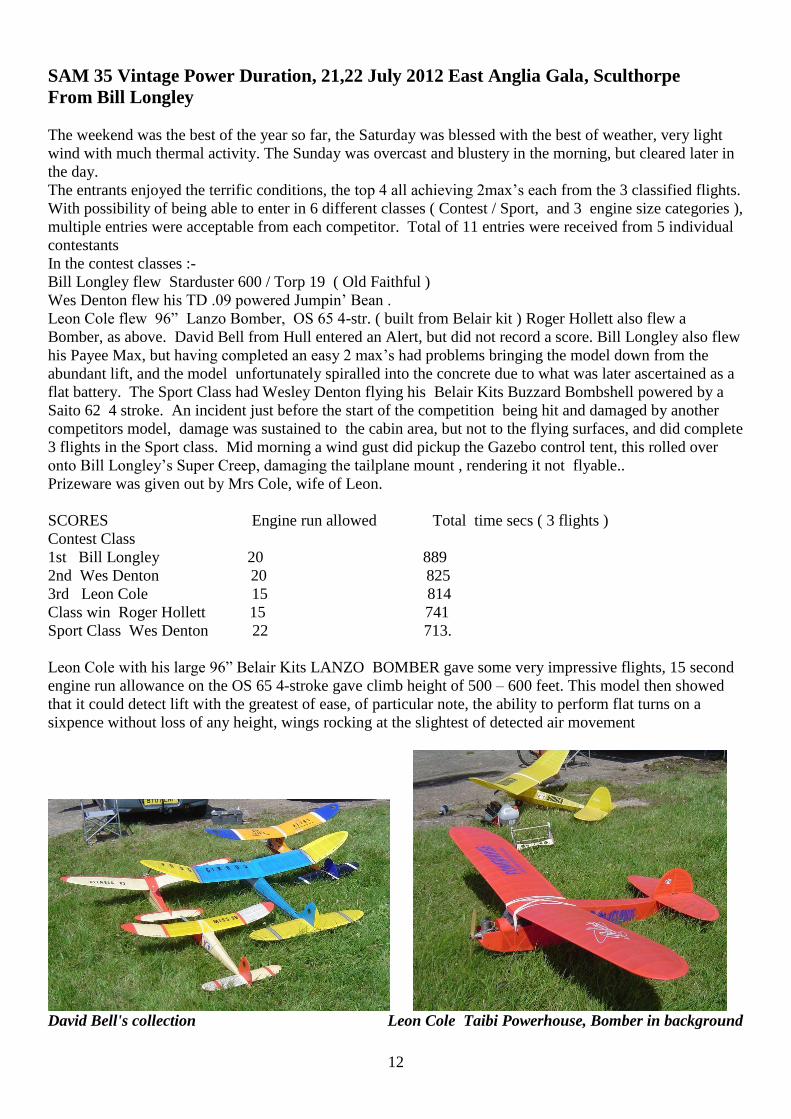
David Bell's collection Leon Cole Taibi Powerhouse, Bomber in background
13
Leon Cole Lanzo Bomber
Wes Denton Buzzard Bombshell
All the winner
14
Elfin 1.49 Engine Analysis from
Aeromodeller June 1950 by L H Sparey
An opportunity has just arisen to test two small diesels
of identical capacity hut of different manufacture, and
the comparative results are most interesting. Both these
engines are of the modern, “hot-stuff” type, using
uniflow porting, short stroke, and rotary inlet valve via
the crankshaft. They are, in fact, so extremely similar in
design that a change over of the cylinder heads would
make difficult to distinguish which was which at a
casual glance.
Such a similarity in appearance is almost bound to occur
when designers are aiming at the same thing, because
logical thinking along similar lines is bound to lead to
similar conclusions. Anyone who has tried to take out a
patent will have been amazed at the number of similar
ideas which have been invented, in almost identical form, by folk living poles apart.
When two things, such as small engines, bear a marked resemblance to one another, it is extremely unsafe to
say that either of them has been” copied “ from the other. Especially is this so when design is centred around
a highly-specialised product such as small engines. What is more interesting than a mere external
resemblance is the fact that the performance of these two units showed a very close comparison. The peak
output was, in fact, almost identical-only .005 b.h.p. variation-although it is true that the r.p.m. at which this
occurred was higher in the one engine than the other.
In a future issue the test report of one of these engines will appear; meanwhile we give here the report on the
other— the “ Elfin” l’49 cc. diesel. Readers will remember that in the issue of July last there appeared a
report on the “Elfin” 1.8 c.c. diesel, and that the figure of .1138 b.h.p. was recorded at 12,100 r.p.m. The
smaller engine shows a remarkable consistency of performance, and the output is just about what one might
expect from the smaller capacity; the running characteristics of the two engines are almost identical.
The handling qualities of the 1.49 c.c. engine are excellent, and the running was smooth and consistent at all
the useful speed ranges. At the very low end of the r.p.m. scale the running was not so good and power
output fell alarmingly.
This is undoubtedly due to the porting arrangements, which seem to be designed for the quick cut-off
necessary for high-speed efficiency. The engine was also notable for the extremely high speed at which the
maximum power output was developed-almost 14,000 r.p.m. This is, I believe, the highest maximum
speed/power figure yet recorded for miniature diesel engines. In spite of the high speed at which this engine
was tested, no mechanical trouble was experienced, and the unscrewing of parts which was encountered
while testing the larger Elfin engine seems to have been cured.
TEST
Engine: “Elfin” l’49 c.c. Diesel.
Fuel: Mercury No. 3 and Mercury Special Ether: 1—1.
Starting: The engine was experimentally hand-started from time to time, with engine both hot and cold, and
response was immediate in all cases. For convenience, pulley and cord starting was employed for the main
tests. The starting position of the needle valve, as marked on the test card, was fairly accurate, and should
enable the novice to obtain a quick start.
Running: Extremely consistent at all speeds above about 5,000 r.p.m., but was inclined to be “lumpy” at
speeds below this figure. Considering that this unit is definitely in the” hot” class, it was remarkably free
from temperament.
B.H.P.: A maximum output of exactly .10b.h.p. was recorded at the high figure of 13,700 r.p.m. The peak of
the curve is not exceptionally flat, as between 12,000 and 14,000 r.p.m. the rather large drop of. 005 b.h.p. is
encountered. At 10,000 r.p.m. the output is reduced to .085 b.h.p., and at the lowest tested speed of 6,000
r.p.m. the output vas only .053 b.h.p. At the other end of the scale it will be seen that power drops steeply
once the 14,000 r.p.m. mark has been reached. It seems desirable that this engine be run between
15
13 and 14,000 r.p.m. for maximum efficiency.
Checked weight : 2.7 ozs. Less tank.
Power / Weight Ratio : 549 b.h.p./lb.
Remarks: The engine was run-in for one hour at 5,000 r.p.m., and no mechanical trouble was experienced
throughout the tests. An interesting feature of this engine lies in the use of cast iron for the piston and main
hearings — a material which I strongly advocated for these purposes in this journal as long ago as 1935.
When properly fitted and run-in such bearings can be practically ever lasting.
GENERAL
CONSTRUCTIONAL DATA
Name: Elfin.
Manufacturers: Aerol Engineering, Henry Street, Edge
Lane,
Liverpool 13.
Retail Price : £2. 10s. 6d
Delivery: Immediate
Spares : Immediate.
Type : Compression Ignition.
Specified Fuel : Castor oil 1/3, paraffin 1/3, ether 1/3.
Capacity: 1’49 c.c., 091 cn. in.
Weight (bare) : 2 1/2 ozs.
Compression Ratio : 14: 1 to 10 : 1.
Mounting: Beam, upright or inverted.
Recommended Airscrews : Free Flight, 8 in. X 4 in. Control Line, 7 in. X 6 in.
Recommended Flywheel: 3 ozs. .
Bore : 503 in. Stroke : .460 in.
Cylinder: One piece, attached by 40. T.P.I. thread.
Cylinder Head: 40 T.P.I. thread.
Crankcase : Pressure die-cast.
Piston: Angular deflector, no rings.
Connecting Rod: Duralumin.
Crankpin Bearing: Plain. Crankshaft: Nickel chrome.
Main Bearing: Cast iron. Little End Bearing: Plain Crankshaft Valve: Rotary
valve.
Cylinder Liner : Nickel chrome steel.
16
17
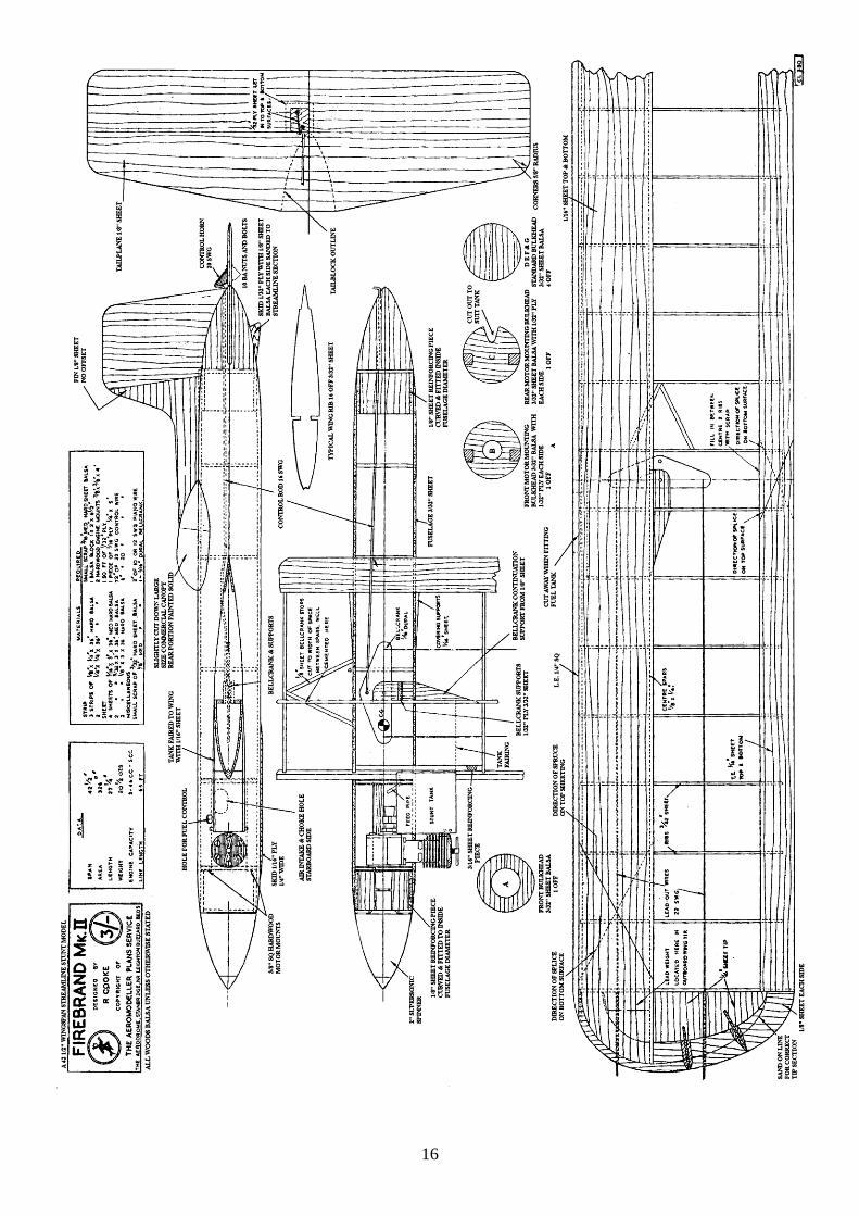
Firebrand a 42 ½” wingspan streamline stunt
model designed by Ralph Cooke from
Aeromodeller June 1950
Presenting a new form of tubular balsa fuselage
construction, the Firebrand is a fast flying stunter suited
to the latest 3.5 C.C. to 5 c.c. motors.. Its sleek lines are
apt to mislead one into thinking in terms of frailty,
whereas it has proven tough beyond comparison with
other standard forms of structure.
We have seen wound sheet, planked and commercial
paper-bound sheet used on other control-liners and free
flighters, but this wrapped construction is different. Firstly, it allows the” works “to be put inside with the
least difficulty (ever tangled the push-pull rod with the formers in a planked job ?), and secondly, it’s the
quickest built all-balsa fuselage, outside the crude box type.
Building Instructions. Firebrand is built in three stages. First make the fuselage halves, then the wings and
tailplane and, finally, assemble the whole in strict sequence.
Fuselage Halves. Find a round former of approximate fuselage diameter. Cut out from 3/32 in. medium
sheet balsa two fuselage halves 3 1/4 in. wide and of exact length. Mark all bulkhead positions on the inside
surfaces and steam the outside surface. During the steaming, the side will naturally curve, so place it on the
former occasionally to check that it will bend the full curve without forcing. When sufficiently bent lay the
side on the former and either pin or wind tight with a piece of elastic. Dry the curved balsa near a fire for ten
minutes and then repeat the process for the second half. Cut out all bulkheads and halve each, with the
exception of B and C (the two supporting the engine mountings). Cut out the portion occupied by the wing
in each half and cement each bulkhead firmly in its correct place. Bulging between bulkheads can be
removed by a skin of cement to pull in the offensive spot. Cement in place the 1/8 in, soft sheet reinforcing
pieces at the nose and tail, which are formed in the same way as the fuselage side. These can be made with 3
in. wide balsa plus a small strip for packing. Cut out the plan view of the tail block from 1/8 in. sheet, and
cement temporarily to each side of it a block of 1x2 in. soft balsa, with the grain fore and aft. Mark out the
diameter of the fuselage on one end and sand and carve the block to shape. Separate the halves from the 1/8
in. centre core and cut a strip approximately 1/8 in. wide across the forward end of the core. Now pin all
three together again, using this strip instead of the full plan- view of the core. (This allows easy fitting of the
tailpiane.) Fasten the two fuselage halves together with elastic bands and cement the tail blocks to the
fuselage, checking that the slot for the tailplane coincides with the dividing line between the two halves.
When firm, separate the two halves and carve the rear ends to merge into the tail blocks.
Mainplane. Cut the ribs from 3/32 in sheet and sandwich eight between two 1/32 in. plywood templates, to
position the holes for the lead out wires. Cut the leading edge, spars, and trailing edge pieces from hard balsa
and begin to construct the wing by pinning a spar to the plan view, noting that the spar must be raised 1/16
in. off the board for correct alignment. Assemble the ribs to the spar, add the upper spar, the trailing edge top
and the leading edges. When set, remove from the plan and add the bottom trailing edge piece. Check for
warps as the wing is assembled. Add the wing tips.
Cut back the inboard centre rib 3/16 in. and fit the leading edge reinforcing piece of 3/16 in. sheet, which is
1/4 in. deep at the front and 3/8 in. deep at the rear, conforming with the wing section. Make up the
bellcrank assembly of ply faced 3/32 in. balsa and fit in position between the centre spars. The bellcrank is
of dural pivoted with a piece of heavy gauge steel wire which is cemented in place after the lead-outs are
fixed, and soldered with cupwashers at the bellcrank end. Add other strengthening supports. The lead weight
on the out board tip must be very firmly fixed, and should balance the model laterally at a point 1 in
outboard of the fuselage centre line. Complete the wing by covering the leading edge portion with 1/16 in.
sheet, noting the splice position on the plan. The Tailplane and Elevator are of sheet and cut as per plan.
Final Assembly. Carve the outer faces of the engine mounts to the section shown and assemble complete
with engine on to the bulkheads, glueing the whole unit firmly into the fuselage lower half. Remove the
engine and give all exposed parts a coat of thick coloured dope to resist oil. Adjust the venture tube and
needle valve assembly, so that the needle projects through the upper fuselage half at the correct angle of
approximately 45°, sloping towards the inside of the circle. While the motor unit assembly is drying in the
18
lower half, alter the large size “F. Guest” stunt tank by unsweating the feed pipe and sealing hole. Enter
another feed pipe as shown in the drawing. Cover the tank with rag tissue so that it can be cemented in place
on the fuselage. Fit the wing to the lower half of the fuselage, cutting away the leading edge for the tank.
Check the fit of the top half over the wing and sand the fuselage as necessary. Now fix the mainplane in
position with pins, and temporarily mount the tailplane in order to bend the control rod to accurate length. It
will be necessary to cut away the bulkheads and the tail block in the upper half for control rod clearance.
Check any tendency to twist in the fuselage and make sure that the wing and tailplane are both neutral to the
thrust lines. Cut out from the top half, the access holes for choking, needle valve, and to give a good fit
round the engine. With the engine firmly fixed glue the wings to the lower half and then add the tailplane
and upper fuselage halves completing the assembly by adding the fin. Remember that each of these joints is
important and should be pre cemented. The tank may be streamlined into the mainplane with 1/16 in. sheet.
Prepare the model for covering and coat all exposed balsa parts liberally with sanding sealer, then cover with
llghtweight “Modelspan “. After doping, colour the model to your requirements with “Aerolac “.
To fit a drop-out undercarriage, drill holes may be drilled for prong fittings through the balsa centre of the
bulkhead “B.” Line length on the original was 65 ft., using light Lay-strate.
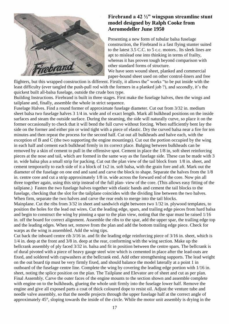
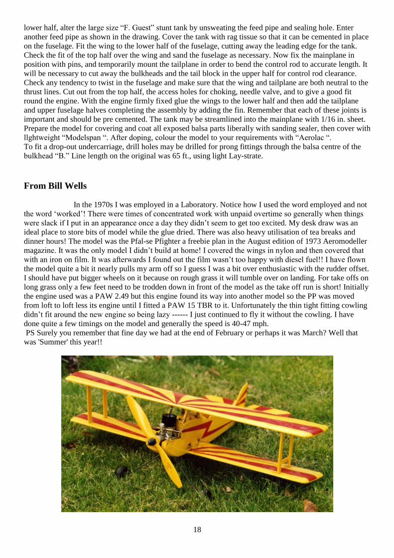
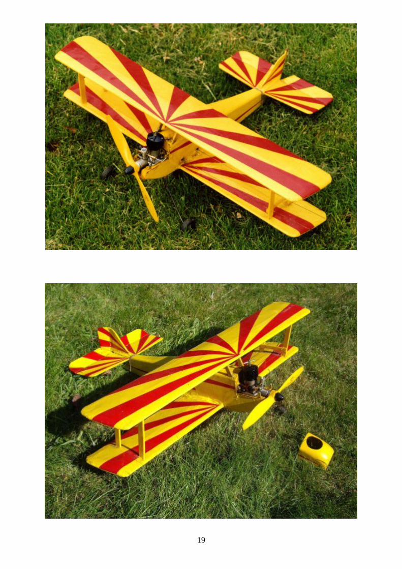
From Bill Wells
In the 1970s I was employed in a Laboratory. Notice how I used the word employed and not
the word ‘worked’! There were times of concentrated work with unpaid overtime so generally when things
were slack if I put in an appearance once a day they didn’t seem to get too excited. My desk draw was an
ideal place to store bits of model while the glue dried. There was also heavy utilisation of tea breaks and
dinner hours! The model was the Pfal-se Pfighter a freebie plan in the August edition of 1973 Aeromodeller
magazine. It was the only model I didn’t build at home! I covered the wings in nylon and then covered that
with an iron on film. It was afterwards I found out the film wasn’t too happy with diesel fuel!! I have flown
the model quite a bit it nearly pulls my arm off so I guess I was a bit over enthusiastic with the rudder offset.
I should have put bigger wheels on it because on rough grass it will tumble over on landing. For take offs on
long grass only a few feet need to be trodden down in front of the model as the take off run is short! Initially
the engine used was a PAW 2.49 but this engine found its way into another model so the PP was moved
from loft to loft less its engine until I fitted a PAW 15 TBR to it. Unfortunately the thin tight fitting cowling
didn’t fit around the new engine so being lazy ------ I just continued to fly it without the cowling. I have
done quite a few timings on the model and generally the speed is 40-47 mph.
PS Surely you remember that fine day we had at the end of February or perhaps it was March? Well that
was 'Summer' this year!!
19
20
21
David Kinsella’s Column
Perfect Ear
Time slips away and already Dick Roberts has published 31 columns of his Engine Ear, each bulging with
info and pictures we return to with joy. Hot bikes appear as well as McCoys and Doolings, at summer’s
close a 125cc MV from those drum brake days of Hailwood and Aggo, Read and Duke. Close to the track in
those freedom days, Stanley Schofield recorded all the cars and bikes in action and released several records
in arresting sleeves worthy of display in the den. An utter treat is the Mercedes W125 at Oulton Park,
Collins and Brooks storming round in the Silver Arrow. NB: caught once, check that disc and sleeve match!
Big Problem
Robert Aickman (1914—1981), scribe of spooky stuff arid a founder of the Inland Waterways Association,
said that with the Industrial/Energy Revolution that kicked off wìth cotton spinning over here, we turned in
the wrong direction and closed on even, greater problems than before. Right now most are cutting back but
the economy needs extra spending to get it going. How do you square that? Robert‘s grandfather wrote The
Beetle, at the time said to rival Dracula as a creepy tale.
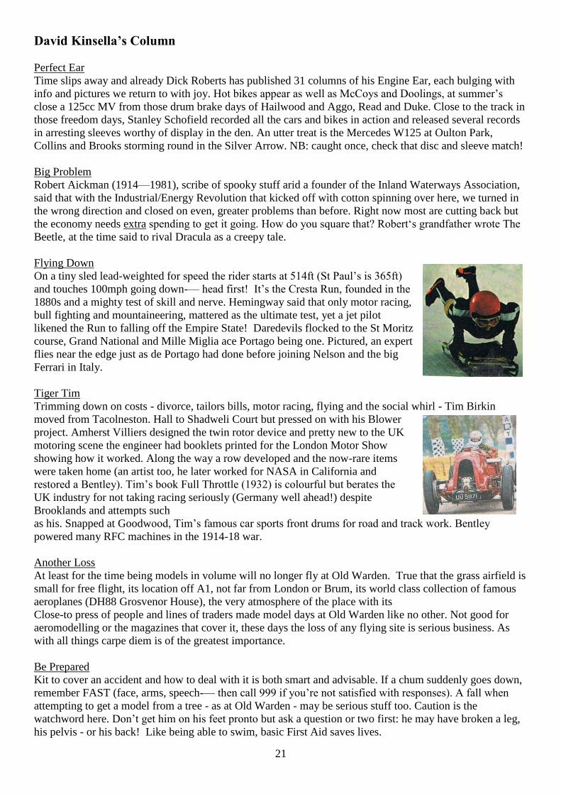
Flying Down
On a tiny sled lead-weighted for speed the rider starts at 514ft (St Paul’s is 365ft)
and touches 100mph going down-— head first! It’s the Cresta Run, founded in the
1880s and a mighty test of skill and nerve. Hemingway said that only motor racing,
bull fighting and mountaineering, mattered as the ultimate test, yet a jet pilot
likened the Run to falling off the Empire State! Daredevils flocked to the St Moritz
course, Grand National and Mille Miglia ace Portago being one. Pictured, an expert
flies near the edge just as de Portago had done before joining Nelson and the big
Ferrari in Italy.
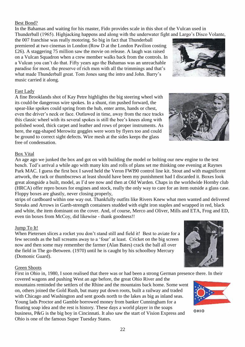
Tiger Tim
Trimming down on costs - divorce, tailors bills, motor racing, flying and the social whirl - Tim Birkin
moved from Tacolneston. Hall to Shadweli Court but pressed on with his Blower
project. Amherst Villiers designed the twin rotor device and pretty new to the UK
motoring scene the engineer had booklets printed for the London Motor Show
showing how it worked. Along the way a row developed and the now-rare items
were taken home (an artist too, he later worked for NASA in California and
restored a Bentley). Tim’s book Full Throttle (1932) is colourful but berates the
UK industry for not taking racing seriously (Germany well ahead!) despite
Brooklands and attempts such
as his. Snapped at Goodwood, Tim’s famous car sports front drums for road and track work. Bentley
powered many RFC machines in the 1914-18 war.
Another Loss
At least for the time being models in volume will no longer fly at Old Warden. True that the grass airfield is
small for free flight, its location off A1, not far from London or Brum, its world class collection of famous
aeroplanes (DH88 Grosvenor House), the very atmosphere of the place with its
Close-to press of people and lines of traders made model days at Old Warden like no other. Not good for
aeromodelling or the magazines that cover it, these days the loss of any flying site is serious business. As
with all things carpe diem is of the greatest importance.
Be Prepared
Kit to cover an accident and how to deal with it is both smart and advisable. If a chum suddenly goes down,
remember FAST (face, arms, speech-— then call 999 if you’re not satisfied with responses). A fall when
attempting to get a model from a tree - as at Old Warden - may be serious stuff too. Caution is the
watchword here. Don’t get him on his feet pronto but ask a question or two first: he may have broken a leg,
his pelvis - or his back! Like being able to swim, basic First Aid saves lives.
22
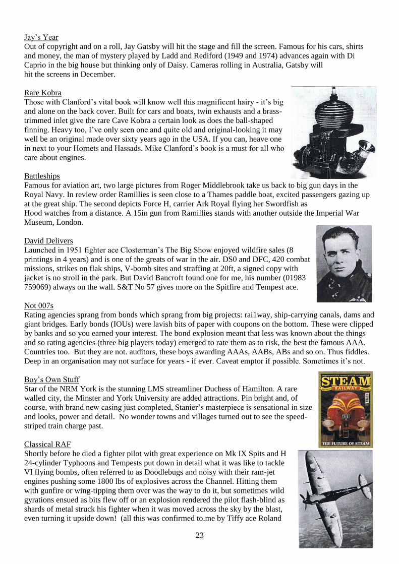
Best Bond?
In the Bahamas and waiting for his rnaster, Fido provides scale in this shot of the Vulcan used in
Thunderball (1965). Highjacking happens and along with the underwater fight and Largo’s Disco Volante,
the 007 franchise was really motoring. So big in fact that Thunderball
premiered at two cinemas in London (Row D at the London Pavilion costing
£26). A staggering 75 million saw the movie on release. A laugh was raised
on a Vulcan Squadron when a crew member walks back from the controls. In
a Vulcan you can’t do that. Fifty years ago the Bahamas was an unreachable
paradise for most, the preserve of rich men with all the trimmings and that’s
what made Thunderball great. Tom Jones sang the intro and John. Barry’s
music carried it along.
Fast Lady
A fine Brooklands shot of Kay Petre highlights the big steering wheel with
its could-be dangerous wire spokes. In a shunt, rim pushed forward, the
spear-like spokes could spring from the hub, enter arms, hands or chest,
even the driver’s neck or face. Outlawed in time, away from the race tracks
this classic wheel with its several spokes is still the bee’s knees along with
polished wood, thick carpet and leather and rows of proper instruments. As
here, the egg-shaped Merowitz goggles were worn by flyers too and could
be ground to correct sight defects. Wire mesh at the sides keeps the glass
free of condensation.
Box Vital
An age ago we junked the box and got on with building the model or bolting our new engine to the test
bench. Ted’s arrival a while ago with many kits and rolls of plans set me thinking one evening at Raynes
Park MAC. I guess the first box I saved held the Veron FWI90 control line kit. Stout and with magnificent
artwork, the rack or thumbscrews at least should have been my punishment had I discarded it. Boxes look
great alongside a built, model, as I’d see now and then at Old Warden. Chaps in the worldwide Hornby club
(HRCA) offer repro boxes for engines and stock, really the only way to care for an item outside a glass case.
Floppy boxes are ghastly, never closing properly,
strips of cardboard within one way out. Thankfully outfits like Rivers Knew what men wanted and delivered
Streaks and Arrows in Garth-strength containers studded with eight iron staples and wrapped in red, black
and white, the item dominant on the cover. And, of course, Merco and Oliver, Mills and ETA, Frog and ED,
even tin boxes from McCoy, did likewise - thank goodness!!
Jump To It!
When Pietersen slices a rocket you don’t stand still and field it! Best to aviate for a
few seconds as the ball screams away to a ‘four’ at least. Cricket on the big screen
now and then some may remember the farmer (Alan Bates) crack the ball all over
the field in The go-Between. (1970) until he is caught by his schoolboy Mercury
(Domonic Guard).
Green Shoots
First in Ohio in, 1980, I soon realised that there was or had been a strong German presence there. In their
covered wagons and pushing West an age before, the great Ohio River and the
mountains reminded the settlers of the Rhine and the mountains back home. Some went
on, others joined the Gold Rush, but many put down roots, built a railway and traded
with Chicago and Washington and sent goods north to the lakes as big as inland seas.
Young lads Proctor and Gamble borrowed money from banker Cunningham for a
floating soap idea and the rest is history. These days a world player in the soaps
business, P&G is the big boy in Cincinnati. It also saw the start of Vision Express and
Ohio is one of the famous Super Tuesday States.
23
Jay’s Year
Out of copyright and on a roll, Jay Gatsby will hit the stage and fill the screen. Famous for his cars, shirts
and money, the man of mystery played by Ladd and Rediford (1949 and 1974) advances again with Di
Caprio in the big house but thinking only of Daisy. Cameras rolling in Australia, Gatsby will
hit the screens in December.
Rare Kobra
Those with Clanford’s vital book will know well this magnificent hairy - it’s big
and alone on the back cover. Built for cars and boats, twin exhausts and a brass-
trimmed inlet give the rare Cave Kobra a certain look as does the ball-shaped
finning. Heavy too, I’ve only seen one and quite old and original-looking it may
well be an original made over sixty years ago in the USA. If you can, heave one
in next to your Hornets and Hassads. Mike Clanford’s book is a must for all who
care about engines.
Battleships
Famous for aviation art, two large pictures from Roger Middlebrook take us back to big gun days in the
Royal Navy. In review order Ramillies is seen close to a Thames paddle boat, excited passengers gazing up
at the great ship. The second depicts Force H, carrier Ark Royal flying her Swordfish as
Hood watches from a distance. A 15in gun from Ramillies stands with another outside the Imperial War
Museum, London.
David Delivers
Launched in 1951 fighter ace Closterman’s The Big Show enjoyed wildfire sales (8
printings in 4 years) and is one of the greats of war in the air. DS0 and DFC, 420 combat
missions, strikes on flak ships, V-bomb sites and straffing at 20ft, a signed copy with
jacket is no stroll in the park. But David Bancroft found one for me, his number (01983
759069) always on the wall. S&T No 57 gives more on the Spitfire and Tempest ace.
Not 007s
Rating agencies sprang from bonds which sprang from big projects: rai1way, ship-carrying canals, dams and
giant bridges. Early bonds (IOUs) were lavish bits of paper with coupons on the bottom. These were clipped
by banks and so you earned your interest. The bond explosion meant that less was known about the things
and so rating agencies (three big players today) emerged to rate them as to risk, the best the famous AAA.
Countries too. But they are not. auditors, these boys awarding AAAs, AABs, ABs and so on. Thus fiddles.
Deep in an organisation may not surface for years - if ever. Caveat emptor if possible. Sometimes it’s not.
Boy’s Own Stuff
Star of the NRM York is the stunning LMS streamliner Duchess of Hamilton. A rare
walled city, the Minster and York University are added attractions. Pin bright and, of
course, with brand new casing just completed, Stanier’s masterpiece is sensational in size
and looks, power and detail. No wonder towns and villages turned out to see the speed-
striped train charge past.
Classical RAF
Shortly before he died a fighter pilot with great experience on Mk IX Spits and H
24-cylinder Typhoons and Tempests put down in detail what it was like to tackle
VI flying bombs, often referred to as Doodlebugs and noisy with their ram-jet
engines pushing some 1800 lbs of explosives across the Channel. Hitting them
with gunfire or wing-tipping them over was the way to do it, but sometimes wild
gyrations ensued as bits flew off or an explosion rendered the pilot flash-blind as
shards of metal struck his fighter when it was moved across the sky by the blast,
even turning it upside down! (all this was confirmed to.me by Tìffy ace Roland
24
Beamont) But the arrival of the stunning V2, silent until impact, genesis of the 1969 Moon landing and
Japanese racing two-strokes, put the fighter bays out of business. So advanced in fact that the first V2 strikes
were put down to domestic gas explosions! Sqd Ldr Joseph Berry DFC of 501 Squadron sent down sixty
VIs and was the above expert before he died in October 1944 just 24. Formed in 1929 flying the DH9a,
501’s badge was a boar’s head and its motto Fear Nothing.
Great War Scout
Sopwith at Kingston cranked out famous fighters to tackle the enemy over the Western Front, their rotary
engines letting them spin on a sixpence. But one that was quite unlike the Camels and Pups, Triplanes and
Snipes was the V8 powered, 4 gun Dolphin, upper wings staggered back to improve forward view for the
pilot - who sat up high anyway. Now fully restored, a Dolphin is on show at Hendon. Plans and pictures are
ok for the Scale fiend, but the real thing close up really gets you in the mood. Nearest Tube is Colindale on
the Northern Line. Delight in the Dolphin and thank Hendon for yet another great achievement. Late from
Kingston was the ground attack Salamander with several guns (even7 tried) and more than 300lbs of
armour.
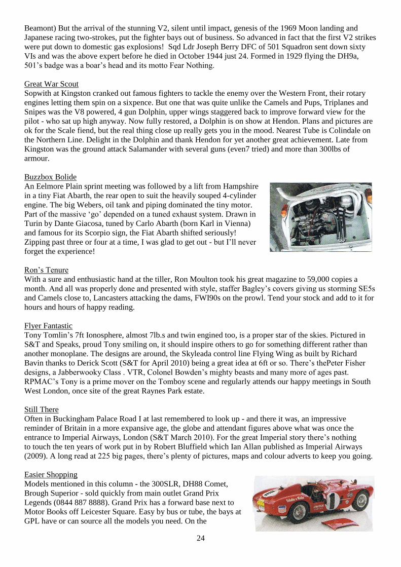
Buzzbox Bolide
An Eelmore Plain sprint meeting was followed by a lift from Hampshire
in a tiny Fiat Abarth, the rear open to suit the heavily souped 4-cylinder
engine. The big Webers, oil tank and piping dominated the tiny motor.
Part of the massive ‘go’ depended on a tuned exhaust system. Drawn in
Turin by Dante Giacosa, tuned by Carlo Abarth (born Karl in Vienna)
and famous for its Scorpio sign, the Fiat Abarth shifted seriously!
Zipping past three or four at a time, I was glad to get out - but I’ll never
forget the experience!
Ron’s Tenure
With a sure and enthusiastic hand at the tiller, Ron Moulton took his great magazine to 59,000 copies a
month. And all was properly done and presented with style, staffer Bagley’s covers giving us storming SE5s
and Camels close to, Lancasters attacking the dams, FWI90s on the prowl. Tend your stock and add to it for
hours and hours of happy reading.
Flyer Fantastic
Tony Tomlin’s 7ft Ionosphere, almost 7lb.s and twin engined too, is a proper star of the skies. Pictured in
S&T and Speaks, proud Tony smiling on, it should inspire others to go for something different rather than
another monoplane. The designs are around, the Skyleada control line Flying Wing as built by Richard
Bavin thanks to Derick Scott (S&T for April 2010) being a great idea at 6ft or so. There’s thePeter Fisher
designs, a Jabberwooky Class . VTR, Colonel Bowden’s mighty beasts and many more of ages past.
RPMAC’s Tony is a prime mover on the Tomboy scene and regularly attends our happy meetings in South
West London, once site of the great Raynes Park estate.
Still There
Often in Buckingham Palace Road I at last remembered to look up - and there it was, an impressive
reminder of Britain in a more expansive age, the globe and attendant figures above what was once the
entrance to Imperial Airways, London (S&T March 2010). For the great Imperial story there’s nothing
to touch the ten years of work put in by Robert Bluffield which Ian Allan published as Imperial Airways
(2009). A long read at 225 big pages, there’s plenty of pictures, maps and colour adverts to keep you going.
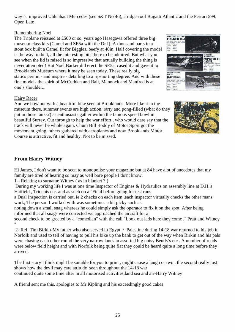
Easier Shopping
Models mentioned in this column - the 300SLR, DH88 Comet,
Brough Superior - sold quickly from main outlet Grand Prix
Legends (0844 887 8888). Grand Prix has a forward base next to
Motor Books off Leicester Square. Easy by bus or tube, the bays at
GPL have or can source all the models you need. On the
25
way is improved Uhlenhaut Mercedes (see S&T No 46), a ridge-roof Bugatti Atlantic and the Ferrari 599.
Open Late
Remembering Noel
The Triplane reissued at £500 or so, years ago Hasegawa offered three big
museum class kits (Camel and SE5a with the Dr I). A thousand parts in a
stout box built a Camel fit for Biggles, beefy at 40in. Half covering the model
is the way to do it, all the interesting bits there to be admired. But what you
see when the lid is raised is so impressive that actually building the thing is
never attempted! But Noel Barker did erect the SE5a, cased it and gave it to
Brooklands Museum where it may be seen today. These really big
statics permit - and inspire - detailing to a ripsnorting degree. And with these
fine models the spirit of McCudden and Ball, Mannock and Manfred is at
one’s shoulder...
Hairy Racer
And we bow out with a beautiful bike seen at Brooklands. More like it in the
museum there, summer events are high action, rarty and pong-filled (what do they
put in those tanks?) as enthusiasts gather within the famous speed bowl in
beautiful Surrey. Cut through to help the war effort., who would dare say that the
track will never be whole again. Chum Bill Boddy of Motor Sport got the
movement going, others gathered with aeroplanes and now Brooklands Motor
Course is attractive, fit and healthy. Not to be missed.
From Harry Witney
Hi James, I don't want to be seen to monopolise your magazine but at 84 have alot of anecdotes that my
family are tired of hearing so may as well bore people I do'nt know.
1-- Relating to surname Witney ( as in blanket ? )
During my working life I was at one time Inspector of Engines & Hydraulics on assembly line at D.H.'s
Hatfield , Tridents etc. and as such on a "Final before going for test runs
a Dual Inspection is carried out, ie 2 checks on each item ,each inspector virtually checks the other mans
work, The person I worked with was sometimes a bit picky such as
noting down a small snag whereas he could simply ask the operator to fix it on the spot. After being
informed that all snags were corrected we approached the aircraft for a
second check to be greeted by a "comedian" with the call "Look out lads here they come ," Pratt and Witney
"
2- Ref. Tim Birkin-My father who also served in Egypt / Palestine during 14-18 war returned to his job in
Norfolk and used to tell of having to pull his bike up the bank to get out of the way when Birkin and his pals
were chasing each other round the very narrow lanes in assorted big noisy Bently's etc . A number of roads
were below field height and with Norfolk being quite flat they could be heard quite a long time before they
arrived.
The first story I think might be suitable for you to print , might cause a laugh or two , the second really just
shows how the devil may care attitude seen throughout the 14-18 war
continued quite some time after in all motorised activities,land sea and air-Harry Witney
A friend sent me this, apologies to Mr Kipling and his exceedingly good cakes
26
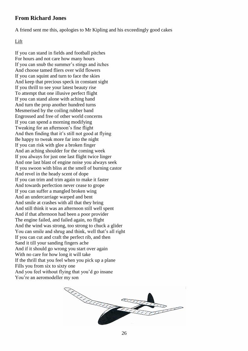
From Richard Jones
A friend sent me this, apologies to Mr Kipling and his exceedingly good cakes
Lift
If you can stand in fields and football pitches
For hours and not care how many hours
If you can snub the summer’s stings and itches
And choose tamed fliers over wild flowers
If you can squint and turn to face the skies
And keep that precious speck in constant sight
If you thrill to see your latest beauty rise
To attempt that one illusive perfect flight
If you can stand alone with aching hand
And turn the prop another hundred turns
Mesmerised by the coiling rubber band
Engrossed and free of other world concerns
If you can spend a morning modifying
Tweaking for an afternoon’s fine flight
And then finding that it’s still not good at flying
Be happy to tweak more far into the night
If you can risk with glee a broken finger
And an aching shoulder for the coming week
If you always for just one last flight twice linger
And one last blast of engine noise you always seek
If you swoon with bliss at the smell of burning castor
And revel in the heady scent of dope
If you can trim and trim again to make it faster
And towards perfection never cease to grope
If you can suffer a mangled broken wing
And an undercarriage warped and bent
And smile at crashes with all that they bring
And still think it was an afternoon still well spent
And if that afternoon had been a poor provider
The engine failed, and failed again, no flight
And the wind was strong, too strong to chuck a glider
You can smile and shrug and think, well that’s all right
If you can cut and craft the perfect rib, and then
Sand it till your sanding fingers ache
And if it should go wrong you start over again
With no care for how long it will take
If the thrill that you feel when you pick up a plane
Fills you from six to sixty one
And you feel without flying that you’d go insane
You’re an aeromodeller my son
27
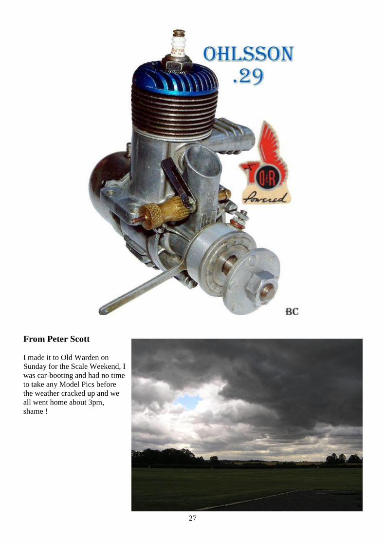
From Peter Scott
I made it to Old Warden on
Sunday for the Scale Weekend, I
was car-booting and had no time
to take any Model Pics before
the weather cracked up and we
all went home about 3pm,
shame !
28
29
30
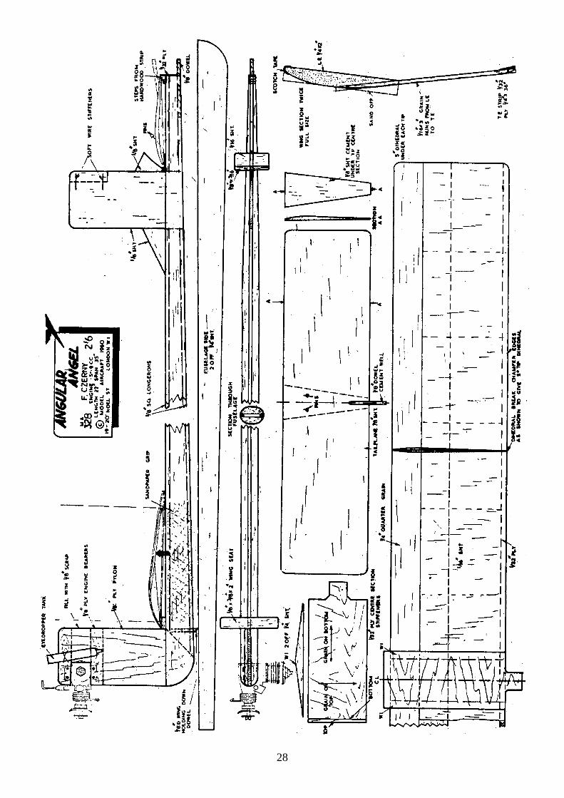
Ideal for beginners—two models that are simple, tough and really fly. Designed especially for novices
by noted Austrian modeller FRANZ CZERNY From Model Aircraft May 1960
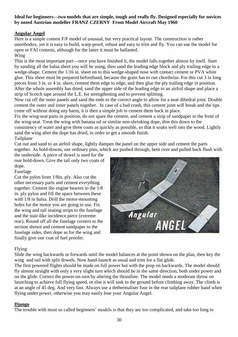
Angular Angel
Here is a simple contest F/F model of unusual, but very practical layout. The construction is rather
unorthodox, yet it is easy to build, warp-proof, robust and easy to trim and fly. You can use the model for
open or FAI contests, although for the latter it must be ballasted.
Wing
This is the most important part—once you have finished it, the model falls together almost by itself. Start
by sanding all the balsa sheet you will be using, then sand the leading edge block and ply trailing edge to a
wedge-shape. Cement the 1/16 in. sheet on to this wedge-shaped nose with contact cement or PVA white
glue. This sheet must be prepared beforehand, because the grain has to run chordwise. For this cut 3 in long
pieces from 3 in. or 4 in. sheet, cement them edge to edge, and then glue the ply trailing edge in position.
After the whole assembly has dried, sand the upper side of the leading edge to an airfoil shape and place a
strip of Scotch tape around the L.E. for strengthening and to prevent splitting.
Now cut off the outer panels and sand the ends to the correct angle to allow for a neat dihedral joint. Double
cement the outer and inner panels together. In case of a bad crash, this cement joint will break and the tips
come off without doing any harm, it is then a simple job to cement them back in place.
Fix the wing-seat parts in position, do not spare the cement, and cement a strip of sandpaper to the front of
the wing-seat. Treat the wing with banana oil or similar non-shrinking dope, thin this down to the
consistency of water and give three coats as quickly as possible, so that it soaks well into the wood. Lightly
sand the wing after the dope has dried, in order to get a smooth finish.
Tailplane
Cut out and sand to an airfoil shape, lightly dampen the panel on the upper side and cement the parts
together. As hold-downs, use ordinary pins, which are pushed through, bent over and pulled back flush with
the underside. A piece of dowel is used for the
rear hold-down. Give the tail only two coats of
dope.
Fuselage
Cut the pylon from 1/8in. ply. Also cut the
other necessary parts and cement everything
together. Cement the engine bearers to the 1/8
in. ply pylon and fill the space between these
with 1/8 in balsa. Drill the motor-mounting
holes for the motor you are going to use. Fix
the wing and tail seating strips to the fuselage
and the stair-like incidence piece (extreme
rear). Round off all the fuselage corners to the
section shown and cement sandpaper to the
fuselage sides, then dope as for the wing and
finally give one coat of fuel proofer.
Flying
Slide the wing backwards or forwards until the model balances at the point shown on the plan, then key the
wing and tail with split dowels. Now hand-launch as usual and trim for a flat glide.
The first powered flights should be made on full power but with the prop on backwards. The model should
fly almost straight with only a very slight turn which should be in the same direction, both under power and
on the glide. Correct the power-on turn by altering the thrustline. The model needs a moderate throw on
launching to achieve full flying speed, or else it will sink to the ground before climbing away. The climb is
at an angle of 45 deg. And very fast. Always use a dethermaliser fuse in the rear tailplane rubber band when
flying under power, otherwise you may easily lose your Angular Angel.
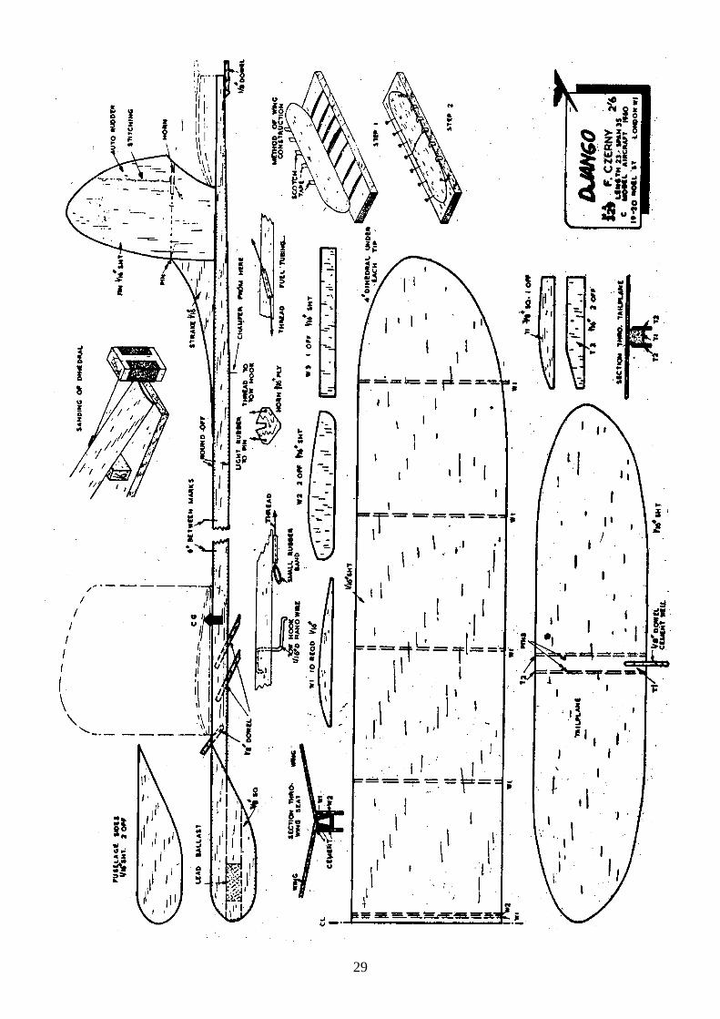
Django
The trouble with most so called beginners’ models is that they are too complicated, and take too long to
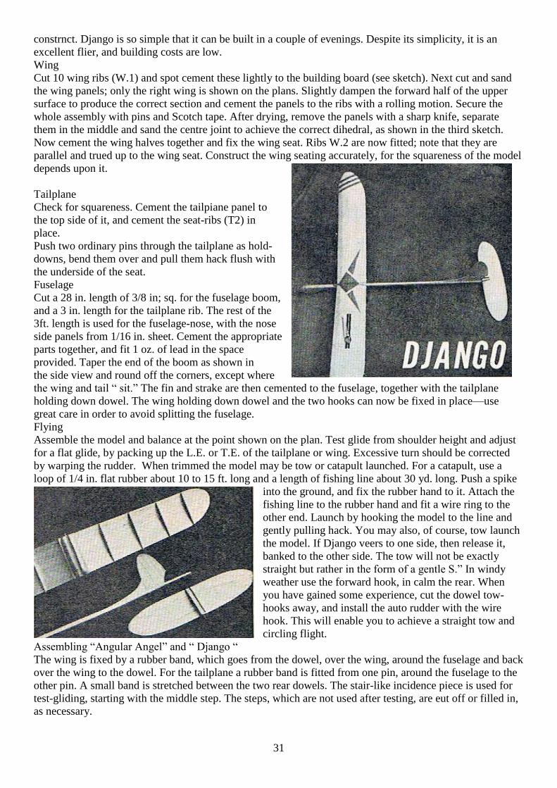
31
constrnct. Django is so simple that it can be built in a couple of evenings. Despite its simplicity, it is an
excellent flier, and building costs are low.
Wing
Cut 10 wing ribs (W.1) and spot cement these lightly to the building board (see sketch). Next cut and sand
the wing panels; only the right wing is shown on the plans. Slightly dampen the forward half of the upper
surface to produce the correct section and cement the panels to the ribs with a rolling motion. Secure the
whole assembly with pins and Scotch tape. After drying, remove the panels with a sharp knife, separate
them in the middle and sand the centre joint to achieve the correct dihedral, as shown in the third sketch.
Now cement the wing halves together and fix the wing seat. Ribs W.2 are now fitted; note that they are
parallel and trued up to the wing seat. Construct the wing seating accurately, for the squareness of the model
depends upon it.
Tailplane
Check for squareness. Cement the tailpiane panel to
the top side of it, and cement the seat-ribs (T2) in
place.
Push two ordinary pins through the tailplane as hold-
downs, bend them over and pull them hack flush with
the underside of the seat.
Fuselage
Cut a 28 in. length of 3/8 in; sq. for the fuselage boom,
and a 3 in. length for the tailplane rib. The rest of the
3ft. length is used for the fuselage-nose, with the nose
side panels from 1/16 in. sheet. Cement the appropriate
parts together, and fit 1 oz. of lead in the space
provided. Taper the end of the boom as shown in
the side view and round off the corners, except where
the wing and tail “ sit.” The fin and strake are then cemented to the fuselage, together with the tailplane
holding down dowel. The wing holding down dowel and the two hooks can now be fixed in place—use
great care in order to avoid splitting the fuselage.
Flying
Assemble the model and balance at the point shown on the plan. Test glide from shoulder height and adjust
for a flat glide, by packing up the L.E. or T.E. of the tailplane or wing. Excessive turn should be corrected
by warping the rudder. When trimmed the model may be tow or catapult launched. For a catapult, use a
loop of 1/4 in. flat rubber about 10 to 15 ft. long and a length of fishing line about 30 yd. long. Push a spike
into the ground, and fix the rubber hand to it. Attach the
fishing line to the rubber hand and fit a wire ring to the
other end. Launch by hooking the model to the line and
gently pulling hack. You may also, of course, tow launch
the model. If Django veers to one side, then release it,
banked to the other side. The tow will not be exactly
straight but rather in the form of a gentle S.” In windy
weather use the forward hook, in calm the rear. When
you have gained some experience, cut the dowel tow-
hooks away, and install the auto rudder with the wire
hook. This will enable you to achieve a straight tow and
circling flight.
Assembling “Angular Angel” and “ Django “
The wing is fixed by a rubber band, which goes from the dowel, over the wing, around the fuselage and back
over the wing to the dowel. For the tailplane a rubber band is fitted from one pin, around the fuselage to the
other pin. A small band is stretched between the two rear dowels. The stair-like incidence piece is used for
test-gliding, starting with the middle step. The steps, which are not used after testing, are eut off or filled in,
as necessary.
32
33
Mike Fairgray [email protected]
I have been sent your latest publication by a member of my club (Auckland Model Aero Club) and would
like to be placed on your email list.
In response to your request for an article I am a member of the National Association (NZMAA) Control
Line & Free Flight Scale Special Interest Group.
We have recently held a F/F Scale day and I have attached a report as written by our Chairman and photos
which you may use if you find it interesting to your readers. I can continue to forward reports and photos of
other F/F scale meetings if you wish. Last year we held a postal competition for Earl Stahl models and this
year we are holding another postal comp for any scale models made from a published plan which opens up
all sorts of models from kits to mags from magazines such as Aeromodeller. The model must be made as
per the plan so to keep the details and finish simple and thus hope to encourage other modellers to have a go
at a scale model. In addition to this we have introduced into our National Competitions a a new comp for kit
scale I have attached a set of rules for your information.
As the photos puts me over my email size I will send them to you in a separate email.
Kit Scale Rules: Effective June 2012
Introduction:
Kit Scale will be run as an official event at the Nationals using the British Model Fliers Assoc (BMFA)
rules. The intent of kit scale is to offer an easy class to fliers who may not wish to build the developed and
detailed models required by existing Scale Competition Scale Rules for example. In essence, any small
scale model originally offered as a commercial kit qualifies. This brings in Keil Kraft, Veron, SIG, Peck,
Skyleader, Modelair, Airsail, and many others either currently in production or those old 50s and 60s
designs you have always wanted to build. The spirit of the class is that you build as close to the original plan
as possible. Deviations are penalised.
Rules
A. The maximum weight is150g (including motor).
B. There are no wingspan limitations.
C. The model may be powered by rubber, CO2 or electric.
D. Models may be built from kit parts or the builder’s own wood but the kit plan must be provided as
authentication.
E. The only modifications permitted (without marks penalty) from the original kit are those associated
with fitting an alternative power source, a replacement propeller (including for rubber) and wheels.
F. The minimum flight time is 10 seconds.
Documentation:
The minimum documentation required is the original (or photocopy) plan from which the model was built
and one photograph, drawing or painting (e.g. box art) of either the aircraft modelled or a similar aircraft
from the same era to authenticate the general colour scheme and markings.
Static Marking
A. Points will be awarded up to the maximum of 100 to reflect the quality of workmanship and
character of the models made up as follows.
B. Workmanship is scored up to 60%,
C. Authenticity of colour scheme and accuracy of Markings (if present) 20%
D. Overall character 20%.
Penalties for deviations from the plan:
Most models will have a coloured tissue finish with painted, printed, transfer or tissue markings.
• Fully painted models will not be excluded but will have 5 points deducted from their static score.
• 5 points will also be deducted for each significant deviation from the original design other than those
permitted above, e.g. increased dihedral, separate control surfaces where these are not shown on the plan etc.
34
Flying Points
10 points will be awarded for each of the following
A. Take-off (optional)
B. Initial climb
C. Descent and landing approach
D. Quality of Landing.
E. A maximum of 20 points in total will be awarded for Realism in fight (speed, ‘sit’, stability and
character).
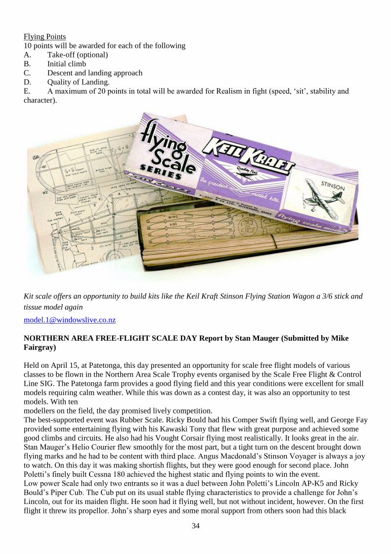
Kit scale offers an opportunity to build kits like the Keil Kraft Stinson Flying Station Wagon a 3/6 stick and
tissue model again
NORTHERN AREA FREE-FLIGHT SCALE DAY Report by Stan Mauger (Submitted by Mike
Fairgray)
Held on April 15, at Patetonga, this day presented an opportunity for scale free flight models of various
classes to be flown in the Northern Area Scale Trophy events organised by the Scale Free Flight & Control
Line SIG. The Patetonga farm provides a good flying field and this year conditions were excellent for small
models requiring calm weather. While this was down as a contest day, it was also an opportunity to test
models. With ten
modellers on the field, the day promised lively competition.
The best-supported event was Rubber Scale. Ricky Bould had his Comper Swift flying well, and George Fay
provided some entertaining flying with his Kawaski Tony that flew with great purpose and achieved some
good climbs and circuits. He also had his Vought Corsair flying most realistically. It looks great in the air.
Stan Mauger’s Helio Courier flew smoothly for the most part, but a tight turn on the descent brought down
flying marks and he had to be content with third place. Angus Macdonald’s Stinson Voyager is always a joy
to watch. On this day it was making shortish flights, but they were good enough for second place. John
Poletti’s finely built Cessna 180 achieved the highest static and flying points to win the event.
Low power Scale had only two entrants so it was a duel between John Poletti’s Lincoln AP-K5 and Ricky
Bould’s Piper Cub. The Cub put on its usual stable flying characteristics to provide a challenge for John’s
Lincoln, out for its maiden flight. He soon had it flying well, but not without incident, however. On the first
flight it threw its propellor. John’s sharp eyes and some moral support from others soon had this black
35
propellor found, and on the model again. With only a few marks between them in flying, it was static scores
that separated the final winners of this event. There were a number of starters in F4A Power Scale, but in the
end it became a contest between just two fliers. Paul Evans flew his Bristol Brownie. It seemed to need just
some tweaking of thrust-lines to get it flying more stably. It is a scale subject with lots of character. Don
Spray’s Heinkel was really gaining altitude in some tight circles. George Fay was unable to proceed with
further flights of his Douglas Dauntless after the engine bearer section came adrift in a heavy landing. It was
down to John Poletti with his beautifully built Vickers Venom and Stan Mauger who entered his spritely
Piper TriPacer. Stan achieved a good enough flight to gain some advantage, but there was only a small
points margin between the two models, both of which flew well. This contest day could not have been run
without the contribution of the judges. A big thank you to Paul Evans for judging rubber flying and Angus
Macdonald for looking after F4A Power flying and static judging. Thanks also to Keith Trillo and Mike
Fairgray for assisting with static judging of rubber scale. Mike also took some great photographs, some
of which accompany this report. Special thanks also to Peter Kowalski for the use of the farm again this
year. The superb weather conditions contributed to an enjoyable day’s flying and there was so much activity
that fliers found that there was no time to get out some models brought for the day. All of which made the
journey to the field well worth the effort.
Results
Static Flying Total
F4A Power scale
1. S. Mauger Piper Tri Pacer 786 410 1196
2. J. Poletti Vickers Venom 740 390 1130
Rubber scale
1. J. Poletti Cessna 180 866 455 1321
2. A. Macdonald Stinson Voyager 766 377 1143
3. S. Mauger Helio Courier 799 331 1130
4. G. Fay Kawasaki Tony 724 404 1128
5. R. Bould Comper Swift 556 387 943
Low Power scale
1. J. Poletti Lincoln AP-K5 777 434 1211
2. R. Bould Piper Cub 657 423 1080
All photos by Mike Fairgray
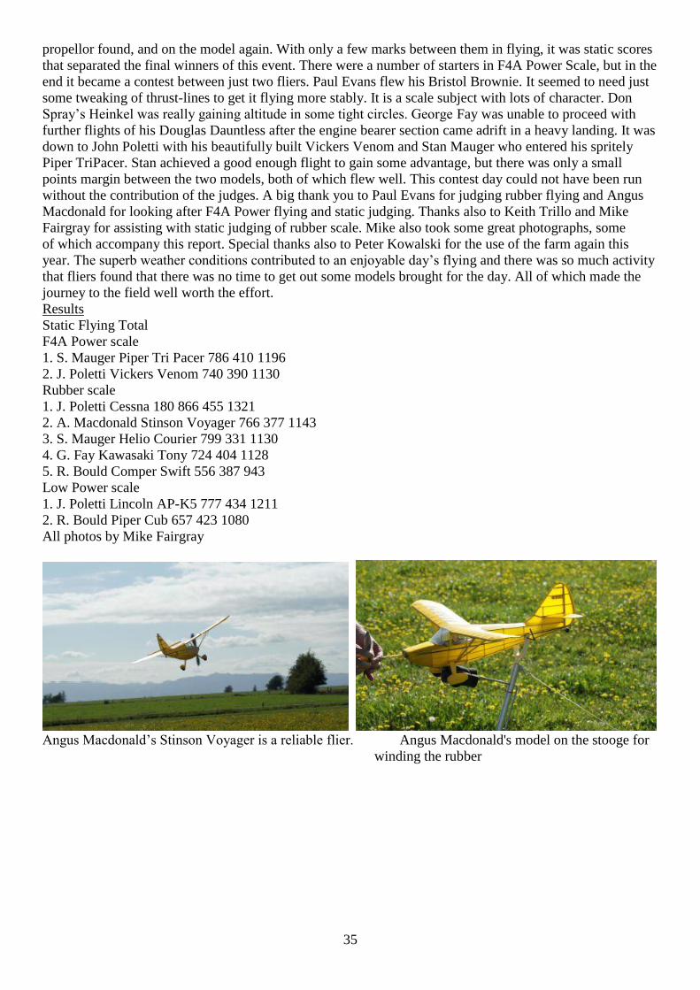
Angus Macdonald’s Stinson Voyager is a reliable flier. Angus Macdonald's model on the stooge for
winding the rubber
36
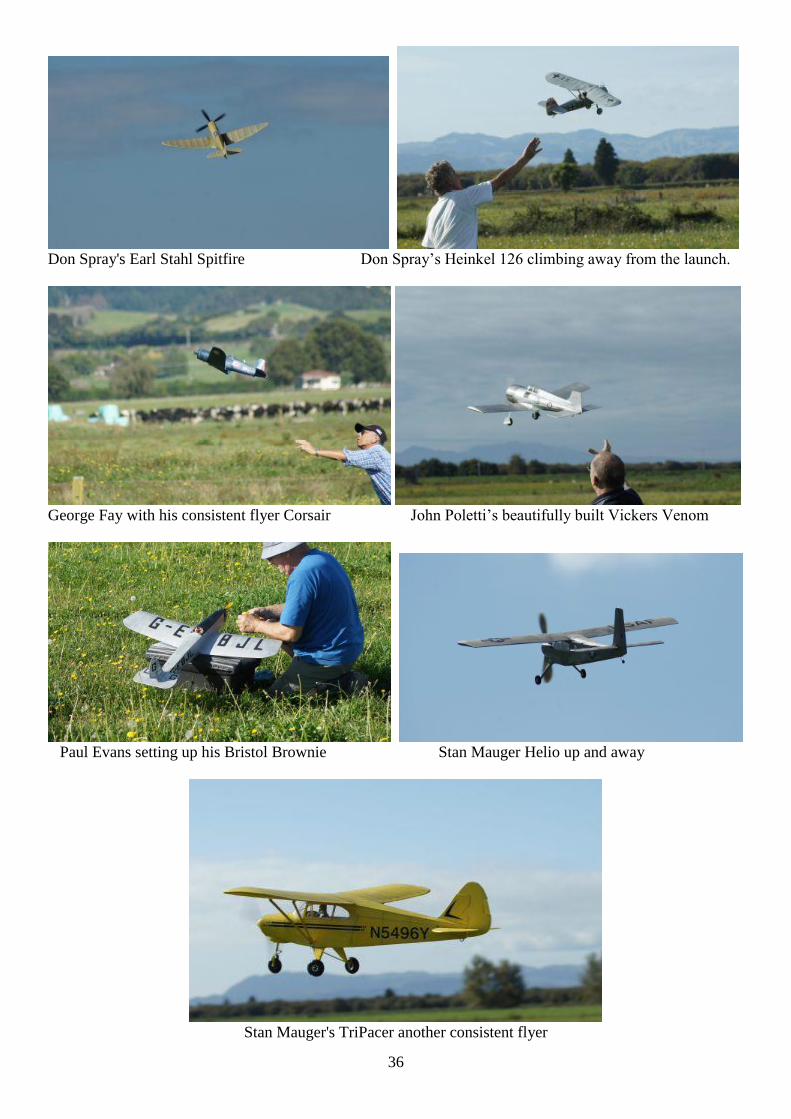
Don Spray's Earl Stahl Spitfire Don Spray’s Heinkel 126 climbing away from the launch.
George Fay with his consistent flyer Corsair John Poletti’s beautifully built Vickers Venom
Paul Evans setting up his Bristol Brownie Stan Mauger Helio up and away
Stan Mauger's TriPacer another consistent flyer
37
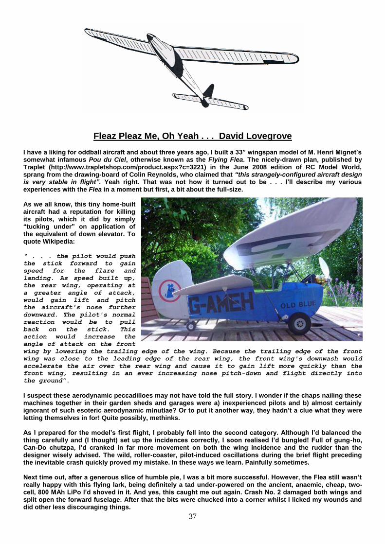
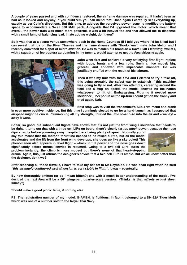
Fleaz Pleaz Me, Oh Yeah . . . David Lovegrove I have a liking for oddball aircraft and about three years ago, I built a 33” wingspan model of M. Henri Mignet’s somewhat infamous Pou du Ciel, otherwise known as the Flying Flea. The nicely-drawn plan, published by Traplet (http://www.trapletshop.com/product.aspx?c=3221) in the June 2008 edition of RC Model World, sprang from the drawing-board of Colin Reynolds, who claimed that “this strangely-configured aircraft design is very stable in flight”. Yeah right. That was not how it turned out to be . . . I’ll describe my various experiences with the Flea in a moment but first, a bit about the full-size. As we all know, this tiny home-built aircraft had a reputation for killing its pilots, which it did by simply “tucking under” on application of the equivalent of down elevator. To quote Wikipedia: “ . . . the pilot would push
the stick forward to gain
speed for the flare and
landing. As speed built up,
the rear wing, operating at
a greater angle of attack,
would gain lift and pitch
the aircraft's nose further
downward. The pilot's normal
reaction would be to pull
back on the stick. This
action would increase the
angle of attack on the front
wing by lowering the trailing edge of the wing. Because the trailing edge of the front
wing was close to the leading edge of the rear wing, the front wing's downwash would
accelerate the air over the rear wing and cause it to gain lift more quickly than the
front wing, resulting in an ever increasing nose pitch-down and flight directly into
the ground”.
I suspect these aerodynamic peccadilloes may not have told the full story. I wonder if the chaps nailing these machines together in their garden sheds and garages were a) inexperienced pilots and b) almost certainly ignorant of such esoteric aerodynamic minutiae? Or to put it another way, they hadn’t a clue what they were letting themselves in for! Quite possibly, methinks. As I prepared for the model’s first flight, I probably fell into the second category. Although I’d balanced the thing carefully and (I thought) set up the incidences correctly, I soon realised I’d bungled! Full of gung-ho, Can-Do chutzpa, I’d cranked in far more movement on both the wing incidence and the rudder than the designer wisely advised. The wild, roller-coaster, pilot-induced oscillations during the brief flight preceding the inevitable crash quickly proved my mistake. In these ways we learn. Painfully sometimes. Next time out, after a generous slice of humble pie, I was a bit more successful. However, the Flea still wasn’t really happy with this flying lark, being definitely a tad under-powered on the ancient, anaemic, cheap, two-cell, 800 MAh LiPo I’d shoved in it. And yes, this caught me out again. Crash No. 2 damaged both wings and split open the forward fuselage. After that the bits were chucked into a corner whilst I licked my wounds and did other less discouraging things.
38
A couple of years passed and with confidence restored, the airframe damage was repaired. It hadn’t been as bad as it looked and anyway, if you build ‘em you can mend ‘em! Once again I carefully set everything up, exactly as per Colin’s directions. But this time, to address the perceived power issue I’d modified the battery space to accommodate a 3-cell 800 MAh pack. Alongside that I’d upgraded the motor, which meant that overall, the power train was much more powerful. It was a bit heavier too and that allowed me to dispense with a small lump of balancing lead. I hate adding weight, don’t you? So it was that at a secret venue somewhere posh in the Home Counties (if I told you where I’d be killed but I can reveal that it’s on the River Thames and the name rhymes with “Hook- ‘em”) mate John Mellor and I recently convened for a spot of micro aviation. He was to maiden his brand-new Dave Platt Fleetwing, whilst I, with a squadron of lepidoptera aerobatting in my tummy, would attempt to get the Flea airborne again.
John went first and achieved a very satisfying first flight, replete with loops, bunts and a few rolls. Such a nice model; big, graceful and endowed with impeccable manners. He was justifiably chuffed with the result of his labours. Then it was my turn with the Flea and I elected to try a take-off, this being arguably the safest way to establish if this machine was going to fly or not. After two attempts, careering around the field like a frog on speed, the model showed no inclination whatsoever to lift off. Embarassing. Figuring it needed more incidence, I beeped-in all the up-trim I could get on the tranny and tried again. Nah. Next stop was to visit the transmitter’s Sub-Trim menu and crank
in even more positive incidence. But this time I cunningly elected to go for a hand-launch, as I suspected that airspeed might be crucial. Summoning all my strength, I hurled the little so-and-so into the air and – wahay! – away it went. So far, so good, but subsequent flights have shown that it’s not just the front wing’s incidence that needs to be right. It turns out that with a three-cell LiPo on board, there’s clearly far too much power, because the nose dips sharply before powering away, despite there being plenty of speed. Normally you’d say this meant that the motor’s thrustline needed to be raised a little, but as the model accelerates and the lift from the front wing develops, she goes up like a skyrocket! This phenomenon also appears in level flight – whack in full power and the nose goes down significantly before normal service is resumed. Going to a two-cell LiPo cures the problem instantly; the climb is more modest but there’s none of that heart-stopping drama. Again, this just affirms the designer’s advice that a two-cell LiPo is ample. But we all know better than the designer, don’t we? After resolving all those travails, I have to take my hat off to Mr Reynolds. He was dead right when he said “this strangely-configured airdraft design is very stable in flight”. It was – eventually. By now thoroughly smitten (or do I mean bitten?) and with a much better understanding of the model, I’ve decided the next Flea will be a 66” wingspan, quarter-scale version. (Thinks: is that naïvety or just sheer lunacy?) Should make a good picnic table, if nothing else. PS: The registration number of my model, G-AMEH, is fictitious. In fact it belonged to a DH-82A Tiger Moth which was one of a number sold to the Royal Thai Navy.
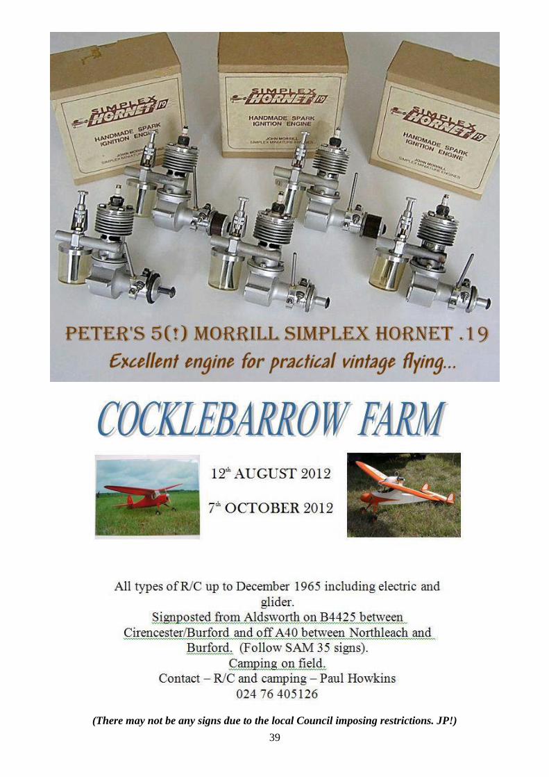
39
(There may not be any signs due to the local Council imposing restrictions. JP!)
40
Vic Smeed Tribute Week 2012 As announced in the December 2011 SAM 35 Speaks, we propose that the week Sept 2nd – 9th should be dedicated to celebrating Vic Smeed’s designs on a world-wide basis. Please send your photos and anecdotes of/about flights made during this period to Power Struggle columnist Mike Parker ([email protected]). In addition there will be special events at the Vic Smeed Memorial Day during the OW ModelAir Festival of Flight weekend (Sept8th/9th). Please bring along your Vic Smeed models for display on the Sunday, when a Concours award will be presented. The Vic Smeed Memorial Trophy Competition will also be held on the Sunday. Doug Wass has contributed a superb Trophy for this event and has arranged sponsorship to provide prizes, which will include a kit of Vic’s “Chatterbox”, kindly donated by Falcon Models. The competition will be a spot landing event for 2.4 GHz R/C assisted FF models according to the following rules: 1 Models must be an acknowledged Vic Smeed design. (Allows for unpublished designs e.g. Metre Maid) 2 Scaling up or down is permitted provided that the maximum engine size is 0.87cc/.049 cu.in. 3 Builder of the model rule applies. 4 Models and fliers shall comply with site rules currently in force. 5 Models shall have rudder only radio assistance: if the model normally has elevator/engine control it must be rendered inoperative. N.B. 2.4 GHz only 6 Minimum engine run must be 45 seconds. In windy conditions the competition director has discretion to reduce this to an appropriate time down to a minimum of 30 seconds. 7 Placing in the competition is based on models coming to rest nearest to a designated spot on the field. 8 In the event of a tie for first place there will be a fly off. 9 The Contest Director’s decision will be final! We hope that this new event will be well supported – there are lots of Tomboy 3 flyers out there, so bring yours along, disable the elevator and join in the fun!
POST S&T
On Sunday 12 August Wimborne MAC will be holding an RC Classic 1955 – 75 day.
The site is at Cashmoor which is situated on the A354 between Blandford Forum and Salisbury.
The entrance gate is located at N 50° 55’ 27.23 W °02 01’ 50.34
Contact myself James Parry [email protected] for more details
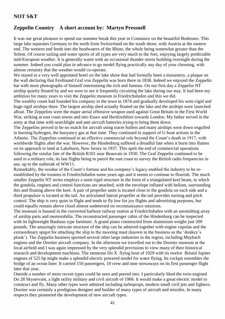
41
NOT S&T
Zeppelin Country A short account by: Martyn Pressnell
It was our great pleasure to spend our summer break this year in Constance on the beautiful Bodensee. This
large lake separates Germany to the north from Switzerland on the south shore, with Austria at the eastern
end. The western end feeds into the headwaters of the Rhine, the whole being somewhat greater than the
Solent. Of course sailing and water sports of all types are very much to the fore, enjoying largely predictable
mid-European weather. It is generally warm with an occasional thunder storm building overnight during the
summer. Indeed you could plan in advance to go model flying practically any day of your choosing, with
almost certainty that the weather would co-operate.
We stayed in a very well appointed hotel on the lake shore that had formally been a monastery, a plaque on
the wall declaring that Ferdinand Graf von Zeppelin was born there in 1838. Indeed we enjoyed the Zeppelin
bar with more photographs of himself entertaining the rich and famous. On our first day a Zeppelin NT
airship quietly floated by and we were to see it frequently circuiting the lake during our stay. It had been my
ambition for many years to visit the Zeppelin museum in Friedrichshafen and this we did.
The wealthy count had founded his company in the town in 1874 and gradually developed his semi-rigid and
huge rigid airships there. The largest airship shed actually floated on the lake and the airships were launched
afloat. The Zeppelins were the major aerial offensive weapon used against Great Britain in the First World
War, striking at east coast towns and into Essex and Hertfordshire towards London. My father served in the
army at that time with searchlight and anti-aircraft batteries trying to bring them down.
The Zeppelins proved to be no match for aircraft using tracer bullets and many airships went down engulfed
in burning hydrogen, the buoyancy gas at that time. They continued in support of U-boat actions in the
Atlantic. The Zeppelins continued in an effective commercial role beyond the Count’s death in 1917, with
worldwide flights after the war. However, the Hindenburg suffered a dreadful fate when it burst into flames
on its approach to land at Lakehurst, New Jersey in 1937. This spelt the end of commercial operations
following the similar fate of the British R101 near Beauvais in 1930. The Graf Zeppelin continued to be
used in a military role, its last flights being to patrol the east coast to survey the British radio frequencies in
use, up to the outbreak of WW11.
Remarkably, the residue of the Count’s fortune and his company’s legacy enabled the industry to be re-
established by the trustees in Friedrichshafen some years ago and it seems to continue to flourish. The much
smaller Zeppelin NT series employs a semi-rigid structure in the form of a triangulated keel beam, to which
the gondola, engines and control functions are attached, with the envelope inflated with helium, surrounding
this and floating above the keel. A pair of propeller units is located close to the gondola on each side and a
third propulsor is located at the tail. An articulated lateral propeller at the tail provides turning and pitch
control. The ship is very quiet in flight and tends to fly low for joy flights and advertising purposes, but
could equally remain above cloud almost undetected on reconnaissance missions.
The museum is housed in the converted harbour railway station at Friedrichshafen with an astonishing array
of airship parts and memorabilia. The reconstructed passenger cabin of the Hindenburg can be inspected
with its lightweight Bauhaus type furniture. A grand piano constructed from aluminium weighs just 200
pounds. The amazingly intricate structure of the ship can be admired together with engine cupolas and the
extraordinary spigot for attaching the ship to the mooring mast (known in the business as the ‘donkey’s
plonk’). The Zeppelin business sporned several other large industries in the region, including Maybach
engines and the Dornier aircraft company. In the afternoon we travelled out to the Dornier museum at the
local airfield and I was again impressed by the very splendid provisions to view many of their historical
research and development machines. The immense Do X flying boat of 1929 with its twelve Bristol Jupiter
engines of 525 hp might make a splendid electric powered model for water flying. Its cockpit resembles the
bridge of an ocean liner. It carried 150 passengers, 10 crew and nine stowaways on its first passenger flight
later that year.
Outside a number of more recent types could be seen and peered into. I particularly liked the twin-engined
Do 28 Skyservant, a light utility military and civil aircraft of 1966. It would make a great electric model to
construct and fly. Many other types were admired including turboprops, modern small civil jets and fighters.
Dornier was certainly a prodigious designer and builder of many types of aircraft and missiles. In many
respects they pioneered the development of new aircraft types.
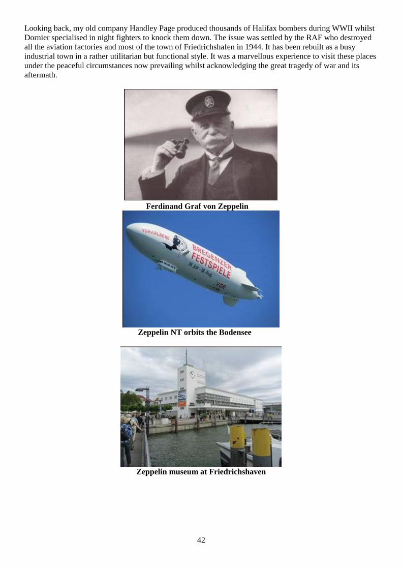
42
Looking back, my old company Handley Page produced thousands of Halifax bombers during WWII whilst
Dornier specialised in night fighters to knock them down. The issue was settled by the RAF who destroyed
all the aviation factories and most of the town of Friedrichshafen in 1944. It has been rebuilt as a busy
industrial town in a rather utilitarian but functional style. It was a marvellous experience to visit these places
under the peaceful circumstances now prevailing whilst acknowledging the great tragedy of war and its
aftermath.
Ferdinand Graf von Zeppelin
Zeppelin NT orbits the Bodensee
Zeppelin museum at Friedrichshaven
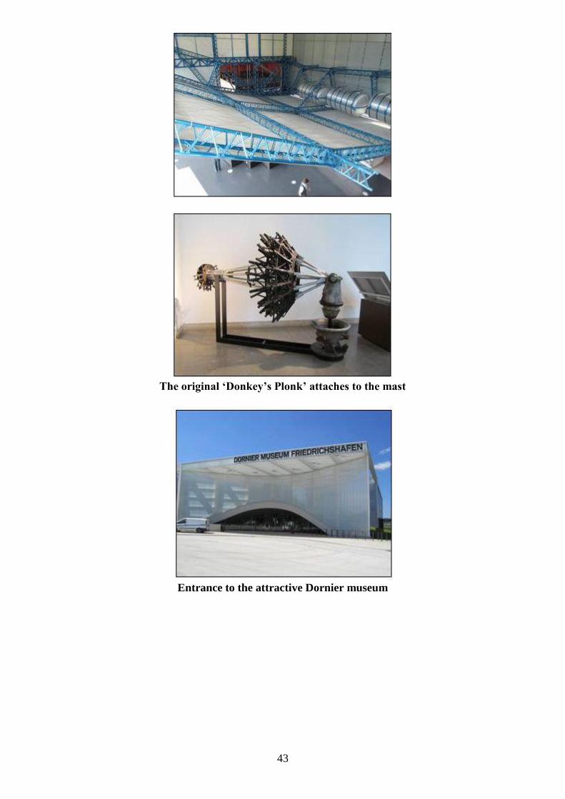
43
The original ‘Donkey’s Plonk’ attaches to the mast
Entrance to the attractive Dornier museum
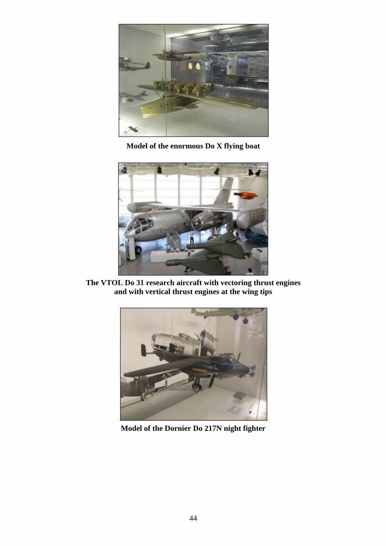
44
Model of the enormous Do X flying boat
The VTOL Do 31 research aircraft with vectoring thrust engines
and with vertical thrust engines at the wing tips
Model of the Dornier Do 217N night fighter
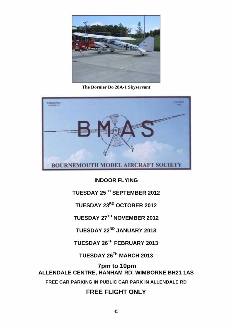
45
The Dornier Do 28A-1 Skyservant
INDOOR FLYING
TUESDAY 25TH SEPTEMBER 2012
TUESDAY 23RD OCTOBER 2012
TUESDAY 27TH NOVEMBER 2012
TUESDAY 22ND JANUARY 2013
TUESDAY 26TH FEBRUARY 2013
TUESDAY 26TH MARCH 2013
7pm to 10pm ALLENDALE CENTRE, HANHAM RD. WIMBORNE BH21 1AS
FREE CAR PARKING IN PUBLIC CAR PARK IN ALLENDALE RD
FREE FLIGHT ONLY
46
COMPETITIONS incl GYMINNIE CRICKET LEAGUE
ALL FLYERS MUST HAVE BMFA INSURANCE
FLITEHOOK NORMALLY IN ATTENDANCE
Adult Flyers £4 Accompanied Juniors & Spectators £1.50
CONTACTS:JOHN TAYLOR TEL.No 01202 511502 ROY TILLER e-mail [email protected]