Embed Size (px)
Citation preview
Stereoscopic Matchmoving in 3DE4
SDV - publiccompiled on 15.01.2010
Version 1: 2009-08-10
Version 2: 2009-08-12, Rotation policy
Version 3: 2009-08-14, Zoom
Version 4: 2009-08-18, Interocular
Version 5: 2009-09-15, English and completely restructured
Version 6: 2009-10-02, Object Point Group, Depth Shift
Version 7: 2010-01-12, Semi-transparent mirror
Contents
1 Introduction2 Definitions
2.1 The ideal Stereo Rig2.1.1 Lens distortion
2.2 A realistic Stereo Rig3 Stereoscopy in 3DE4
3.1 Basic Setup3.1.1 Classification of 3DE4-projects3.1.2 Single lens vs. separate lenses
3.2 Parameters and Policies3.2.1 Interocular
3.2.1.1 Static adjust vs. Static calculated3.2.1.2 Sign convention
3.2.2 Vertical Shift3.2.3 Depth Shift3.2.4 Rotation Policy3.2.5 Zoom Policy3.2.6 Parameter Adjustment
3.2.6.1 Brute Force vs. Adaptive Parameter Adjustment3.3 One Point Group (CamPG)3.4 One Point Group (ObjPG)3.5 More than one Point Group (CamPG + ObjPG)
3.5.1 Trouble-shooting: Reducing the project3.5.2 The Synchronicity Relation (SyncRel)
3.6 Special Modes3.6.1 Stereoscopy on Nodal Shots, no Survey
3.6.1.1 Parameter Adjustment3.6.1.2 Current state of development
3.7 Stereoscopy in relation to other functions of 3DE43.7.1 Interpolation
1
3.8 Current State of Development3.8.1 Known Bugs3.8.2 Unknown Bugs
A MathematicsA.1 Interocular, vertical shift, depth shiftA.2 Parallaxe and Convergence Point
B Semi-transparent mirrorB.1 RefractionB.2 ModellingB.3 ExamplesB.4 LimitsB.5 Primary camera looking up
1 IntroductionThe purpose of this document is to fix some definitions and terminology we use in 3DE4 and togive an overview how stereoscopic projects can be done. This document is not meant to be atutorial, but to provide some additional information which usually is not part of a tutorial. It isaddressed to experienced users. The document refers to 3DE4 release 1 beta 6.
2 DefinitionsIn the following we will juxtapose the ideal stereo rig and it's realistic counterpart. A realisticstereo has (usually unintentionally) more degrees of freedom than the ideal one, and 3DE4 shouldbe able to account for this. Some of the additional degrees of freedom are due to physical impact,others are a inherent to construction of the rig.
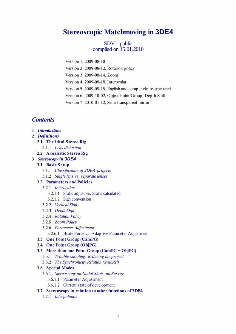
2.1 The ideal Stereo RigWe consider a stereo rig to be ideal when it is constructed in an exactely symmetric way. Theoptical axes of both rig intersect precisely in a point which is called convergence point. Theprojection centers of both camera have the same distance to the convergence point. The rightvectors of both cameras lie in within the stereoscopic plane. As a consequence the up-vectors areparallel. Interocular and parallaxe vary in a well-defined way during the shot and are smoothfunctions over time. When zoom lenses are used, the zoom factors of both cameras are equal ateach time.
2
2.1.1 Lens distortionLens distortion is basically not a draw back of the ideal stereo rig, as long as it is always the samefor both cameras (which in practice is not the case). When lens distortion depends on otherparameters like zoom (or even parallaxe), the dependency must be the same for both cameras.When this is granted, lens distortion can easily be compensated, and we still consider the rig asideal.
2.2 A realistic Stereo RigAccording to our experience which is based on reports from users, in a real scenario there can beundesired effects, which we will describe now. For any given time during the shot the followingcan occur:
The two cameras are not at the same height level (→ vertical shift)The optical axes do not intersect (i.e. they are skew. This affects the definition ofconvergence)The right vector of at least one of the cameras is not parallel to the stereoscopic plane (→rotation policy)The two cameras have different optical properties like focal length, lens distortion(→distinct lens objects in 3DE4)The two cameras are not at the same depth level (→ depth shift). This is an artefact ofasymmetric construction e.g. by means of mirrors.
Additionally, the following time-dependent effects can occur:
In case of zooming, the cameras have different zoom factors (→ zoom policy). Since bothcamera have their own zoom lenses, zoom factors will be equal only up to a certainprecision. However, a different zoom factor has direct impact on the recorded footage.According to our considerations a difference of 0.5% in focal length will result in up to 5pixel difference in the image (at 2k image size).lens distortion can depend on zoom or other parameters in a different way for both
3
cameras. The dependency between lens distortion and zoom is solved in 3DE4 by usingdistinct lens objects for both cameras, but doing so requires that reference measurements(grid shots) for zoom and lens distortion are available for both cameras.
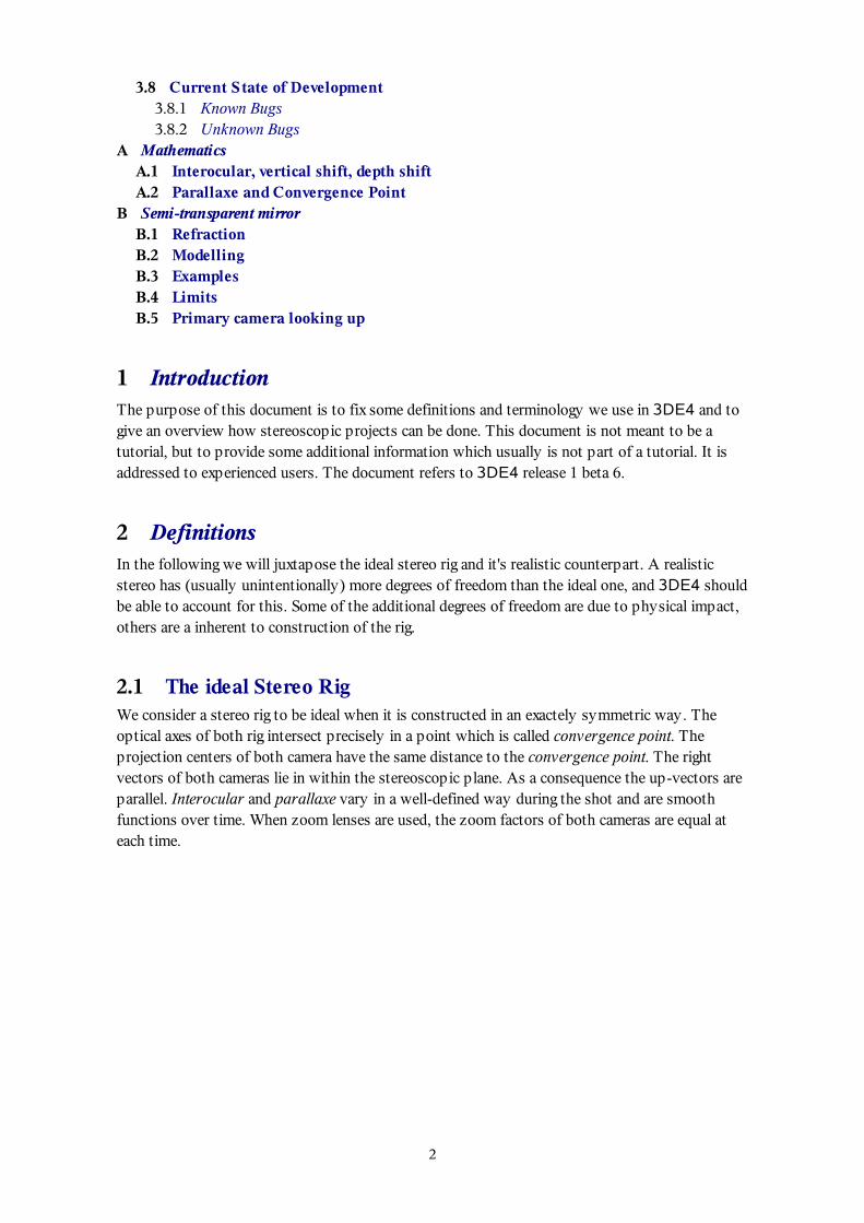
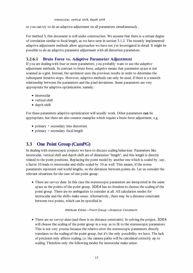
The following figure illustrates our definition of vertical shift and the convergence point inpresence of vertical shift. The rotation policy in this case is y, which means, both axes of viewand right vectors rotate within parallel planes.
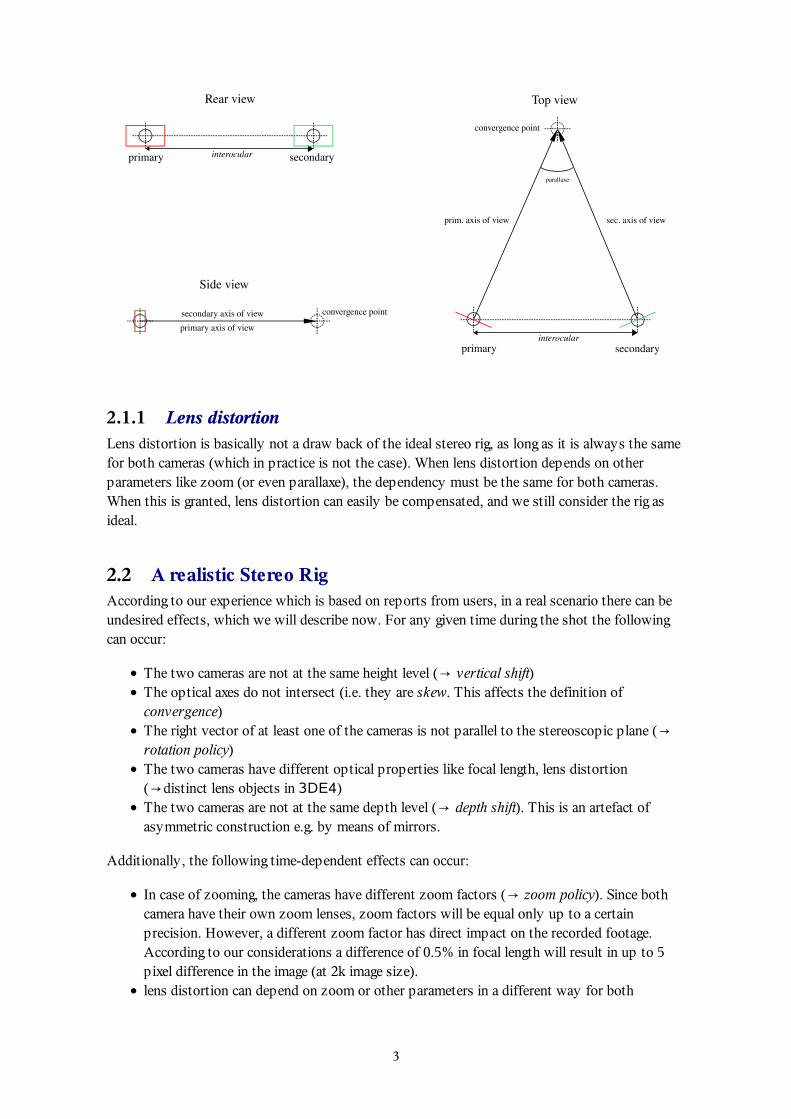
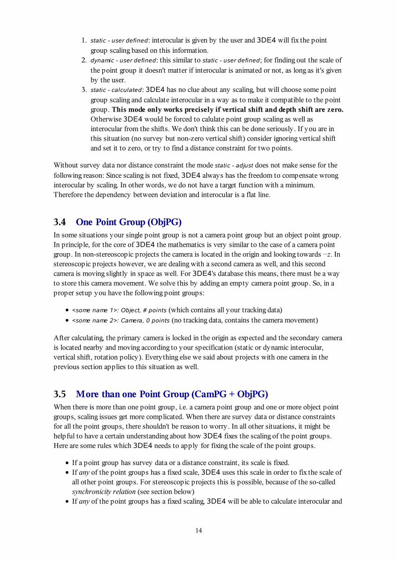
In the next figure you see a combination of vertical shift, depth shift and rotation policy xyz.Note, that the axis of view and the right vector of the secondary camera do not rotate within thestereoscopic plane.
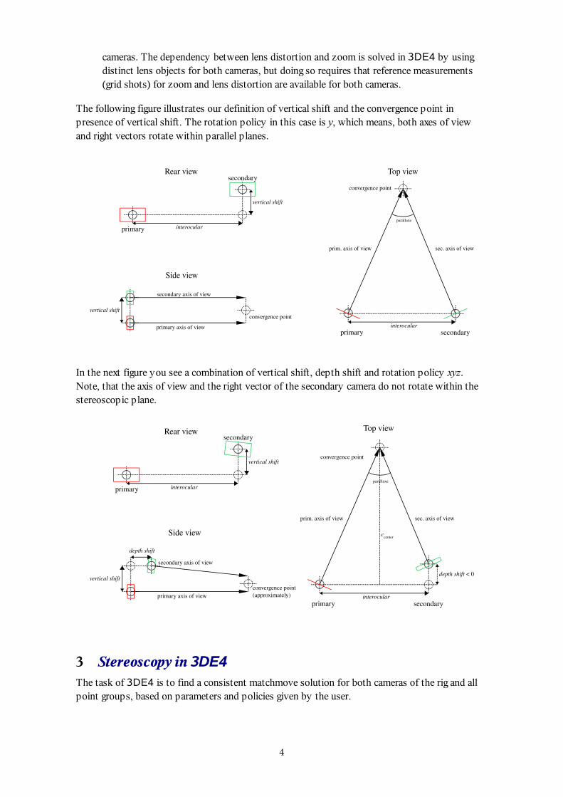
3 Stereoscopy in 3DE4The task of 3DE4 is to find a consistent matchmove solution for both cameras of the rig and allpoint groups, based on parameters and policies given by the user.
4
3.1 Basic SetupA stereoscopic project in 3DE4 consists of two stereo cameras (left one and right one) andpossibly other non-stereoscopic camera objects like reference cameras or further sequencecameras. Most of the camera properties (exception: zoom policy) are specified in
Attribute Editor→Cameras→Stereoscopic
Stereoscopic calculations are basically done by 3DE4's core in two distinct passes: In the firstpass the path of one of the two stereo cameras is calculated with respect to the camera pointgroup (along with reference cameras and non-stereoscopic cameras) if there is one. We call thisthe primary camera. Then the other stereoscopic camera is added and both camera paths areoptimized simultaneously. We call this the secondary camera. While the primary camera mustbe fully equipped with tracking data, this is not required for the secondary camera, although it ishighly recommended to provide comprehensive tracking data for the latter as well. As part of thebasic setup the user specifies which of the stereoscopic camera is primary and which issecondary, and which of the cameras is left-hand and which is right-hand. So, every stereoscopicproject contains a set of cameras with the following properties:
primary - left-hand
secondary - right-hand
or
primary - right-hand
secondary - left-hand.
When both cameras are equipped with a sufficient amount of tracking data, you can disable eitherof them separately, turning the project into a standard non-stereoscopic project. This isimportant for trouble-shooting ("divide-and-conquer").
3.1.1 Classification of 3DE4-projectsWe consider a project as more complex, if there are more occasions to make mistakes. Thisapplies to the user as well as the developer. In so far we come to the following hierarchy ofcomplexity:
Non-stereoscopic projects↓
Stereoscopic projects with one point group↓
Stereoscopic projects with more than one point group
We mention this because it reflects the way to get along when problems occur. Clearly, ourclassification is simplified. More classification could be added, and the result would not be asimple sequence like this one. But the general rule is:
If there is trouble with some complex project, reduce it to a simpler one until you find theerror.
This means, for instance, to disable a point group or to disable either primary or secondarycamera. The same hierarchy can be used for building a project; you start with a simple,non-stereoscopic setup. When this works fine, add a camera and specify primary and secondary.
5
If this works as well add the second point group. Of course, in real-life production often there islittle time for experiments, but for less experienced users, we consider this the best way.
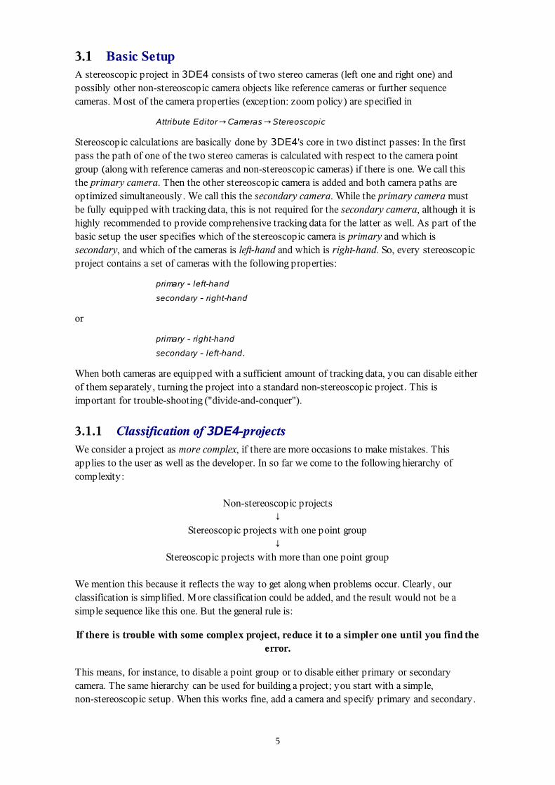
3.1.2 Single lens vs. separate lensesIn setting up a stereo project at some point you will decide if both camera objects are connectedto the same or to two different lens objects. Clearly, for modelling an ideal rig one lens object isused for both cameras. In practice however, there are good reasons to use a distinct lens for eachcamera. Generally, we do not know in how far the physical properties of the left and right cameracoincide. Experience shows that suspiciousness is advisable. The drawback of using a second lensis, that you have at least one parameter more to adjust, namely the focal length. In contrast tonon-stereoscopic projects there is an addidional aspect which we will discuss in the following.When you adjust both focal lengths using the brute force method, you might get a result like thefollowing (top view):
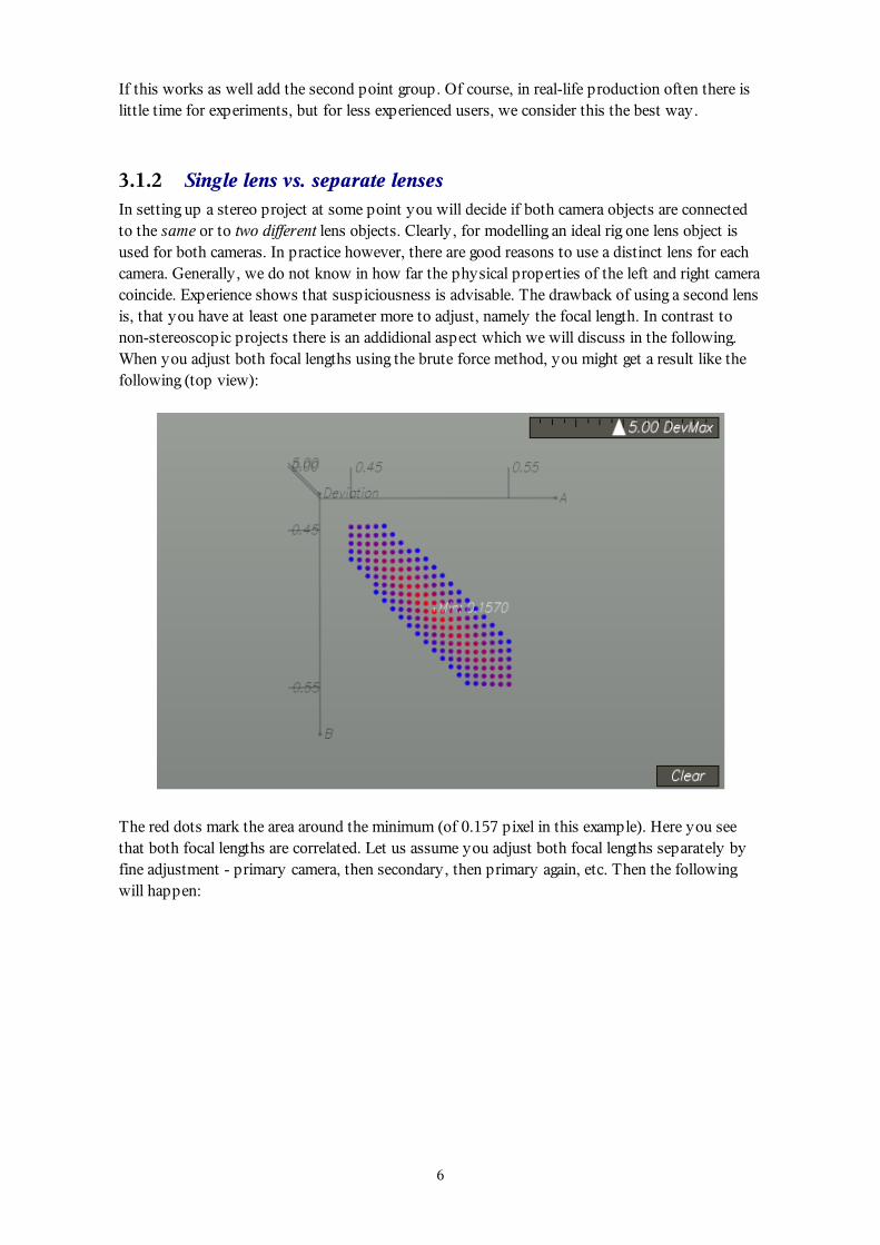
The red dots mark the area around the minimum (of 0.157 pixel in this example). Here you seethat both focal lengths are correlated. Let us assume you adjust both focal lengths separately byfine adjustment - primary camera, then secondary, then primary again, etc. Then the followingwill happen:
6
Slow convergence when focal lengths are optimized separately.
The red line represents the path of the system during parameter adjustment. Horizontal segmentsmean the primary focal length is adjusted, vertical lines represent adjustments of the secondarycamera. Each of the line segments stands for a complete one parameter adjustment with, say, 20attempts. The entire procedure will converge very slowly. This leads us to some cooking recipefor adjusting focal lengths:
In stereoscopic projects with two lens objects adjust both focal lengths simultaneously,not separately.
This rule applies for both, the brute force method as well as the adaptive method. Adjusting bothfocal lengths simultaneously is a gain in performance and precision. There is however anotherway to obtain both focal lengths. You can e.g. disable the secondary sequence and do a parameteradjustment with the primary camera only. Then turn on the secondary camera again and do a fineor custom parameter adjustment with the secondary focal length. This will also lead to areasonable result, but if you really want to be sure to find the optimum values, the method ofchoice is to adjust both focal lengths simultaneously as described before.
3.2 Parameters and PoliciesThis section describes where the various parameters and policies are specified within 3DE4'suser interface.
3.2.1 InterocularAs described before, by interocular we understand the distance of the camera projection centersin an ideal rig. In the realistic model it is the length of the distance vector of the two camerapositions projected into the stereoscopic plane and projected into the plane perpendicular to thecentral direction of view. 3DE4 allows various modes for calculating or specifying thisparameter. Interocular can be either time-independent ("static") or time-dependent ("dynamic").We will discuss the modes in detail. The interocular mode is specified in
Attribute Editor→Cameras→Stereoscopic→Interocular
It is associated to the primary camera, i.e. you can edit it when the primary camera is selected.There are four modes:
7
Static - User Defined
Static - Calculated
Static - Adjust
Dynamic - User Defined
These modes have the following effects:
Static - User Defined - Interocular is not time-dependent. "User defined" means the value isdirectly entered in the text field right to the option menu. When interocular is prescribed byproduction or predefined for instance by a data sheet this mode makes sense. Wheneverstereoscopic calculations are performed, this interocular is used in aligning the secondarycamera.Static - Calculated - In this mode, interocular is not time-dependent as well, but calculatedinternally whenever the stereoscopic calculations are performed. This mode makes sense,when no survey data are available, i.e. the scaling of the point group is completelyundefined. 3DE4 will fix the scaling at some point during the calculation, but since scalingis directly correlated with interocular, 3DE4 needs to calculat interocular as well, which isthe purpose of this mode.Static - Adjust - Interocular is not time-dependent. When this is selected, a panel foradjusting interocular appears in the Parameter Adjustment Window . In this case interocularis optimized along with other parameters e.g. focal length or whatever parameter the userwants to be optimized.Dynamic - User Defined Interocular is time-dependent. The current release of 3DE4 isn't yetable to calculate dynamic interocular. Therefore, the interocular curve needs to be edited byhand or imported by script. In practice, sometimes interocular curve can be retrieved frommetadata of the camera rig, but lacks precision or is superimposed by other effects, whichoften makes it necessary to apply some filter or tweak it by hand. In order to import aninterocular curve for setting Dynamic - User Defined, the following script (or a similar one)can be used. It expects a data file with two columns, one for the frame index and one for theinterocular value for that frame.
import string
# This script imports an interocular curve# into the currently selected camera object.
id_camera = tde4.getCurrentCamera()id_curve = tde4.getCameraStereoInterocularCurve(id_camera)
# delete current curvetde4.deleteAllCurveKeys(id_curve)
filename = tde4.postFileRequester("Select data file","*")
# open will throw if this failsf = open(filename,"r");
for line in f:cols = string.split(line," ")tde4.createCurveKey(id_curve,[float(cols[0]),float(cols[1])])
8
f.close()
Script for importing dynamic interocular
3.2.1.1 Static adjust vs. Static calculated
In principal, the modes Static - Adjust and Static - Calculated should lead to the same value forinterocular. In practice, this is not always the case, since the methods to calculate interocular aredifferent for these modes. Strictly speaking Static - Adjust optimizes directly the deviation (→Deviation Browser) while Static - Calculated does not. Since the deviation is only weaklydependent of interocular in many projects the discrepancy can be a few percent. On the otherhand, the brute force method in Static - Adjust scans the parameter space with some finite stepsize, while Static - Calculated uses an adaptive method with much higher precision. If you aredoing a parameter adjustment with two or more other parameters, it makes sense to use Static -
Calculated instead of Static adjust because this reduces the number of parameters in the ParameterAdjustment Window and thus increases performance.
3.2.1.2 Sign conventionAs mentioned in the previous section, you have to specify, which of the two cameras is left-handand which is right-hand. By this you define the sign convention of interocular. A positive valuefor interocular means, the cameras are positioned as you specified in the setup of the project (i.e.the right-hand camera appears on the right hand side, and the left-hand camera on the lefthand-side), while a negative value swaps the camera positions. If you let 3DE4 calculateinterocular, the system may find out, that the arrangement of the two cameras was wrong (i.e. leftand right exchanged by mistake). In this case interocular will be negative, but the project can becalculated nonetheless.
3.2.2 Vertical ShiftThe current stereo rig model of 3DE4 allows compensation for static (i.e. not time-dependent)vertical shift. The vertical shift mode is specified in
Attribute Editor→Cameras→Stereoscopic→Vertical Shift
In the user interface it is associated to the primary camera, i.e. you can edit it when the primarycamera is selected. The two possible settings are:
Static - User Defined
Static - Adjust
When the menu is set to Static - User Defined, 3DE4 uses the value in the accompanying textfield. When set to Static - Adjust, a panel for this parameter appears in the Parameter Adjustment
Window and will be calculated by 3DE4. A positive value means, that the secondary camera isshifted in the positive y-axis expressed in coordinates of the primary camera. In parameteradjustment it turns out that the deviation often shows only a weak but clear dependency onvertical shift. Therefore, the value can either be optimized easily, or it is likely to be irrelevantand should be left zero. The following figure shows the result of a two parameter adjustment ofinterocular and vertical shift in the range between 2.8cm and 4.8cm for interocular and -1.0cm and+1.0cm for vertical shift.
9
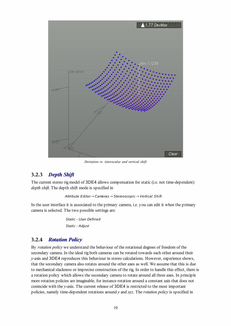
Deviation vs. interocular and vertical shift
3.2.3 Depth ShiftThe current stereo rig model of 3DE4 allows compensation for static (i.e. not time-dependent)depth shift. The depth shift mode is specified in
Attribute Editor→Cameras→Stereoscopic→Vertical Shift
In the user interface it is associated to the primary camera, i.e. you can edit it when the primarycamera is selected. The two possible settings are:
Static - User Defined
Static - Adjust
3.2.4 Rotation PolicyBy rotation policy we understand the behaviour of the rotational degrees of freedom of thesecondary camera. In the ideal rig both cameras can be rotated towards each other around theiry-axis and 3DE4 reproduces this behaviour in stereo calculations. However, experience shows,that the secondary camera also rotates around the other axes as well. We assume that this is dueto mechanical slackness or imprecise construction of the rig. In order to handle this effect, there isa rotation policy which allows the secondary camera to rotate around all three axes. In principlemore rotation policies are imaginable, for instance rotation around a constant axis that does notconincide with the y-axis. The current release of 3DE4 is restricted to the most importantpolicies, namely time-dependent rotations around y and xyz. The rotation policy is specified in
10
Attribute Editor→Cameras→Stereoscopic→Rotation Policy.
By definition (and mainly for compatibility reasons) we associate this property to the secondarycamera. There are two settings:
Allow y-Rotation Only
Allow Rotation Around all Axes
which correspond to our rotation policies y and xyz, respectively. In rotation policy y the opticalaxes of both cameras are parallel to the stereoscopic plane. In rotation policy xyz they can beskew. Mostly, when vertical shift is non-zero, you will use rotation policy xyz.
3.2.5 Zoom PolicyIn contrast to rotation policy, zoom policy is not specified as a parameter in some option menu.Rather, it is specified by the user exactly at the point when it comes to calculating the zoomcurve (or zoom curves). In an ideal rig both camera have the same focal length. In zoomed shotsthey also have the same time-dependent focal length, i.e. their zoom changes synchronuously.However, it has turned out in practice, that this is not always the case. This can be due toslackness or thermal deformation, since clearly we are talking about a mechanical system that isexposed to various kinds of physical influences on set, like solar (thermic) radiation, humidity,mechanical impact, abrasion etc. (we can only guess). Therefore we need to be able to calculatezoom for both primary and secondary camera separately. Moreover, it might be attractive to havea tool which tells you exactly, in how far the zoom factors differ, since this information might behelpful in order to correct either primary or secondary sequence. By appropriate scripts, 3DE4will give out this time-dependent ratio of primary and secondary zoom. As in non-stereoscopicprojects calculating the zoom curve is done in
Curve Editor→Calc→Zoom Curve→Calc Zoom Curve From Scratch
Curve Editor→Calc→Zoom Curve→Finetune Zoom Curve From Scratch
When you select one of these functions in a stereoscopic project 3DE4 will ask you to decidewhether both stereo cameras should be calculated with same or different zoom factor. The choicedepends on the stereo rig's construction and the above mentioned factors that might affectmechanical precision of the rig. Although the zoom of the primary camera can exhibit statistic andsystematic errors (depending on the project setup), we think that the relative zoom factorbetween primary and secondary camera is reconstruct very precisely. In other words, the errorsof primary and secondary zoom curve are highly correlated, while their ratio is calculatedprecisely. We have discussed this effect for static focal length in section 3.1.2. Since the ratio ofthe primary and secondary zoom curve is precise, we think that this could be used in order toapply zoom correction in the footage, although we do not have reports, that this is in fact done inpractice. Once zoom is calculated, you can export the corresponding curve with some pythonscript, like the following:
# This script exports the zoom curve# of the currently selected camera object.
id_camera = tde4.getCurrentCamera()id_curve = tde4.getCameraZoomCurve(id_camera)
filename = tde4.postFileRequester("Select data file","*")
11
# open will throw if this failsf = open(filename,"w");
id_key = tde4.getFirstCurveKey(id_curve)while id_key != None:
v = tde4.getCurveKeyPosition(id_curve,id_key)f.write("%f %f\n" % (v[0],v[1]));id_key = tde4.getNextCurveKey(id_curve,id_key)
f.close()
Script for exporting a zoom curve
It should be emphasized, that precision can be increased remarkably, if distinct lens objects areattached to primary and stereo camera, and if distinct zoom curves are calculated. The reason forthis is the high degree of correlation mentioned before, which originates from the stereoscopicconstraint.
3.2.6 Parameter AdjustmentIt is natural that there are many unknown parameters involved in stereoscopic projects. In orderto construct the worst case, let us assume you have two distinct lenses for either camera. Even incase of static focal length and static interocular we are left with the following scenario:
primary focal length: 1 parameterprimary lens distortion: 1 to 5 parameterssecondary focal length: 1 parametersecondar lens distortion: 1 to 5 parametersinterocular: 1 parametervertical shift: 1 parameterdepth shift: 1 parameter
which means, that in total, there can be 15(!) unknown parameters. It does not make sense to let3DE4 calculate them simultaneously in the Parameter Adjustment Window. Moreover, it isbetter to group these parameters and calculate them separately. Our objective is to separate lensdistortion calculations from stereoscopic. Let us recall the three methods for obtaining lensdistortion (as demonstrated in our online tutorial)
Calibration shots (grids) are given and you use 3DE4's Distortion Grid Controls1.Look for appropriate frames, which contain straight edges and use 3DE4's Distortion GridControls
2.
Optimize lens distortion by means of 3DE4's Parameter Adjustment Window3.
For methods 1 and 2 lens distortion is not a stereoscopic issue, since 3DE4's Distortion GridControls work on single cameras. In a large stereoscopic production you hopefully havecalibration shots for lens distortion, so we are left with a fine adjustment of two correlated focallengths plus interocular, vertical shift and depth shift. In practice you can improve your result bygrouping the parameters to be adjusted, e.g. like
primary focal, secondary focal, interocular
primary focal, secondary focal, vertical shift
primary focal, secondary focal, depth shift
12
interocular, vertical shift, depth shift
or you can try to do an adaptive adjustment on all parameters simultaneously.
For method 3, this document is still under construction. We assume that there is a certain degreeof correlation similar to focal length, as we have seen in section 3.1.2. The recently implementedadaptive adjustment methods allow approaches we have not yet investigated in detail. It might bepossible to do an adaptive parameter adjustment with all distortion parameters.
3.2.6.1 Brute Force vs. Adaptive Parameter AdjustmentIf you are dealing with four or more parameters, you probably want to use the adaptiveadjustment methods. In contrast to brute force, adaptive means that parameter space is notscanned as a grid. Instead, the optimizer uses the previous results in order to determine thesubsequent iterative steps. However, adaptive methods can only be used, if there is a smoothrelationship between the parameters and the pixel deviations. Some parameters are veryappropriate for adaptive optimization, namely:
interocularvertical shiftdepth shift
For these parameters adaptive optimization will usually work. Other parameters can beappropriate, but there are also counter examples which require a brute force adjustment, e.g
primary + secondary lens distortionprimary + secondary focal length
3.3 One Point Group (CamPG)In dealing with stereoscopic projects we have to discuss scaling behaviour. Parameters likeinterocular, vertical shift and depth shift are of dimension "length", and this length is directlyrelated to the point positions. Replacing the point model by another one which is scaled by, say,a factor 10 leads to interocular and shifts scaled by 10 as well. This means, if the stereoparameters represent real world lengths, so the distances between points do. Let us consider therelevant situations for the case of one point group:
There are survey data. In this case the stereoscopic parameters are interpreted in the samespace as the points of the point group. 3DE4 has no freedom to choose the scaling of thepoint group. There are no ambiguities to consider at all. All calculation modes forinterocular and the shifts make sense. Alternatively, there may be a distance constraintbetween two points, which can be specified in
Attribute Editor→Point Group→Distance Constraint
There are no survey data (and there is no distance constraint). In solving the project, 3DE4will choose the scaling of the point group in a way as to fit to the stereoscopic parameters.This is not very precise because the relative error the stereoscopic parameters directlytranslates to the scaling of the point group, but it's the only possibility we have. The lackof precision only affects scaling, i.e. the camera paths will be calculated correctly up toscaling. Therefore only the following modes for interocular make sense:
13
static - user defined: interocular is given by the user and 3DE4 will fix the pointgroup scaling based on this information.
1.
dynamic - user defined: this similar to static - user defined; for finding out the scale ofthe point group it doesn't matter if interocular is animated or not, as long as it's givenby the user.
2.
static - calculated: 3DE4 has no clue about any scaling, but will choose some pointgroup scaling and calculate interocular in a way as to make it compatible to the pointgroup. This mode only works precisely if vertical shift and depth shift are zero.Otherwise 3DE4 would be forced to calulate point group scaling as well asinterocular from the shifts. We don't think this can be done seriously. If you are inthis situation (no survey but non-zero vertical shift) consider ignoring vertical shiftand set it to zero, or try to find a distance constraint for two points.
3.
Without survey data nor distance constraint the mode static - adjust does not make sense for thefollowing reason: Since scaling is not fixed, 3DE4 always has the freedom to compensate wronginterocular by scaling. In other words, we do not have a target function with a minimum.Therefore the dependency between deviation and interocular is a flat line.
3.4 One Point Group (ObjPG)In some situations your single point group is not a camera point group but an object point group.In principle, for the core of 3DE4 the mathematics is very similar to the case of a camera pointgroup. In non-stereoscopic projects the camera is located in the origin and looking towards −z. Instereoscopic projects however, we are dealing with a second camera as well, and this secondcamera is moving slightly in space as well. For 3DE4's database this means, there must be a wayto store this camera movement. We solve this by adding an empty camera point group. So, in aproper setup you have the following point groups:
<some name 1>: Object, # points (which contains all your tracking data)<some name 2>: Camera, 0 points (no tracking data, contains the camera movement)
After calculating, the primary camera is locked in the origin as expected and the secondary camerais located nearby and moving according to your specification (static or dynamic interocular,vertical shift, rotation policy). Everything else we said about projects with one camera in theprevious section applies to this situation as well.
3.5 More than one Point Group (CamPG + ObjPG)When there is more than one point group, i.e. a camera point group and one or more object pointgroups, scaling issues get more complicated. When there are survey data or distance constraintsfor all the point groups, there shouldn't be reason to worry. In all other situations, it might behelpful to have a certain understanding about how 3DE4 fixes the scaling of the point groups.Here are some rules which 3DE4 needs to apply for fixing the scale of the point groups.
If a point group has survey data or a distance constraint, its scale is fixed.If any of the point groups has a fixed scale, 3DE4 uses this scale in order to fix the scale ofall other point groups. For stereoscopic projects this is possible, because of the so-calledsynchronicity relation (see section below)If any of the point groups has a fixed scaling, 3DE4 will be able to calculate interocular and
14
vertical shift.If there is no point group with a fixed scale, then 3DE4 uses interocular to calculate thescaling of all point groups. This is possible, since there are two cameras with predefinedgeometric relation (we know their distance in space).If there is neither survey data nor distance constraint nor predefined interocular, 3DE4fixes the scaling of the camera point group in some heuristic, hopefully reasonable way. Allother scalings and interocular result from this ad-hoc scaling.
For the following considerations it does not matter, what calculation mode we choose forinterocular or vertical shift (however, not static - calculated). Whatever modes are choosen 3DE4will call the underlying core with some set of parameters, either once or by brute-force scanningor (in later releases) some adaptive mode. When calculation starts for such a given set ofparameters, the core has to decide how to do the calculations, based on the following situations:
Survey data / distance constraints are available for all point groups
For all point groups the primary cameras are calculated by means of survey data1.For all point groups the secondry cameras are calculated. All stereoscopic parameters aregiven.
2.
Survey data / distance constraints are available for some of the point groups
For all point groups the primary cameras are calculated, either by means of survey data orusing survey-free methods.
1.
The core runs through all non-survey point groups. For each of these point groups a scalingfactor is calculated and applied to the point group.
2.
Survey data / distance constraints are not available for any of the point groups
For all point groups the primary cameras are calculated by means of survey-free methods.1.For one of the point groups (preferably the camera point group) the scale factor iscalculated. This includes calculating the secondary camera for this point group.
2.
For all other point groups the scaling factor and the secondary camera are calculated.3.
3.5.1 Trouble-shooting: Reducing the projectWhen you are encountering problems with a stereoscopic project, there are several ways toreduce the number of objects to be calculated. The idea is to differentiate whether problems resultfrom stereoscopy or from something else. You can:
Reduce the number of point groups. Often for trouble-shooting it makes sense to run thestereoscopic with a single point group only. Stereoscopic projects with one point groupprovide fewer occasions to make mistakes. Point groups can be disabled in the Object
Browser. This scenario is useful for getting an idea about camera parameters (focal length /zoom, lensdistortion) and stereoscopic parameters (interocular, vertical shift, secondaryfocal length / zoom).Reduce the number of cameras. For a stereoscopic project this means: disable thesecondary camera (see Object Browser). This turns the entire project into a normalnon-stereoscopic project. Now you can for instance let 3DE4 calculate the (primary) focallength / zoom, (primary) lens distortion etc. If this fails, it's not a stereosopic issue,because you have turned off stereo. If it works, calculate it and tweak it until your
15
experience with non-stereoscopic projects tells you know it's okay. Instead of disabling thesecondary camera you can also disable the primary camera. If there are enough tracking data3DE4 will treat this as a non-stereoscopic project.
If there are still problems, combine all methods and go back to a simple project with one camerapoint group. At some point it will become evident, what the problem is.
3.5.2 The Synchronicity Relation (SyncRel)By SyncRel we understand a relation which is obvious in the real world, but has to be explicitlyconstructed by 3DE4. On the user side, this is simply a test if 3DE4 has calculated correctly. Itoccurs when there are at least two point groups and at least two synchronuous cameras, as instereoscopic projects.Let us consider an example. Assume you have a blue box and a moving object and you need totrack both in stereoscopy. You get a camera point group and an object point group. Whencalculating all cameras, 3DE4 reconstructs the geometric relation between either of the twocameras and either of the point groups. For the camera point group this relation is simply thecamera path. For the object point group, it's the motion of the camera viewed from the object.Combining these motions we get the motion of the object point group relative to the camera pointgroup. The Synchronicity relation now says: this motion must be the same regardless if Iconstruct it via primary or secondary camera. You can test this on 3DE4 by doing the following:
Watch the object (point group) in 3DE4's 3D orientation panelToggle between the primary and the secondary sequence
If you do so, the object point group should not move, not even a little. Otherwise, there might bea programming error or 3DE4 was for some reason overburdoned calculating the project. Whenthis happens it might be helpful for user and developer to send the project to SDV's technicalsupport. The Synchronicity relation should be fulfilled after each type of stereoscopiccalculation, e.g. after postfiltering or finetuning.
3.6 Special ModesSome projects are calculated by special methods within 3DE4's core. This mainly affects theso-called "nodal shots", i.e. shots with fixed camera position constraint when no survey data aregiven. The special thing about these projects is, that they do not lead to a reliable point model. Innon stereoscopic projects, no real point positions are given, only directions with respect to theconstant camera position. Point positions cannot be triangulated because the parallaxe is zero dueto the constraint.
3.6.1 Stereoscopy on Nodal Shots, no SurveyIn stereoscopic projects, parallaxe is not zero and we cannot neglect it, since this would not resultin a true stereoscopic reconstruction of the camera rig. On the other hand, the parallaxe is small,since it is dependent on the ratio of interocular and convergence; the former is often very small incomparison to the latter. So, a point model based on the triangulation of a stereo pair willgenerally be less precise and reliable than a point model triangulated from an constrainted singlecamera. For this reason we decided to implement this as special mode in 3DE4. This mode isactivated when your project fulfills the following conditions:
16
There are exactly two cameras and they form a stereoscopic pair.Both have the Fixed Camera Position Constraint turned onThere is exactly one point group and it is a camera point group
The rotation policies y and xyz can both be used in this mode. Please do not provide survey datafor the points.
3.6.1.1 Parameter AdjustmentSince the scaling of the point group is not fixed, it does not make sense to do a parameteradjustment with interocular. If you do not know it, we recommend to set it to some reasonablevalue, like the default 6.5cm. With a fixed interocular it might be possible to adjust vertical shiftand depth shift, although we have notice from user projects, that there is not enough parallaxeinformation to do so.
3.6.1.2 Current state of developmentIn the present implementation the common pivot is exactly in the middle between primary andsecondary camera with respect to interocular, vertical shift and depth shift. 3DE4 constructs asolution by placing this pivot point in the origin. Calculating a zoom curve is not possible.
3.7 Stereoscopy in relation to other functions of 3DE4
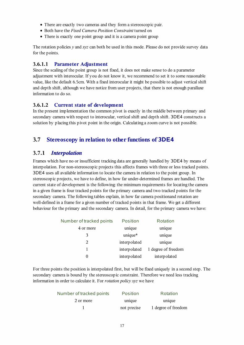
3.7.1 InterpolationFrames which have no or insufficient tracking data are generally handled by 3DE4 by means ofinterpolation. For non-stereoscopic projects this affects frames with three or less tracked points.3DE4 uses all available information to locate the camera in relation to the point group. Instereoscopic projects, we have to define, in how far under-determined frames are handled. Thecurrent state of development is the following: the minimum requirements for locating the camerain a given frame is four tracked points for the primary camera and two tracked points for thesecondary camera. The following tables explain, in how far camera positionand rotation arewell-defined in a frame for a given number of tracked points in that frame. We get a differentbehaviour for the primary and the secondary camera. In detail, for the primary camera we have:
Number of tracked points Position Rotation
4 or more unique unique
3 unique* unique
2 interpolated unique
1 interpolated 1 degree of freedom
0 interpolated interpolated
For three points the position is interpolated first, but will be fixed uniquely in a second step. Thesecondary camera is bound by the stereoscopic constraint. Therefore we need less trackinginformation in order to calculate it. For rotation policy xyz we have
Number of tracked points Position Rotation
2 or more unique unique
1 not precise 1 degree of freedom
17
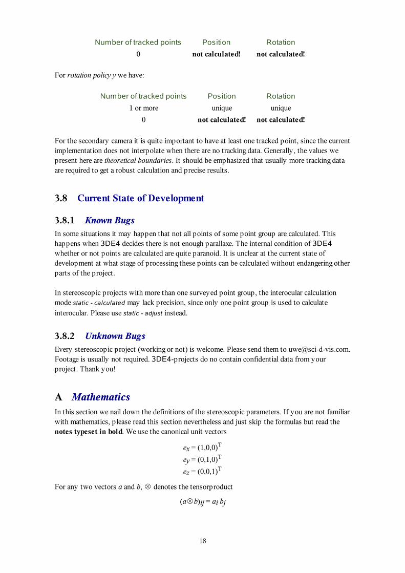
Number of tracked points Position Rotation
0 not calculated! not calculated!
For rotation policy y we have:
Number of tracked points Position Rotation
1 or more unique unique
0 not calculated! not calculated!
For the secondary camera it is quite important to have at least one tracked point, since the currentimplementation does not interpolate when there are no tracking data. Generally, the values wepresent here are theoretical boundaries. It should be emphasized that usually more tracking dataare required to get a robust calculation and precise results.
3.8 Current State of Development
3.8.1 Known BugsIn some situations it may happen that not all points of some point group are calculated. Thishappens when 3DE4 decides there is not enough parallaxe. The internal condition of 3DE4whether or not points are calculated are quite paranoid. It is unclear at the current state ofdevelopment at what stage of processing these points can be calculated without endangering otherparts of the project.
In stereoscopic projects with more than one surveyed point group, the interocular calculationmode static - calculated may lack precision, since only one point group is used to calculateinterocular. Please use static - adjust instead.
3.8.2 Unknown BugsEvery stereoscopic project (working or not) is welcome. Please send them to [email protected] is usually not required. 3DE4-projects do no contain confidential data from yourproject. Thank you!
A MathematicsIn this section we nail down the definitions of the stereoscopic parameters. If you are not familiarwith mathematics, please read this section nevertheless and just skip the formulas but read thenotes typeset in bold. We use the canonical unit vectors
ex = (1,0,0)T
ey = (0,1,0)T
ez = (0,0,1)T
For any two vectors a and b, ⊗ denotes the tensorproduct
(a⊗b)ij = ai bj
18
of these two vectors.
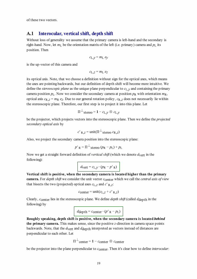
A.1 Interocular, vertical shift, depth shiftWithout loss of generality we assume that the primary camera is left-hand and the secondary isright-hand. Now, let mL be the orientation matrix of the left (i.e. primary) camera and pL its
position. Then
cL,y = mL ey
is the up-vector of this camera and
cL,z = mL ez
its optical axis. Note, that we choose a definition without sign for the optical axes, which meansthe axes are pointing backwards, but our definition of depth shift will become more intuitive. Wedefine the stereoscopic plane as the unique plane perpendicular to cL,y and containing the primary
camera position pL. Now we consider the secondary camera at position pR with orientation mR,
optical axis cR,z = mR ez. Due to our general rotation policy, cR,z does not necessarily lie within
the stereoscopic plane. Therefore, our first step is to project it into this plane. Let
Π⊥stereo = 1 − cL,y ⊗ cL,y
be the projector, which projects vectors into the stereoscopic plane. Then we define the projectedsecondary optical axis by
c' R,z = unit(Π⊥stereo cR,z)
Also, we project the secondary camera position into the stereoscopic plane:
p' R = Π⊥stereo (pR − pL) + pL
Now we get a straight forward definition of vertical shift (which we denote dvert in the
following):
dvert = cL,y ⋅ (pR − p' R)
Vertical shift is positive, when the secondary camera is located higher than the primarycamera. For depth shift we consider the unit vector ccenter which we call the central axis of view
that bisects the two (projected) optical axes cL,z and c' R,z:
ccenter = unit(cL,z + c' R,z)
Clearly, ccenter lies in the stereoscopic plane. We define depth shift (called ddepth in the
following) by
ddepth = ccenter ⋅ (p' R − pL)
Roughly speaking, depth shift is positive, when the secondary camera is located behindthe primary camera. This makes sense, since the positive z-direction in camera space pointsbackwards. Note, that the dvert and ddepth interpreted as vectors instead of distances are
perpendicular to each other. Let
Π⊥center = 1 − ccenter ⊗ ccenter
be the projector into the plane perpendicular to ccenter. Then it's clear how to define interocular:
19
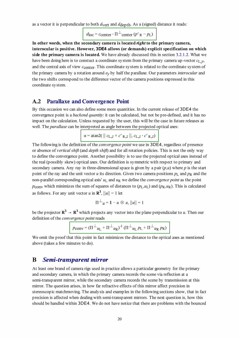
as a vector it is perpendicular to both dvert and ddepth. As a (signed) distance it reads:
dioc = ccenter ⋅ Π⊥center (p' R − pL)
In other words, when the secondary camera is located right to the primary camera,interocular is positive. However, 3DE4 allows (or demands) explicit specification on whichside the primary camera is located. We have already discussed this in section 3.2.1.2. What wehave been doing here is to constuct a coordinate system from the primary camera up-vector cL,y,
and the central axis of view ccenter. This coordinate system is related to the corrdinate system of
the primary camera by a rotation around ey by half the parallaxe. Our parameters interocular and
the two shifts correspond to the difference vector of the camera positions expressed in thiscoordinate system.
A.2 Parallaxe and Convergence PointBy this occasion we can also define some more quantities. In the current release of 3DE4 theconvergence point is a backend quantity: it can be calculated, but not be pre-defined, and it has noimpact on the calculation. Unless requested by the user, this will be the case in future releases aswell. The parallaxe can be interpreted as angle between the projected optical axes:
α = atan2( || cL,z × c' R,z ||, cL,z ⋅ c' R,z)
The following is the definition of the convergence point we use in 3DE4, regardless of presenceor absence of vertical shift (and depth shift) and for all rotation policies. This is not the only wayto define the convergence point. Another possibility is to use the projected optical axes instead ofthe real (possibly skew) optical axes. Our definition is symmetric with respect to primary andsecondary camera. Any ray in three-dimensional space is given by a pair (p,u) where p is the startpoint of the ray and the unit vector u its direction. Given two camera positions pL and pR and the
non-parallel corresponding optical axis' uL and uR we define the convergence point as the point
pconv which minimizes the sum of squares of distances to (pL,uL) and (pR,uR). This is calculated
as follows. For any unit vector u in R3, ||u|| = 1 let
Π⊥u = 1 − u ⊗ u, ||u|| = 1
be the projector R3 → R3 which projects any vector into the plane perpendicular to u. Then ourdefinition of the convergence point reads
pconv = (Π⊥uL + Π⊥uR)-1 (Π⊥uL pL + Π⊥uR pR)
We omit the proof that this point in fact minimizes the distance to the optical axes as mentionedabove (takes a few minutes to do).
B Semi-transparent mirrorAt least one brand of camera rigs used in practice allows a particular geometry for the primaryand secondary camera, in which the primary camera records the scene via reflection at asemi-transparent mirror, while the secondary camera records the scene by transmission at thismirror. The question arises, in how far refractive effects of this mirror affect precision instereoscopic matchmoving. The analysis and examples in the following sections show, that in factprecision is affected when dealing with semi-transparent mirrors. The next question is, how thisshould be handled within 3DE4. We do not have notice that there are problems with the bounced
20
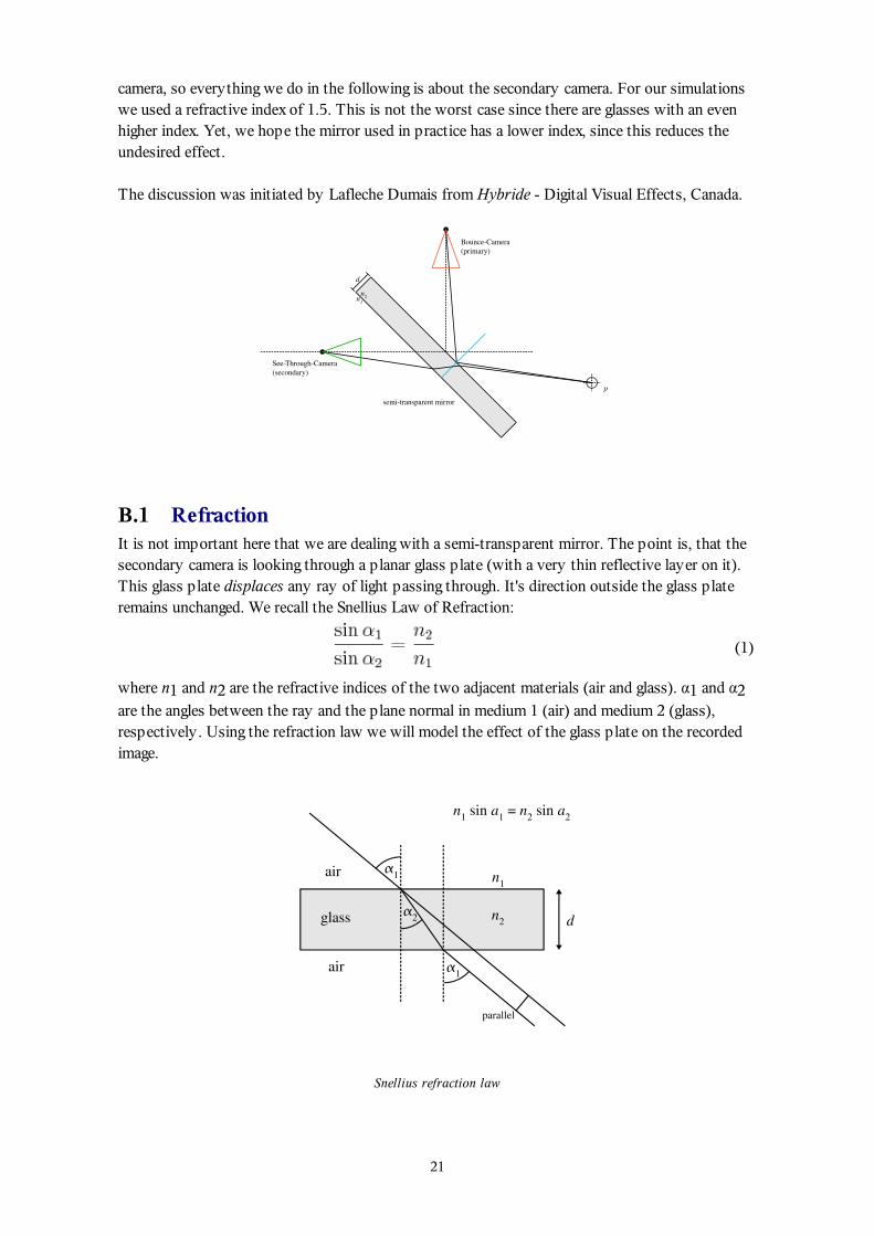
camera, so everything we do in the following is about the secondary camera. For our simulationswe used a refractive index of 1.5. This is not the worst case since there are glasses with an evenhigher index. Yet, we hope the mirror used in practice has a lower index, since this reduces theundesired effect.
The discussion was initiated by Lafleche Dumais from Hybride - Digital Visual Effects, Canada.
B.1 RefractionIt is not important here that we are dealing with a semi-transparent mirror. The point is, that thesecondary camera is looking through a planar glass plate (with a very thin reflective layer on it).This glass plate displaces any ray of light passing through. It's direction outside the glass plateremains unchanged. We recall the Snellius Law of Refraction:
(1)
where n1 and n2 are the refractive indices of the two adjacent materials (air and glass). α1 and α2are the angles between the ray and the plane normal in medium 1 (air) and medium 2 (glass),respectively. Using the refraction law we will model the effect of the glass plate on the recordedimage.
Snellius refraction law
21
B.2 ModellingWe will do the calculations in the coordinate system of the camera, i.e. the camera is located in theorigin and looking towards negative z-direction. Given an object point p recorded by the camerawith no glass plate, its direction with respect to the camera position is the unit vector from thecamera position to p:
(2)
The aim is to calculate a modified direction u' which represents the point direction when thecamera looks through the glass plate. Let n be the normal vector of the refractor and
(3)
the ratio of the refractive indices. We split the position of p into a normal part (parallel to n) anda tangential part (perpendicular to n):
(4)
where the normalized tangential vector t is
(5)
It will be useful later to express p by the angle with respect to n.
(6)
where
(7)
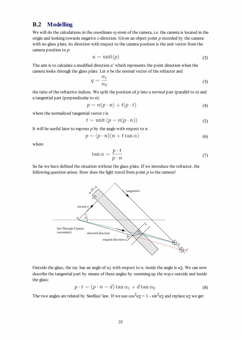
So far we have defined the situation without the glass plate. If we introduce the refractor, thefollowing question arises: How does the light travel from point p to the camera?
Outside the glass, the ray has an angle of α1 with respect to n, inside the angle is α2. We can now
describe the tangential part by means of these angles by summing up the ways outside and insidethe glass:
(8)
The two angles are related by Snellius' law. If we use cos2α2 = 1 - sin2α2 and replace α2 we get:
22
(9)
α1 represents the direction of p when the camera looks through the glass plate. Let us exmine this
result and check, if it shows a reasonable behaviour. We can expect, that this equation becomestrivial when either d = 0 (there is no plate) or q = 1 (there is no refraction). In fact, in either casewe get
(10)
which is correct. The above equation for α1 not very easy to solve analytically, since it leads to a
quartic equation in sin α1 (and we didn't try). The easiest way is to reformulate it as a fixed-point
problem and solve it numerically by two or three iterations:
(11)
where we get a good initial value from
(12)
This initial value reflects the fact that the effect of the refractor is quite small. Now we canconstruct some kind of vertex shader function f by replacing p by a new point p'. We do this byshifting p along the tangential vector t.
(13)
which completes our calculations. The shader function has a fixed point, namely at (p ⋅ n)n, whichmeans α = α1 = 0:
(14)
This fixed point is visualized in section B.4 where we investigate the (theoretical) limits of themirror construction. Note, that we had some freedom in choosing the position p'; we could haveused a different distance to the camera as well. Our shader function f does not reproduce normalvectors correctly (because we did not explicit construct it to do so). A detailed analysis wouldprobably show that the ambiguity in choosing the distance of p' can be utilized to implement thecorrect behavour of the shader function with respect to normal vectors. However, f as constructedabove provides all information we need in the following.
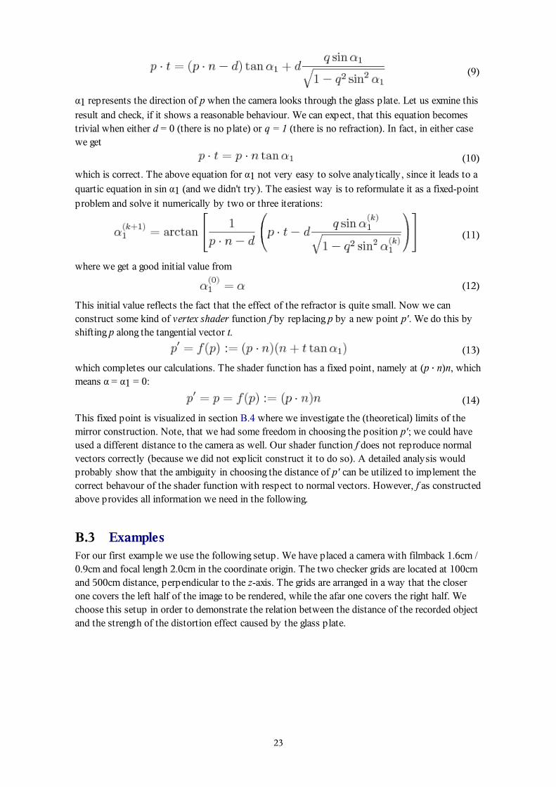
B.3 ExamplesFor our first example we use the following setup. We have placed a camera with filmback 1.6cm /0.9cm and focal length 2.0cm in the coordinate origin. The two checker grids are located at 100cmand 500cm distance, perpendicular to the z-axis. The grids are arranged in a way that the closerone covers the left half of the image to be rendered, while the afar one covers the right half. Wechoose this setup in order to demonstrate the relation between the distance of the recorded objectand the strength of the distortion effect caused by the glass plate.
23
Two grids at 100cm and 500cm distance to camera
The resulting image is:
Undistorted image of two grids at 100cm and 500cm distance to camera
Now we simulate a glass plate, e.g. a semitransparent mirror. The refractive index is 1.5, and itsthickness is 0.25cm. Its normal vector points towards (0,1,-1).
24
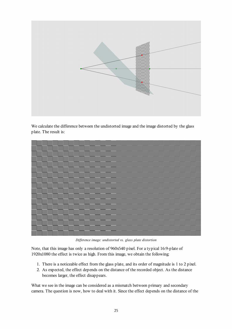
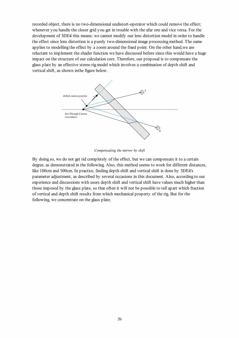
We calculate the difference between the undistorted image and the image distorted by the glassplate. The result is:
Difference image: undistorted vs. glass plate distortion
Note, that this image has only a resolution of 960x540 pixel. For a typical 16:9-plate of1920x1080 the effect is twice as high. From this image, we obtain the following:
There is a noticeable effect from the glass plate, and its order of magnitude is 1 to 2 pixel.1.As expected, the effect depends on the distance of the recorded object. As the distancebecomes larger, the effect disappears.
2.
What we see in the image can be considered as a mismatch between primary and secondarycamera. The question is now, how to deal with it. Since the effect depends on the distance of the
25
recorded object, there is no two-dimensional undistort-operator which could remove the effect;whenever you handle the closer grid you get in trouble with the afar one and vice versa. For thedevelopment of 3DE4 this means: we cannot modify our lens distortion model in order to handlethe effect since lens distortion is a purely two-dimensional image processing method. The sameapplies to modelling the effect by a zoom around the fixed point. On the other hand,we arereluctant to implement the shader function we have discussed before since this would have a hugeimpact on the structure of our calculation core. Therefore, our proposal is to compensate theglass plate by an effective stereo rig model which involves a combination of depth shift andvertical shift, as shown inthe figure below.
Compensating the mirror by shift
By doing so, we do not get rid completely of the effect, but we can compensate it to a certaindegree, as demonstrated in the following. Also, this method seems to work for different distances,like 100cm and 500cm. In practice, finding depth shift and vertical shift is done by 3DE4'sparameter adjustment, as described by several occasions in this document. Also, according to ourexperience and discussions with users depth shift and vertical shift have values much higher thanthose imposed by the glass plate, so that often it will not be possible to tell apart which fractionof vertical and depth shift results from which mechanical property of the rig. But for thefollowing, we concentrate on the glass plate.
26
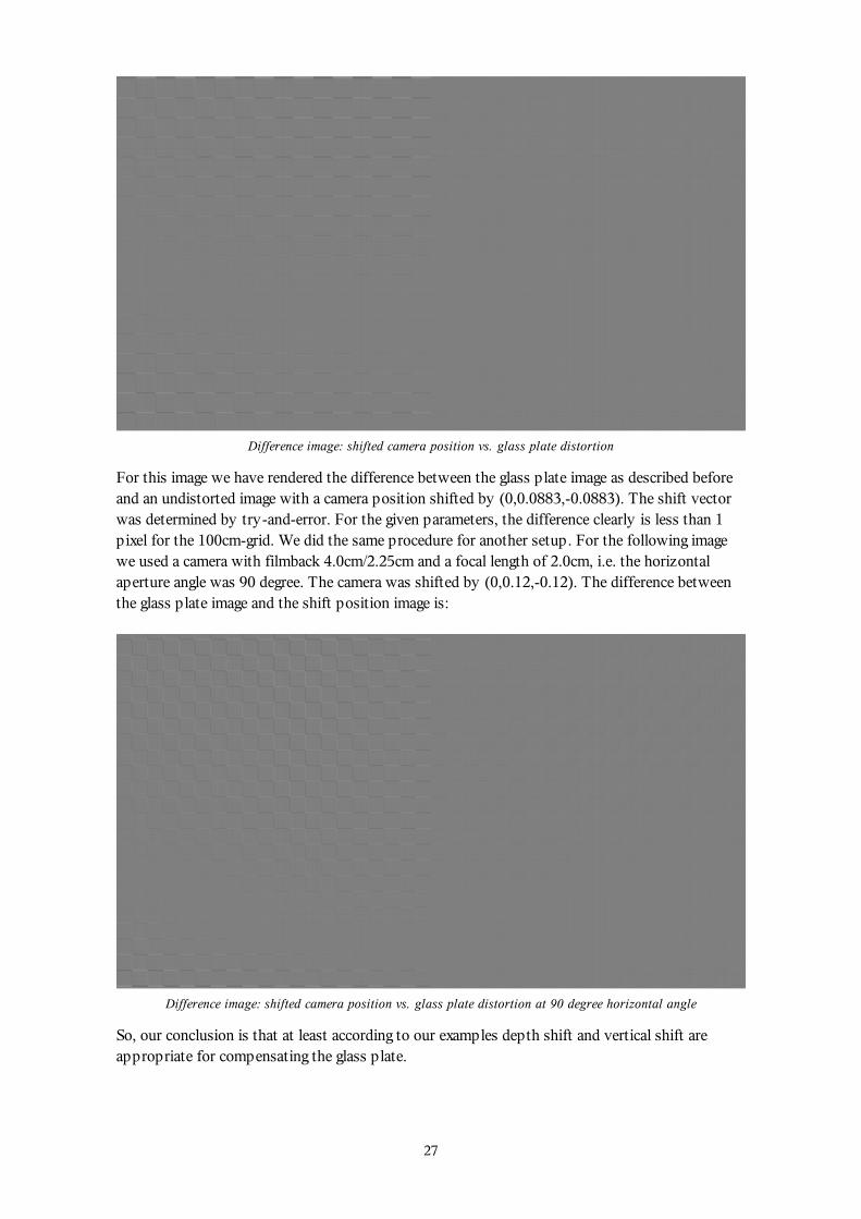
Difference image: shifted camera position vs. glass plate distortion
For this image we have rendered the difference between the glass plate image as described beforeand an undistorted image with a camera position shifted by (0,0.0883,-0.0883). The shift vectorwas determined by try-and-error. For the given parameters, the difference clearly is less than 1pixel for the 100cm-grid. We did the same procedure for another setup. For the following imagewe used a camera with filmback 4.0cm/2.25cm and a focal length of 2.0cm, i.e. the horizontalaperture angle was 90 degree. The camera was shifted by (0,0.12,-0.12). The difference betweenthe glass plate image and the shift position image is:
Difference image: shifted camera position vs. glass plate distortion at 90 degree horizontal angle
So, our conclusion is that at least according to our examples depth shift and vertical shift areappropriate for compensating the glass plate.
27
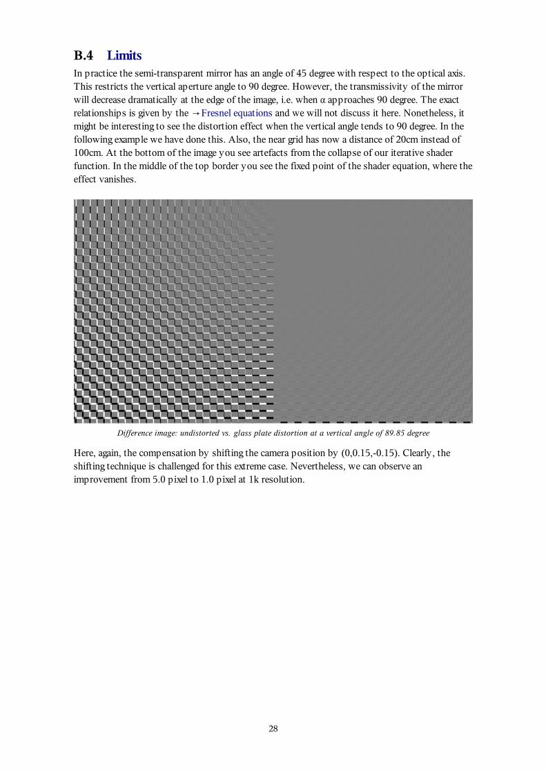
B.4 LimitsIn practice the semi-transparent mirror has an angle of 45 degree with respect to the optical axis.This restricts the vertical aperture angle to 90 degree. However, the transmissivity of the mirrorwill decrease dramatically at the edge of the image, i.e. when α approaches 90 degree. The exactrelationships is given by the →Fresnel equations and we will not discuss it here. Nonetheless, itmight be interesting to see the distortion effect when the vertical angle tends to 90 degree. In thefollowing example we have done this. Also, the near grid has now a distance of 20cm instead of100cm. At the bottom of the image you see artefacts from the collapse of our iterative shaderfunction. In the middle of the top border you see the fixed point of the shader equation, where theeffect vanishes.
Difference image: undistorted vs. glass plate distortion at a vertical angle of 89.85 degree
Here, again, the compensation by shifting the camera position by (0,0.15,-0.15). Clearly, theshifting technique is challenged for this extreme case. Nevertheless, we can observe animprovement from 5.0 pixel to 1.0 pixel at 1k resolution.
28
Difference image: shifted camera position vs. glass plate distortion at a vertical angle of 89.85 degree
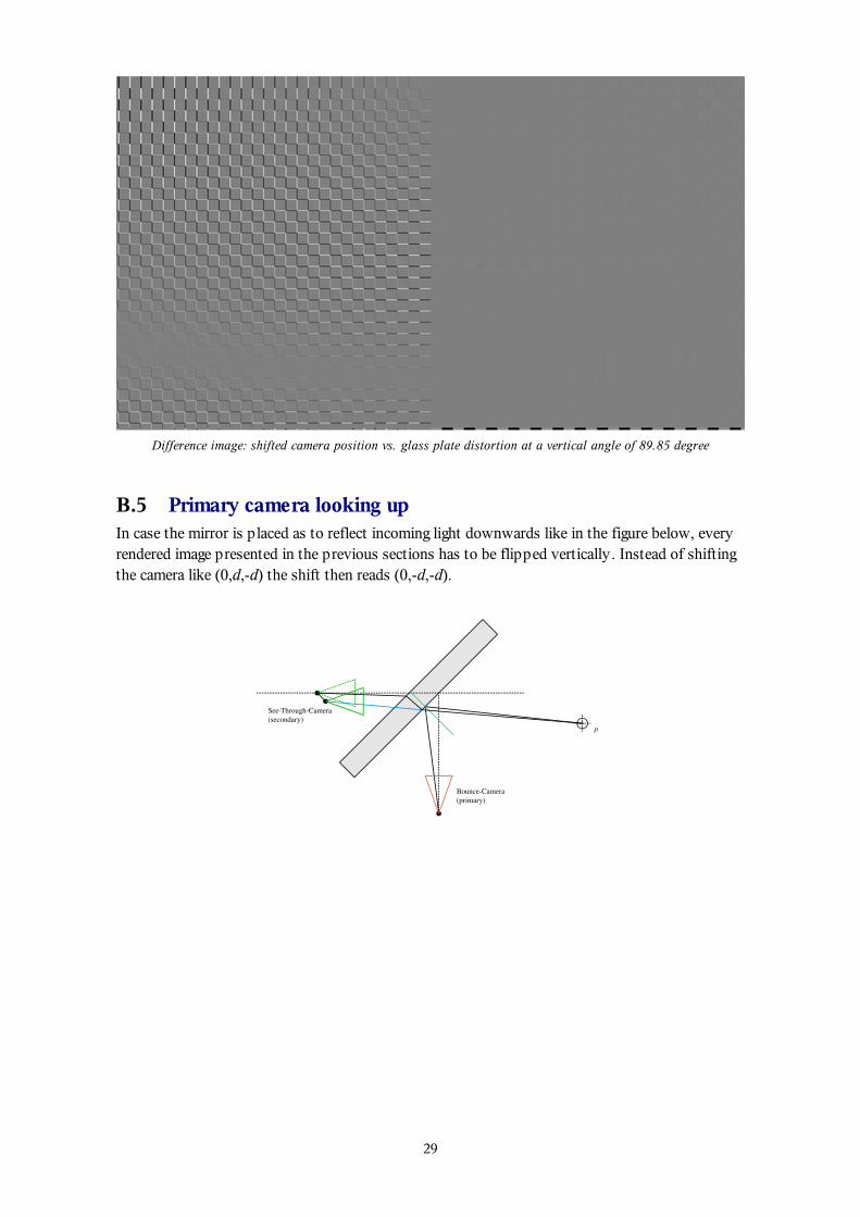
B.5 Primary camera looking upIn case the mirror is placed as to reflect incoming light downwards like in the figure below, everyrendered image presented in the previous sections has to be flipped vertically. Instead of shiftingthe camera like (0,d,-d) the shift then reads (0,-d,-d).
29