Embed Size (px)
Citation preview

Chapter 2
History of Stereolithographic Processes
Paulo Jorge Bartolo and Ian Gibson
2.1 Introduction
There are a number of processes that can realize three-dimensional (3D) shapes
such as those stored in the memory of a computer. An example is the use of
holographic techniques [1], but these require many complex calculations to obtain
the hologram and there is insufficient accuracy and clarity. A manual or a conven-
tional mechanical process can also make a physical model, but such models require
long fabricating times, high cost and excessive labor. To solve these kinds of
problems, a new group of techniques called additive manufacturing (AM) technol-
ogies have been developed over the last 10 numbers [2–14].
AM is a collection of processes inwhich physical objects are quickly created directly
from computer generated models. The basic concept of rapid prototyping is where 3D
structures are formed by laminating thin layers according to two-dimensional (2D)
slice data, obtained from a 3Dmodel created on a CAD/CAM system [2–15].
Stereolithography is one of the most popular AM process. It usually involves the
curing or solidification of a liquid photosensitive polymer by a laser beam scanned
across its surface. The laser supplies energy that induces a chemical reaction, bonding
large number of small molecules and forming a highly cross-linked polymer [16].
2.2 The Importance of a Prototype
In today’s highly competitive marketplace with short life cycles of products,
developing a new product to meet consumers’ needs in a shorter lead time is very
important for an enterprise. Facing this environment, the strategy of developing
a product is transformed from “product-push” type to “market-pull”. Thus, to
P.J. Bartolo (*)
Centre for Rapid and Sustainable Product, Polytechnic Institute
of Leiria, Leiria, Portugal
e-mail: [email protected]
P.J. Bartolo (ed.), Stereolithography: Materials, Processes and Applications,DOI 10.1007/978-0-387-92904-0_2, # Springer Science+Business Media, LLC 2011
37

improve competitiveness, a product should not only satisfy consumers’ physical
requirements, but also should satisfy their needs, increasing the product complexity
and reducing its lifetime [16, 17] as shown in Fig. 2.1. Besides, market segmenta-
tion has resulted in demand from individualistic consumers, which has led to the
concept of “niche markets” increasing product choice [18]. Moreover, companies
must meet customer expectations in terms of improved quality and lower cost of
products. These new strategies adopted by modern companies lead to a tremendous
change in their internal flexibility. As a consequence, the current industrial trend is
moving from mass production, i.e. high volume and small range of products for
manufacturing, to small volume and a wide range of products [18].
As a consequence of the increasing globalization, companies are now facing
competition from low cost and newly industrialized countries putting market prices
under pressure [16, 19]. Besides, technology development is increasing rapidly and
ecological factors also became important sources of pressure [19]. International
markets are therefore highly volatile and competition is brutal, imposing new
demands on the innovative ability of companies. Moreover, it becomes increasingly
important to rapidly develop new and successful products, requiring changes on
how a product is developed. Thus, different groups in a company must cooperate
more closely towards a common goal. This must be clear to everyone involved, and
if cooperation is to be effective, it is essential to avoid communication problems [3].
Product lifetime
1980 1990 2000
Number of variants
1980 1990 2000
Product complexity
1980 1990 2000
Required lead-time
1980 1990 2000
Fig. 2.1 Changes in the manufacturing industry during the last 30 years [17]
38 P.J. Bartolo and I. Gibson
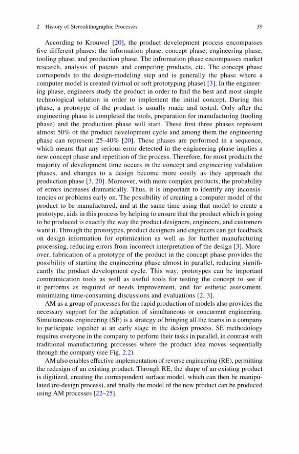
According to Krouwel [20], the product development process encompasses
five different phases: the information phase, concept phase, engineering phase,
tooling phase, and production phase. The information phase encompasses market
research, analysis of patents and competing products, etc. The concept phase
corresponds to the design-modeling step and is generally the phase where a
computer model is created (virtual or soft prototyping phase) [3]. In the engineer-
ing phase, engineers study the product in order to find the best and most simple
technological solution in order to implement the initial concept. During this
phase, a prototype of the product is usually made and tested. Only after the
engineering phase is completed the tools, preparation for manufacturing (tooling
phase) and the production phase will start. These first three phases represent
almost 50% of the product development cycle and among them the engineering
phase can represent 25–40% [20]. These phases are performed in a sequence,
which means that any serious error detected in the engineering phase implies a
new concept phase and repetition of the process. Therefore, for most products the
majority of development time occurs in the concept and engineering validation
phases, and changes to a design become more costly as they approach the
production phase [3, 20]. Moreover, with more complex products, the probability
of errors increases dramatically. Thus, it is important to identify any inconsis-
tencies or problems early on. The possibility of creating a computer model of the
product to be manufactured, and at the same time using that model to create a
prototype, aids in this process by helping to ensure that the product which is going
to be produced is exactly the way the product designers, engineers, and customers
want it. Through the prototypes, product designers and engineers can get feedback
on design information for optimization as well as for further manufacturing
processing, reducing errors from incorrect interpretation of the design [3]. More-
over, fabrication of a prototype of the product in the concept phase provides the
possibility of starting the engineering phase almost in parallel, reducing signifi-
cantly the product development cycle. This way, prototypes can be important
communication tools as well as useful tools for testing the concept to see if
it performs as required or needs improvement, and for esthetic assessment,
minimizing time-consuming discussions and evaluations [2, 3].
AM as a group of processes for the rapid production of models also provides the
necessary support for the adaptation of simultaneous or concurrent engineering.
Simultaneous engineering (SE) is a strategy of bringing all the teams in a company
to participate together at an early stage in the design process. SE methodology
requires everyone in the company to perform their tasks in parallel, in contrast with
traditional manufacturing processes where the product idea moves sequentially
through the company (see Fig. 2.2).
AM also enables effective implementation of reverse engineering (RE), permitting
the redesign of an existing product. Through RE, the shape of an existing product
is digitized, creating the correspondent surface model, which can then be manipu-
lated (re-design process), and finally the model of the new product can be produced
using AM processes [22–25].
2 History of Stereolithographic Processes 39

2.3 Techniques to Produce Prototypes
The traditional way to make a physical model or prototype, besides hand-made
wood or clay models, is to use numerically controlled machines as CNC (computer
numerical control) milling, electric-discharge machining, turning, and grinding
machines [26, 27].
In such processes, the object is revealed by cutting away material from a starting
block and therefore these processes are called subtractive methods [3, 26–28].
While conventional machine tools are usually effective in producing the desired
object, they are deficient in many respects. First, a large amount of waste material
for disposal is produced. Further, such methods usually require expensive object-
specific tooling, the setting up of machining protocols, and generation and pro-
gramming of 3D tool paths which all require much time and a great deal of human
judgement and expertise. The cost and time to set up and run machine-specific
tooling, along with the initial costs for tooling, make conventional manufac-
turing processes both time and cost intensive for small productions like models or
prototypes [28].
The final difficulty associated with such processes is the impossibility of making
special object configurations [3, 26, 27]. Effectively, these conventional methods
are usually best suited for producing symmetrical objects and objects where only
the exterior is machined. However, when a desired object has an unusual shape or
specific internal features, the machining becomes more difficult and quite often the
Simultaneous engineering
Traditional manufacturing system
Design Process planning Manufacturing
Design
Process planning
Manufacturing
RPT models
Fig. 2.2 Comparison between the traditional manufacturing system and the new manufacturing
approach through AM technologies [21]
40 P.J. Bartolo and I. Gibson

object must be divided into segments for production [3, 26, 27]. In many cases,
a particular object configuration is not possible because of the limitations imposed
upon the tool.
Other important classes of conventional manufacturing processes are the
so-called formative methods [3], e.g. casting, injection molding, compressive mol-
ding, etc. Through these processes the material is forced into the desired shape
using molds, in which the material is made to harden and solidify. However, these
processes are still often highly expensive, time consuming, and require a broad
range of expertise.
Recently, AM emerged as a step forward in the product cycle, reducing lead times
for new products, aswell as improving designmanufacturing and tooling costs [2–14].
In AM, a single automated system can be used to produce models directly from
engineering designs. Such systems are limited only by the size of the model and not
by its complexity [2, 3].
AM technologies are additive methods [2–14] because they build objects layer
by layer, and as a consequence they are also generally known as Layered
Manufacturing Techniques [8, 9]. AM processes are similar processes to 2D printing
and plotting technologies using both vector-based and raster-based imaging techni-
ques. The various AM processes include laser sintering, lamination, extrusion, ink-jet
printing, and photolithographic systems [2–14, 16]. AM technologies have been
mainly used for [2–5, 13, 16, 29–38]:
l Physical verification of a previously defined CAD modell Form, fit, and function testingl Creating models without regard to draft angles, parting lines, etcl Concept presentations and design reviewsl Direct tooling as well as masters for rapid tooling, using conversion technologies
such as investment casting and silicone, epoxy and spray metal moldsl Reducing time-to-marketl Creating anatomical models constructed from computer-aided tomography data
for surgical planning, prosthesis design, scaffolds for tissue engineering and
dental implantsl Producing relief models for geographical applicationsl Creating 3D portraits (three-dimensional photography) using data produced by
3D shape digitizing technology.
2.4 Stereolithographic Processes
Photolithographic systems build shapes using light to selectively solidify photosen-
sitive resins. There are two basic approaches:
l Laser lithographyl Photo-mask
2 History of Stereolithographic Processes 41

The laser lithography (or Stereolithography) approach is currently one of the most
used AM technologies. Models are defined by scanning a laser beam over a photo-
polymer surface. Photo-mask systems build models by shining a flood lamp
through a mask, which lets light through it and is a method commonly employed in
microlithography.
2.4.1 History and Developmentof the Photolithographic Systems
Lithography is the art of reproduction of graphic objects and comprises different
techniques, such as photographic reproduction, photosculpture, xerography and
microlithography. Modern photolithographic AM systems harness the principle of
computer generated graphics combined with photosensitive materials to produce
3D objects.
Photosensitive materials have been known at least since the time of the ancient
Egyptians and probably long before them. The alchemists of the Middle Ages and
Renaissance knew about the phenomena of blackening silver salts by light expo-
sure. However, they did not realize that this phenomenon was due solely to the
Sun’s light and not to its heat. In fact, they argued that all changes produced in
bodies exposed to sunlight were due to heat and not to light [39].
In 1775, Schultz discovered that a silver-containing precipitate used to produce
phosphorous, turned purple when illuminated by sunlight, whilst the portion turned
away from the light remained white. After that, he divided the mixture into two lots,
one of which he kept in the dark, exposing the other to sunlight, with a thin cord tied
round the bottle, and again a change in the precipitate exposed to the sunlight was
observed. He repeated the experiment by covering the bottle with paper from which
he had cut out words and entire sentences, this way “writing” the words and
sentences in the solution [39].
Another remarkable achievement was due to Niepce (1822), when he made his
first successful and permanent copy of an engraving of Pope Pius VII [39].
He dissolved bitumen of Judea in oil of lavender, and spread a thin layer on a
glass plate on which he superimposed an engraving of Pope Pius VII made transpar-
ent by oiling. After exposure to light, the bitumen under the white parts of the
engraving became hard, whilst that under the dark lines remained soluble [34, 39].
2.4.1.1 Origins of Modern Stereolithography
The first significant work associated with modern photolithographic AM systems
only emerged during the 1970s [8, 10]. In 1971, Swainson [40] presented a patent
for a system where two intersecting beams of radiation produce a phase change in
42 P.J. Bartolo and I. Gibson

a material to build 3D objects. The essential features of this process, named
photochemical machining [41], are illustrated in Fig. 2.3. The object through
this process can be formed by either photochemically cross-linking or degrading
a polymer [42–44]. However, the major problem of this process was due to the
photonic absorption by the photopolymeric system used, which occurs somewhere
along the paths of each laser, initiating polymerisations in spots that differ from
the planned ones [41]. In the 1980s, the idea was abandoned due to funding
problems, without achieving optimum working parameters, adequate materials,
and good accuracy of final models [34].
Kodama [45] described an automatic method for fabricating 3D models in
layered stepped stages using a photosensitive polymer. Light capable of curing
the polymer was directed onto the surface, and the desired shape of a layer was
created by using an appropriate mask (Fig. 2.4a, b) or an optical fiber manipulated
by an X–Y plotter (Fig. 2.4c).
Herbert [46] described the design of two sets of apparatus for producing
replicas of solid objects, in a layer-by-layer way, using a photosensitive polymer.
The purpose of the first one (Fig. 2.5) was only for the construction of solids of
revolution, made by rotating a layer of polymer and focusing a spot of light on the
layer. The second apparatus constructed solid objects of any desired cross-section
(Fig. 2.6).
Hull conceived the idea of modern stereolithography [47–49]. According to the
principles of stereolithography (Fig. 2.7), a 3D object is formed layer by layer in
a stepwise fashion out of a material capable of solidification upon exposure to
ultraviolet (UV) radiation [47–49]. Moreover, the non-transformed layers typi-
cally adhere to the previously formed layers through the natural adhesive proper-
ties of the photosensitive polymer upon solidification. Almost in parallel, Andre,
who prepared different patent applications [50, 51] conducted similar work in
France.
Fig. 2.3 Photochemical machining process [40]
2 History of Stereolithographic Processes 43

Fig. 2.4 Schematics of the three systems studied by Kodama [45]
Fig. 2.5 Herbert’s apparatus
for construction of solids of
revolution [46]
44 P.J. Bartolo and I. Gibson

The entire process of conceiving a model using stereolithography (the different
phases of the building process are shown in Fig. 2.8) comprises the following steps
[2, 3, 16, 47–49]:
1. Create a solid or surface model on a CAD system
2. Export the CAD model
3. Add support structures
4. Specify the build style variables and parameters necessary for slicing
5. Slice the computer model to generate the information that controls the SL
apparatus
Fig. 2.6 Herbert’s apparatus for generating models by polymerisation [46]
Fig. 2.7 Hull’s stereolithography process [47]
2 History of Stereolithographic Processes 45
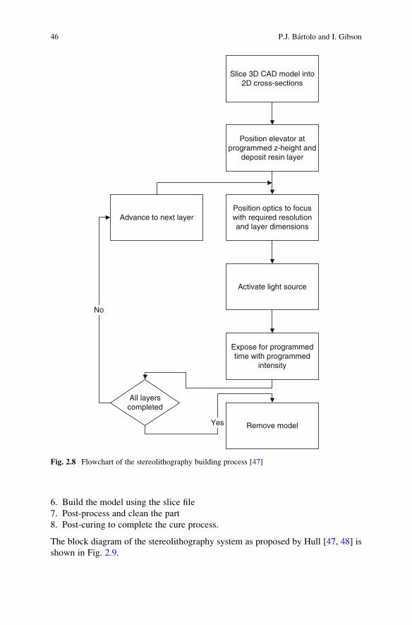
6. Build the model using the slice file
7. Post-process and clean the part
8. Post-curing to complete the cure process.
The block diagram of the stereolithography system as proposed by Hull [47, 48] is
shown in Fig. 2.9.
Slice 3D CAD model into2D cross-sections
Position elevator atprogrammed z-height and
deposit resin layer
Position optics to focuswith required resolutionand layer dimensions
Activate light source
Expose for programmedtime with programmed
intensity
Remove model
All layerscompleted
Yes
Advance to next layer
No
Fig. 2.8 Flowchart of the stereolithography building process [47]
46 P.J. Bartolo and I. Gibson

Hull also proposed other stereolithographic strategies as shown in Fig. 2.10.
In this system the physical object is pulled up from the liquid resin, rather than
down and further into the liquid photopolymeric system [47]. The radiation passes
through a UV transparent window.
In order to minimize the amount photopolymerisable material required for the
fabrication process, Murphy et al. [52] proposed a stereolithographic method and
apparatus in which a membrane separates two liquid phases. The system (Fig. 2.11)
Fig. 2.9 The block diagram of the stereolithography system [48]
2 History of Stereolithographic Processes 47

comprises a nonpolymerisable fluid phase, an impermeable movable membrane
positioned on top of the fluid phase, a photopolymerisable liquid resin positioned on
top of the membrane and a radiation source positioned above the polymerisable
material [52].
Fig. 2.10 The ascending fabrication platform proposed by [47]
Fig. 2.11 Stereolithographic apparatus with membrane [52]
48 P.J. Bartolo and I. Gibson

Almquist and Smalley [53] proposed the concept of thermal stereolithography
that uses a solid material, instead of a liquid one, which is flowable when subjected
to light.
Marutani [54, 55] has proposed a new stereolithographic system that poly-
merises a liquid resin inside the vat rather than at the surface. In this system a
UV laser beam penetrates through a pipe into the vat containing the liquid resin and
solidifies it, thereby eliminating the need for successive layer deposition as in
conventional stereolithography.
An important evolution step in the stereolithography domain is the so-called
color stereolithography [56]. This process uses a clear liquid resin containing
additives that color upon exposure to high doses of UV radiation. Through this
process, each layer is cured in the usual way, using a dose of UV radiation sufficient
for curing but not for coloring. When the “writing” process of each layer is
completed, the laser rescans the area required to be colored at a lower speed,
delivering in this way a much higher dose of UV radiation. This provides
a means to highlight features in a model and, since the uncoloured stereolithogra-
phy resins are transparent, to show features that may be embedded inside the
encompassing solid object. A more laborious coloring strategy was proposed by
Im et al. [57] (Fig. 2.12).
Fig. 2.12 Colouring stereolithography [57]
2 History of Stereolithographic Processes 49

In order to eliminate the need of support structures, Murakami [58, 59] proposed
a stereolithographic approach for fabricating solid (cured) objects from solid (non-
cured) photopolymeric resin (Fig. 2.13). First, a liquid resin is supplied to form a new
layer, cooled to the gel state (between �50 and �10�C), and then selectively photo-
polymerised. The final object is revealed by heating the gel resin block [58–60].
Other important inventions are listed on Table 2.1.
2.4.1.2 Photomask Systems
Pomerantz [61, 62] proposed a photomask system to produce 3D models (Fig. 2.14).
The steps of his technique, currently known as Solid Ground Curing (SGC), are:
deposit a thin layer of polymer; illuminate the polymer through a xerographically
produced mask having geometry of a single cross section; removal by suction of the
uncured material; fill the areas vacated by the uncured material with water or wax;
cure or freeze the rest of the layer; grind the surface to establish a uniform layer; repeat
the earlier steps until the model is complete.
Fudim [63, 64] developed a technique similar to the Pomerantz method.
His technique [63, 64] involves the illumination of a photosensitive polymer, with
UV radiation through masks and a piece of flat material transparent to the radiation
that remains in contact with the liquid layer being formed. The method is simpler
than the SGC technique, but requires an operator to create and manually position
each mask.
Photomasking systems generally require the generation of many masks, and
precise mask alignments. One solution to this problem is to use a liquid crystal
Fig. 2.13 Stereolithography using a solgel transformable photopolymer [60]
50 P.J. Bartolo and I. Gibson

Fig. 2.14 The photo-fabrication system proposed by Pomerantz [61]
Table 2.1 Other relevant laser lithography patents
Inventors Topic Patent
Hull et al. Discloses various removable support structures for
stereolithography
US Patent 4999143
Modrek et al. Presents techniques for post processing objects
produced by stereolithography
US Patent 5076974
Spence et al. Proposes the use of multiple wavelengths in the
exposure of a stereolithographic medium
US Patent 5182056
Hull et al. Discloses a program called Slice and various techniques
for converting 3D object data into data descriptive
of cross-sections
US Patent 5184307
Allison et al. Proposes various build/exposure styles and various
techniques for reducing object distortion
US Patent 5256340
Almquist et al. Proposes various recoating techniques for
stereolithography. Presents techniques such as
(1) an inkjet dispensing device, (2) a fling recoater,
(3) a vacuum applicator, (4) a stream recoater,
(5) a counter-rotating roller recoater, and
(6) a technique for deriving sweep extents
US Patent 08/790005
Partanen et al. Proposes the application of solid-state lasers to
stereolithography
US Patent 08/792347
Partanen et al. Discloses the use of a pulsed radiation source in
stereolithography
US Patent 08/847855
Bloomstein et al. Presents a stereolithographic patterning system with
variable size exposure areas
US Patent 633234
2 History of Stereolithographic Processes 51

display (LCD) or a digital processing projection system as a reconfigurable mask [16].
Through this process, the CADmodel is converted to a grayscale contourmap, and the
LCD mask modulates the light intensity distribution according to the gray-scale
contour map of the model. However, due to the large pixel size and very low
transmission in UV, the device’s resolution is limited and contrast is poor. Therefore,
several stereolithographic systems using a Digital Micromirror Device as a dynamic
mask have been proposed (Fig. 2.15) [65, 66].
Recently Murakami [60] from the University of Tokyo, Japan, proposed a new
stereolithographic system involving the separate use of a liquid photo-initiator and a
photopolymer without photoinitiator. In this process (Fig. 2.16), the resin without
photoinitiator is supplied as a layer, and then amask pattern is drawn onto the surface
with photoinitiator by inkjet printing. When the surface is exposed to UV light, only
the pattern drawn with the photoinitiator, which acts as a positive mask, is cured.
Fig. 2.15 Dynamic mask projection stereo micro lithography proposed by Zhang [65]
52 P.J. Bartolo and I. Gibson

References
1. J. Wilson, J.F.B. Hawkes. Lasers, principles and applications. Prentice Hall, New York, 1987
2. I. Gibson, D.W. Rosen, B. Stucker. Additive manufacturing technologies: rapid prototyping todirect digital manufacturing. Springer, New York, 2009
3. C.K. Chua, K.F. Leong, C.S. Lim. Rapid prototyping – principles and applications. World
Scientific Publishing, Singapore, 2003
4. I. Gibson. Rapid prototyping from product development to medicine, Virtual and PhysicalPrototyping. 1, 31–42, 2006
Fig. 2.16 Stereolithography
process using positive direct-
mask exposure [60]
2 History of Stereolithographic Processes 53

5. B. Bidanda, P.J. Bartolo. Virtual prototyping & bio-manufacturing in medical applications.Springer, New York, 2008
6. S. Kumas, J.P. Kruth. Composites by rapid prototyping technology. Materials and Design,31, 850–856, 2010
7. J.P. Kruth, G. Levy, T.H.C. Childs. Consolidation phenomena in laser and powder-bed based
layered manufacturing. CIRP Annals – Manufacturing Technology, 35, 730–759, 20078. P.J. Bartolo, J. Gaspar. Metal filled resin for stereolithography metal part. CIRP Annals –
Manufacturing Technology, 57, 235–238, 20089. J. Cryzewski, P. Burzynski, K. Gawel, J. Meisner. Rapid prototyping of electrically conduc-
tive components using 3D printing technology. Journal of Materials Processing Technology,209, 5281–5285, 2009
10. T. Grimm. User’s guide to rapid prototyping. Society of Manufacturing Engineers, Dearborn,
2004
11. N. Tolochko, S. Mozzharov, T. Laoui, L. Froyen. Selective laser sintering of single- and two-
component metal powders. Rapid Prototyping Journal, 9, 68–78, 200312. P.J. Bartolo, G. Mitchell. Stereo-thermal-lithography: a new principle for rapid prototyping.
Rapid Prototyping Journal, 9, 150–156, 200313. G.N. Levy, R. Schindel, J.-P. Kruth. Rapid manufacturing and rapid tooling with layer
manufacturing (LM) technologies, state of the art and future perspectives. CIRP Annals –Manufacturing Technology, 52(2), 589–609, 2003
14. D.L. Bourell, J.B. Beaman, M.C. Leu, D.W. Rosen. A brief history of additive manufacturing
and the 2009 roadmap for additive manufacturing: looking back and looking ahead.US-TurkeyWorkshop on Rapid Technologies, 2009
15. J. Zhao, R. Xia, W. Liu, H. Wang. A computing method for accurate slice contours based on
na STL model. Virtual and Physical Prototyping, 4, 29–37, 200916. P.J. Bartolo. Optical approaches to macroscopic and microscopic engineering, PhD Thesis,
University of Reading, UK, 2001
17. M. Greulich, M. Greul, T. Pintat. Fast functional prototypes via multiphase jet solidification.
Rapid Prototyping Journal, 1, 20–25, 199518. N.P. Karapatis, J.P.S. Van Griethuysen, R. Glardon. Direct rapid tooling. Rapid Prototyping
Journal, 4, 77–78, 199819. G.A. Hindson, A.K. Kochhar, P. Cook. Procedures for effective implementation of simulta-
neous engineering in small to medium enterprises. Proceedings of the Institution of Mechani-cal Engineers, Part B: Journal of Engineering Manufacture, 212, 251–258, 1998
20. P. Krouwel, in Research in design thinking, Edited by N. Cross, C. Dorst and N. Rootenbury,
Delft University Press, Delft, 1992
21. D. Kochan, C.K. Chua. State-of-the-art and future trends in advanced rapid prototyping and
manufacturing. International Journal of Information Technology, 1, 173–184, 199522. S. Azernikov, A. Fischer. Emerging non-contact 3D measurement technologies for shape
retrieval and processing. Virtual and Physical Prototyping, 3, 85–91, 200823. S. Rianmora, P. Koomsap, D.P.V. Hai. Selective data acquisition for direct integration of
reverse engineering and rapid prototyping. Virtual and Physical Prototyping, 4, 227–239,2009
24. F. Laroche, A. Bernard,M. Cotte. Advanced industrial archaeology: a new reverse-engineering
process for contextualising and digitising ancient technical objects. Virtual and PhysicalPrototyping, 3, 105–122, 2008
25. N.M.F. Alves, P.J.S. Bartolo. Automatic 3D shape recovery for rapid prototyping. Virtual andPhysical Prototyping, 3, 123–137, 2008
26. W. De Vries. Analysis of material removal processes. Springer-Verlag, New York, 1992
27. S. Kalpakjian, S.R. Schmid. Manufacturing engineering and tooling. Prentice Hall,
New Jersey, 2000
28. E.M. Malstrom. Manufacturing cost estimating. Marcel Dekker, New York, 1981
54 P.J. Bartolo and I. Gibson
29. I. Madrazo, C. Zamorano, E. Magallon, T. Valenzuela, A. Ibarra, H. Salgado-Ceballos,
I. Grijalva, R.E. Franco-Bourland, G. Guızar-Sahagun. Stereolithography in spine pathology:
a 2-case report. Surgical Neurology, 72, 272–275, 200930. V. Dedoussis, V. Canellidis, K. Mathioudakis. Aerodynamic experimental investigation using
stereolithography fabricated test models: the case of a linear compressor blading cascade.
Virtual and Physical Prototyping, 3, 151–157, 200831. V. Dedoussis, J. Giannatsis. Stereolithography assisted redesign and optimisation of a dish-
washer spraying arm. Rapid Prototyping Journal, 10, 255–260, 200432. J. Giannatsis, V. Dedoussis, D. Karalekas. Architectural scale modelling using stereolitho-
graphy. Rapid Prototyping Journal, 8, 200–207, 200233. P.J. Bartolo, C.K. Chua, H.A. Almeida, S.M. Chou, A.S.C. Lim. Biomanufacturing for tissue
engineering: present and future trends. Virtual and Physical Prototyping, 4, 203–216, 200934. M. Burns. Automated fabrication – improving productivity in manufacturing. Prentice Hall,
New Jersey, 1993
35. Y. Morita, T. Noikura, R. Petzold, M. Blank, W. Kalender, S. Hiura, A. Okubo, K. Sugihara,
T. Kamiinaba, Y. Izumi. Rapid prototyping for dentistry in Japan. Proceedings of the eighthinternational conference on rapid prototyping, Edited by T. Nakagawa, Y. Marutani,
M. Imamura, M. Agarwala, A. Lightman, D. Klosterman, and R.P. Chartoff, University of
Dayton, 2000
36. C.C. An, R.H. Chen. The experimental study on the defects occurrence of SL mold in injection
molding. Journal of Materials Processing Technology, 201, 706–709, 200837. S. Rahmati, P. Dickens. Rapid tooling analysis of stereolithography injection mould tooling.
International Journal of Machine Tools & Manufacture, 47, 740–747, 200738. G. Kakarala, A.D. Toms, J.H. Kuiper. Stereolithography models for biomechanical testing.
The Knee, 13, 451–454, 200639. H. Gernsheim, A. Gernsheim. The history of photography: from the camera obscura to the
beginning of the modern era. McGraw Hill, New York, 1969
40. W.K. Swainson. Method, medium and apparatus for producing three-dimensional figureproduct, US Patent 4041476, 1977
41. R.E. Schwerzel, V.E. Wood, V.D. McGinniss, C.M. Verber. 3D photochemical machining
with lasers, Applications of lasers to industrial Chemistry. SPIE, 458, 90–97, 198442. W.K. Swainson, S.D. Kramer. Three-dimensional pattern making methods, US Patent
4333165, 1982
43. W.K. Swainson, S.D. Kramer. Three-dimensional patterned media, US Patent 4466080, 1984
44. W.K. Swainson, S.D. Kramer. Method and media for accessing data in three dimensions, USPatent 4471470, 1984
45. H. Kodama. Automatic method for fabricating a three-dimensional plastic model with photo-
hardening polymer. Review of Scientific Instruments, 52, 1770–1773, 198146. A.J. Herbert. Solid object generation. Journal of Applied Photographic Engineering, 8,
185–188, 1982
47. C.W. Hull. Apparatus for production of three-dimensional objects by stereolithography, USPatent 4575330, 1986
48. C.W. Hull, S.T. Spence, D.J. Albert, D.R. Smalley, R.A. Harlow, P. Steinbaugh, H.L. Tarnoff,
H.D. Nguyen, C.W. Lewis, T.J. Vorgitch, D.Z. Remba.Method and apparatus for productionof three-dimensional objects by stereolithography, US Patent 5059359, 1991
49. C.W. Hull, S.T. Spence, D.J. Albert, D.R. Smalley, R.A. Harlow, P. Stinebaugh, H.L. Tarnoff,
H.D. Nguyen, C.W. Lewis, T.J. Vorgitch, D.Z. Remba.Method and apparatus for productionof high resolution three-dimensional objects by stereolithography, US Patent 5184307, 1993
50. J.C. Andre, M. Cabrera, J.Y. Jezequel, A. Mehaute. French Pat. 2583333, 1985
51. J.C. Andre, A. Mehaute, O. Witthe. Dispositif pour realiser un module de piece industrielle,French Pat. 8411241, 1984
52. E.J. Murphy, J.J. Krajewski, R.E. Ansel. Stereolithographic method and apparatus in which amembrane separates phases, US Patent 5011635, 1991
2 History of Stereolithographic Processes 55

53. T.A. Almquist, D.S. Smalley. Thermal stereolithography, US Patent 5672312, 1997
54. Y. Marutani, T. Kamitani. 3-Dimensional exposure using an air bubble in the resin. Proceedingsof the seventh international conference on rapid prototyping, Edited by A.J. Lightman and
R.P. Chartoff, University of Dayton, 1997, 213
55. J.-P. Kruth,M.C. Leu, T. Nakagawa. Progress in additivemanufacturing and rapid prototyping.
CIRP Annals – Manufacturing Technology, 47, 525–549, 199856. B. Swaelens, W. Vancraen. Laser photopolymerisation models based on medical imaging:
a development improving the accuracy of surgery. Proceedings of the seventh internationalconference on rapid prototyping, Edited by A.J. Lightman and R.P. Chartoff, University of
Dayton, 1997, 250
57. Y.G. Im, S.I. Chung, J.H. Son, Y.D. Jung, J.G. Jo, H.D. Jeong. Functional prototype develop-
ment: inner visible multi-color prototype fabrication process using stereo lithography. Journalof Materials Processing Technology, 130–131, 372–377, 2002
58. T. Murakami, A. Kamimura, N. Nakajima. Refrigerative stereolithography using sol-gel
transformable photopolymer resin and direct masking. Solid Freeform and AdditiveManufacturing – 2000, Edited by S.C. Danforth, D. Dimos, and F. Pritz, Materials Research
Society, Warrendale, 2000
59. T. Murakami, A. Kamimura, N. Nakajima. Refrigerative stereolithography using direct
masking. Proceedings of the eigth International Conference on Rapid Prototyping, JapanSociety of Die and Molds Technology, Tokyo, Japan, 2000
60. T. Murakami, T. Yada, G. Kobayashi. Positive direct-mask stereolithography with multiple-
layer exposure: layered fabrication with stair step reduction. Virtual and Physical Prototyping,1, 73–81, 2006
61. I. Pomerantz, J. Cohen-Sabban, A. Bieber, J. Kamir, M. Katz, M. Nagler. Three dimensionalmodelling apparatus, US Patent 4961154, 1990
62. I. Pomerantz, S. Gilad, Y. Dollberg, B. Ben-Ezra, Y. Sheinman, G. Barequet, M. Katz. Threedimensional modelling apparatus, US Patent 5519816, 1996
63. E.V. Fudim. Method and apparatus for production of three-dimensional objects by photo-solidification, US Patent 4801477, 1989
64. E.V. Fudim. Method and apparatus for production of three-dimensional objects by photo-solidification, US Patent 4752498, 1988
65. X. Zhang. Dynamic mask projection stereo micro lithography, US Patent 2005/0259785 A1,
2005
66. C. Sun, N. Fang, D.M. Wu, X. Zhang. Projection micro-stereolithography using digital micro-
mirror dynamic mask. Sensors and Actuators A, 121, 113–120, 2005
56 P.J. Bartolo and I. Gibson