Embed Size (px)
Citation preview
Background on Creating Images for CrystalEyes® and SimulEyes®
T E R E O R A P H I C SS G
DEVELOPERS' HANDBOOK
1997 StereoGraphics Corporation
StereoGraphics Developers’ HandbookTable of Contents
CHAPTER 1 1
Depth Cues 1Introduction 1Monocular Cues 3Summing Up 4References 5
CHAPTER 2 7
Perceiving Stereoscopic Images 7Retinal Disparity 7Parallax 8Parallax Classifications 9Interaxial Seperation 10Congruent Nature of the Fields 10Accommodation/Convergence Relationship 11Control of Parallax 12Crosstalk 12Curing the Problems 13Summary 13References 13
CHAPTER 3 15
Composition 15Accommodation/Convergence 16Screen Surround 17Orthostereoscopy 18ZPS and HIT 20Viewer-Space Effects 21Viewer Distance 22Software Tips 22Proposed Standard 23Summary 24References 26
CHAPTER 4 27
Stereo-Vision Formats 27What’s a Format? 27Interlace Stereo 28Above-and-Below Format 28Stereo-Ready Computers 30Side-by-Side 31White-Line-Code 31Summing Up 33
CHAPTER 5 35
Parallalel Lens Axes 35The Camera Model 36The Parallax Factor 37Windows and Cursors 39References 40
CHAPTER 6 41
Creating Stereoscopic Software 41
CREATING STEREOSCOPIC PAIRS 42Perspective Projections 42Stereo Perspective Projections 43Parallax: Too Much of a Good Thing? 44Putting the Eyes Where They Belong 45Interacting with the User 49
THE ABOVE-BELOW FORMAT 49Initialization and Interface Issues for Above-Below Stereo 51
THE SIMULEYES VR STEREOSCOPIC FORMAT 52SimulEyes VR White Line Code 52Initialization and Interface Issues for SimulEyes VR Stereo 52Pseudoscopic Images 53The Page-Swap Alternative 54
GLOSSARY 55
INDEX 59
1
The StereoGraphics Developers' Handbook : 1. Depth Cues
C H A P T E R 1
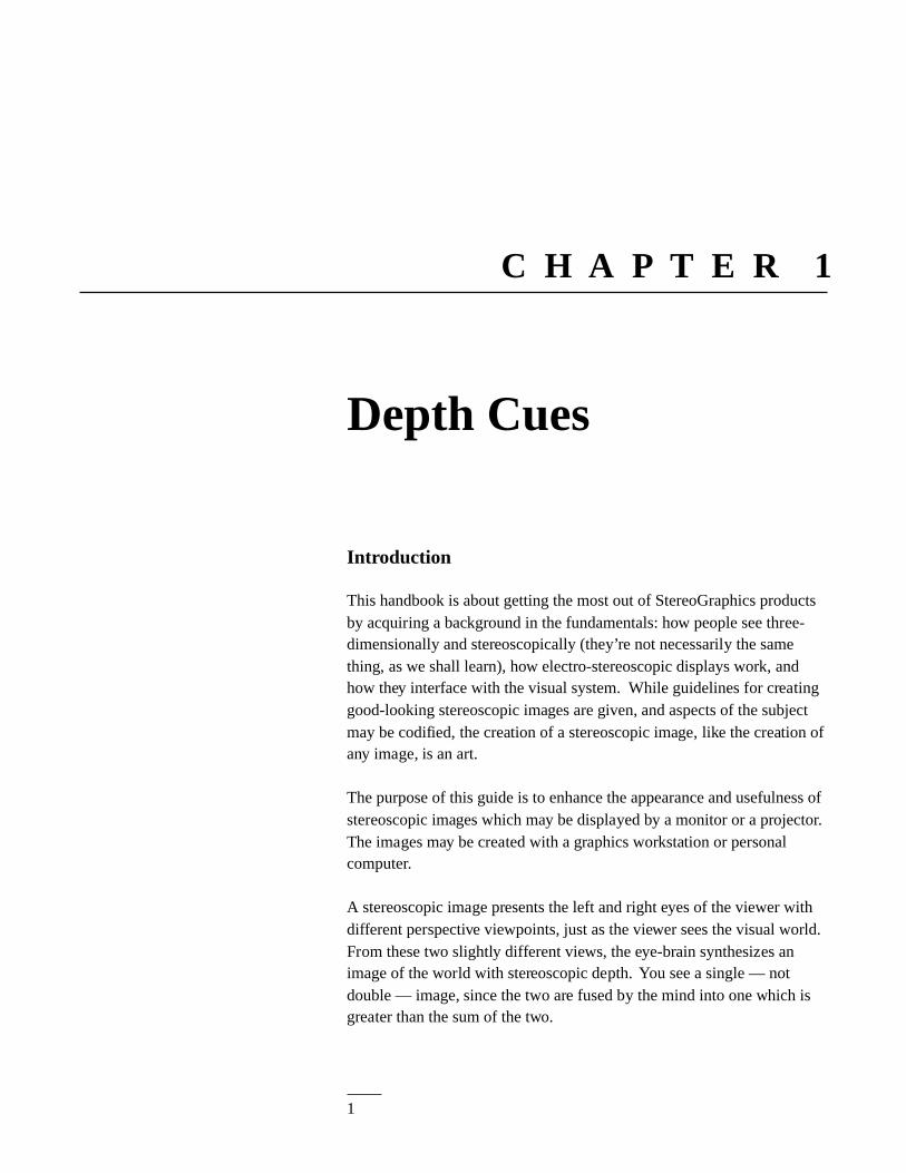
Introduction
This handbook is about getting the most out of StereoGraphics productsby acquiring a background in the fundamentals: how people see three-dimensionally and stereoscopically (they’re not necessarily the samething, as we shall learn), how electro-stereoscopic displays work, andhow they interface with the visual system. While guidelines for creatinggood-looking stereoscopic images are given, and aspects of the subjectmay be codified, the creation of a stereoscopic image, like the creation ofany image, is an art.
The purpose of this guide is to enhance the appearance and usefulness ofstereoscopic images which may be displayed by a monitor or a projector.The images may be created with a graphics workstation or personalcomputer.
A stereoscopic image presents the left and right eyes of the viewer withdifferent perspective viewpoints, just as the viewer sees the visual world.From these two slightly different views, the eye-brain synthesizes animage of the world with stereoscopic depth. You see a single — notdouble — image, since the two are fused by the mind into one which isgreater than the sum of the two.
Depth Cues
2
The StereoGraphics Developers' Handbook : 1. Depth Cues
Stereo
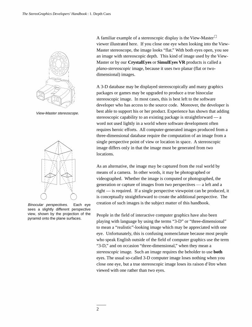
View-Master stereoscope.
Binocular perspectives. Each eye sees a slightly different perspective view, shown by the projection of the pyramid onto the plane surfaces.
A familiar example of a stereoscopic display is the View-Master
viewer illustrated here. If you close one eye when looking into the View-Master stereoscope, the image looks “flat.” With both eyes open, you seean image with stereoscopic depth. This kind of image used by the View-Master or by our CrystalEyes or SimulEyes VR products is called aplano-stereoscopic image, because it uses two planar (flat or two-dimensional) images.
A 3-D database may be displayed stereoscopically and many graphicspackages or games may be upgraded to produce a true binocularstereoscopic image. In most cases, this is best left to the softwaredeveloper who has access to the source code. Moreover, the developer isbest able to support his or her product. Experience has shown that addingstereoscopic capability to an existing package is straightforward — aword not used lightly in a world where software development oftenrequires heroic efforts. All computer-generated images produced from athree-dimensional database require the computation of an image from asingle perspective point of view or location in space. A stereoscopicimage differs only in that the image must be generated from twolocations.
As an alternative, the image may be captured from the real world bymeans of a camera. In other words, it may be photographed orvideographed. Whether the image is computed or photographed, thegeneration or capture of images from two perspectives — a left and aright — is required. If a single perspective viewpoint can be produced, itis conceptually straightforward to create the additional perspective. Thecreation of such images is the subject matter of this handbook.
People in the field of interactive computer graphics have also beenplaying with language by using the terms “3-D” or “three-dimensional”to mean a “realistic”-looking image which may be appreciated with oneeye. Unfortunately, this is confusing nomenclature because most peoplewho speak English outside of the field of computer graphics use the term“3-D,” and on occasion “three-dimensional,” when they mean astereoscopic image. Such an image requires the beholder to use botheyes. The usual so-called 3-D computer image loses nothing when youclose one eye, but a true stereoscopic image loses its raison d’être whenviewed with one rather than two eyes.
3
The StereoGraphics Developers' Handbook : 1. Depth Cues
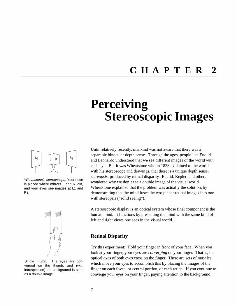
Aerial perspective.
Textural gradient.
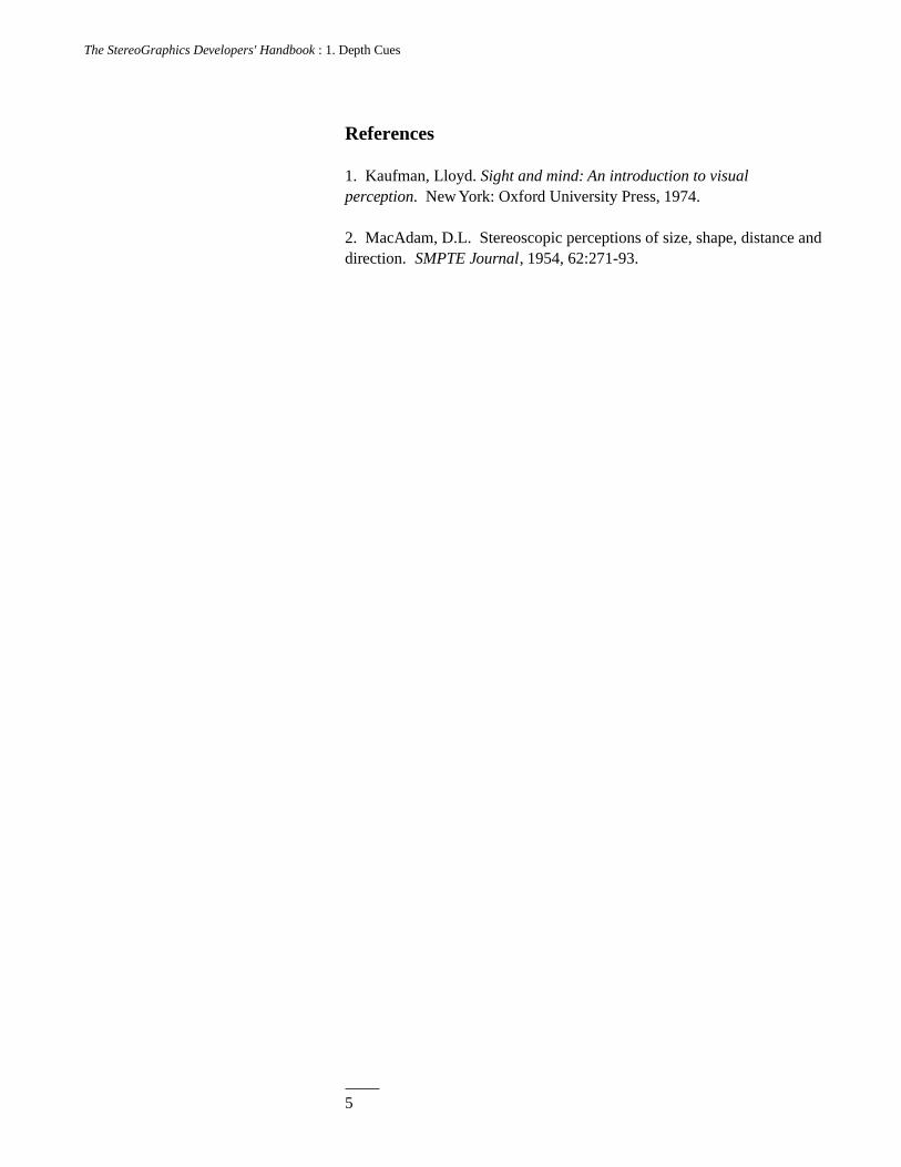
Interposition.
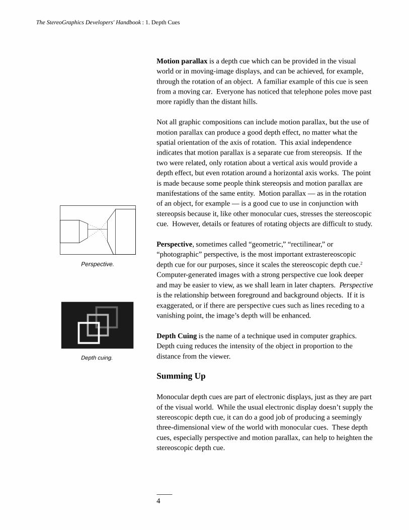
Relative size.
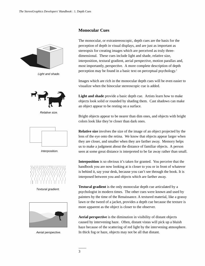
Light and shade.
Monocular Cues
The monocular, or extrastereoscopic, depth cues are the basis for theperception of depth in visual displays, and are just as important asstereopsis for creating images which are perceived as truly three-dimensional. These cues include light and shade, relative size,interposition, textural gradient, aerial perspective, motion parallax and,most importantly, perspective. A more complete description of depthperception may be found in a basic text on perceptual psychology.1
Images which are rich in the monocular depth cues will be even easier tovisualize when the binocular stereoscopic cue is added.
Light and shade provide a basic depth cue. Artists learn how to makeobjects look solid or rounded by shading them. Cast shadows can makean object appear to be resting on a surface.
Bright objects appear to be nearer than dim ones, and objects with brightcolors look like they’re closer than dark ones.
Relative size involves the size of the image of an object projected by thelens of the eye onto the retina. We know that objects appear larger whenthey are closer, and smaller when they are farther away. Memory helpsus to make a judgment about the distance of familiar objects. A personseen at some great distance is interpreted to be far away rather than small.
Interposition is so obvious it’s taken for granted. You perceive that thehandbook you are now looking at is closer to you or in front of whateveris behind it, say your desk, because you can’t see through the book. It isinterposed between you and objects which are farther away.
Textural gradient is the only monocular depth cue articulated by apsychologist in modern times. The other cues were known and used bypainters by the time of the Renaissance. A textured material, like a grassylawn or the tweed of a jacket, provides a depth cue because the texture ismore apparent as the object is closer to the observer.
Aerial perspective is the diminution in visibility of distant objectscaused by intervening haze. Often, distant vistas will pick up a bluishhaze because of the scattering of red light by the intervening atmosphere.In thick fog or haze, objects may not be all that distant.
4
The StereoGraphics Developers' Handbook : 1. Depth Cues
Motion parallax is a depth cue which can be provided in the visualworld or in moving-image displays, and can be achieved, for example,
through the rotation of an object. A familiar example of this cue is seenfrom a moving car. Everyone has noticed that telephone poles move pastmore rapidly than the distant hills.
Not all graphic compositions can include motion parallax, but the use of
motion parallax can produce a good depth effect, no matter what thespatial orientation of the axis of rotation. This axial independenceindicates that motion parallax is a separate cue from stereopsis. If the
two were related, only rotation about a vertical axis would provide adepth effect, but even rotation around a horizontal axis works. The point
is made because some people think stereopsis and motion parallax aremanifestations of the same entity. Motion parallax — as in the rotationof an object, for example — is a good cue to use in conjunction with
stereopsis because it, like other monocular cues, stresses the stereoscopiccue. However, details or features of rotating objects are difficult to study.
Perspective, sometimes called “geometric,” “rectilinear,” or“photographic” perspective, is the most important extrastereoscopic
depth cue for our purposes, since it scales the stereoscopic depth cue.2
Computer-generated images with a strong perspective cue look deeper
and may be easier to view, as we shall learn in later chapters. Perspectiveis the relationship between foreground and background objects. If it is
exaggerated, or if there are perspective cues such as lines receding to avanishing point, the image’s depth will be enhanced.
Depth Cuing is the name of a technique used in computer graphics.Depth cuing reduces the intensity of the object in proportion to the
distance from the viewer.
Summing Up
Monocular depth cues are part of electronic displays, just as they are part
of the visual world. While the usual electronic display doesn’t supply thestereoscopic depth cue, it can do a good job of producing a seeminglythree-dimensional view of the world with monocular cues. These depth
cues, especially perspective and motion parallax, can help to heighten thestereoscopic depth cue.
Depth cuing.
Perspective.
5
The StereoGraphics Developers' Handbook : 1. Depth Cues
References
1. Kaufman, Lloyd. Sight and mind: An introduction to visualperception. New York: Oxford University Press, 1974.
2. MacAdam, D.L. Stereoscopic perceptions of size, shape, distance anddirection. SMPTE Journal, 1954, 62:271-93.
7
The StereoGraphics Developers' Handbook : 2. Perceiving Stereoscopic Images
C H A P T E R 2
Wheatstone's stereoscope. Your nose is placed where mirrors L and R join, and your eyes see images at L1 and R1.
L RL R1 1
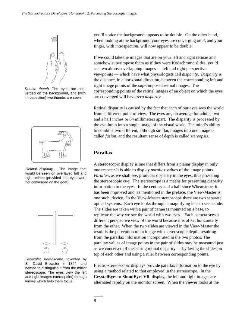
Single thumb. The eyes are con-verged on the thumb, and (with introspection) the background is seen as a double image.
Until relatively recently, mankind was not aware that there was aseparable binocular depth sense. Through the ages, people like Euclidand Leonardo understood that we see different images of the world witheach eye. But it was Wheatstone who in 1838 explained to the world,with his stereoscope and drawings, that there is a unique depth sense,stereopsis, produced by retinal disparity. Euclid, Kepler, and otherswondered why we don’t see a double image of the visual world.Wheatstone explained that the problem was actually the solution, bydemonstrating that the mind fuses the two planar retinal images into onewith stereopsis (“solid seeing”).1
A stereoscopic display is an optical system whose final component is thehuman mind. It functions by presenting the mind with the same kind ofleft and right views one sees in the visual world.
Retinal Disparity
Try this experiment: Hold your finger in front of your face. When youlook at your finger, your eyes are converging on your finger. That is, theoptical axes of both eyes cross on the finger. There are sets of muscleswhich move your eyes to accomplish this by placing the images of thefinger on each fovea, or central portion, of each retina. If you continue toconverge your eyes on your finger, paying attention to the background,
PerceivingStereoscopic Images
8
The StereoGraphics Developers' Handbook : 2. Perceiving Stereoscopic Images
you’ll notice the background appears to be double. On the other hand,when looking at the background your eyes are converging on it, and yourfinger, with introspection, will now appear to be double.
If we could take the images that are on your left and right retinae andsomehow superimpose them as if they were Kodachrome slides, you’dsee two almost-overlapping images — left and right perspectiveviewpoints — which have what physiologists call disparity. Disparity isthe distance, in a horizontal direction, between the corresponding left andright image points of the superimposed retinal images. Thecorresponding points of the retinal images of an object on which the eyesare converged will have zero disparity.
Retinal disparity is caused by the fact that each of our eyes sees the worldfrom a different point of view. The eyes are, on average for adults, twoand a half inches or 64 millimeters apart. The disparity is processed bythe eye-brain into a single image of the visual world. The mind’s abilityto combine two different, although similar, images into one image iscalled fusion, and the resultant sense of depth is called stereopsis.
Parallax
A stereoscopic display is one that differs from a planar display in onlyone respect: It is able to display parallax values of the image points.Parallax, as we shall see, produces disparity in the eyes, thus providingthe stereoscopic cue. The stereoscope is a means for presenting disparityinformation to the eyes. In the century and a half since Wheatstone, ithas been improved and, as mentioned in the preface, the View-Master isone such device. In the View-Master stereoscope there are two separateoptical systems. Each eye looks through a magnifying lens to see a slide.The slides are taken with a pair of cameras mounted on a base, toreplicate the way we see the world with two eyes. Each camera sees adifferent perspective view of the world because it is offset horizontallyfrom the other. When the two slides are viewed in the View-Master theresult is the perception of an image with stereoscopic depth, resultingfrom the parallax information incorporated in the two photos. Theparallax values of image points in the pair of slides may be measured justas we conceived of measuring retinal disparity — by laying the slides ontop of each other and using a ruler between corresponding points.
Electro-stereoscopic displays provide parallax information to the eye byusing a method related to that employed in the stereoscope. In theCrystalEyes or SimulEyes VR display, the left and right images arealternated rapidly on the monitor screen. When the viewer looks at the
Double thumb. The eyes are con-verged on the background, and (with introspection) two thumbs are seen.
Retinal disparity. The image that would be seen on overlayed left and right retinae (provided the eyes were not converged on the goat).
Lenticular stereoscope. Invented by Sir David Brewster in 1844, and named to distinguish it from the mirror stereoscope. The eyes view the left and right images (stereopairs) through lenses which help them focus.
9
The StereoGraphics Developers' Handbook : 2. Perceiving Stereoscopic Images
screen through shuttering eyewear, each shutter is synchronized toocclude the unwanted image and transmit the wanted image. Thus eacheye sees only its appropriate perspective view. The left eye sees only theleft view, and the right eye only the right view.
If the images (the term “fields” is often used for video and computergraphics) are refreshed (changed or written) fast enough (often at twicethe rate of the planar display), the result is a flickerless stereoscopicimage. This kind of a display is called a field-sequential stereoscopicdisplay. It was this author’s pleasure to build, patent, and commerciallyexploit the first flickerless field-sequential electro-stereoscopic display,which has become the basis for virtually every stereoscopic computergraphics product.2
When you observe an electro-stereoscopic monitor image without oureyewear, it looks like there are two images overlayed and superimposed.The refresh rate is so high that you can’t see any flicker, and it looks likethe images are double-exposed. The distance between left and rightcorresponding image points (sometimes also called “homologous” or“conjugate” points) is parallax, and may be measured in inches ormillimeters.
Parallax and disparity are similar entities. Parallax is measured at thedisplay screen, and disparity is measured at the retinae. When wearingour eyewear, parallax becomes retinal disparity. It is parallax whichproduces retinal disparity, and disparity in turn produces stereopsis.Parallax may also be given in terms of angular measure, which relates itto disparity by taking into account the viewer’s distance from the displayscreen.
Because parallax is the entity which produces the stereoscopic depthsensation, it’s important to study it. Below is a classification of the kindsof parallax one may encounter when viewing a display screen.
Parallax Classifications
Four basic types of parallax are shown in the drawings. In the first case,zero parallax, the homologous image points of the two images exactlycorrespond or lie on top of each other. When the eyes of the observer,spaced apart at distance t (the interpupillary or interocular distance, onaverage two and a half inches), are looking at the display screen andobserving images with zero parallax, the eyes are converged at the planeof the screen. In other words, the optical axes of the eyes cross at theplane of the screen. When image points have zero parallax, they are saidto have zero parallax setting (ZPS).Zero parallax.
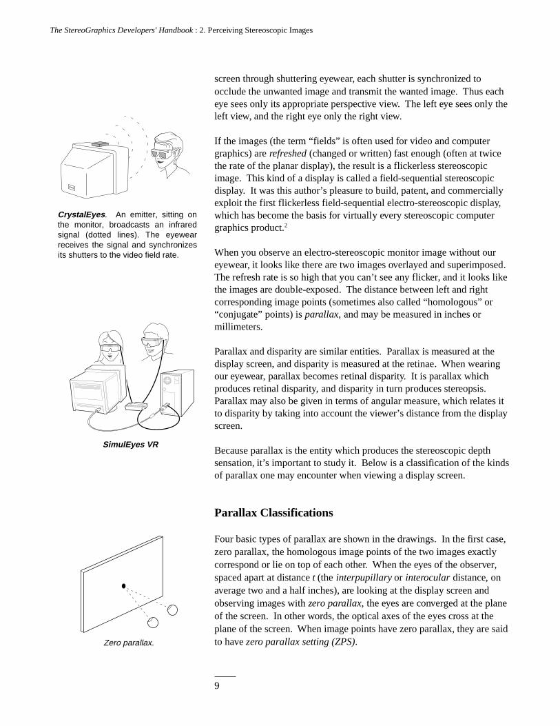
CrystalEyes. An emitter, sitting on the monitor, broadcasts an infrared signal (dotted lines). The eyewear receives the signal and synchronizes its shutters to the video field rate.
SimulEyes VR
10
The StereoGraphics Developers' Handbook : 2. Perceiving Stereoscopic Images
tc
Interaxial separation, t . c
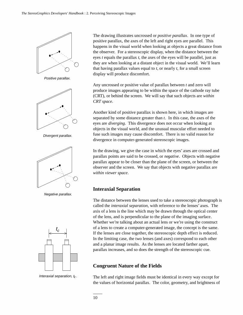
The drawing illustrates uncrossed or positive parallax. In one type ofpositive parallax, the axes of the left and right eyes are parallel. Thishappens in the visual world when looking at objects a great distance fromthe observer. For a stereoscopic display, when the distance between theeyes t equals the parallax t, the axes of the eyes will be parallel, just asthey are when looking at a distant object in the visual world. We’ll learnthat having parallax values equal to t, or nearly t, for a small screendisplay will produce discomfort.
Any uncrossed or positive value of parallax between t and zero willproduce images appearing to be within the space of the cathode ray tube(CRT), or behind the screen. We will say that such objects are withinCRT space.
Another kind of positive parallax is shown here, in which images areseparated by some distance greater than t. In this case, the axes of theeyes are diverging. This divergence does not occur when looking atobjects in the visual world, and the unusual muscular effort needed tofuse such images may cause discomfort. There is no valid reason fordivergence in computer-generated stereoscopic images.
In the drawing, we give the case in which the eyes’ axes are crossed andparallax points are said to be crossed, or negative. Objects with negativeparallax appear to be closer than the plane of the screen, or between theobserver and the screen. We say that objects with negative parallax arewithin viewer space.
Interaxial Separation
The distance between the lenses used to take a stereoscopic photograph iscalled the interaxial separation, with reference to the lenses’ axes. Theaxis of a lens is the line which may be drawn through the optical centerof the lens, and is perpendicular to the plane of the imaging surface.Whether we’re talking about an actual lens or we’re using the constructof a lens to create a computer-generated image, the concept is the same.If the lenses are close together, the stereoscopic depth effect is reduced.In the limiting case, the two lenses (and axes) correspond to each otherand a planar image results. As the lenses are located farther apart,parallax increases, and so does the strength of the stereoscopic cue.
Congruent Nature of the Fields
The left and right image fields must be identical in every way except forthe values of horizontal parallax. The color, geometry, and brightness of
Positive parallax.
Divergent parallax.
Negative parallax.
11
The StereoGraphics Developers' Handbook : 2. Perceiving Stereoscopic Images
the left and right image fields need to be the same or to within a verytight tolerance, or the result will be “eyestrain” for the viewer. If asystem is producing image fields that are not congruent in theserespects, there are problems with the hardware or software. You willnever be able to produce good-quality stereoscopic images under suchconditions. Left and right image fields congruent in all aspects excepthorizontal parallax are required to avoid discomfort.3
Accommodation/Convergence Relationship
The eyes’ axes will be converged as if portions of a stereoscopic imageare at different distances, but they remain focused (accommodated) onthe plane of the screen. This is the only significant manner in which anelectro-stereoscopic display differs from the way we see objects in thevisual world. In the example given earlier (page 7), in which your eyeswere asked to converge on your finger, they will also focus on the finger.When the eyes converge on the background, they will also focus on thebackground. This accommodation/convergence relationship is ahabitual response learned by everyone: Invariably, in looking at objects,accommodation and convergence correspond. However, looking at anelectro-stereoscopic image results in an exception to this relationship.
Because the action of the muscles controlling convergence and themuscles controlling focusing depart from their habitual relationship,some people may experience an unpleasant sensation when looking atstereoscopic images, especially images with large values of parallax.Thus, attention needs to be paid to parallax. Experience teaches that it’sbetter to use the lowest values of parallax compatible with a good deptheffect in order to minimize the breakdown of accommodation/convergence. Low parallax values will help to reduce viewerdiscomfort.
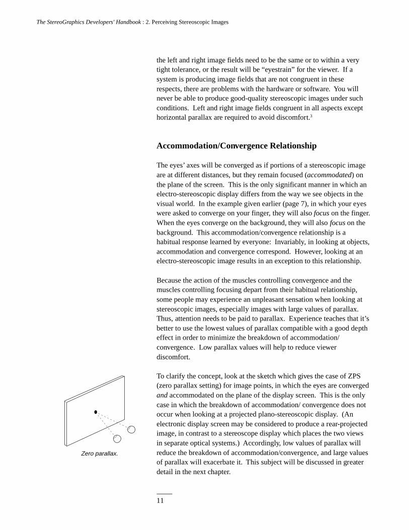
To clarify the concept, look at the sketch which gives the case of ZPS(zero parallax setting) for image points, in which the eyes are convergedand accommodated on the plane of the display screen. This is the onlycase in which the breakdown of accommodation/ convergence does notoccur when looking at a projected plano-stereoscopic display. (Anelectronic display screen may be considered to produce a rear-projectedimage, in contrast to a stereoscope display which places the two viewsin separate optical systems.) Accordingly, low values of parallax willreduce the breakdown of accommodation/convergence, and large valuesof parallax will exacerbate it. This subject will be discussed in greaterdetail in the next chapter.
Zero parallax.
12
The StereoGraphics Developers' Handbook : 2. Perceiving Stereoscopic Images
Control of Parallax
The goal when creating stereoscopic images is to provide the deepesteffect with the lowest values of parallax. This is accomplished in partby reducing the interaxial separation. In only one case, the ZPScondition, will there be no breakdown of the accommodation/convergence relationship. If the composition allows, it is best to placethe principal object(s) at or near the plane of the screen, or to split thedifference in parallax by fixing the ZPS on the middle of an object sothat half of the parallax values will be positive and half negative.
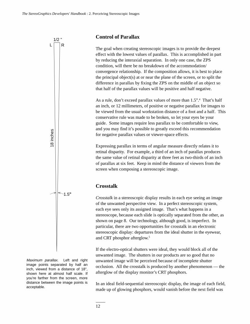
As a rule, don’t exceed parallax values of more than 1.5°.4 That’s halfan inch, or 12 millimeters, of positive or negative parallax for images tobe viewed from the usual workstation distance of a foot and a half. Thisconservative rule was made to be broken, so let your eyes be yourguide. Some images require less parallax to be comfortable to view,and you may find it’s possible to greatly exceed this recommendationfor negative parallax values or viewer-space effects.
Expressing parallax in terms of angular measure directly relates it toretinal disparity. For example, a third of an inch of parallax producesthe same value of retinal disparity at three feet as two-thirds of an inchof parallax at six feet. Keep in mind the distance of viewers from thescreen when composing a stereoscopic image.
Crosstalk
Crosstalk in a stereoscopic display results in each eye seeing an imageof the unwanted perspective view. In a perfect stereoscopic system,each eye sees only its assigned image. That’s what happens in astereoscope, because each slide is optically separated from the other, asshown on page 8. Our technology, although good, is imperfect. Inparticular, there are two opportunities for crosstalk in an electronicstereoscopic display: departures from the ideal shutter in the eyewear,and CRT phosphor afterglow.5
If the electro-optical shutters were ideal, they would block all of theunwanted image. The shutters in our products are so good that nounwanted image will be perceived because of incomplete shutterocclusion. All the crosstalk is produced by another phenomenon — theafterglow of the display monitor’s CRT phosphors.
In an ideal field-sequential stereoscopic display, the image of each field,made up of glowing phosphors, would vanish before the next field was
18 in
ches
1/2 "
1.5
L R
Maximum parallax. Left and right image points separated by half an inch, viewed from a distance of 18", shown here at almost half scale. If you're farther from the screen, more distance between the image points is acceptable.
o
13
The StereoGraphics Developers' Handbook : 2. Perceiving Stereoscopic Images
written, but that’s not what happens. After the right image is written, itwill persist while the left image is being written. Thus, an unwantedfading right image will persist into the left image (and vice versa).
The term ghosting is used to describe perceived crosstalk. Stereoscopistshave also used the term “leakage” to describe this phenomenon. Theperception of ghosting varies with the brightness of the image, color, and— most importantly — parallax and image contrast. Images with largevalues of parallax will have more ghosting than images with lowparallax. High-contrast images, like black lines on a white background,will show the most ghosting. Given the present state of the art ofmonitors and their display tubes, the green phosphor has the longestafterglow and produces the most ghosting. If an image is creatingghosting problems, try reducing the green in the image.
Curing the Problems
The breakdown of the accommodation/convergence relationship andghost images produced by crosstalk can detract from the enjoyment of astereoscopic image. Fortunately, the cure for both problems is the same:Use the lowest values of parallax to produce a good stereoscopic effect.
As corresponding points approach the ZPS, both problems go away! Ascorresponding points move closer together, accommodation andconvergence approach their usual relationship and the ghost image alsodiminishes, since it will increasingly correspond with the wanted image.
Summary
We have seen that a stereoscopic display differs from a planar display byincorporating parallax. Parallax is classified into positive parallax,which produces an image distant from the viewer (in CRT space), andnegative parallax, which produces off-screen effects or images in viewerspace. The perceptual artifacts introduced by the limitations of displaytubes and the human visual system may be held to tolerable limits byproperly adjusting the parallax, a subject which will be addressed furtherin the next chapter.
References
1. Wheatstone, Charles. On some remarkable, and hitherto unobserved,phenomena of binocular vision (Part the first). PhilosophicalTransactions of the Royal Society of London, 1838, 371-94.
14
The StereoGraphics Developers' Handbook : 2. Perceiving Stereoscopic Images
2. Lipton, Lenny, et al. Stereoscopic Television System. U.S. Patent No.4,523,226, June 11, 1985.
3. Lipton, Lenny. Binocular symmetries as criteria for the successfultransmission of images. Processing and Display of Three-DimensionalData II, SPIE Vol.507, 1984.
4. Valyus, N.A. Stereoscopy. London, New York: Focal Press, 1962.
5. Lipton, Lenny. Factors affecting ghosting in a time-multiplexedplano-stereoscopic CRT display system. SPIE Proceedings, Vol.761,1987.
15
The StereoGraphics Developers' Handbook : 3. Composition
C H A P T E R 3
Composition
Electro-stereoscopic images have an enhanced quality, but does theaddition of stereopsis signify that such an image is more “realistic” thanthe planar version of that image? The idea that stereoscopic images aremore realistic than their planar counterparts is accepted by many people.One might say that this has become the commonsense point of view.Although the addition of stereopsis to a display adds another depth sense,it is arguable whether this addition makes the display more realistic.
I’m content with the idea that there is an enhancement, but that this ismerely an addition of another depth cue to the display. Stereopsis addsinformation in a form that is both sensually pleasing and useful. If youwant to say it’s more realistic that’s your choice, but technology hasn’treached the point where anybody is fooled into mistaking the display forthe world itself.
As we shall see, a stereoscopic image which has a one-to-onecorrespondence or is isomorphic with the visual world may beuncomfortable to look at, and of questionable value for scientist, engineer,technician, and artist. To understand why, and how to control the uniquevariables of stereoscopic composition, we must first understand them.
There are several ways in which a stereoscopic image may depart frombeing isomorphic with the visual world. We’ll discuss three of theseconditions which involve, in this order, psycho-physics, the psychology of
16
The StereoGraphics Developers' Handbook : 3. Composition
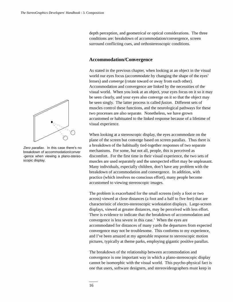
Zero parallax. In this case there's no breakdown of accommodation/conver-gence when viewing a plano-stereo-scopic display.
depth perception, and geometrical or optical considerations. The threeconditions are: breakdown of accommodation/convergence, screensurround conflicting cues, and orthostereoscopic conditions.
Accommodation/Convergence
As stated in the previous chapter, when looking at an object in the visualworld our eyes focus (accommodate by changing the shape of the eyes’lenses) and converge (rotate toward or away from each other).Accommodation and convergence are linked by the necessities of thevisual world. When you look at an object, your eyes focus on it so it maybe seen clearly, and your eyes also converge on it so that the object maybe seen singly. The latter process is called fusion. Different sets ofmuscles control these functions, and the neurological pathways for thesetwo processes are also separate. Nonetheless, we have grownaccustomed or habituated to the linked response because of a lifetime ofvisual experience.
When looking at a stereoscopic display, the eyes accommodate on theplane of the screen but converge based on screen parallax. Thus there isa breakdown of the habitually tied-together responses of two separatemechanisms. For some, but not all, people, this is perceived asdiscomfort. For the first time in their visual experience, the two sets ofmuscles are used separately and the unexpected effort may be unpleasant.Many individuals, especially children, don’t have any problem with thebreakdown of accommodation and convergence. In addition, withpractice (which involves no conscious effort), many people becomeaccustomed to viewing stereoscopic images.
The problem is exacerbated for the small screens (only a foot or twoacross) viewed at close distances (a foot and a half to five feet) that arecharacteristic of electro-stereoscopic workstation displays. Large-screendisplays, viewed at greater distances, may be perceived with less effort.There is evidence to indicate that the breakdown of accommodation andconvergence is less severe in this case.1 When the eyes areaccommodated for distances of many yards the departures from expectedconvergence may not be troublesome. This conforms to my experience,and I’ve been amazed at my agreeable response to stereoscopic motionpictures, typically at theme parks, employing gigantic positive parallax.
The breakdown of the relationship between accommodation andconvergence is one important way in which a plano-stereoscopic displaycannot be isomorphic with the visual world. This psycho-physical fact isone that users, software designers, and stereovideographers must keep in
17
The StereoGraphics Developers' Handbook : 3. Composition
mind, because a plano-stereoscopic display can never overcome thisartifact. A direct consequence of this is that, as a rule of thumb, oneshould keep parallax to the minimum required for a satisfactory deptheffect.
Accommodation and convergence don’t provide the mind with depthinformation.2 This statement is at odds with the belief of manystereoscopists. In the case of convergence, the evidence that it providesany depth information has not been clearly demonstrated. Foraccommodation, it may be the perception of blur (rather than muscleschanging the shape of the eyes’ lenses) that provides depth information.Therefore, the breakdown of accommodation/convergence probablydoesn’t result in a conflict of depth cues. While it may seem like a finedistinction, the conflict is actually based on a departure from thehabituated relationship of two sets of neural pathways and the musclesthey control.
The accommodation/convergence relationship is habitual and learned; itis not a physiological given. People who are experienced in looking atstereoscopic images may no longer have the usual accommodation/convergence response. This can be a disadvantage, because stereoscopicimages so composed may exceed the limits of what is comfortable foruntrained people. Bear this in mind and avoid composing images whichtax other people’s visual systems. It’s a good idea to try your images outon people who are not adept.
Screen Surround
Looking at a television or monitor screen is like looking through awindow, and the plane of the display screen is called the stereo window.The vertical and horizontal edges of the screen are called the surround.As discussed earlier, a stereo image can be thought of as existing in tworegions: one within the cathode ray tube (CRT space) and one between itand the viewer (viewer space). When composing a stereoscopic image,there’s a basic decision to be made: where to position the scene or theobject with respect to the screen surface or stereo window (the boundarylayer separating CRT space from viewer space).
It’s best if the surround doesn’t cut off a portion of an object withnegative parallax. (By convention, as explained, an object with negativeparallax exists in viewer space.) If the surround cuts off or touches anobject in viewer space, there will be a conflict of depth cues which manypeople find objectionable. Because this anomaly never occurs in thevisual world, we lack the vocabulary to describe it, so people typically
18
The StereoGraphics Developers' Handbook : 3. Composition
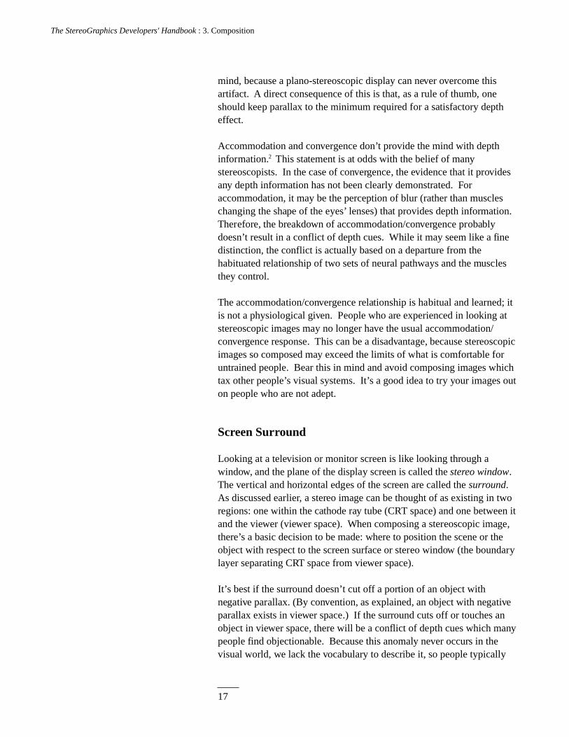
Interposition and parallax cues. No conflict of cues: the top drawing shows the globe, in viewer space with negative parallax, centered within the screen surround. Conflict of cues: the lower drawing shows the globe cut off by the surround. In this case the interposition cue tells the eye-brain the globe is behind the surround, but the stereopsis cue tells the eye-brain the globe is in front of the surround.
call the effect “blurry,” or “out of focus.” For many people, this conflictof cues will result in the image being pulled back into CRT space, despitethe fact that it has negative parallax.3
Here’s what’s happening: One cue, the cue of interposition, tells you theobject must be behind the window since it’s cut off by the surround. Theother cue, the stereoscopic cue provided by parallax, tells you that theobject is in front of the window. Our experience tells us that when weare looking through a window, objects cannot be between the windowand us. You can accept the stereo illusion only if the object is notoccluded by a portion of the window.
Objects touching the horizontal portions of the surround, top and bottom,are less troublesome than objects touching the vertical portions of thesurround. Objects can be hung from or cut off by the horizontal portionsof the surround and still look all right.
In this regard, the vertical portion of the surround leads to problems.That’s because of the paradoxical stereoscopic window effect. Whenlooking outdoors through a real window — for example, out the left edgeof the window — the right eye sees more of the outdoor image at theedge than the left eye sees. The same kind of experience occurs for theright edge of the window. The difficulty arises in stereoscopic imagingfrom the following fact: The right eye, when looking at the left edge ofthe screen for objects with negative parallax, will see less image, and theleft eye will see more. This is at odds with what we see when we lookthrough a real window. This departure from our usual experience may bethe cause of the exacerbated difficulty associated with the perception ofimages at the vertical surrounds.
There's an exception to this which is especially important for gamesdevelopers. Objects which are rapidly racing off the screen may havevery large negative parallax values. They tend to look just fine. It's whensuch objects linger at the screen surround that many people haveperceptual problems.
Orthostereoscopy
There are three conditions to be fulfilled for a stereoscopic image to beorthostereoscopic.4 Such an image would be isomorphic — in terms ofthe stereoscopic depth cue and perspective considerations — with thevisual world. First, images of very distant objects must cause theviewer’s eyes to have parallel lens axes. Second, the distance between
19
The StereoGraphics Developers' Handbook : 3. Composition
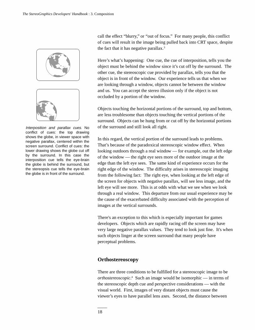
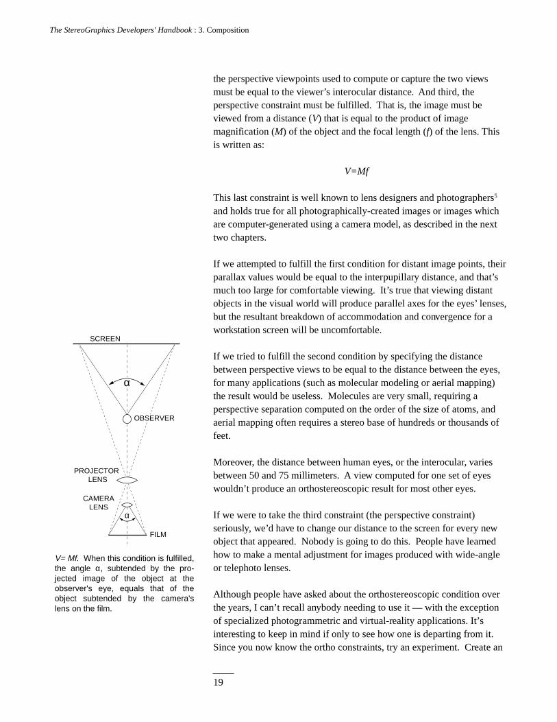
the perspective viewpoints used to compute or capture the two viewsmust be equal to the viewer’s interocular distance. And third, theperspective constraint must be fulfilled. That is, the image must beviewed from a distance (V) that is equal to the product of imagemagnification (M) of the object and the focal length (f) of the lens. Thisis written as:
V=Mf
This last constraint is well known to lens designers and photographers5
and holds true for all photographically-created images or images whichare computer-generated using a camera model, as described in the nexttwo chapters.
If we attempted to fulfill the first condition for distant image points, theirparallax values would be equal to the interpupillary distance, and that’smuch too large for comfortable viewing. It’s true that viewing distantobjects in the visual world will produce parallel axes for the eyes’ lenses,but the resultant breakdown of accommodation and convergence for aworkstation screen will be uncomfortable.
If we tried to fulfill the second condition by specifying the distancebetween perspective views to be equal to the distance between the eyes,for many applications (such as molecular modeling or aerial mapping)the result would be useless. Molecules are very small, requiring aperspective separation computed on the order of the size of atoms, andaerial mapping often requires a stereo base of hundreds or thousands offeet.
Moreover, the distance between human eyes, or the interocular, variesbetween 50 and 75 millimeters. A view computed for one set of eyeswouldn’t produce an orthostereoscopic result for most other eyes.
If we were to take the third constraint (the perspective constraint)seriously, we’d have to change our distance to the screen for every newobject that appeared. Nobody is going to do this. People have learnedhow to make a mental adjustment for images produced with wide-angleor telephoto lenses.
Although people have asked about the orthostereoscopic condition overthe years, I can’t recall anybody needing to use it — with the exceptionof specialized photogrammetric and virtual-reality applications. It’sinteresting to keep in mind if only to see how one is departing from it.Since you now know the ortho constraints, try an experiment. Create an
SCREEN
OBSERVER
CAMERA LENS
FILM
V= Mf. When this condition is fulfilled, the angle α, subtended by the pro-jected image of the object at the observer's eye, equals that of the object subtended by the camera's lens on the film.
PROJECTOR LENS
α
α
20
The StereoGraphics Developers' Handbook : 3. Composition
image conforming to these constraints. How does it look? Now changethe compositional parameters in accordance with the advice given here.
If the image looks good, that’s good enough.
ZPS and HIT
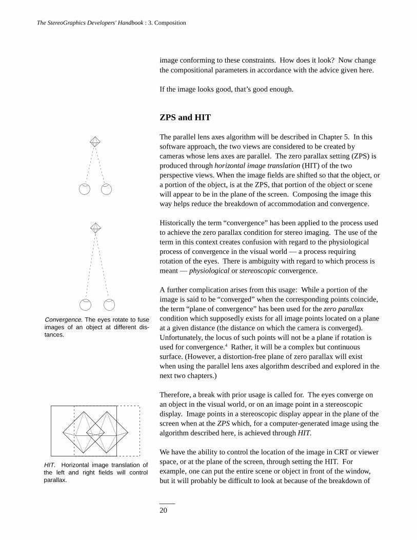
The parallel lens axes algorithm will be described in Chapter 5. In thissoftware approach, the two views are considered to be created bycameras whose lens axes are parallel. The zero parallax setting (ZPS) isproduced through horizontal image translation (HIT) of the twoperspective views. When the image fields are shifted so that the object, ora portion of the object, is at the ZPS, that portion of the object or scenewill appear to be in the plane of the screen. Composing the image thisway helps reduce the breakdown of accommodation and convergence.
Historically the term “convergence” has been applied to the process usedto achieve the zero parallax condition for stereo imaging. The use of theterm in this context creates confusion with regard to the physiologicalprocess of convergence in the visual world — a process requiringrotation of the eyes. There is ambiguity with regard to which process ismeant — physiological or stereoscopic convergence.
A further complication arises from this usage: While a portion of theimage is said to be “converged” when the corresponding points coincide,the term “plane of convergence” has been used for the zero parallaxcondition which supposedly exists for all image points located on a planeat a given distance (the distance on which the camera is converged).Unfortunately, the locus of such points will not be a plane if rotation isused for convergence.4 Rather, it will be a complex but continuoussurface. (However, a distortion-free plane of zero parallax will existwhen using the parallel lens axes algorithm described and explored in thenext two chapters.)
Therefore, a break with prior usage is called for. The eyes converge onan object in the visual world, or on an image point in a stereoscopicdisplay. Image points in a stereoscopic display appear in the plane of thescreen when at the ZPS which, for a computer-generated image using thealgorithm described here, is achieved through HIT.
We have the ability to control the location of the image in CRT or viewerspace, or at the plane of the screen, through setting the HIT. Forexample, one can put the entire scene or object in front of the window,but it will probably be difficult to look at because of the breakdown of
HIT. Horizontal image translation of the left and right fields will control parallax.
Convergence. The eyes rotate to fuse images of an object at different dis-tances.
21
The StereoGraphics Developers' Handbook : 3. Composition
accommodation and convergence, or because of the conflict of cues atthe screen surround. Much of the time you’re better off making theimage appear to be seen through a window. This is especially true ifyou’re creating a scenic view or an interior, as we will discuss in amoment.
On the other hand, many computer-generated images involve a singleobject — for example a molecule or a machine part. For this class ofcompositions try placing the center of the object in the plane of thescreen with some of it in viewer space and some of it in CRT space. Thistends to reduce the breakdown of accommodation and convergence.Where you place the object is also an aesthetic decision.
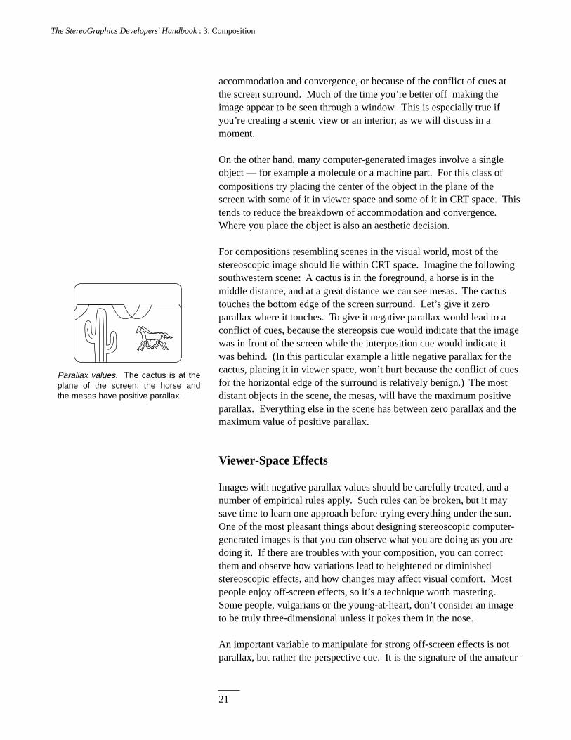
For compositions resembling scenes in the visual world, most of thestereoscopic image should lie within CRT space. Imagine the followingsouthwestern scene: A cactus is in the foreground, a horse is in themiddle distance, and at a great distance we can see mesas. The cactustouches the bottom edge of the screen surround. Let’s give it zeroparallax where it touches. To give it negative parallax would lead to aconflict of cues, because the stereopsis cue would indicate that the imagewas in front of the screen while the interposition cue would indicate itwas behind. (In this particular example a little negative parallax for thecactus, placing it in viewer space, won’t hurt because the conflict of cuesfor the horizontal edge of the surround is relatively benign.) The mostdistant objects in the scene, the mesas, will have the maximum positiveparallax. Everything else in the scene has between zero parallax and themaximum value of positive parallax.
Viewer-Space Effects
Images with negative parallax values should be carefully treated, and anumber of empirical rules apply. Such rules can be broken, but it maysave time to learn one approach before trying everything under the sun.One of the most pleasant things about designing stereoscopic computer-generated images is that you can observe what you are doing as you aredoing it. If there are troubles with your composition, you can correctthem and observe how variations lead to heightened or diminishedstereoscopic effects, and how changes may affect visual comfort. Mostpeople enjoy off-screen effects, so it’s a technique worth mastering.Some people, vulgarians or the young-at-heart, don’t consider an imageto be truly three-dimensional unless it pokes them in the nose.
An important variable to manipulate for strong off-screen effects is notparallax, but rather the perspective cue. It is the signature of the amateur
Parallax values. The cactus is at the plane of the screen; the horse and the mesas have positive parallax.
22
The StereoGraphics Developers' Handbook : 3. Composition
2'
4'
2'
1'
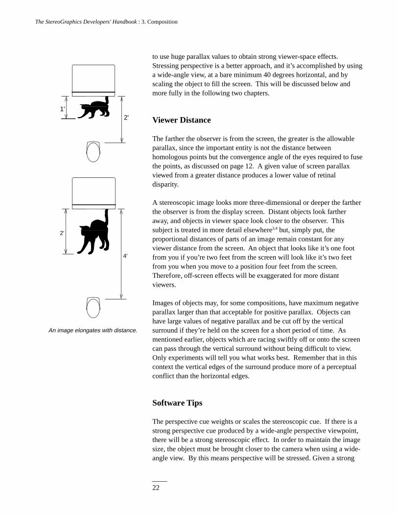
An image elongates with distance.
to use huge parallax values to obtain strong viewer-space effects.Stressing perspective is a better approach, and it’s accomplished by usinga wide-angle view, at a bare minimum 40 degrees horizontal, and byscaling the object to fill the screen. This will be discussed below andmore fully in the following two chapters.
Viewer Distance
The farther the observer is from the screen, the greater is the allowableparallax, since the important entity is not the distance betweenhomologous points but the convergence angle of the eyes required to fusethe points, as discussed on page 12. A given value of screen parallaxviewed from a greater distance produces a lower value of retinaldisparity.
A stereoscopic image looks more three-dimensional or deeper the fartherthe observer is from the display screen. Distant objects look fartheraway, and objects in viewer space look closer to the observer. Thissubject is treated in more detail elsewhere3,4 but, simply put, theproportional distances of parts of an image remain constant for anyviewer distance from the screen. An object that looks like it’s one footfrom you if you’re two feet from the screen will look like it’s two feetfrom you when you move to a position four feet from the screen.Therefore, off-screen effects will be exaggerated for more distantviewers.
Images of objects may, for some compositions, have maximum negativeparallax larger than that acceptable for positive parallax. Objects canhave large values of negative parallax and be cut off by the verticalsurround if they’re held on the screen for a short period of time. Asmentioned earlier, objects which are racing swiftly off or onto the screencan pass through the vertical surround without being difficult to view.Only experiments will tell you what works best. Remember that in thiscontext the vertical edges of the surround produce more of a perceptualconflict than the horizontal edges.
Software Tips
The perspective cue weights or scales the stereoscopic cue. If there is astrong perspective cue produced by a wide-angle perspective viewpoint,there will be a strong stereoscopic effect. In order to maintain the imagesize, the object must be brought closer to the camera when using a wide-angle view. By this means perspective will be stressed. Given a strong
23
The StereoGraphics Developers' Handbook : 3. Composition
stereoscopic effect, the values of parallax may be lowered by reducingthe interaxial distance. The stereopsis depth cue may be reduced in thiscase because the extrastereoscopic depth cue of perspective has beenstrengthened. The reduction in parallax will diminish the breakdown ofconvergence and accommodation and ghosting, thereby producing animage more pleasing to view.
Here’s more advice for software developers who are dealing with imagesof single objects centered in the middle of the screen: When an imageinitially appears on the screen, let’s allow image points at the center ofthe object to default to the ZPS condition. Moreover, let’s maintain theZPS within the object even during zooming or changing object size.Some people don’t like this notion. They think that the ZPS ought to bein front of the object when it is far away (small) and behind the objectwhen it is close (big), to simulate what they suppose happens in thevisual world. But in the visual world the eyes remain converged on theobject as it changes distance; hence, retinal disparity, the counterpart ofscreen parallax, remains constant.
The depth cue of relative size is sufficient to make the object appear to benear or far, or changing distance, and often we’re only trying to scale theimage to make it a convenient size. Its center ought to remain at theplane of the screen for easiest viewing.
One thing that's fun about stereoscopic displays has nothing to do withthe depth effect. Rather it has to do with glitter, sparkle, and luster.These effects are related to the fact that certain objects refract or reflectlight differently to each eye. For example, looking at a diamond, youmay see highlight with one eye but not the other. Such is the nature ofglitter. This is a fun effect that can be added to a stereoscopic image. Italso is an effect that can be used for fire to make it look alive. Forexample, if you use bright orange for one view and red for the other, youwill create the effect of scintillation.
Proposed Standard
Here is a proposed standard for stereoscopic software to help userscontrol the two basic variables of stereoscopic composition: interaxialdistance (tc) and HIT. The arrow keys N, S, E, and W should be used tocontrol these functions. N and S are devoted to the interaxial setting —N for increasing the distance between camera axes, and S for decreasingthe distance.
24
The StereoGraphics Developers' Handbook : 3. Composition
7 8 9
456
1 2 3
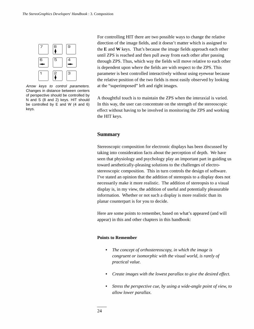
Arrow keys to control parameters. Changes in distance between centers of perspective should be controlled by N and S (8 and 2) keys. HIT should be controlled by E and W (4 and 6) keys.
For controlling HIT there are two possible ways to change the relativedirection of the image fields, and it doesn’t matter which is assigned tothe E and W keys. That’s because the image fields approach each otheruntil ZPS is reached and then pull away from each other after passingthrough ZPS. Thus, which way the fields will move relative to each otheris dependent upon where the fields are with respect to the ZPS. Thisparameter is best controlled interactively without using eyewear becausethe relative position of the two fields is most easily observed by lookingat the “superimposed” left and right images.
A thoughtful touch is to maintain the ZPS when the interaxial is varied.In this way, the user can concentrate on the strength of the stereoscopiceffect without having to be involved in monitoring the ZPS and workingthe HIT keys.
Summary
Stereoscopic composition for electronic displays has been discussed bytaking into consideration facts about the perception of depth. We haveseen that physiology and psychology play an important part in guiding ustoward aesthetically-pleasing solutions to the challenges of electro-stereoscopic composition. This in turn controls the design of software.I’ve stated an opinion that the addition of stereopsis to a display does notnecessarily make it more realistic. The addition of stereopsis to a visualdisplay is, in my view, the addition of useful and potentially pleasurableinformation. Whether or not such a display is more realistic than itsplanar counterpart is for you to decide.
Here are some points to remember, based on what’s appeared (and willappear) in this and other chapters in this handbook:
Points to Remember
• The concept of orthostereoscopy, in which the image iscongruent or isomorphic with the visual world, is rarely ofpractical value.
• Create images with the lowest parallax to give the desired effect.
• Stress the perspective cue, by using a wide-angle point of view, toallow lower parallax.
25
The StereoGraphics Developers' Handbook : 3. Composition
• Use ZPS for the center of an image of a single object to reducethe breakdown of accommodation/convergence.
• Avoid touching the surround with images having negativeparallax.
• When changing the scale of an image of a single object, it maybe best to allow the ZPS to remain at the object’s center.
• Remember that the image should be easy to look at initially.Build in default conditions so that the image boots up with aproperly placed ZPS, and maintains the constancy of ZPS withchanges of scale, angle of view, and changes of the interaxialdistance.
• Use the parallel axes camera model (to be discussed in the nexttwo chapters). Do not use rotation for the creation ofstereopairs.
• Don’t exceed 20 millimeters for positive parallax on a displayscreen. This is a rough rule of thumb. Judge for yourself.
• Observe the image without glasses to see where you haveconverged and to see the maximum values of parallax.
• For scenic views, try putting the ZPS on the closest foregroundobject, and be careful to control the maximum positive values ofparallax produced by distant image points. You can achieve thelatter by reducing the interaxial separation and/or increasing theangle of view.
• If you see annoying crosstalk, and you have adjusted the parallaxto low values, try changing the color of the image. Because oflong phosphor persistence, green tends to ghost the most.
• Once you know the basics, composing stereoscopic images is anart, not a science.
There are tens of thousands of people in the world who are usingelectronic stereoscopic displays. A few years ago there weren’t even ahundred. In the next years a great deal will be learned about thecomposition and aesthetics of such images. It may well be that some ofthe solutions suggested here will be improved or even overthrown.That’s fine, because we’re at the beginning of the exploration of themedium — an exploration that is likely to continue for decades.
26
The StereoGraphics Developers' Handbook : 3. Composition
References
1. Inoue, T., and Ohzu, H. Measurement of the human factors of3-D images on a large screen. Large-Screen Projection Displays II, SPIEVol.1255, 1990.
2. Kaufman, Lloyd. Sight and mind: An introduction to visualperception. New York: Oxford University Press, 1974.
3. Lipton, Lenny. Foundations of the stereoscopic cinema. New York:Van Nostrand Reinhold, 1982.
4. Spottiswoode, Raymond, and Spottiswoode, Nigel. The theory ofstereoscopic transmission and its application to the motion picture.Berkeley: University of California Press, 1953.
5. Lipton, Lenny. Independent filmmaking. New York: Simon &Schuster, 1983.
27
The StereoGraphics Developers' Handbook: 4. Stereo-Vision Formats
C H A P T E R 4
Stereo-Vision Formats
What's a Format?
There are several distinct means for preparing time-shared multiplexedimages for stereo-vision electronic displays. Furthermore, the conceptof format is distinct from the selection technique, or the means forproviding each eye with its needed image (and rejecting theunnecessary image). Format and image selection must work together,and in designing such a system the selection technique may determinethe format. For example, if the image is to be viewed in a stereoscopesimilar to the popular View-Master viewer (as mentioned in Chapter 1),the left and right images may be formatted so that they are side-by-sideon the display screen.
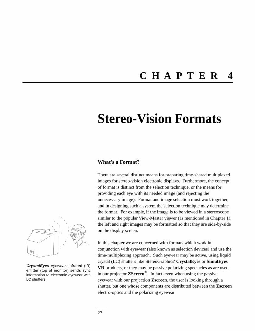
In this chapter we are concerned with formats which work inconjunction with eyewear (also known as selection devices) and use thetime-multiplexing approach. Such eyewear may be active, using liquidcrystal (LC) shutters like StereoGraphics' CrystalEyes or SimulEyesVR products, or they may be passive polarizing spectacles as are usedin our projector ZScreen®. In fact, even when using the passiveeyewear with our projection Zscreen, the user is looking through ashutter, but one whose components are distributed between the Zscreenelectro-optics and the polarizing eyewear.
CrystalEyes eyewear. Infrared (IR)emitter (top of monitor) sends syncinformation to electronic eyewear withLC shutters.
28
The StereoGraphics Developers' Handbook: 4. Stereo-Vision Formats
The most widespread method for viewing electronic stereo-vision imagesuses CrystalEyes on workstations for scientific visualization applicationssuch as molecular modeling. In the most general terms, the format usedby CrystalEyes is called the alternate field, field-sequential, or time-multiplexed technique.
Interlace Stereo
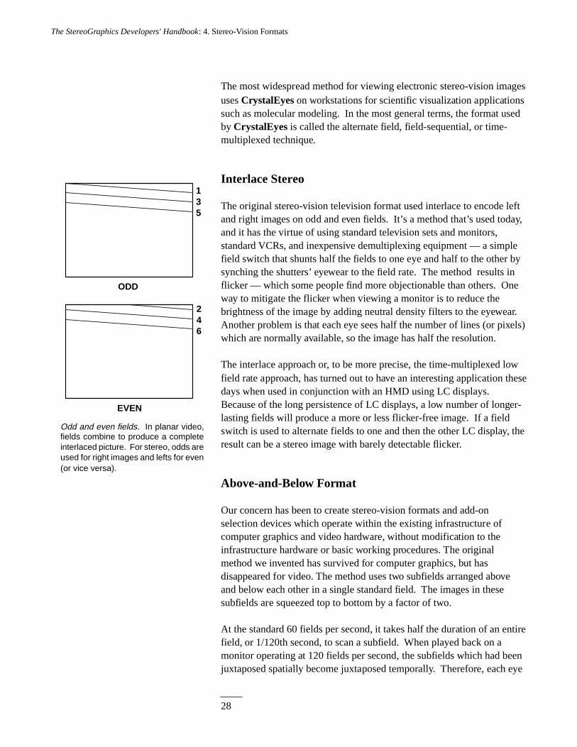
The original stereo-vision television format used interlace to encode leftand right images on odd and even fields. It’s a method that’s used today,and it has the virtue of using standard television sets and monitors,standard VCRs, and inexpensive demultiplexing equipment — a simplefield switch that shunts half the fields to one eye and half to the other bysynching the shutters’ eyewear to the field rate. The method results inflicker — which some people find more objectionable than others. Oneway to mitigate the flicker when viewing a monitor is to reduce thebrightness of the image by adding neutral density filters to the eyewear.Another problem is that each eye sees half the number of lines (or pixels)which are normally available, so the image has half the resolution.
The interlace approach or, to be more precise, the time-multiplexed lowfield rate approach, has turned out to have an interesting application thesedays when used in conjunction with an HMD using LC displays.Because of the long persistence of LC displays, a low number of longer-lasting fields will produce a more or less flicker-free image. If a fieldswitch is used to alternate fields to one and then the other LC display, theresult can be a stereo image with barely detectable flicker.
Above-and-Below Format
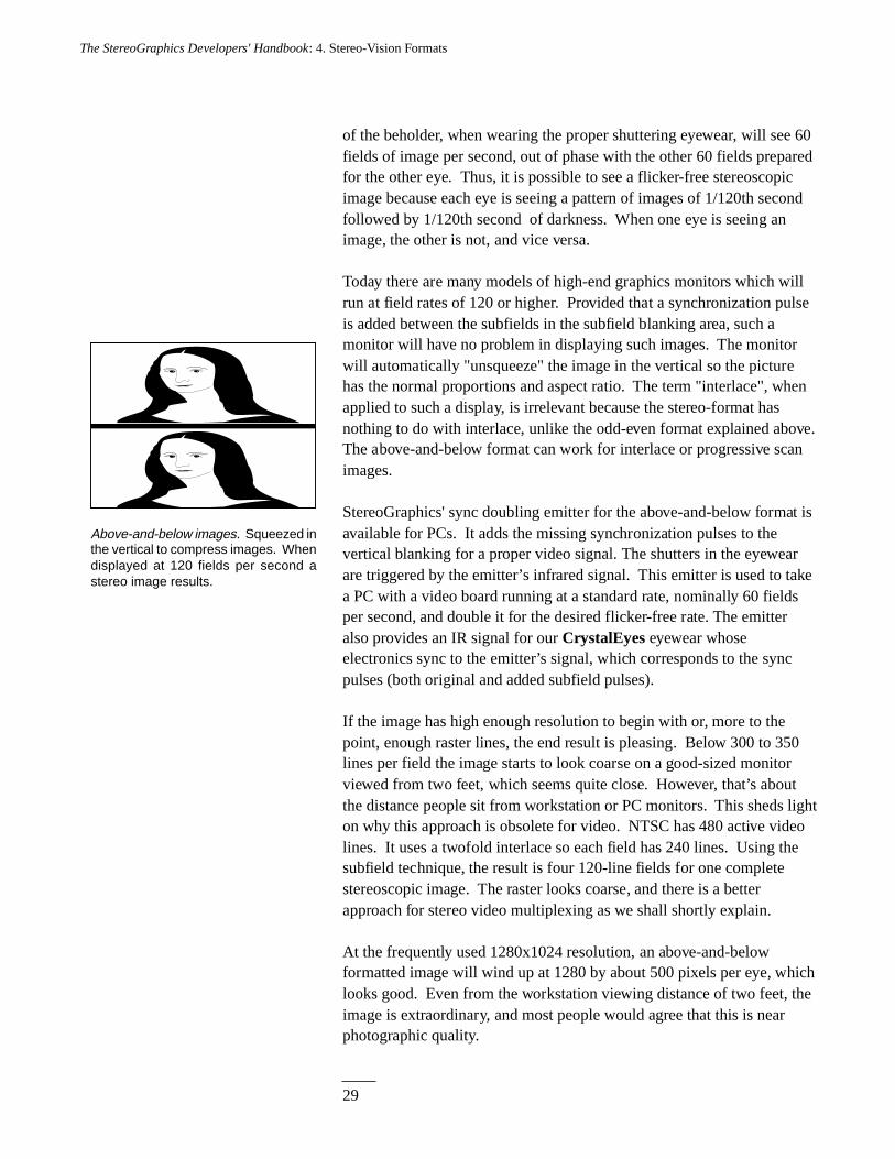
Our concern has been to create stereo-vision formats and add-onselection devices which operate within the existing infrastructure ofcomputer graphics and video hardware, without modification to theinfrastructure hardware or basic working procedures. The originalmethod we invented has survived for computer graphics, but hasdisappeared for video. The method uses two subfields arranged aboveand below each other in a single standard field. The images in thesesubfields are squeezed top to bottom by a factor of two.
At the standard 60 fields per second, it takes half the duration of an entirefield, or 1/120th second, to scan a subfield. When played back on amonitor operating at 120 fields per second, the subfields which had beenjuxtaposed spatially become juxtaposed temporally. Therefore, each eye
Odd and even fields. In planar video,fields combine to produce a completeinterlaced picture. For stereo, odds areused for right images and lefts for even(or vice versa).
ODD
EVEN
1 3 5
2 4 6
29
The StereoGraphics Developers' Handbook: 4. Stereo-Vision Formats
of the beholder, when wearing the proper shuttering eyewear, will see 60fields of image per second, out of phase with the other 60 fields preparedfor the other eye. Thus, it is possible to see a flicker-free stereoscopicimage because each eye is seeing a pattern of images of 1/120th secondfollowed by 1/120th second of darkness. When one eye is seeing animage, the other is not, and vice versa.
Today there are many models of high-end graphics monitors which willrun at field rates of 120 or higher. Provided that a synchronization pulseis added between the subfields in the subfield blanking area, such amonitor will have no problem in displaying such images. The monitorwill automatically "unsqueeze" the image in the vertical so the picturehas the normal proportions and aspect ratio. The term "interlace", whenapplied to such a display, is irrelevant because the stereo-format hasnothing to do with interlace, unlike the odd-even format explained above.The above-and-below format can work for interlace or progressive scanimages.
StereoGraphics' sync doubling emitter for the above-and-below format isavailable for PCs. It adds the missing synchronization pulses to thevertical blanking for a proper video signal. The shutters in the eyewearare triggered by the emitter’s infrared signal. This emitter is used to takea PC with a video board running at a standard rate, nominally 60 fieldsper second, and double it for the desired flicker-free rate. The emitteralso provides an IR signal for our CrystalEyes eyewear whoseelectronics sync to the emitter’s signal, which corresponds to the syncpulses (both original and added subfield pulses).
If the image has high enough resolution to begin with or, more to thepoint, enough raster lines, the end result is pleasing. Below 300 to 350lines per field the image starts to look coarse on a good-sized monitorviewed from two feet, which seems quite close. However, that’s aboutthe distance people sit from workstation or PC monitors. This sheds lighton why this approach is obsolete for video. NTSC has 480 active videolines. It uses a twofold interlace so each field has 240 lines. Using thesubfield technique, the result is four 120-line fields for one completestereoscopic image. The raster looks coarse, and there is a betterapproach for stereo video multiplexing as we shall shortly explain.
At the frequently used 1280x1024 resolution, an above-and-belowformatted image will wind up at 1280 by about 500 pixels per eye, whichlooks good. Even from the workstation viewing distance of two feet, theimage is extraordinary, and most people would agree that this is nearphotographic quality.
Above-and-below images. Squeezed inthe vertical to compress images. Whendisplayed at 120 fields per second astereo image results.
30
The StereoGraphics Developers' Handbook: 4. Stereo-Vision Formats
Stereo-Ready Computers
These days most graphics computers, like those from Silicon Graphics(SGI), Sun, DEC, IBM, and HP, use a double buffering technique to runtheir machines at a true 120 fields per second rate. Each field has avertical blanking area associated with it which has a synchronizationpulse. These computers are intrinsically outputting a high field rate andthey don’t need the above-and-below solution to make flicker-free stereoimages, so they don’t need a sync-doubling emitter to add the missingsync pulse. These computers are all outfitted with a jack that accepts theStereoGraphics standard emitter, which watches for sync pulses andbroadcasts the IR signal with each pulse. Most of these machines stilloffer a disproportionately higher pixel count in the horizontal comparedwith the vertical.
Some aficionados will insist that square pixels are de rigueur for high-end graphics, but the above-and-below format (or most stereo-readygraphics computers) produces oblong pixels — pixels which are longerin the vertical than they are in the horizontal. The popular 1280x1024display produces a ratio of horizontal to vertical pixels of about 1.3:1,which is the aspect ratio of most display screens, so the result is squarepixels. But in the above-and-below stereo-vision version for thisresolution, the ratio of horizontal to vertical pixels for each eye is morelike 2.6:1, and the result is a pixel longer than it is high by a factor oftwo.
SGI’s high-end machines, the Onyx® and Crimson® lines, may beconfigured to run square-pixel windowed stereo with separateaddressable buffers for left and right eye views, at 960x680 pixels per eye(108 fields per second). This does not require any more pixel memorythan already exists to support the planar 1280x1024. Some SGI high-end computers have additional display RAM available, and they cansupport other square-pixel windowed stereo resolutions, though higherresolutions come at the expense of field rate. For example, such high-endhigh-display-memory SGI systems support 1024x768 pixels per eye butonly at 96 fields per second, which is high enough to have a flicker freeeffect for all but very bright images.
For most applications, having pixels which are not perfectly square canresult in a good-looking picture. The higher the resolution of the image,or the more pixels available for image forming, the less concern theshape of the pixels is.
31
The StereoGraphics Developers' Handbook: 4. Stereo-Vision Formats
Side-by-Side
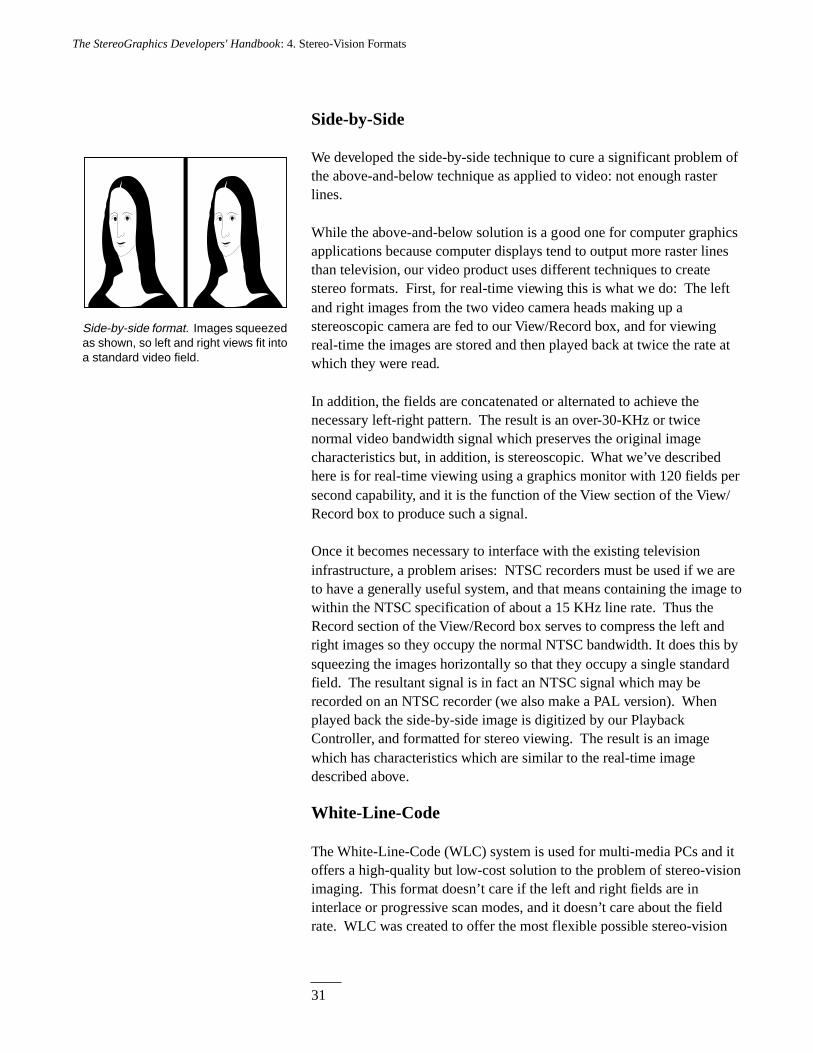
We developed the side-by-side technique to cure a significant problem ofthe above-and-below technique as applied to video: not enough rasterlines.
While the above-and-below solution is a good one for computer graphicsapplications because computer displays tend to output more raster linesthan television, our video product uses different techniques to createstereo formats. First, for real-time viewing this is what we do: The leftand right images from the two video camera heads making up astereoscopic camera are fed to our View/Record box, and for viewingreal-time the images are stored and then played back at twice the rate atwhich they were read.
In addition, the fields are concatenated or alternated to achieve thenecessary left-right pattern. The result is an over-30-KHz or twicenormal video bandwidth signal which preserves the original imagecharacteristics but, in addition, is stereoscopic. What we’ve describedhere is for real-time viewing using a graphics monitor with 120 fields persecond capability, and it is the function of the View section of the View/Record box to produce such a signal.
Once it becomes necessary to interface with the existing televisioninfrastructure, a problem arises: NTSC recorders must be used if we areto have a generally useful system, and that means containing the image towithin the NTSC specification of about a 15 KHz line rate. Thus theRecord section of the View/Record box serves to compress the left andright images so they occupy the normal NTSC bandwidth. It does this bysqueezing the images horizontally so that they occupy a single standardfield. The resultant signal is in fact an NTSC signal which may berecorded on an NTSC recorder (we also make a PAL version). Whenplayed back the side-by-side image is digitized by our PlaybackController, and formatted for stereo viewing. The result is an imagewhich has characteristics which are similar to the real-time imagedescribed above.
White-Line-Code
The White-Line-Code (WLC) system is used for multi-media PCs and itoffers a high-quality but low-cost solution to the problem of stereo-visionimaging. This format doesn’t care if the left and right fields are ininterlace or progressive scan modes, and it doesn’t care about the fieldrate. WLC was created to offer the most flexible possible stereo-vision
Side-by-side format. Images squeezedas shown, so left and right views fit intoa standard video field.
32
The StereoGraphics Developers' Handbook: 4. Stereo-Vision Formats
system for the content providers, developers, and users. The hardwarecomponents of the WLC allow for rapid user installation.
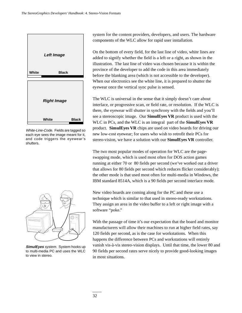
On the bottom of every field, for the last line of video, white lines areadded to signify whether the field is a left or a right, as shown in theillustration. The last line of video was chosen because it is within theprovince of the developer to add the code in this area immediatelybefore the blanking area (which is not accessible to the developer).When our electronics see the white line, it is prepared to shutter theeyewear once the vertical sync pulse is sensed.
The WLC is universal in the sense that it simply doesn’t care aboutinterlace, or progressive scan, or field rate, or resolution. If the WLC isthere, the eyewear will shutter in synchrony with the fields and you’llsee a stereoscopic image. Our SimulEyes VR product is used with theWLC in PCs, and the WLC is an integral part of the SimulEyes VRproduct. SimulEyes VR chips are used on video boards for driving ournew low-cost eyewear; for users who wish to retrofit their PCs forstereo-vision, we have a solution with our SimulEyes VR controller.
The two most popular modes of operation for WLC are the page-swapping mode, which is used most often for DOS action gamesrunning at either 70 or 80 fields per second (we’ve worked out a driverthat allows for 80 fields per second which reduces flicker considerably);the other mode is that used most often for multi-media in Windows, theIBM standard 8514A, which is a 90 fields per second interlace mode.
New video boards are coming along for the PC and these use atechnique which is similar to that used in stereo-ready workstations.They assign an area in the video buffer to a left or right image with asoftware “poke.”
With the passage of time it’s our expectation that the board and monitormanufacturers will allow their machines to run at higher field rates, say120 fields per second, as is the case for workstations. When thishappens the difference between PCs and workstations will entirelyvanish vis-à-vis stereo-vision displays. Until that time, the lower 80 and90 fields per second rates serve nicely to provide good-looking imagesin most situations.
SimulEyes system. System hooks upto multi-media PC and uses the WLCto view in stereo.
Left Image
Right Image
White Black
White Black
White-Line-Code. Fields are tagged soeach eye sees the image meant for it,and code triggers the eyewear ’sshutters.
33
The StereoGraphics Developers' Handbook: 4. Stereo-Vision Formats
Summing Up
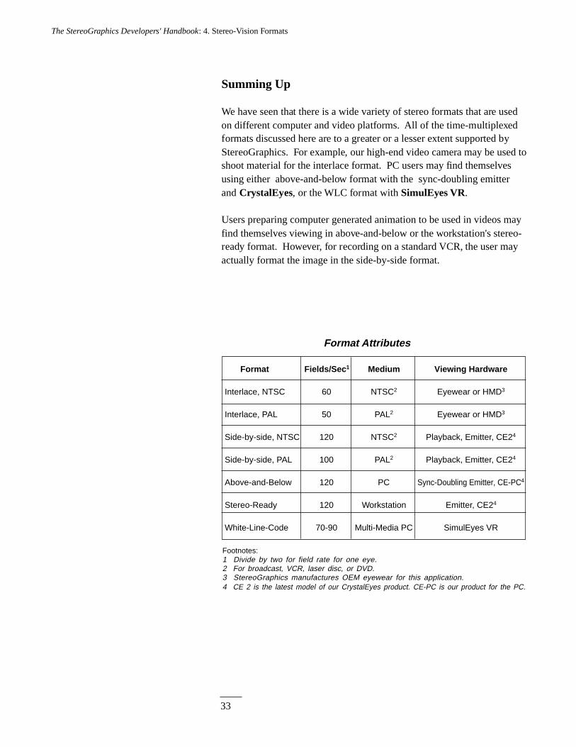
We have seen that there is a wide variety of stereo formats that are usedon different computer and video platforms. All of the time-multiplexedformats discussed here are to a greater or a lesser extent supported byStereoGraphics. For example, our high-end video camera may be used toshoot material for the interlace format. PC users may find themselvesusing either above-and-below format with the sync-doubling emitterand CrystalEyes, or the WLC format with SimulEyes VR.
Users preparing computer generated animation to be used in videos mayfind themselves viewing in above-and-below or the workstation's stereo-ready format. However, for recording on a standard VCR, the user mayactually format the image in the side-by-side format.
Format Fields/Sec 1 Medium Viewing Hardware
Interlace, NTSC 60 NTSC2 Eyewear or HMD3
Interlace, PAL 50 PAL2 Eyewear or HMD3
Side-by-side, NTSC 120 NTSC2 Playback, Emitter, CE24
Side-by-side, PAL 100 PAL2 Playback, Emitter, CE24
Above-and-Below 120 PC Sync-Doubling Emitter, CE-PC4
Stereo-Ready 120 Workstation Emitter, CE24
White-Line-Code 70-90 Multi-Media PC SimulEyes VR
Format Attributes
Footnotes:1 Divide by two for field rate for one eye.2 For broadcast, VCR, laser disc, or DVD.3 StereoGraphics manufactures OEM eyewear for this application.4 CE 2 is the latest model of our CrystalEyes product. CE-PC is our product for the PC.
35
The StereoGraphics Developers' Handbook : 5. Parallel Lens Axes
C H A P T E R 5
A B
C D
A'
B'
D'
C'
AXIS
AXIS
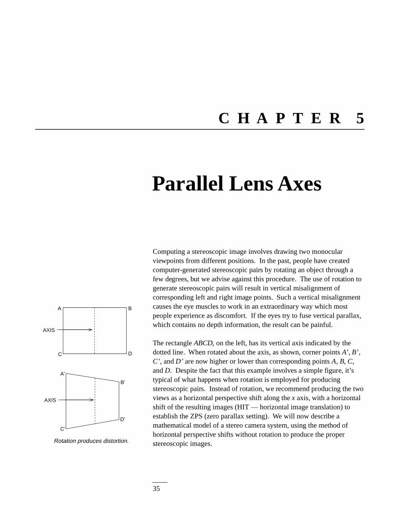
Rotation produces distortion.
Parallel Lens Axes
Computing a stereoscopic image involves drawing two monocularviewpoints from different positions. In the past, people have createdcomputer-generated stereoscopic pairs by rotating an object through afew degrees, but we advise against this procedure. The use of rotation togenerate stereoscopic pairs will result in vertical misalignment ofcorresponding left and right image points. Such a vertical misalignmentcauses the eye muscles to work in an extraordinary way which mostpeople experience as discomfort. If the eyes try to fuse vertical parallax,which contains no depth information, the result can be painful.
The rectangle ABCD, on the left, has its vertical axis indicated by thedotted line. When rotated about the axis, as shown, corner points A’ , B’,C’, and D’ are now higher or lower than corresponding points A, B, C,and D. Despite the fact that this example involves a simple figure, it’stypical of what happens when rotation is employed for producingstereoscopic pairs. Instead of rotation, we recommend producing the twoviews as a horizontal perspective shift along the x axis, with a horizontalshift of the resulting images (HIT — horizontal image translation) toestablish the ZPS (zero parallax setting). We will now describe amathematical model of a stereo camera system, using the method ofhorizontal perspective shifts without rotation to produce the properstereoscopic images.
36
The StereoGraphics Developers' Handbook : 5. Parallel Lens Axes
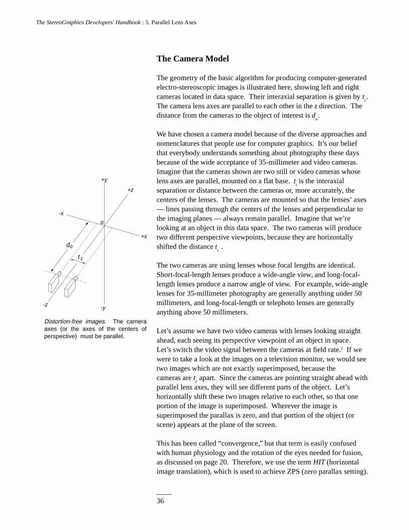
Distortion-free images. The camera axes (or the axes of the centers of perspective) must be parallel.
o
-y
+x
-x
+z
-z
+y
t c
do
The Camera Model
The geometry of the basic algorithm for producing computer-generatedelectro-stereoscopic images is illustrated here, showing left and rightcameras located in data space. Their interaxial separation is given by t
c.
The camera lens axes are parallel to each other in the z direction. Thedistance from the cameras to the object of interest is d
o.
We have chosen a camera model because of the diverse approaches andnomenclatures that people use for computer graphics. It’s our beliefthat everybody understands something about photography these daysbecause of the wide acceptance of 35-millimeter and video cameras.Imagine that the cameras shown are two still or video cameras whoselens axes are parallel, mounted on a flat base. t
c is the interaxial
separation or distance between the cameras or, more accurately, thecenters of the lenses. The cameras are mounted so that the lenses’ axes— lines passing through the centers of the lenses and perpendicular tothe imaging planes — always remain parallel. Imagine that we’relooking at an object in this data space. The two cameras will producetwo different perspective viewpoints, because they are horizontallyshifted the distance t
c .
The two cameras are using lenses whose focal lengths are identical.Short-focal-length lenses produce a wide-angle view, and long-focal-length lenses produce a narrow angle of view. For example, wide-anglelenses for 35-millimeter photography are generally anything under 50millimeters, and long-focal-length or telephoto lenses are generallyanything above 50 millimeters.
Let’s assume we have two video cameras with lenses looking straightahead, each seeing its perspective viewpoint of an object in space.Let’s switch the video signal between the cameras at field rate.1 If wewere to take a look at the images on a television monitor, we would seetwo images which are not exactly superimposed, because thecameras are t
c apart. Since the cameras are pointing straight ahead with
parallel lens axes, they will see different parts of the object. Let’shorizontally shift these two images relative to each other, so that oneportion of the image is superimposed. Wherever the image issuperimposed the parallax is zero, and that portion of the object (orscene) appears at the plane of the screen.
This has been called “convergence,” but that term is easily confusedwith human physiology and the rotation of the eyes needed for fusion,as discussed on page 20. Therefore, we use the term HIT (horizontalimage translation), which is used to achieve ZPS (zero parallax setting).
37
The StereoGraphics Developers' Handbook : 5. Parallel Lens Axes
If the images are horizontally shifted so that some part of the image isperfectly superimposed, that part of the image is at ZPS. Rememberthat our object exists not only in the x and y axes, but also in the z axis.Since it is a three-dimensional object, we can achieve ZPS for only onepoint (or set of points located in a plane) in the object. Let’s supposewe use ZPS on the middle of the object. In this case, those portions ofthe object which are behind the ZPS will have positive parallax, andthose which are in front of the ZPS will have negative parallax.
This parallel lens axes algorithm for stereoscopic computer-generatedimages uses two camera viewpoints, with parallel lens axes, set somedistance t
c apart. Both viewpoints, or camera lenses, have the same
angle of view. The degree to which we horizontally shift or translate(HIT) the images is more than a matter of taste. Earlier we explainedthe advantages of creating images with low parallax. We must think ofusing ZPS to produce the best compromise of parallax for the entireimage.
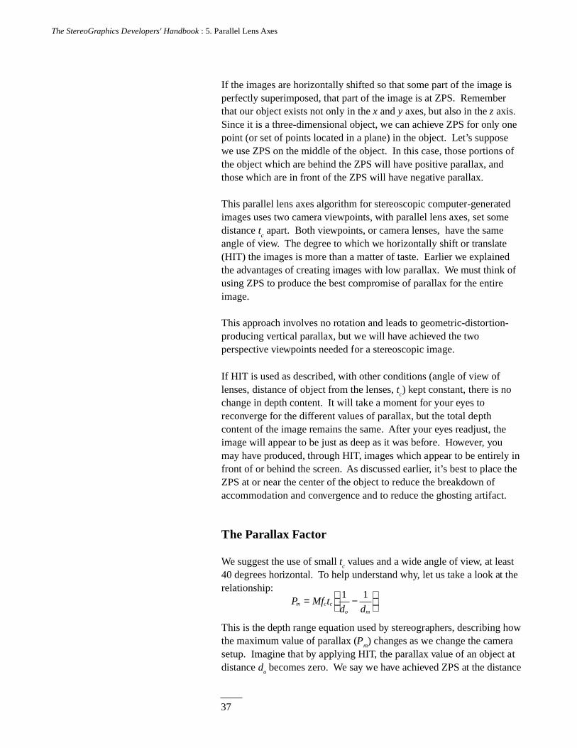
This approach involves no rotation and leads to geometric-distortion-producing vertical parallax, but we will have achieved the twoperspective viewpoints needed for a stereoscopic image.
If HIT is used as described, with other conditions (angle of view oflenses, distance of object from the lenses, tc) kept constant, there is nochange in depth content. It will take a moment for your eyes toreconverge for the different values of parallax, but the total depthcontent of the image remains the same. After your eyes readjust, theimage will appear to be just as deep as it was before. However, youmay have produced, through HIT, images which appear to be entirely infront of or behind the screen. As discussed earlier, it’s best to place theZPS at or near the center of the object to reduce the breakdown ofaccommodation and convergence and to reduce the ghosting artifact.
The Parallax Factor
We suggest the use of small tc values and a wide angle of view, at least40 degrees horizontal. To help understand why, let us take a look at therelationship:
P Mf td d
m c c
o m
= −
1 1
This is the depth range equation used by stereographers, describing howthe maximum value of parallax (Pm) changes as we change the camerasetup. Imagine that by applying HIT, the parallax value of an object atdistance do becomes zero. We say we have achieved ZPS at the distance
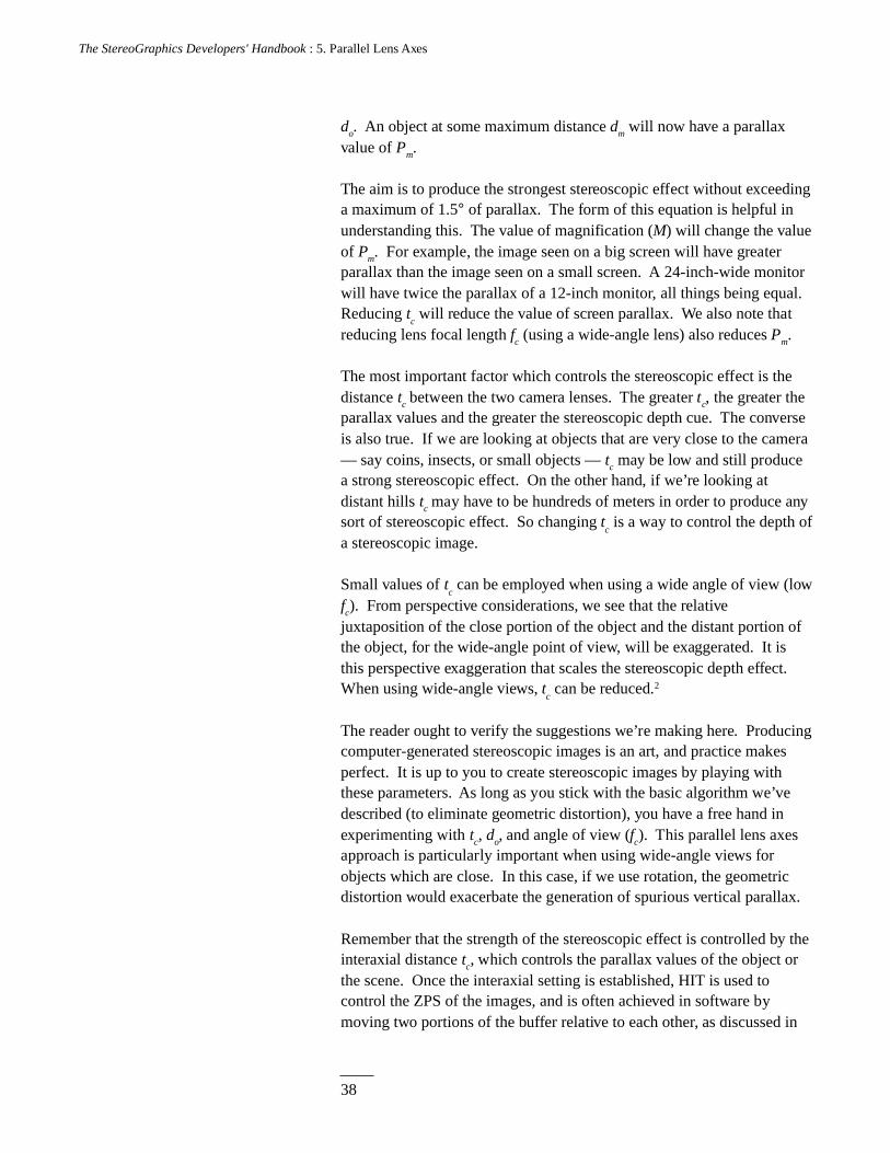
38
The StereoGraphics Developers' Handbook : 5. Parallel Lens Axes
do. An object at some maximum distance dm will now have a parallaxvalue of Pm.
The aim is to produce the strongest stereoscopic effect without exceedinga maximum of 1.5° of parallax. The form of this equation is helpful inunderstanding this. The value of magnification (M) will change the valueof Pm. For example, the image seen on a big screen will have greaterparallax than the image seen on a small screen. A 24-inch-wide monitorwill have twice the parallax of a 12-inch monitor, all things being equal.Reducing t
c will reduce the value of screen parallax. We also note that
reducing lens focal length fc (using a wide-angle lens) also reduces Pm.
The most important factor which controls the stereoscopic effect is thedistance tc between the two camera lenses. The greater tc, the greater theparallax values and the greater the stereoscopic depth cue. The converseis also true. If we are looking at objects that are very close to the camera— say coins, insects, or small objects — tc may be low and still producea strong stereoscopic effect. On the other hand, if we’re looking atdistant hills tc may have to be hundreds of meters in order to produce anysort of stereoscopic effect. So changing t
c is a way to control the depth of
a stereoscopic image.
Small values of tc can be employed when using a wide angle of view (low
fc). From perspective considerations, we see that the relativejuxtaposition of the close portion of the object and the distant portion ofthe object, for the wide-angle point of view, will be exaggerated. It isthis perspective exaggeration that scales the stereoscopic depth effect.When using wide-angle views, t
c can be reduced.2
The reader ought to verify the suggestions we’re making here. Producingcomputer-generated stereoscopic images is an art, and practice makesperfect. It is up to you to create stereoscopic images by playing withthese parameters. As long as you stick with the basic algorithm we’vedescribed (to eliminate geometric distortion), you have a free hand inexperimenting with tc, do, and angle of view (fc). This parallel lens axesapproach is particularly important when using wide-angle views forobjects which are close. In this case, if we use rotation, the geometricdistortion would exacerbate the generation of spurious vertical parallax.
Remember that the strength of the stereoscopic effect is controlled by theinteraxial distance tc, which controls the parallax values of the object orthe scene. Once the interaxial setting is established, HIT is used tocontrol the ZPS of the images, and is often achieved in software bymoving two portions of the buffer relative to each other, as discussed in
39
The StereoGraphics Developers' Handbook : 5. Parallel Lens Axes
the next chapter. The horizontal movement of the left and right images inthe upper and lower portions of the buffer produces HIT, which is used tocontrol ZPS.
In terms of producing user-friendly software, consideration should begiven to the fact that when an image is booted up, it should have theproper ZPS. For a single-object image, a good place for ZPS is themiddle of the object. If this suggestion is not followed, the user will havea difficult time because of the breakdown of accommodation andconvergence, and because of the concomitant crosstalk. It’s important toimplement the ZPS condition in software as a default condition. Inaddition, when changing the size of the image it will also be desirable tomaintain the ZPS, and this can also be implemented in software. Givenour parallel lens axes camera model, when tc is changed the ZPS will alsochange; and it is desirable to implement, in software, a constancy of ZPSeven when tc is varied. This effort will help the user produce a better-quality, easier-to-look-at stereoscopic image.
Windows and Cursors
One important concept for windows is that alphanumerics must appear inboth the left and right fields, and it’s often appropriate for this material tobe at ZPS. Alphanumerics (and the vertical and horizontal lines thatmake up the window) should appear in both the left and right fields in thesame x,y locations. There may be occasions when it is desirable to havewindows which are in CRT or viewer space. This may be appropriatewhen multiple windows are used.
Cursors have the same benefits as they have in the planar display modebut, in addition, for a stereoscopic display they can also provide z-axis-locating with a great degree of accuracy. People who have been active inphotogrammetry use stereoscopic cursors, typically in the form of across, in order to measure height or depth. A cursor appearing in the twosubfields (see the next chapter) in exactly the same location will havezero parallax, but it’s also important to be able to move the cursor in z-space. By moving one or both of the cursors in the left and rightsubfields in the horizontal direction (the x direction), the cursor willappear to be moving in z-space. By counting x pixels, the exact locationof the cursor can be determined. If additional information about thecapture or photography of the image is provided, one will then be able totranslate the counting of x pixels into accurate z measurements. Thedepth sense of binocular stereopsis is exquisitely sensitive, and a skilledoperator will be able to place a cursor to an accuracy of plus-or-minusone pixel.

40
The StereoGraphics Developers' Handbook : 5. Parallel Lens Axes
References
1. Lipton, Lenny, and Meyer, Lhary. A time-multiplexed two-timesvertical frequency stereoscopic video system. International SymposiumDigest, SID 1984, Vol.XV.
2. MacAdam, D.L. Stereoscopic perceptions of size, shape, distance anddirection. SMPTE Journal, 1954, 62:271-93.
41
The StereoGraphics Developers' Handbook: 6. Creating Stereoscopic Software
CreatingStereoscopic Software
C H A P T E R 6
In this chapter we take a more mathematical approach than in the earlychapters of the book. There are two important requirements forconveying stereoscopic three-dimensional images on a single screen:
• Software must perform an offset perspective projection for eacheye, thus simulating what each eye would see if it wereimmersed in the three-dimensional virtual world that thesoftware renderings are based on, and
• The left-eye and right-eye renderings must be formatted to thecomputer display system in a fashion that allows the stereoscopichardware system to separate out left-eye and right-eyeinformation.
This chapter is divided into three parts. The first, creating stereoscopicpairs, deals with the first requirement. The second, the above-belowformat, discusses how to meet the second requirement for CrystalEyeshardware. Finally, the third, the SimulEyes VR format, discusses how tomeet the second requirement for SimulEyes VR hardware that uses theWLC stereoscopic format.
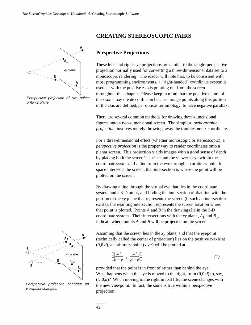
42
The StereoGraphics Developers' Handbook: 6. Creating Stereoscopic Software
Perspective projection changes as viewpoint changes.
A
B
A
A
1
2
B 2
1
2
xy plane
B 1
Perspective projection of two points onto xy plane.
A
B
B 1
xy plane
A1
CREATING STEREOSCOPIC PAIRS
Perspective Projections
These left- and right-eye projections are similar to the single-perspectiveprojection normally used for converting a three-dimensional data set to amonoscopic rendering. The reader will note that, to be consistent withmost programming environments, a “right-handed” coordinate system isused — with the positive z-axis pointing out from the screen —throughout this chapter. Please keep in mind that the positive nature ofthe z-axis may create confusion because image points along this portionof the axis are defined, per optical terminology, to have negative parallax.
There are several common methods for drawing three-dimensionalfigures onto a two-dimensional screen. The simplest, orthographicprojection, involves merely throwing away the troublesome z-coordinate.
For a three-dimensional effect (whether monoscopic or stereoscopic), aperspective projection is the proper way to render coordinates onto aplanar screen. This projection yields images with a good sense of depthby placing both the screen’s surface and the viewer’s eye within thecoordinate system. If a line from the eye through an arbitrary point inspace intersects the screen, that intersection is where the point will beplotted on the screen.
By drawing a line through the virtual eye that lies in the coordinatesystem and a 3-D point, and finding the intersection of that line with theportion of the xy plane that represents the screen (if such an intersectionexists), the resulting intersection represents the screen location wherethat point is plotted. Points A and B in the drawings lie in the 3-Dcoordinate system. Their intersections with the xy plane, A1 and B1,indicate where points A and B will be projected on the screen.
Assuming that the screen lies in the xy plane, and that the eyepoint(technically called the center of projection) lies on the positive z-axis at(0,0,d), an arbitrary point (x,y,z) will be plotted at
xd
d z
yd
d z− −
, (1)
provided that the point is in front of rather than behind the eye.What happens when the eye is moved to the right, from (0,0,d) to, say,(tc,0,d)? When moving to the right in real life, the scene changes withthe new viewpoint. In fact, the same is true within a perspectiveprojection.
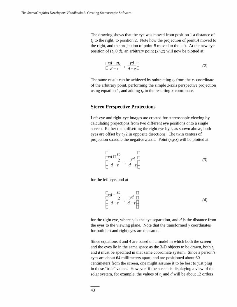
43
The StereoGraphics Developers' Handbook: 6. Creating Stereoscopic Software
The drawing shows that the eye was moved from position 1 a distance oftc to the right, to position 2. Note how the projection of point A moved tothe right, and the projection of point B moved to the left. At the new eyeposition of (tc,0,d), an arbitrary point (x,y,z) will now be plotted at
xd zt
d z
yd
d zc−
− −
, (2)
The same result can be achieved by subtracting tc from the x- coordinateof the arbitrary point, performing the simple z-axis perspective projectionusing equation 1, and adding tc to the resulting x-coordinate.
Stereo Perspective Projections
Left-eye and right-eye images are created for stereoscopic viewing bycalculating projections from two different eye positions onto a singlescreen. Rather than offsetting the right eye by tc as shown above, botheyes are offset by tc/2 in opposite directions. The twin centers ofprojection straddle the negative z-axis. Point (x,y,z) will be plotted at
xdzt
d z
yd
d z
c+
− −
2 , (3)
for the left eye, and at
xdzt
d z
yd
d z
c−
− −
2 , (4)
for the right eye, where tc is the eye separation, and d is the distance fromthe eyes to the viewing plane. Note that the transformed y coordinatesfor both left and right eyes are the same.
Since equations 3 and 4 are based on a model in which both the screenand the eyes lie in the same space as the 3-D objects to be drawn, both tcand d must be specified in that same coordinate system. Since a person’seyes are about 64 millimeters apart, and are positioned about 60centimeters from the screen, one might assume it to be best to just plugin these “true” values. However, if the screen is displaying a view of thesolar system, for example, the values of tc and d will be about 12 orders
44
The StereoGraphics Developers' Handbook: 6. Creating Stereoscopic Software
of magnitude too small. Even if, coincidentally, a 30-centimeter- widescreen is displaying a 30-centimeter-wide scene, it is still not necessarilybest to use the “true” tc and d values. The image might look better with,say, tc set to three centimeters and d set to 50 centimeters. We want to setthe values of tc and d such that the resulting stereoscopic image willconvey a sense of depth, but not so much depth that the image will beunpleasant or uncomfortable to view. Setting a value for tc is discussedin Chapter 3.
Parallax: Too Much of a Good Thing?
In the drawing, Aleft, the left-eye projection of A, lies to the left of theright-eye projection, Aright. If we subtract the x- coordinate of Aleft fromthat of Aright, the resulting parallax will be a positive number, which wecall positive parallax. To the viewer of the projected image, point A willappear to lie behind the surface of the screen. On the other hand, point Bhas negative parallax: the x-coordinate of Bright minus that of Bleft is anegative number. To the viewer, point B will appear in front of thescreen. If a point happens to lie right on the projection plane, the left-and right-eye projections of the point will be the same; they’ll have zeroparallax.
Parallax can also be described in terms of viewing angle. If the right-and left-eye projections of a point appear P centimeters apart, and theuser’s eyes are d centimeters away from the screen, then the parallaxangle is
β = 22
arctanP
d(5)
As discussed on page 12, parallax angle β values exceeding 1.5° tend tomake viewing uncomfortable.
Using other techniques in rendering the image (i.e. hidden-surfaceremoval, shading, depth cueing, etc.) will compliment the depth effect,and allow one to play with the value of βmax. Finally, perceptiondepends on the individual; some people can handle more parallax on ascreen than others.
If βmax is set to 1.5°, you may want to set βmin to -1.5°, thus getting asmuch depth as possible both in front of and behind the surface of thescreen by placing the ZPS in the center of the object. However, it may bebetter to set βmin closer to 0°, or perhaps even at 0°. Why do that? If anobject that appears to sit in front of the screen is cut off by the left or
45
The StereoGraphics Developers' Handbook: 6. Creating Stereoscopic Software
right edge of that screen, the resulting effect of a far object (the screenedge) obscuring a near object (the thing displayed in negative parallax)will interfere with the user’s ability to make sense of the image, asdiscussed on page 17.
Putting the Eyes Where They Belong
In order to obtain a stereoscopic image with enough parallax to convey asense of depth, but not so much parallax that the effect bothers theviewer, we must place the two centers of projection, which represent thetwo eyes, at an appropriate distance from the projection plane (d), andwith an appropriate separation from each other (tc). Also, if we are goingto use negative parallax, the z-coordinate of the plane of zero parallax(zzps) must be selected.
There are two possible approaches for determining the value of zzps(aside from the no-negative-parallax situation, where zzps simply equalszmax):
1) Specify a zzps value in advance, and calculate the eyeseparation based on that, and
2) calculate the zzps value that optimizes use of the parallaxrange from βmin to βmax.
The first method is best where one wants the plane of zero parallax at a z-coordinate value of 0. The second method is best where software mustchoose zzps automatically for a variety of possible coordinate ranges, andit is desirable to make use of the full allowable parallax range from βminto βmax.
Given that
θ = the field-of-view angle ( θ = 40° to 50°),
xmin, xmax = the expected range of world x-coordinate values thatwill be projected onto the screen (the x range specifically refersto the x-coordinate range, on the plane of zero parallax, thatought to appear in the screen viewport),
zmin, zmax = the expected range of world z-coordinate values thatwill be projected onto the screen (this range is likely to be anarrower one than that specified by the far and near clippingplanes),
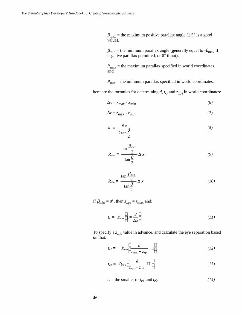
46
The StereoGraphics Developers' Handbook: 6. Creating Stereoscopic Software
βmax = the maximum positive parallax angle (1.5° is a goodvalue),
βmin = the minimum parallax angle (generally equal to -βmax ifnegative parallax permitted, or 0° if not),
Pmax = the maximum parallax specified in world coordinates,and
Pmin = the minimum parallax specified in world coordinates,
here are the formulas for determining d, tc, and zzps in world coordinates:
∆x = xmax - xmin (6)
∆z = zmax - zmin (7)
d x= tan
∆
22θ (8)
P xmax
maxtan
tan=
β
θ2
2
∆ (9)
P xmin
mintan
tan=
β
θ2
2
∆ (10)
If βmin = 0°, then zzps = zmax and:
t Pd
zc = =
max 1∆
(11)
To specify a zzps value in advance, and calculate the eye separation basedon that:
t Pd
z zc1 = −
−−
minmax zps
1 (12)
t Pd
z zc2 =
−+
maxminzps
1 (13)
tc = the smaller of tc1 and tc2 (14)
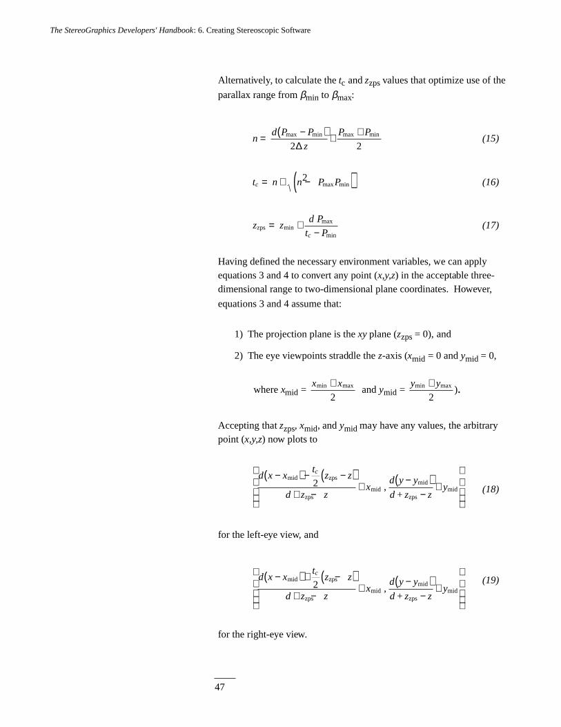
47
The StereoGraphics Developers' Handbook: 6. Creating Stereoscopic Software
Alternatively, to calculate the tc and zzps values that optimize use of the
parallax range from βmin to βmax:
nd P P
z
P P= −( ) + +max min max min
2 2∆(15)
t n n P Pc = + −( )2max min (16)
z zd P
t Pczps = +
−minmax
min(17)
Having defined the necessary environment variables, we can applyequations 3 and 4 to convert any point (x,y,z) in the acceptable three-dimensional range to two-dimensional plane coordinates. However,
equations 3 and 4 assume that:
1) The projection plane is the xy plane (zzps = 0), and
2) The eye viewpoints straddle the z-axis (xmid = 0 and ymid = 0,
where xmid = x xmin max+
2 and ymid =
y ymin max+2
).
Accepting that zzps, xmid, and ymid may have any values, the arbitrarypoint (x,y,z) now plots to
d x xt
z z
d z zx
d y y
d z zy
c−( ) − −( )+ −
+−( )
−+
mid zps
zpsmid
mid
zpsmid
+2 , (18)
for the left-eye view, and
d x xt
z z
d z zx
d y y
d z zy
c−( ) + −( )+ −
+−( )
−+
mid zps
zpsmid
mid
zpsmid
+2 ,
(19)
for the right-eye view.
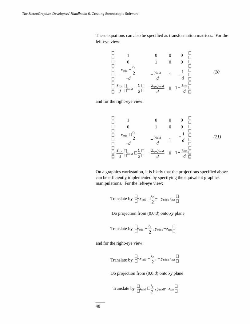
48
The StereoGraphics Developers' Handbook: 6. Creating Stereoscopic Software
These equations can also be specified as transformation matrices. For theleft-eye view:
1
0
0
1
0
0
1 -1d
midmid
zpsmid
zps mid zps
0
0
2
20 1
xt
d
y
d
z
dx
t z y
d
z
d
c
c
−
−−
− −
− −
(20
and for the right-eye view:
1
0
0
1
0
0
1
d
midmid
zpsmid
zps mid zps
0
0
21
20 1
xt
d
y
dd
zx
t z y
d
z
d
c
c
+
−− −
− +
− −
(21)
On a graphics workstation, it is likely that the projections specified abovecan be efficiently implemented by specifying the equivalent graphicsmanipulations. For the left-eye view:
Translate by − + −
x
ty zc
mid mid zps2
, ,
Do projection from (0,0,d) onto xy plane
Translate by xt
y zcmid mid zps− −
2
, ,
and for the right-eye view:
Translate by − − −
x
ty zc
mid mid zps2
, ,
Do projection from (0,0,d) onto xy plane
Translate by xt
y zcmid mid zps+ −
2
, ,
49
The StereoGraphics Developers' Handbook: 6. Creating Stereoscopic Software
Interacting with the User
Some graphics applications give the user more freedom to manipulateimages than others. If the user is able to change the viewingconfiguration, the application needs to make the necessary adjustmentsso that the user will continue to get a high-quality stereoscopic image,with comfortable parallax.
Some examples:
• If an x- or y-coordinate translation occurs, the two centers ofprojection (eyes) need to remain centered about a pointperpendicular to the center of the screen.
• If a z-coordinate translation occurs, the z-coordinate of the ZPS(zzps) will need to be changed.
• If there is a scaling, or some other operation that changes the x, y,or z coordinate ranges, then zzps, as well as the distance from theeyes to zzps (d), and the eye separation (tc) may need to bechanged.
Be sure to test your application to insure that stereoscopic scenes remaincomfortable and effective throughout a user’s interaction with it.
THE ABOVE-BELOW FORMAT
Above-Below Subfields
The standard CrystalEyes system displays stereoscopic images bydoubling the screen refresh rate, thus causing left- and right-eye stereopair elements to overlap. An infrared link synchronizes liquid crystalshutter glasses, allowing the user to perceive true stereoscopic depth.
In order to be compatible with this stereoscopic hardware system,graphics software must run full-screen, using the Above-Belowstereoscopic format. This stereoscopic format consists of mapping avertically-compressed left-eye subfield to the top half of the display, anda vertically-compressed right-eye subfield to the bottom half of thedisplay. This technique is described on page 28.
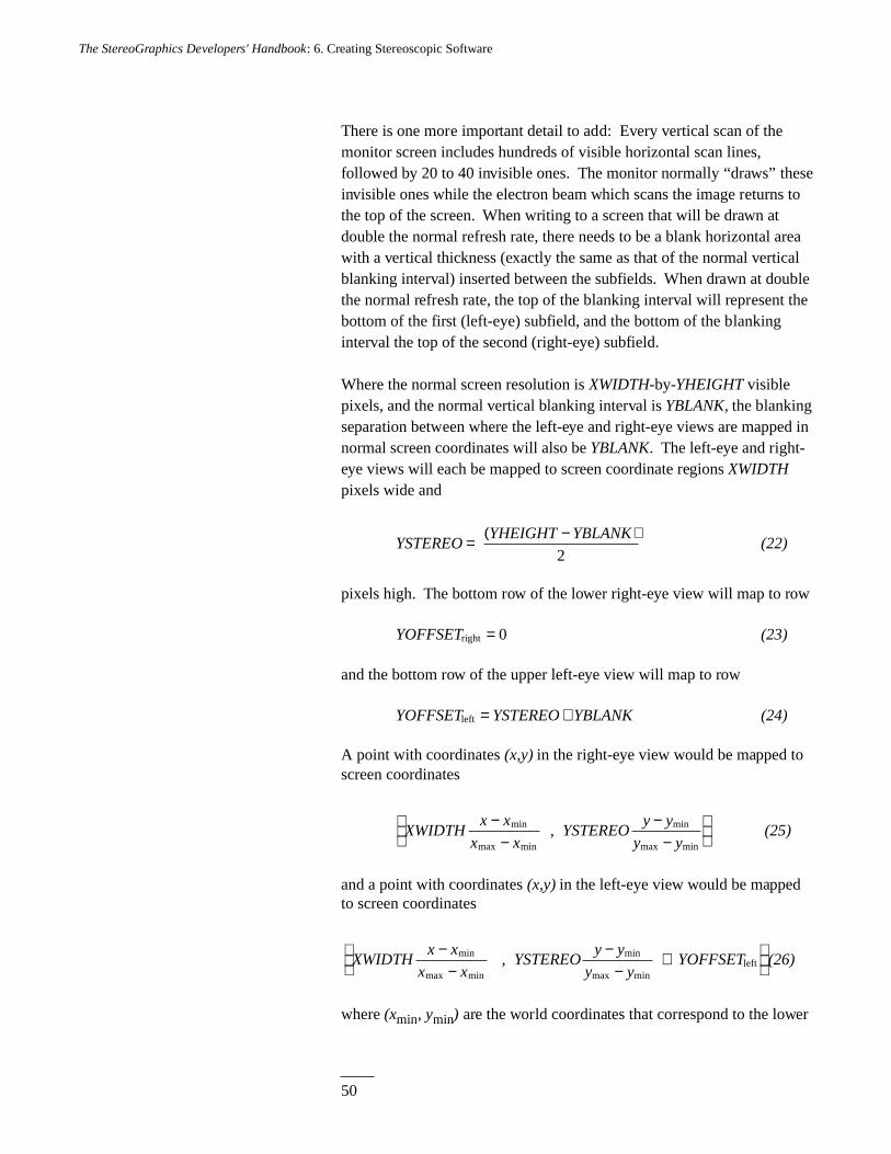
50
The StereoGraphics Developers' Handbook: 6. Creating Stereoscopic Software
There is one more important detail to add: Every vertical scan of themonitor screen includes hundreds of visible horizontal scan lines,followed by 20 to 40 invisible ones. The monitor normally “draws” theseinvisible ones while the electron beam which scans the image returns tothe top of the screen. When writing to a screen that will be drawn atdouble the normal refresh rate, there needs to be a blank horizontal areawith a vertical thickness (exactly the same as that of the normal verticalblanking interval) inserted between the subfields. When drawn at doublethe normal refresh rate, the top of the blanking interval will represent thebottom of the first (left-eye) subfield, and the bottom of the blankinginterval the top of the second (right-eye) subfield.
Where the normal screen resolution is XWIDTH-by-YHEIGHT visiblepixels, and the normal vertical blanking interval is YBLANK, the blankingseparation between where the left-eye and right-eye views are mapped innormal screen coordinates will also be YBLANK. The left-eye and right-eye views will each be mapped to screen coordinate regions XWIDTHpixels wide and
YSTEREOYHEIGHT YBLANK= −( )
2(22)
pixels high. The bottom row of the lower right-eye view will map to row
YOFFSETright = 0 (23)
and the bottom row of the upper left-eye view will map to row
YOFFSET YSTEREO YBLANKleft = + (24)
A point with coordinates (x,y) in the right-eye view would be mapped toscreen coordinates
XWIDTHx x
x xYSTEREO
y y
y y
−−
−−
min
max min
min
max min , (25)
and a point with coordinates (x,y) in the left-eye view would be mappedto screen coordinates
XWIDTHx x
x xYSTEREO
y y
y yYOFFSET
−−
−−
+
min
max min
min
max min , left (26)
where (xmin, ymin) are the world coordinates that correspond to the lower
51
The StereoGraphics Developers' Handbook: 6. Creating Stereoscopic Software
left corner of the viewport, (xmax, ymax) are the world coordinates that
correspond to the upper right corner, and where screen coordinates (0, 0)
represent the lower left corner of the display.
While it is generally easy for the software to find out the resolution(XWIDTH and YHEIGHT) of the current display, depending on the
environment, software will probably need to obtain the value for the
vertical blank interval, YBLANK, indirectly. The “up” and “down” arrowkeys could be used to line up two horizontal line segments to set the
correct value of YBLANK as described on page 23.
Initialization and Interface Issues for Above-Below Stereo
• Because this stereoscopic hardware system alters the sync rate ofthe monitor, converting the entire display to stereo mode, Above-
Below stereoscopic applications must run full-screen.
• Be sure to prompt the user for blank interval information.
Ideally, there should be some kind of calibration functionavailable. Note that the blank interval may be different at
different display resolutions.
• The allowable vertical range of the cursor will need to be
changed from its full range (0 to YHEIGHT - 1) to the range forone eye’s subfield (0 to YSTEREO - 1). This will result in a
cursor that is visible in only one eye, which is preferable to a
cursor that wraps from one eye’s subfield to the other. If theprogramming environment permits two cursors, one could not
only map the cursor for both eyes, but also use parallax toposition the cursor in the z direction.
• Interface elements, such as scroll bars, menus, and dialog boxeseither need to be drawn to both stereoscopic subfields, or they
will be visible in only one eye.
• Just before exiting, be sure to undo any environment changes
made upon initialization.
52
The StereoGraphics Developers' Handbook: 6. Creating Stereoscopic Software
THE SIMULEYES VR STEREOSCOPIC FORMAT
SimulEyes VR White Line Code
The new SimulEyes VR stereoscopic hardware system does not doublethe existing sync rate of the display in order to display stereoscopically.Instead, it changes to a higher sync rate, in a page-swapping or interlacedvideo mode, and the liquid crystal shutter glasses synchronize withalternating screen refreshes.
The simplest way to be compatible with this stereoscopic hardwaresystem is to use the WLC stereoscopic format, placing left-eyeinformation on even-numbered pixel rows (where the top pixel row isrow #0, an even-numbered row), and right-eye information on odd-numbered pixel rows.
This stereoscopic layout must be accompanied by a two-row bitmap, theWLC, filling the display’s bottom two pixel rows. The upper row of thistwo-row bitmap should be pure white for the leftmost 25% of the pixel-row, and pure black for the remainder of that row. The lower row shouldbe pure white for the leftmost 75% of the pixel-row, and pure black forthe remainder of that row. (If these two pixel-rows are switched, with the75% white pixel-row appearing on top, the display’s even-numberedpixel rows will be conveyed to the right eye, and odd-numbered pixel-rows to the left eye, opposite from normal.)
In order for this Interline mapping to be compatible with the stereoscopichardware, the display must be in an interlaced video mode. Switching tointerlace mode may be done manually, but ideally this switch should bedone automatically by the application software. StereoGraphics providessoftware development tools that make it easy to include this functionalityin your application.
Initialization and Interface Issues for SimulEyes VR Stereo
• Unlike Above-Below format stereoscopy, SimulEyes VR formatstereoscopy works well with windowed applicationenvironments, and does not require that applications run full-screen. Application windows may be full-screen, or they may bewindowed with other stereoscopic or non-stereoscopicapplications.
• Note that it is important to place left-eye information on evenpixel rows, and right on odd pixel rows (unless reversed usingthe appropriate variation of the WLC), with respect to the
53
The StereoGraphics Developers' Handbook: 6. Creating Stereoscopic Software
overall display, not with respect to the application window. Forexample, if the application window begins on the display’s pixelrow #101, an even-numbered pixel row of the applicationwindow will actually be an odd-numbered pixel row withrespect to the overall display.
• In order for the stereoscopic hardware system to work, thedisplay needs to be running in an interlace video mode. TheSoftware Development Kit includes library routines to initializethe hardware system for stereoscopy, and to restore the systemwhen the program is about to exit. Consult the SoftwareDevelopment Kit documentation for further details.
• The WLC bitmap must not be confined to a window, but shouldfill the two bottom pixel-rows of the overall display. In addition,care should be taken to insure that the WLC bitmap is notcovered up by other display elements such as scroll-bars,windows, or icons. StereoGraphics provides software tools foreasy implementation of the WLC bitmap in your application.
• Non-stereoscopic interface elements, such as cursors, menus,and dialog boxes should work reasonably well withinstereoscopic applications. Greater visual clarity can be achievedby using larger-than-average cursors and fonts.
• Just before exiting, be sure to undo any environment changesmade upon initialization.
Pseudoscopic Images
Pseudoscopic stereo occurs when the right eye sees the image intendedfor the left eye, and vice versa. This might occur for a number ofreasons-- for example, if your application allows a user to import aninterlined stereoscopic image in which it is unknown whether the top rowis left-eye or right-eye information. In such a case there will be a conflictbetween the stereopsis cue and the monocular cues. Some users will findthe effect disturbing and some won’t seem to notice it.
To avoid this, it is important to keep track of which eye’s view is beingsent to which overall even/odd sets of pixel rows, and be sure to use thecorrect variation of the “white code” when displaying stereoscopicscenes. Pseudoscopic stereo may be corrected by moving the overallstereoscopic image either up or down by one pixel row, or by switchingthe “white code.”
54
The StereoGraphics Developers' Handbook: 6. Creating Stereoscopic Software
The Page-Swap Alternative
An alternative to the Interline stereoscopic format, for use with the sameSimulEyes VR hardware system, is to use page-swapped video display.This method has the advantage of not requiring Interline mapping of thestereoscopic subfields. Page-swapped stereoscopy may be preferable tothe Interline format when using low-resolution video modes that permithigh-speed page-swapping.
Using this method, left- and right-eye subfields should be drawn toseparate video buffers, which then must be page-swapped, with suchvideo page-swaps synchronized to the display’s vertical refresh events.The overall vertical sync rate should be significantly higher than 60 Hz(usually either 70 Hz or 80 Hz) in order for the page-swapped display tonot have an uncomfortable flicker effect.
To implement the “white code” bitmap in a page-swapped stereoscopicapplication, you need to fill in the bottom pixel-row of the left- and right-eye subfields as follows:
• The bottom pixel-row of the left-eye subfield should be purewhite for the left-most 25% of the pixel-row, and pure black forthe remainder of the row.
• The bottom pixel-row of the right-eye subfield should be purewhite for the leftmost 75% of the pixel-row, and pure black forthe remainder of the row.
55
The CrystalEyes Handbook: Glossary
Glossary
Accommodation. Focusing of the eyes.
Accommodation/Convergence Relationship. The habitual relationshipestablished between the focusing and converging of the eyes whenlooking at an object in the visual world.
Binocular. Two eyes. The term “binocular stereopsis” is used in somepsychology books for the depth sense simply described as “stereopsis.”
Conjugate Points. See Corresponding Points.
Convergence. The rotation of the eyes, in the horizontal direction,producing fusion. The term has also been used to describe the movementof left and right image fields or the “toe-in” or rotation of camera heads.
Corresponding Points. The image points of the left and right fieldsreferring to the same point on the object. The distance between thecorresponding points is defined as parallax.
Crosstalk. Incomplete isolation of the left and right image channels.Crosstalk is a physical entity, whereas ghosting is a psychophysicalentity.
56
The CrystalEyes Handbook: Glossary
CRT Space. The region appearing to be within a CRT display screen orbehind the surface of the screen. Images with negative parallax willappear to be in CRT space.
Depth Range. A term that applies most appropriately to stereoscopicimages created with cameras. It is the distance from the ZPS point to thebackground point having parallax which is acceptable in terms of ease ofviewing.
Disparity. The distance between conjugate points on overlaid retinae,sometimes called retinal disparity. The corresponding term for thedisplay screen is parallax.
Extrastereoscopic Cues. Those depth cues appreciated by a personusing only one eye. Also called monocular cues.
Field-Sequential. In the context of electro-stereoscopy, the rapidalternation of left and right perspective viewpoints as fields are writtenon the video display screen.
Fusion. The combination, by the mind, of the left and right images —seen by the left and right eyes — into a single image.
Ghosting. The perception of crosstalk is called ghosting.
HIT. Horizontal image translation. The horizontal shifting of the twoimage fields to change the value of the parallax of corresponding points.The term convergence has been used to denote this concept.
Homologous Points. See Corresponding Points.
Infrared (IR). Invisible radiation used as the communications link forCrystalEyes.
Interaxial Distance. Also interaxial separation. The distance betweencamera lenses’ axes. See t.
Interocular Distance. See Interpupillary Distance.
Interpupillary Distance. Also interpupillary or interocularseparation. The distance between the eyes’ axes. See t.
Monocular Cues. See Extrastereoscopic Cues.
57
The CrystalEyes Handbook: Glossary
Multiplexing. The technique for placing the two images required for anelectro-stereoscopic display within an existing bandwidth.
Parallax. The distance between conjugate points. It may be measuredwith a ruler or, given the distance of an observer from the screen, interms of angular measure. In the latter case, the parallax angle directlyprovides information about disparity.
Planar. Flat. Two-dimensional. A planar image is one contained in atwo-dimensional space, but not necessarily one which appears flat. Itmay have all the depth cues except stereopsis.
Plano-Stereoscopic. A stereoscopic display which is made up of twoplanar images.
Retinal Disparity. See Disparity.
Selection Device. The hardware used to present the appropriate image tothe appropriate eye and to block the unwanted image.
Side-by-Side. The format used by StereoGraphics' video system tosqueeze left and right images into a single video field.
Stereo. Short for stereoscopic. I’ve limited its usage because the term isalso used to denote stereophonic audio.
Stereoplexing. Stereoscopic multiplexing. A means to incorporateinformation for the left and right perspective views into a singleinformation channel without expansion of the bandwidth.
Stereopsis. The binocular depth sense. Literally, “solid seeing.”
Stereoscope. A device for viewing plano-stereoscopic images. It isusually an optical device with twin viewing systems.
Stereoscopy. The art and science of creating images with the depthsense stereopsis.
Surround. The vertical and horizontal edges of the screen immediatelyadjacent to the display.
t. In stereoscopy, t is used to denote the distance between the eyes, calledthe interpupillary or interocular distance. t
c is used to denote the
distance between stereoscopic camera heads’ lens axes.
58
The CrystalEyes Handbook: Glossary
Viewer Space. The region between the display screen surface and theviewer. Images will appear in this region if they have negative parallax.
White Line Code. The last line of the video signal used to tag left andright perspectives and trigger the SimulEyes VR eyewear shutters tosync with the fields.
Window. The stereo window corresponds to the screen surround giventhe algorithms described in these pages.
ZPS. Zero parallax setting. The means used to control screen parallax toplace an object, or a portion of an object or picture, in the plane of thescreen. ZPS may be controlled by HIT. When image points have ZPS,prior terminology would say that they were “converged.” That term isnot used here in that sense, because it may be confused with theconvergence of the eyes, and because the word implies rotation of cameraheads or a software algorithm employing rotation. Such rotationinvariably produces geometric distortion.
___59
Index
Above-and-below technique, 28-29, 33, 49-51Accommodation/convergence relationship, 11, 12, 13, 16-17, 19, 20-21, 23, 25, 37, 39, 55Active eyewear. See EyewearAerial mapping, 19Aerial perspective as a depth cue, 3Afterglow, 12-13, 25Akka, Robert, 41Alphanumerics, 39Alternate field technique. See Time-multiplexed techniqueAngle of view, 25, 36, 37, 44Animation, 33Arrow keys, 23-24Axes of eyes, 11 of lenses, 10, 23
Beta ( $ ) (parallax angle), 44-47Binocular perspectives, 2, 55Blanking intervals, 50-51Brewster, David, 8Broadcast video, 33
Camera model, 36-37Cathode ray tube. See CRTCE-PC eyewear. See CrystalEyes display and eyewearCE2 eyewear. See CrystalEyes display and eyewearColor of the image, 25Composition of stereoscopic images, 15-26Computer animation, 33Computer-generated images, 19, 20-21, 35-40Conjugate image points (corresponding image points), 9, 55
___60
Convergence angle, 22 defined, 55 of the eyes, 7-8, 11, 20, 23, 36, 37 See also Accommodation/convergence relationshipCrimson (SGI computers), 30Crosstalk (ghosting), 12-13, 23, 25, 37, 39, 55CRT phosphor afterglow, 12-13, 25CRT space, 10, 17-18, 20-21, 39, 56CrystalEyes display and eyewear, 2, 8-9, 27-28, 29, 33, 49-51Cursors, 39, 51, 53
d (distance from viewer's eyes to screen), 42-49Databases, three-dimensional, 2Depth cues, 1-5, 15 aerial perspective, 3 conflict of, 17, 18, 21, 53 extrastereoscopic, 3-4, 23, 56 interposition, 3, 18, 21 light and shade, 3 monocular, 3-4, 23, 56 motion parallax, 4 perspective, 4, 19, 20, 21-23, 24 relative size, 3, 23 stereopsis. See Stereoscopic cues textural gradient, 3Depth cuing, 4Depth range, 56Dialog boxes, 51, 53Digital Equipment Corporation (DEC), 30Discomfort when viewing stereoscopic images, 11, 16, 17, 35Disparity. See Retinal disparityDistance (from camera to object photographed). See d and dm o
Distance (from eyes to screen), 42-49Distance (viewer), 19Distortion, 35, 36, 37, 38Divergence, 10Divergent parallax, 10d (maximum distance of object from camera), 37-38m
d (distance of object from camera), 36, 37-38o
DOS games. See GamesDVD applications, 33
___61
Electro-optical shutters, 12, 27, 32Emitter, 27, 29, 30, 33Euclid, 7Extrastereoscopic depth cues. See Depth cuesEye muscles, 11, 16, 35Eyestrain. See Discomfort Eyewear, 27-28, 32, 52 CrystalEyes. See CrystalEyes display and eyewear electro-optical shutters in, 12 passive, 27
f (focal length of lens), 19, 37-38c
Field-of-view angle ( 1 ), 45-46Field-sequential technique. See Time-multiplexed techniqueFilters, neutral-density, 28Fire (photographing in stereo), 23Flicker, 28, 54Focal length of lens. See f c
Focusing of the eyes, 11Fonts, 53Formats for stereo, 27-33Foundations of the Stereoscopic Cinema (Lipton), 26Fusion, 8, 16, 56
Games, 18, 32Ghosting. See CrosstalkGlasses. See EyewearGlitter (of the stereoscopic image), 23Graphics applications, 30, 31, 48-49
Head-mounted display (HMD), 28, 33Hewlett-Packard (HP), 30HIT. See Horizontal image translationHMD. See Head-mounted display Homologous image points, 9, 56Horizontal image translation (HIT), 20-21, 23-24, 35, 36-37,
38-39, 56, 58Horizontal parallax, 10-11
IBM computers, 30, 32Icons, 53Image magnification. See MImage selection techniques, 27Independent Filmmaking (Lipton), 26Infrared emitter. See Emitter
___62
Initialization, 51, 53Inoue, T., 26Interaxial distance ( t ), 10, 12, 23-24, 25, 36, 37-38, 39, c
42-48, 56, 57Interaxial separation. See Interaxial distanceInterface elements, 51, 53Interlace technique. See Time-multiplexed techniqueInterlace video mode, 52, 53Interline stereoscopic format, 52, 54Interocular distance ( t ), 9, 10, 19, 56, 57Interposition as a depth cue. See Depth cuesInterpupillary distance. See Interocular distanceIntrospection, 7-8
Kaufman, Lloyd, 5, 26Kepler, Johannes, 7
Laser disc applications, 33LC shutters, 27Leakage. See CrosstalkLeft and right image fields, congruence of, 10-11Left image field, 10-11Lens axes, 10, 36 parallel, 18, 19Lenses focal length. See f c
long-focal-length (telephoto), 19, 36 short-focal-length (wide-angle), 19, 24, 36Lenticular stereoscope, 8Leonardo da Vinci, 7Light and shade as depth cues, 3Lipton, Lenny, 14, 26, 40Liquid crystal shutters, 27Luster (of the stereoscopic image), 23
M (image magnification), 19, 37-38MacAdam, D.L., 5, 40Menus, 51, 53Meyer, Lhary, 40Mirror stereoscope, 8Molecular modeling, 19, 28Monocular depth cues. See Depth cuesMotion parallax as a depth cue, 4
___63
Negative (crossed) parallax. See ParallaxNTSC equipment and specifications, 29, 31, 33
OEM products, 33Ohzu, H., 26Onyx (SGI computers), 30Orthographic projection, 42Orthostereoscopy, 18-20, 24
P (distance apart of right- and left-eye projections), 44Page-swapping mode, 32, 52, 54PAL equipment and specifications, 31, 33Parallax, 8-10, 11, 12, 13, 16, 17, 24, 56, 57 angle ( $ ), 44-47 divergent parallax, 10 horizontal parallax, 10-11 motion parallax as a depth cue, 4 negative (crossed) parallax, 10, 13, 17-18, 21, 22, 25, 42, 44 P or P (maximum value of parallax), 37-38, 46m max
positive (uncrossed) parallax, 10, 13, 16, 21, 22, 25, 44 vertical parallax, 35, 37, 38 zero parallax, 9, 16, 20-21, 36, 39, 44, 45Parallel lens axes. See Lens axesParallel lens axes algorithm, 20, 25, 35-40Passive eyewear, 27PCs, 29, 31-32, 33Personal computers. See PCsPerspective as a depth cue. See Depth cuesPerspective projections, 42-48Philosophical Transactions of the Royal Society of London , 13Phosphor afterglow. See CRT phosphor afterglowPhotogrammetry, 19, 39Pixels, 30Plane of convergence, 20Plano-stereoscopic image, 2, 11, 57Playback Controller, 31, 33P or (maximum value of parallax). See Parallaxm max
Polarizing eyewear, 27Positive (uncrossed) parallax. See ParallaxPseudoscopic stereo images, 53
___64
RAM, 30Raster, 29, 31Real-time viewing, 31Relative size as a depth cue, 3, 23Retinal disparity, 7, 9, 12, 22, 23, 55Right image field, 10-11Rotation, for creation of stereopairs, 25, 35, 37, 38
Scintillation (of the stereoscopic image), 23Screen surround, 17-18, 21, 22, 25, 57Scroll bars, 51, 53Selection devices. See EyewearSelection techniques for stereoscopic images, 27Shade and light as depth cues, 3 Shutters. See Electro-optical shuttersSID, 40Side-by-side format, 27, 31, 33, 57Sight and Mind: An Introduction to Visual Perception (Kaufman),
5, 26Silicon Graphics (SGI), 30SimulEyes VR product, 2, 8-9, 27, 32, 33, 52-54SMPTE Journal , 5, 40Society for Information Display, 40Society of Motion Picture and Television Engineers. See SMPTESociety of Photo-optical and Instrumentation Engineers. See SPIESoftware, stereoscopic creating, 41-54 standard for, 23Software Development Kit, 53Sparkle (of the stereoscopic image), 23SPIE, 14, 26Spottiswoode, Nigel, 26Spottiswoode, Raymond, 26Stereo pairs, creating, 42-49Stereo-ready computers, 30, 33Stereo window, 17-18, 20, 39, 58Stereoplexing, 57Stereopsis, 7, 8, 9, 15, 57Stereopsis depth cue. See Stereoscopic cuesStereoscope, 7, 8, 11, 12, 27, 57Stereoscopic cues, 8, 21, 22, 23Stereoscopic images, defined, 1, 2Stereoscopy (Valyus), 14Sun Microsystems, 30Surround. See Screen surround
___65
t (interocular distance). See Interocular distancet (interaxial distance). See Interaxial distancec
Telephoto lenses. See Lenses, long-focal-length (telephoto)Textural gradient as a depth cue, 3The Theory of Stereoscopic Transmission... (Spottiswoode &
Spottiswoode), 26Theta ( 1 ) (field-of-view angle), 45-46Three-dimensional databases, 2Time-multiplexed technique for formatting stereoscopic images, 9, 27, 28, 33, 52, 56
V (viewing distance), 19Valyus, N.A., 14VCR recording, 33Vertical parallax. See ParallaxView-Master viewer, 2, 8, 27View/Record box, 31Viewer space, 17, 20-22, 39, 58Virtual reality, 19
Wheatstone, Charles, 13 stereoscope, 7White-Line-Code (WLC) system, 31-32, 33, 52-53, 58 Wide-angle lenses. See Lenses, short-focal-length (wide-angle)Window. See Stereo windowWindowed application environment, 32, 52-53Workstations, 16, 19, 28, 29, 33
z-axis and z coordinates, 36, 37, 39, 42, 45-49, 51Zero parallax. See ParallaxZero parallax setting (ZPS), 9, 11, 12, 13, 20-21, 23, 24, 25,
35, 36-37, 38-39, 44-49, 56, 58ZScreen, 27Zooming, 23ZPS. See Zero parallax setting