Embed Size (px)
Citation preview
Stereo R-CNN based 3D Object Detection for Autonomous Driving
Peiliang Li1, Xiaozhi Chen2, and Shaojie Shen1
1The Hong Kong University of Science and Technology, [email protected], [email protected], [email protected]
Abstract
We propose a 3D object detection method for au-tonomous driving by fully exploiting the sparse and dense,semantic and geometry information in stereo imagery. Ourmethod, called Stereo R-CNN, extends Faster R-CNN forstereo inputs to simultaneously detect and associate ob-ject in left and right images. We add extra branches afterstereo Region Proposal Network (RPN) to predict sparsekeypoints, viewpoints, and object dimensions, which arecombined with 2D left-right boxes to calculate a coarse1
3D object bounding box. We then recover the accurate3D bounding box by a region-based photometric align-ment using left and right RoIs. Our method does not re-quire depth input and 3D position supervision, however,outperforms all existing fully supervised image-based meth-ods. Experiments on the challenging KITTI dataset showthat our method outperforms the state-of-the-art stereo-based method by around 30% AP on both 3D detectionand 3D localization tasks. Code has been released athttps://github.com/HKUST-Aerial-Robotics/Stereo-RCNN.
1. Introduction3D object detection serves as an essential basis of vi-
sual perception, motion prediction, and planning for au-tonomous driving. Currently, most of the 3D object detec-tion methods [5, 23, 31, 13, 18] heavily rely on LiDAR datafor providing accurate depth information in autonomousdriving scenarios. However, LiDAR has the disadvantage ofhigh cost, relatively short perception range (∼100 m), andsparse information (32, 64 lines comparing to >720p im-ages). On the other hand, monocular camera provides alter-native low-cost solutions[3, 21, 27] for 3D object detection.The depth information can be predicted by semantic prop-erties in scenes and object size, etc. However, the inferreddepth cannot guarantee the accuracy, especially for unseenscenes. To this end, we propose a stereo-vision based 3Dobject detection method. Comparing with monocular cam-
1We use the coarse 3D box to represent one with accurate 2D projectionbut not necessarily with accurate 3D position.
era, stereo camera provides more precise depth informationby left-right photometric alignment. Comparing with Li-DAR, stereo camera is low-cost while achieving compara-ble depth accuracy for objects with non-trivial disparities.The perception range of stereo camera depends on the fo-cal length and the baseline. Therefore, stereo vision has thepotential ability to provide larger-range perception by com-bining different stereo modules with different focal lengthand baselines.
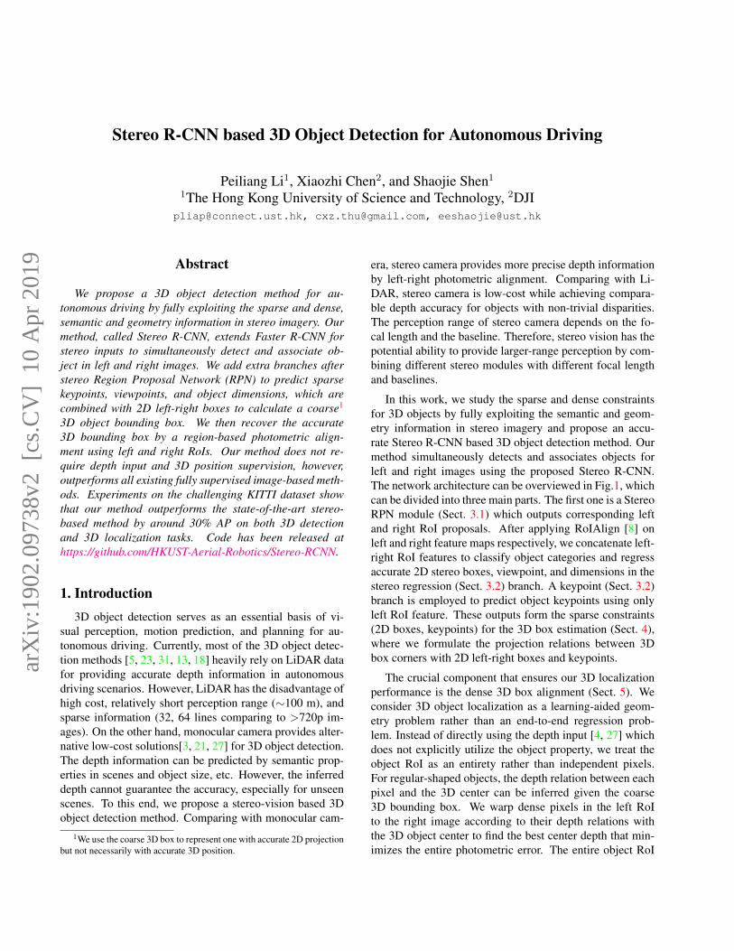
In this work, we study the sparse and dense constraintsfor 3D objects by fully exploiting the semantic and geom-etry information in stereo imagery and propose an accu-rate Stereo R-CNN based 3D object detection method. Ourmethod simultaneously detects and associates objects forleft and right images using the proposed Stereo R-CNN.The network architecture can be overviewed in Fig.1, whichcan be divided into three main parts. The first one is a StereoRPN module (Sect. 3.1) which outputs corresponding leftand right RoI proposals. After applying RoIAlign [8] onleft and right feature maps respectively, we concatenate left-right RoI features to classify object categories and regressaccurate 2D stereo boxes, viewpoint, and dimensions in thestereo regression (Sect. 3.2) branch. A keypoint (Sect. 3.2)branch is employed to predict object keypoints using onlyleft RoI feature. These outputs form the sparse constraints(2D boxes, keypoints) for the 3D box estimation (Sect. 4),where we formulate the projection relations between 3Dbox corners with 2D left-right boxes and keypoints.
The crucial component that ensures our 3D localizationperformance is the dense 3D box alignment (Sect. 5). Weconsider 3D object localization as a learning-aided geom-etry problem rather than an end-to-end regression prob-lem. Instead of directly using the depth input [4, 27] whichdoes not explicitly utilize the object property, we treat theobject RoI as an entirety rather than independent pixels.For regular-shaped objects, the depth relation between eachpixel and the 3D center can be inferred given the coarse3D bounding box. We warp dense pixels in the left RoIto the right image according to their depth relations withthe 3D object center to find the best center depth that min-imizes the entire photometric error. The entire object RoI
arX
iv:1
902.
0973
8v2
[cs
.CV
] 1
0 A
pr 2
019
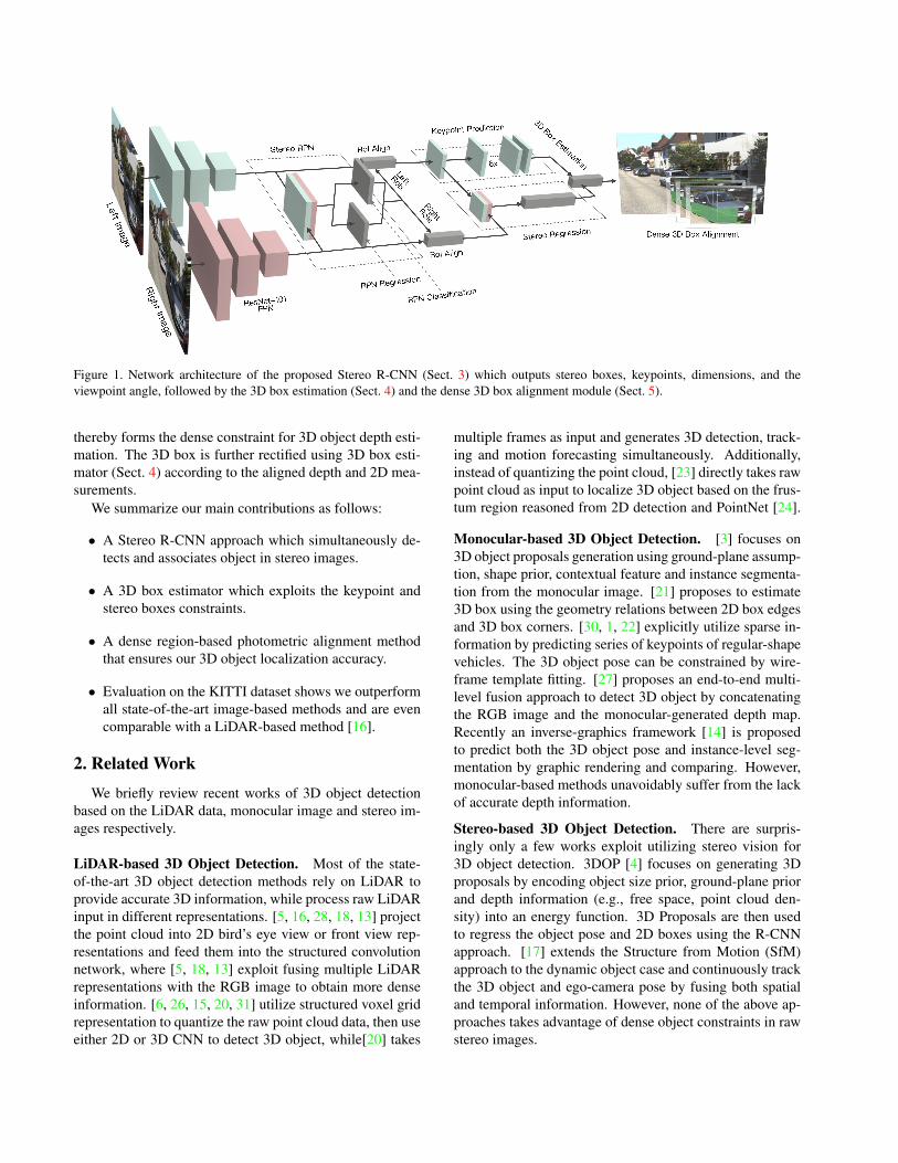
Figure 1. Network architecture of the proposed Stereo R-CNN (Sect. 3) which outputs stereo boxes, keypoints, dimensions, and theviewpoint angle, followed by the 3D box estimation (Sect. 4) and the dense 3D box alignment module (Sect. 5).
thereby forms the dense constraint for 3D object depth esti-mation. The 3D box is further rectified using 3D box esti-mator (Sect. 4) according to the aligned depth and 2D mea-surements.
We summarize our main contributions as follows:
• A Stereo R-CNN approach which simultaneously de-tects and associates object in stereo images.
• A 3D box estimator which exploits the keypoint andstereo boxes constraints.
• A dense region-based photometric alignment methodthat ensures our 3D object localization accuracy.
• Evaluation on the KITTI dataset shows we outperformall state-of-the-art image-based methods and are evencomparable with a LiDAR-based method [16].
2. Related Work
We briefly review recent works of 3D object detectionbased on the LiDAR data, monocular image and stereo im-ages respectively.
LiDAR-based 3D Object Detection. Most of the state-of-the-art 3D object detection methods rely on LiDAR toprovide accurate 3D information, while process raw LiDARinput in different representations. [5, 16, 28, 18, 13] projectthe point cloud into 2D bird’s eye view or front view rep-resentations and feed them into the structured convolutionnetwork, where [5, 18, 13] exploit fusing multiple LiDARrepresentations with the RGB image to obtain more denseinformation. [6, 26, 15, 20, 31] utilize structured voxel gridrepresentation to quantize the raw point cloud data, then useeither 2D or 3D CNN to detect 3D object, while[20] takes
multiple frames as input and generates 3D detection, track-ing and motion forecasting simultaneously. Additionally,instead of quantizing the point cloud, [23] directly takes rawpoint cloud as input to localize 3D object based on the frus-tum region reasoned from 2D detection and PointNet [24].
Monocular-based 3D Object Detection. [3] focuses on3D object proposals generation using ground-plane assump-tion, shape prior, contextual feature and instance segmenta-tion from the monocular image. [21] proposes to estimate3D box using the geometry relations between 2D box edgesand 3D box corners. [30, 1, 22] explicitly utilize sparse in-formation by predicting series of keypoints of regular-shapevehicles. The 3D object pose can be constrained by wire-frame template fitting. [27] proposes an end-to-end multi-level fusion approach to detect 3D object by concatenatingthe RGB image and the monocular-generated depth map.Recently an inverse-graphics framework [14] is proposedto predict both the 3D object pose and instance-level seg-mentation by graphic rendering and comparing. However,monocular-based methods unavoidably suffer from the lackof accurate depth information.
Stereo-based 3D Object Detection. There are surpris-ingly only a few works exploit utilizing stereo vision for3D object detection. 3DOP [4] focuses on generating 3Dproposals by encoding object size prior, ground-plane priorand depth information (e.g., free space, point cloud den-sity) into an energy function. 3D Proposals are then usedto regress the object pose and 2D boxes using the R-CNNapproach. [17] extends the Structure from Motion (SfM)approach to the dynamic object case and continuously trackthe 3D object and ego-camera pose by fusing both spatialand temporal information. However, none of the above ap-proaches takes advantage of dense object constraints in rawstereo images.
&ODVVLILFDWLRQ�7DUJHW
/HIW�5HJUHVV�7DUJHW
5LJKW�5HJUHVV�7DUJHW
Figure 2. Different targets assignment for RPN classification andregression.
3. Stereo R-CNN NetworkIn this section, we describe the Stereo R-CNN network
architecture. Compared with the single frame detector suchas Faster R-CNN [25], Stereo R-CNN can simultaneouslydetect and associate 2D bounding boxes for left and rightimages with minor modifications. We use weight-shareResNet-101 [9] and FPN [19] as our backbone network toextract consistent features on left and right images. Benefitfrom our training target design Fig. 2, there is no additionalcomputation for data association.
3.1. Stereo RPN
Region Proposal Network (RPN) [25] is a sliding-window based foreground detector. After feature extrac-tion, a 3× 3 convolution layer is utilized to reduce channel,followed by two sibling fully-connected layer to classifyobjectness and regress box offsets for each input locationwhich is anchored with pre-define multiple-scale boxes.Similar with FPN [19], we modify origin RPN for pyra-mid features by evaluating anchors on multiple-scale fea-ture maps. The difference is we concatenate left and rightfeature maps at each scale, then we feed the concatenatedfeatures into the stereo RPN network.
The key design enables our simultaneous object detec-tion and association is the different ground-truth (GT) boxassignment for objectness classifier and stereo box regres-sor. As illustrated in Fig. 2, we assign the union of left andright GT boxes (referred as union GT box) as the target forobjectness classification. An anchor is assigned a positivelabel if its Intersection-over-Union (IoU) ratio with one ofunion GT boxes is above 0.7, and a negative label if its IoUwith any of union boxes is below 0.3. Benefit from this de-sign, the positive anchors tend to contain both left and rightobject regions. We calculate offsets of positive anchors re-specting to the left and right GT boxes contained in the tar-get union GT box, then assign offsets to the left and rightregression respectively. There are six regressing terms forthe stereo regressor: [∆u,∆w,∆u′,∆w′,∆v,∆h], wherewe use u, v to denote the horizontal and vertical coordinatesof the 2D box center in image space, w, h for width andheight of the box, and the superscript (·)′ for correspond-ing terms in the right image. Note that we use same v, h
!"
#"
#$!$ %
!"#"
%&
!"
#"
%&
& = 0
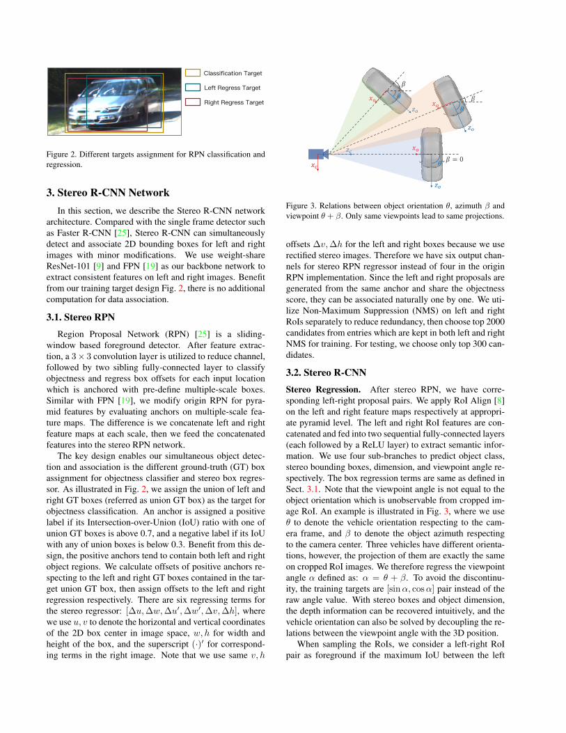
Figure 3. Relations between object orientation θ, azimuth β andviewpoint θ + β. Only same viewpoints lead to same projections.
offsets ∆v,∆h for the left and right boxes because we userectified stereo images. Therefore we have six output chan-nels for stereo RPN regressor instead of four in the originRPN implementation. Since the left and right proposals aregenerated from the same anchor and share the objectnessscore, they can be associated naturally one by one. We uti-lize Non-Maximum Suppression (NMS) on left and rightRoIs separately to reduce redundancy, then choose top 2000candidates from entries which are kept in both left and rightNMS for training. For testing, we choose only top 300 can-didates.
3.2. Stereo R-CNN
Stereo Regression. After stereo RPN, we have corre-sponding left-right proposal pairs. We apply RoI Align [8]on the left and right feature maps respectively at appropri-ate pyramid level. The left and right RoI features are con-catenated and fed into two sequential fully-connected layers(each followed by a ReLU layer) to extract semantic infor-mation. We use four sub-branches to predict object class,stereo bounding boxes, dimension, and viewpoint angle re-spectively. The box regression terms are same as defined inSect. 3.1. Note that the viewpoint angle is not equal to theobject orientation which is unobservable from cropped im-age RoI. An example is illustrated in Fig. 3, where we useθ to denote the vehicle orientation respecting to the cam-era frame, and β to denote the object azimuth respectingto the camera center. Three vehicles have different orienta-tions, however, the projection of them are exactly the sameon cropped RoI images. We therefore regress the viewpointangle α defined as: α = θ + β. To avoid the discontinu-ity, the training targets are [sinα, cosα] pair instead of theraw angle value. With stereo boxes and object dimension,the depth information can be recovered intuitively, and thevehicle orientation can also be solved by decoupling the re-lations between the viewpoint angle with the 3D position.
When sampling the RoIs, we consider a left-right RoIpair as foreground if the maximum IoU between the left
3HUVSHFWLYH.H\SRLQWV
[
]%RXQGDU\.H\SRLQWV
�'�6HPDQWLF�.H\SRLQWV
3HUVSHFWLYH.H\SRLQWV
%RXQGDU\.H\SRLQWV
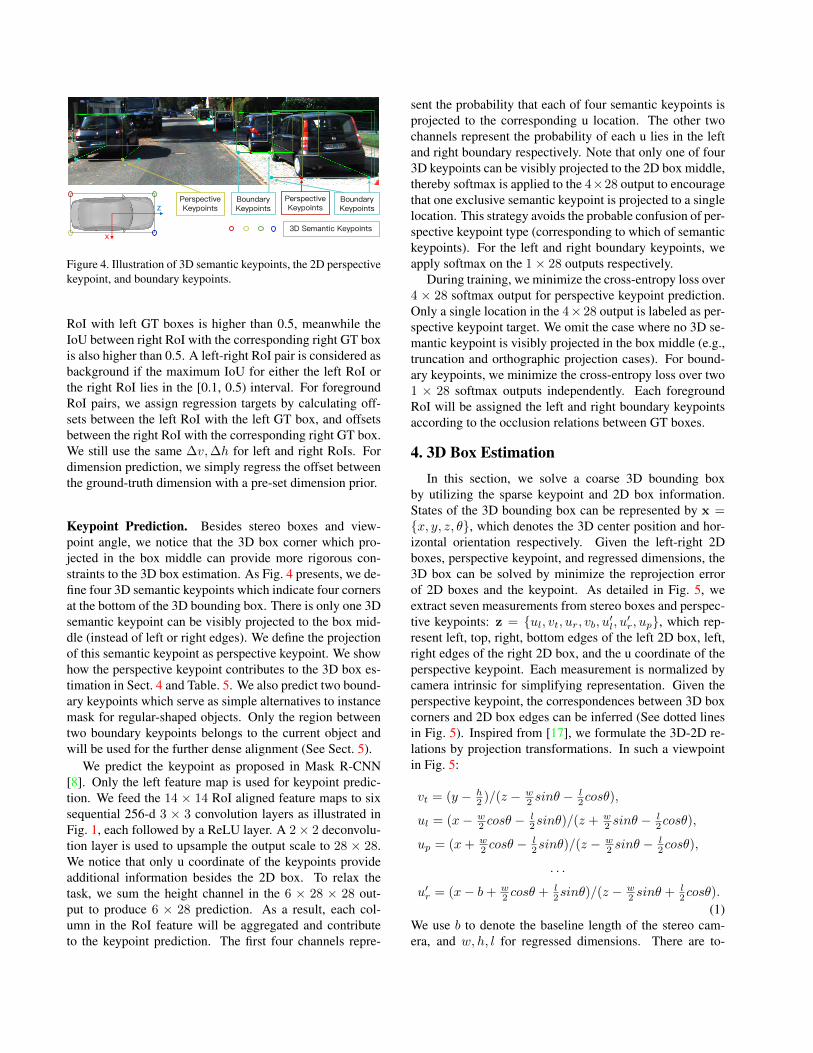
Figure 4. Illustration of 3D semantic keypoints, the 2D perspectivekeypoint, and boundary keypoints.
RoI with left GT boxes is higher than 0.5, meanwhile theIoU between right RoI with the corresponding right GT boxis also higher than 0.5. A left-right RoI pair is considered asbackground if the maximum IoU for either the left RoI orthe right RoI lies in the [0.1, 0.5) interval. For foregroundRoI pairs, we assign regression targets by calculating off-sets between the left RoI with the left GT box, and offsetsbetween the right RoI with the corresponding right GT box.We still use the same ∆v,∆h for left and right RoIs. Fordimension prediction, we simply regress the offset betweenthe ground-truth dimension with a pre-set dimension prior.
Keypoint Prediction. Besides stereo boxes and view-point angle, we notice that the 3D box corner which pro-jected in the box middle can provide more rigorous con-straints to the 3D box estimation. As Fig. 4 presents, we de-fine four 3D semantic keypoints which indicate four cornersat the bottom of the 3D bounding box. There is only one 3Dsemantic keypoint can be visibly projected to the box mid-dle (instead of left or right edges). We define the projectionof this semantic keypoint as perspective keypoint. We showhow the perspective keypoint contributes to the 3D box es-timation in Sect. 4 and Table. 5. We also predict two bound-ary keypoints which serve as simple alternatives to instancemask for regular-shaped objects. Only the region betweentwo boundary keypoints belongs to the current object andwill be used for the further dense alignment (See Sect. 5).
We predict the keypoint as proposed in Mask R-CNN[8]. Only the left feature map is used for keypoint predic-tion. We feed the 14 × 14 RoI aligned feature maps to sixsequential 256-d 3 × 3 convolution layers as illustrated inFig. 1, each followed by a ReLU layer. A 2× 2 deconvolu-tion layer is used to upsample the output scale to 28 × 28.We notice that only u coordinate of the keypoints provideadditional information besides the 2D box. To relax thetask, we sum the height channel in the 6 × 28 × 28 out-put to produce 6 × 28 prediction. As a result, each col-umn in the RoI feature will be aggregated and contributeto the keypoint prediction. The first four channels repre-
sent the probability that each of four semantic keypoints isprojected to the corresponding u location. The other twochannels represent the probability of each u lies in the leftand right boundary respectively. Note that only one of four3D keypoints can be visibly projected to the 2D box middle,thereby softmax is applied to the 4×28 output to encouragethat one exclusive semantic keypoint is projected to a singlelocation. This strategy avoids the probable confusion of per-spective keypoint type (corresponding to which of semantickeypoints). For the left and right boundary keypoints, weapply softmax on the 1× 28 outputs respectively.
During training, we minimize the cross-entropy loss over4 × 28 softmax output for perspective keypoint prediction.Only a single location in the 4× 28 output is labeled as per-spective keypoint target. We omit the case where no 3D se-mantic keypoint is visibly projected in the box middle (e.g.,truncation and orthographic projection cases). For bound-ary keypoints, we minimize the cross-entropy loss over two1 × 28 softmax outputs independently. Each foregroundRoI will be assigned the left and right boundary keypointsaccording to the occlusion relations between GT boxes.
4. 3D Box EstimationIn this section, we solve a coarse 3D bounding box
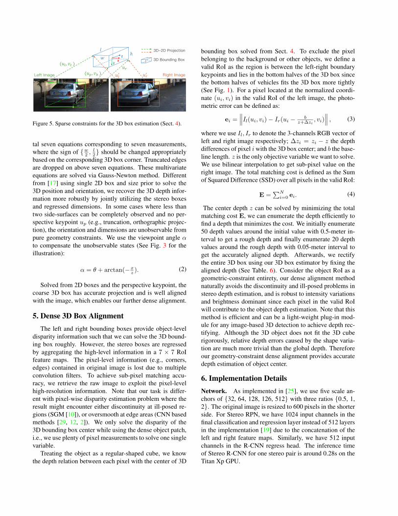
by utilizing the sparse keypoint and 2D box information.States of the 3D bounding box can be represented by x ={x, y, z, θ}, which denotes the 3D center position and hor-izontal orientation respectively. Given the left-right 2Dboxes, perspective keypoint, and regressed dimensions, the3D box can be solved by minimize the reprojection errorof 2D boxes and the keypoint. As detailed in Fig. 5, weextract seven measurements from stereo boxes and perspec-tive keypoints: z = {ul, vt, ur, vb, u′l, u′r, up}, which rep-resent left, top, right, bottom edges of the left 2D box, left,right edges of the right 2D box, and the u coordinate of theperspective keypoint. Each measurement is normalized bycamera intrinsic for simplifying representation. Given theperspective keypoint, the correspondences between 3D boxcorners and 2D box edges can be inferred (See dotted linesin Fig. 5). Inspired from [17], we formulate the 3D-2D re-lations by projection transformations. In such a viewpointin Fig. 5:
vt = (y − h2 )/(z − w
2 sinθ −l2cosθ),
ul = (x− w2 cosθ −
l2sinθ)/(z + w
2 sinθ −l2cosθ),
up = (x+ w2 cosθ −
l2sinθ)/(z −
w2 sinθ −
l2cosθ),
. . .
u′r = (x− b+ w2 cosθ + l
2sinθ)/(z −w2 sinθ + l
2cosθ).
(1)We use b to denote the baseline length of the stereo cam-era, and w, h, l for regressed dimensions. There are to-
xyz
/HIW�,PDJH
("#, %& )
"#( ")(")
("*, %+ ) 5LJKW�,PDJH
�'��'�3URMHFWLRQ
�'�%RXQGLQJ�%R[
,-
ℎ
Figure 5. Sparse constraints for the 3D box estimation (Sect. 4).
tal seven equations corresponding to seven measurements,where the sign of {w2 ,
l2} should be changed appropriately
based on the corresponding 3D box corner. Truncated edgesare dropped on above seven equations. These multivariateequations are solved via Gauss-Newton method. Differentfrom [17] using single 2D box and size prior to solve the3D position and orientation, we recover the 3D depth infor-mation more robustly by jointly utilizing the stereo boxesand regressed dimensions. In some cases where less thantwo side-surfaces can be completely observed and no per-spective keypoint up (e.g., truncation, orthographic projec-tion), the orientation and dimensions are unobservable frompure geometry constraints. We use the viewpoint angle αto compensate the unobservable states (See Fig. 3 for theillustration):
α = θ + arctan(−xz ). (2)
Solved from 2D boxes and the perspective keypoint, thecoarse 3D box has accurate projection and is well alignedwith the image, which enables our further dense alignment.
5. Dense 3D Box AlignmentThe left and right bounding boxes provide object-level
disparity information such that we can solve the 3D bound-ing box roughly. However, the stereo boxes are regressedby aggregating the high-level information in a 7 × 7 RoIfeature maps. The pixel-level information (e.g., corners,edges) contained in original image is lost due to multipleconvolution filters. To achieve sub-pixel matching accu-racy, we retrieve the raw image to exploit the pixel-levelhigh-resolution information. Note that our task is differ-ent with pixel-wise disparity estimation problem where theresult might encounter either discontinuity at ill-posed re-gions (SGM [10]), or oversmooth at edge areas (CNN basedmethods [29, 12, 2]). We only solve the disparity of the3D bounding box center while using the dense object patch,i.e., we use plenty of pixel measurements to solve one singlevariable.
Treating the object as a regular-shaped cube, we knowthe depth relation between each pixel with the center of 3D
bounding box solved from Sect. 4. To exclude the pixelbelonging to the background or other objects, we define avalid RoI as the region is between the left-right boundarykeypoints and lies in the bottom halves of the 3D box sincethe bottom halves of vehicles fits the 3D box more tightly(See Fig. 1). For a pixel located at the normalized coordi-nate (ui, vi) in the valid RoI of the left image, the photo-metric error can be defined as:
ei =∥∥∥Il(ui, vi)− Ir(ui − b
z+∆zi, vi)
∥∥∥ , (3)
where we use Il, Ir to denote the 3-channels RGB vector ofleft and right image respectively; ∆zi = zi − z the depthdifferences of pixel iwith the 3D box center; and b the base-line length. z is the only objective variable we want to solve.We use bilinear interpolation to get sub-pixel value on theright image. The total matching cost is defined as the Sumof Squared Difference (SSD) over all pixels in the valid RoI:
E =∑Ni=0 ei. (4)
The center depth z can be solved by minimizing the totalmatching cost E, we can enumerate the depth efficiently tofind a depth that minimizes the cost. We initially enumerate50 depth values around the initial value with 0.5-meter in-terval to get a rough depth and finally enumerate 20 depthvalues around the rough depth with 0.05-meter interval toget the accurately aligned depth. Afterwards, we rectifythe entire 3D box using our 3D box estimator by fixing thealigned depth (See Table. 6). Consider the object RoI as ageometric-constraint entirety, our dense alignment methodnaturally avoids the discontinuity and ill-posed problems instereo depth estimation, and is robust to intensity variationsand brightness dominant since each pixel in the valid RoIwill contribute to the object depth estimation. Note that thismethod is efficient and can be a light-weight plug-in mod-ule for any image-based 3D detection to achieve depth rec-tifying. Although the 3D object does not fit the 3D cuberigorously, relative depth errors caused by the shape varia-tion are much more trivial than the global depth. Thereforeour geometry-constraint dense alignment provides accuratedepth estimation of object center.
6. Implementation DetailsNetwork. As implemented in [25], we use five scale an-chors of {32, 64, 128, 126, 512} with three ratios {0.5, 1,2}. The original image is resized to 600 pixels in the shorterside. For Stereo RPN, we have 1024 input channels in thefinal classification and regression layer instead of 512 layersin the implementation [19] due to the concatenation of theleft and right feature maps. Similarly, we have 512 inputchannels in the R-CNN regress head. The inference timeof Stereo R-CNN for one stereo pair is around 0.28s on theTitan Xp GPU.
AP2d (IoU=0.7)AR (300 Proposals) Left Right Stereo
Method Left Right Stereo Easy Mode Hard Easy Mode Hard Easy Mode Hard
Faster R-CNN[25] 86.08 - - 98.57 89.01 71.54 - - - - - -Stereo R-CNNmean 85.50 85.56 74.60 90.58 88.42 71.24 90.59 88.47 71.28 90.53 88.24 71.12Stereo R-CNNconcat 86.20 86.27 75.51 98.73 88.48 71.26 98.71 88.50 71.28 98.53 88.27 71.14
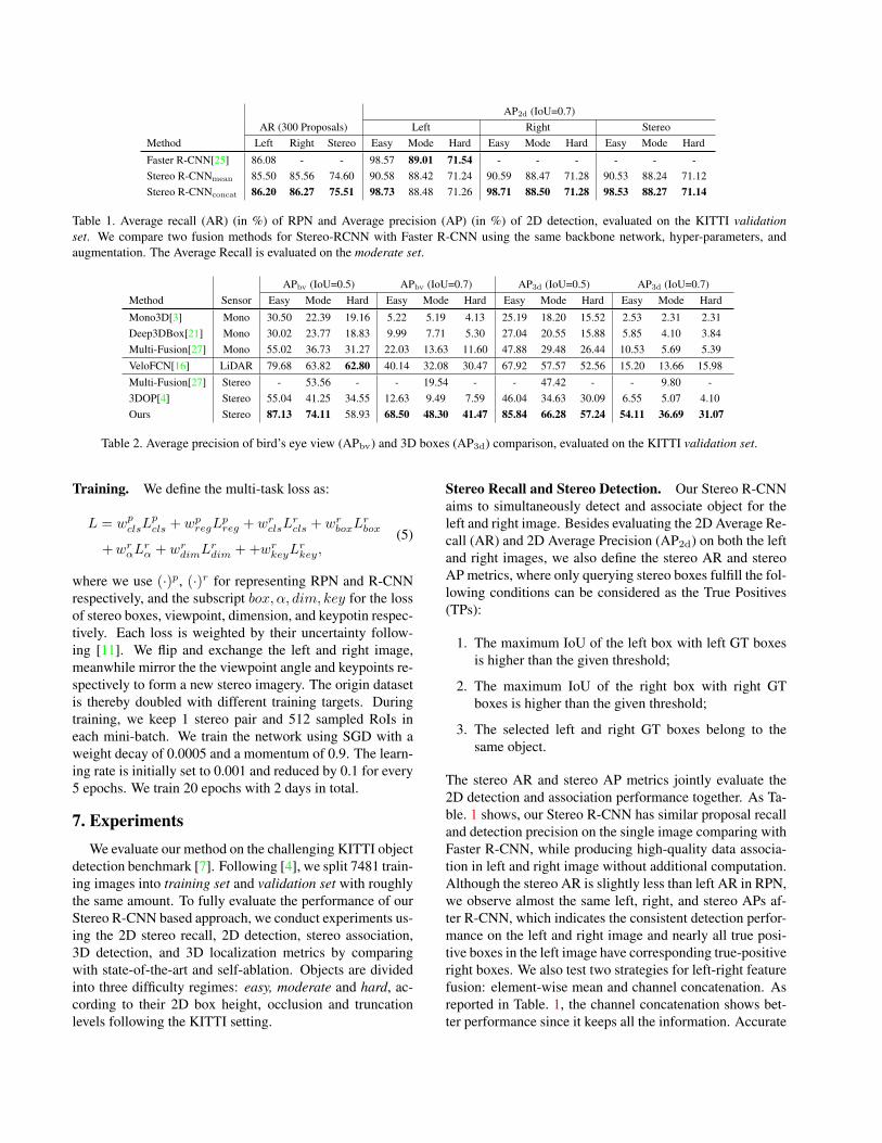
Table 1. Average recall (AR) (in %) of RPN and Average precision (AP) (in %) of 2D detection, evaluated on the KITTI validationset. We compare two fusion methods for Stereo-RCNN with Faster R-CNN using the same backbone network, hyper-parameters, andaugmentation. The Average Recall is evaluated on the moderate set.
APbv (IoU=0.5) APbv (IoU=0.7) AP3d (IoU=0.5) AP3d (IoU=0.7)Method Sensor Easy Mode Hard Easy Mode Hard Easy Mode Hard Easy Mode Hard
Mono3D[3] Mono 30.50 22.39 19.16 5.22 5.19 4.13 25.19 18.20 15.52 2.53 2.31 2.31Deep3DBox[21] Mono 30.02 23.77 18.83 9.99 7.71 5.30 27.04 20.55 15.88 5.85 4.10 3.84Multi-Fusion[27] Mono 55.02 36.73 31.27 22.03 13.63 11.60 47.88 29.48 26.44 10.53 5.69 5.39VeloFCN[16] LiDAR 79.68 63.82 62.80 40.14 32.08 30.47 67.92 57.57 52.56 15.20 13.66 15.98Multi-Fusion[27] Stereo - 53.56 - - 19.54 - - 47.42 - - 9.80 -3DOP[4] Stereo 55.04 41.25 34.55 12.63 9.49 7.59 46.04 34.63 30.09 6.55 5.07 4.10Ours Stereo 87.13 74.11 58.93 68.50 48.30 41.47 85.84 66.28 57.24 54.11 36.69 31.07
Table 2. Average precision of bird’s eye view (APbv) and 3D boxes (AP3d) comparison, evaluated on the KITTI validation set.
Training. We define the multi-task loss as:
L = wpclsLpcls + wpregL
preg + wrclsL
rcls + wrboxL
rbox
+wrαLrα + wrdimL
rdim + +wrkeyL
rkey,
(5)
where we use (·)p, (·)r for representing RPN and R-CNNrespectively, and the subscript box, α, dim, key for the lossof stereo boxes, viewpoint, dimension, and keypotin respec-tively. Each loss is weighted by their uncertainty follow-ing [11]. We flip and exchange the left and right image,meanwhile mirror the the viewpoint angle and keypoints re-spectively to form a new stereo imagery. The origin datasetis thereby doubled with different training targets. Duringtraining, we keep 1 stereo pair and 512 sampled RoIs ineach mini-batch. We train the network using SGD with aweight decay of 0.0005 and a momentum of 0.9. The learn-ing rate is initially set to 0.001 and reduced by 0.1 for every5 epochs. We train 20 epochs with 2 days in total.
7. ExperimentsWe evaluate our method on the challenging KITTI object
detection benchmark [7]. Following [4], we split 7481 train-ing images into training set and validation set with roughlythe same amount. To fully evaluate the performance of ourStereo R-CNN based approach, we conduct experiments us-ing the 2D stereo recall, 2D detection, stereo association,3D detection, and 3D localization metrics by comparingwith state-of-the-art and self-ablation. Objects are dividedinto three difficulty regimes: easy, moderate and hard, ac-cording to their 2D box height, occlusion and truncationlevels following the KITTI setting.
Stereo Recall and Stereo Detection. Our Stereo R-CNNaims to simultaneously detect and associate object for theleft and right image. Besides evaluating the 2D Average Re-call (AR) and 2D Average Precision (AP2d) on both the leftand right images, we also define the stereo AR and stereoAP metrics, where only querying stereo boxes fulfill the fol-lowing conditions can be considered as the True Positives(TPs):
1. The maximum IoU of the left box with left GT boxesis higher than the given threshold;
2. The maximum IoU of the right box with right GTboxes is higher than the given threshold;
3. The selected left and right GT boxes belong to thesame object.
The stereo AR and stereo AP metrics jointly evaluate the2D detection and association performance together. As Ta-ble. 1 shows, our Stereo R-CNN has similar proposal recalland detection precision on the single image comparing withFaster R-CNN, while producing high-quality data associa-tion in left and right image without additional computation.Although the stereo AR is slightly less than left AR in RPN,we observe almost the same left, right, and stereo APs af-ter R-CNN, which indicates the consistent detection perfor-mance on the left and right image and nearly all true posi-tive boxes in the left image have corresponding true-positiveright boxes. We also test two strategies for left-right featurefusion: element-wise mean and channel concatenation. Asreported in Table. 1, the channel concatenation shows bet-ter performance since it keeps all the information. Accurate
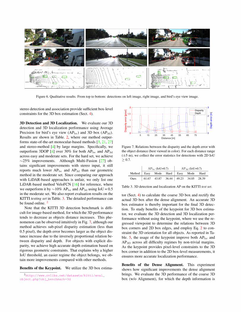
Figure 6. Qualitative results. From top to bottom: detections on left image, right image, and bird’s eye view image.
stereo detection and association provide sufficient box-levelconstraints for the 3D box estimation (Sect. 4).
3D Detection and 3D Localization. We evaluate our 3Ddetection and 3D localization performance using AveragePrecision for bird’s eye view (APbv) and 3D box (AP3d).Results are shown in Table. 2, where our method outper-forms state-of-the-art monocular-based methods [3, 21, 27]and stereo-method [4] by large margins. Specifically, weoutperform 3DOP [4] over 30% for both APbv and AP3d
across easy and moderate sets. For the hard set, we achieve∼25% improvements. Although Multi-Fusion [27] ob-tains significant improvements with stereo input, it stillreports much lower APbv and AP3d than our geometricmethod in the moderate set. Since comparing our approachwith LiDAR-based approaches is unfair, we only list oneLiDAR-based method VeloFCN [16] for reference, wherewe outperform it by∼10% APbv and AP3d using IoU = 0.5in the moderate set. We also report evaluation results on theKITTI testing set in Table. 3. The detailed performance canbe found online. 2
Note that the KITTI 3D detection benchmark is diffi-cult for image-based method, for which the 3D performancetends to decrease as objects distance increases. This phe-nomenon can be observed intuitively in Fig. 7, although ourmethod achieves sub-pixel disparity estimation (less than0.5 pixel), the depth error becomes larger as the object dis-tance increase due to the inversely proportional relation be-tween disparity and depth. For objects with explicit dis-parity, we achieve high accurate depth estimation based onrigorous geometric constraints. That explains why a higherIoU threshold, an easier regime the object belongs, we ob-tain more improvements compared with other methods.
Benefits of the Keypoint. We utilize the 3D box estima-
2http://www.cvlibs.net/datasets/kitti/eval_object.php?obj_benchmark=3d
5 15 25 35 45 55 65 75Distance [m]
0
0.5
1
1.5
2
Dis
parit
y er
ror [
pixe
l]
0
1
2
3
Dep
th e
rror [
m]Disparity
Depth
Figure 7. Relations between the disparity and the depth error withthe object distance (best viewed in color). For each distance range(±5 m), we collect the error statistics for detections with 2D IoU≥ 0.7.
APbv (IoU=0.7) AP3d (IoU=0.7)
Method Easy Mode Hard Easy Mode Hard
Ours 61.67 43.87 36.44 49.23 34.05 28.39
Table 3. 3D detection and localization AP on the KITTI test set.
tor (Sect. 4) to calculate the coarse 3D box and rectify theactual 3D box after the dense alignment. An accurate 3Dbox estimator is thereby important for the final 3D detec-tion. To study benefits of the keypoint for 3D box estima-tor, we evaluate the 3D detection and 3D localization per-formance without using the keypoint, where we use the re-gressed viewpoint to determine the relations between 3Dbox corners and 2D box edges, and employ Eq. 2 to con-straint the 3D orientation for all objects. As reported in Ta-ble. 5, the usage of the keypoint improve both APbv andAP3D across all difficulty regimes by non-trivial margins.As the keypoint provides pixel-level constraints to the 3Dbox corner in addition to the 2D box-level measurements, itensures more accurate localization performance.
Benefits of the Dense Alignment. This experimentshows how significant improvements the dense alignmentbrings. We evaluate the 3D performance of the coarse 3Dbox (w/o Alignment), for which the depth information is
APbv (IoU=0.5) APbv (IoU=0.7) AP3d (IoU=0.5) AP3d (IoU=0.7)Flip Uncert AP0.7
2d Easy Mode Hard Easy Mode Hard Easy Mode Hard Easy Mode Hard
79.03 76.82 64.75 54.72 54.38 36.45 29.74 75.05 60.83 47.69 32.30 21.52 17.61X 79.78 78.24 65.94 56.01 60.93 40.33 33.89 76.87 61.45 48.18 40.22 28.74 23.96
X 88.52 84.89 67.02 57.57 60.93 40.91 34.48 78.76 64.99 55.72 47.53 30.36 25.25X X 88.82 87.13 74.11 58.93 68.50 48.30 41.47 85.84 66.28 57.24 54.11 36.69 31.07
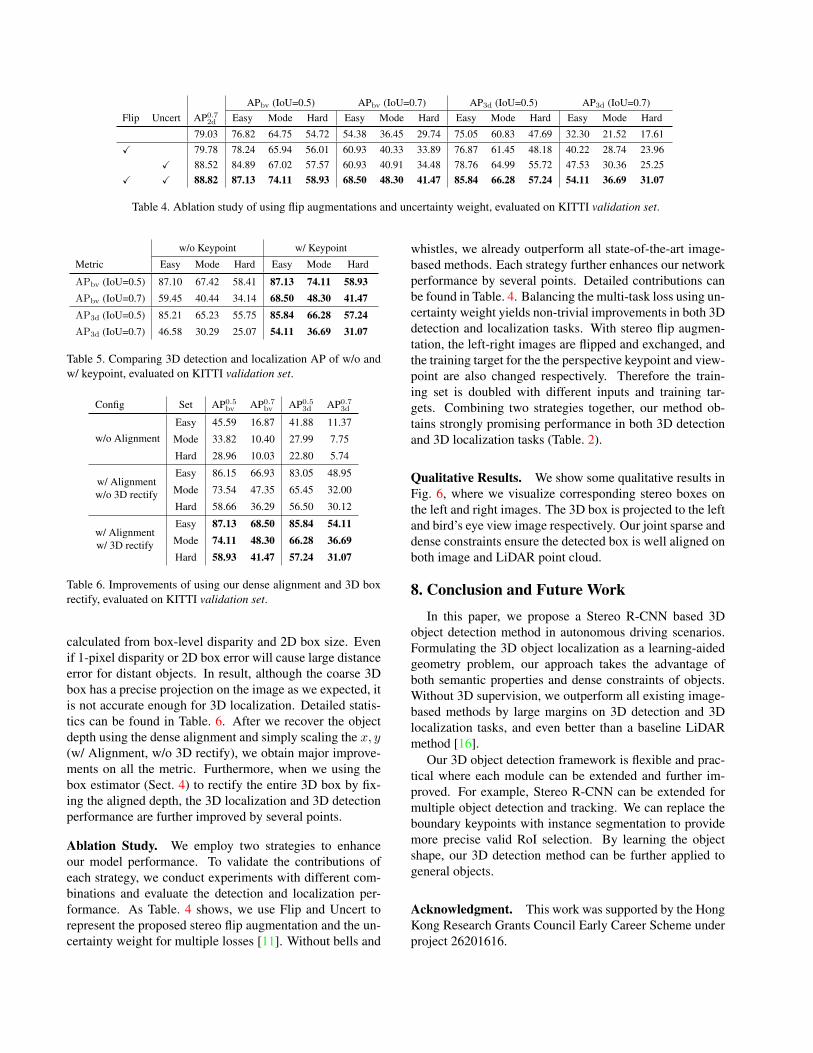
Table 4. Ablation study of using flip augmentations and uncertainty weight, evaluated on KITTI validation set.
w/o Keypoint w/ Keypoint
Metric Easy Mode Hard Easy Mode Hard
APbv (IoU=0.5) 87.10 67.42 58.41 87.13 74.11 58.93APbv (IoU=0.7) 59.45 40.44 34.14 68.50 48.30 41.47AP3d (IoU=0.5) 85.21 65.23 55.75 85.84 66.28 57.24AP3d (IoU=0.7) 46.58 30.29 25.07 54.11 36.69 31.07
Table 5. Comparing 3D detection and localization AP of w/o andw/ keypoint, evaluated on KITTI validation set.
Config Set AP0.5bv AP0.7
bv AP0.53d AP0.7
3d
w/o AlignmentEasy 45.59 16.87 41.88 11.37
Mode 33.82 10.40 27.99 7.75
Hard 28.96 10.03 22.80 5.74
w/ Alignmentw/o 3D rectify
Easy 86.15 66.93 83.05 48.95
Mode 73.54 47.35 65.45 32.00
Hard 58.66 36.29 56.50 30.12
w/ Alignmentw/ 3D rectify
Easy 87.13 68.50 85.84 54.11Mode 74.11 48.30 66.28 36.69Hard 58.93 41.47 57.24 31.07
Table 6. Improvements of using our dense alignment and 3D boxrectify, evaluated on KITTI validation set.
calculated from box-level disparity and 2D box size. Evenif 1-pixel disparity or 2D box error will cause large distanceerror for distant objects. In result, although the coarse 3Dbox has a precise projection on the image as we expected, itis not accurate enough for 3D localization. Detailed statis-tics can be found in Table. 6. After we recover the objectdepth using the dense alignment and simply scaling the x, y(w/ Alignment, w/o 3D rectify), we obtain major improve-ments on all the metric. Furthermore, when we using thebox estimator (Sect. 4) to rectify the entire 3D box by fix-ing the aligned depth, the 3D localization and 3D detectionperformance are further improved by several points.
Ablation Study. We employ two strategies to enhanceour model performance. To validate the contributions ofeach strategy, we conduct experiments with different com-binations and evaluate the detection and localization per-formance. As Table. 4 shows, we use Flip and Uncert torepresent the proposed stereo flip augmentation and the un-certainty weight for multiple losses [11]. Without bells and
whistles, we already outperform all state-of-the-art image-based methods. Each strategy further enhances our networkperformance by several points. Detailed contributions canbe found in Table. 4. Balancing the multi-task loss using un-certainty weight yields non-trivial improvements in both 3Ddetection and localization tasks. With stereo flip augmen-tation, the left-right images are flipped and exchanged, andthe training target for the the perspective keypoint and view-point are also changed respectively. Therefore the train-ing set is doubled with different inputs and training tar-gets. Combining two strategies together, our method ob-tains strongly promising performance in both 3D detectionand 3D localization tasks (Table. 2).
Qualitative Results. We show some qualitative results inFig. 6, where we visualize corresponding stereo boxes onthe left and right images. The 3D box is projected to the leftand bird’s eye view image respectively. Our joint sparse anddense constraints ensure the detected box is well aligned onboth image and LiDAR point cloud.
8. Conclusion and Future WorkIn this paper, we propose a Stereo R-CNN based 3D
object detection method in autonomous driving scenarios.Formulating the 3D object localization as a learning-aidedgeometry problem, our approach takes the advantage ofboth semantic properties and dense constraints of objects.Without 3D supervision, we outperform all existing image-based methods by large margins on 3D detection and 3Dlocalization tasks, and even better than a baseline LiDARmethod [16].
Our 3D object detection framework is flexible and prac-tical where each module can be extended and further im-proved. For example, Stereo R-CNN can be extended formultiple object detection and tracking. We can replace theboundary keypoints with instance segmentation to providemore precise valid RoI selection. By learning the objectshape, our 3D detection method can be further applied togeneral objects.
Acknowledgment. This work was supported by the HongKong Research Grants Council Early Career Scheme underproject 26201616.
References[1] F. Chabot, M. Chaouch, J. Rabarisoa, C. Teuliere, and
T. Chateau. Deep manta: A coarse-to-fine many-task net-work for joint 2d and 3d vehicle analysis from monocularimage. In Proc. IEEE Conf. Comput. Vis. Pattern Recog-nit.(CVPR), pages 2040–2049, 2017.
[2] J.-R. Chang and Y.-S. Chen. Pyramid stereo matching net-work. In Proceedings of the IEEE Conference on ComputerVision and Pattern Recognition, pages 5410–5418, 2018.
[3] X. Chen, K. Kundu, Z. Zhang, H. Ma, S. Fidler, and R. Urta-sun. Monocular 3d object detection for autonomous driving.In European Conference on Computer Vision, pages 2147–2156, 2016.
[4] X. Chen, K. Kundu, Y. Zhu, H. Ma, S. Fidler, and R. Urtasun.3d object proposals using stereo imagery for accurate objectclass detection. In TPAMI, 2017.
[5] X. Chen, H. Ma, J. Wan, B. Li, and T. Xia. Multi-view 3dobject detection network for autonomous driving. In IEEECVPR, volume 1, page 3, 2017.
[6] M. Engelcke, D. Rao, D. Z. Wang, C. H. Tong, and I. Posner.Vote3deep: Fast object detection in 3d point clouds usingefficient convolutional neural networks. In Robotics and Au-tomation (ICRA), 2017 IEEE International Conference on,pages 1355–1361. IEEE, 2017.
[7] A. Geiger, P. Lenz, and R. Urtasun. Are we ready for au-tonomous driving? the kitti vision benchmark suite. In Com-puter Vision and Pattern Recognition (CVPR), 2012 IEEEConference on, pages 3354–3361. IEEE, 2012.
[8] K. He, G. Gkioxari, P. Dollar, and R. Girshick. Mask r-cnn.In Computer Vision (ICCV), 2017 IEEE International Con-ference on, pages 2980–2988. IEEE, 2017.
[9] K. He, X. Zhang, S. Ren, and J. Sun. Deep residual learn-ing for image recognition. In Proceedings of the IEEE con-ference on computer vision and pattern recognition, pages770–778, 2016.
[10] H. Hirschmuller. Stereo processing by semiglobal matchingand mutual information. IEEE Transactions on pattern anal-ysis and machine intelligence, 30(2):328–341, 2008.
[11] A. Kendall, Y. Gal, and R. Cipolla. Multi-task learning usinguncertainty to weigh losses for scene geometry and seman-tics. In Proceedings of the IEEE Conference on ComputerVision and Pattern Recognition (CVPR), 2017.
[12] A. Kendall, H. Martirosyan, S. Dasgupta, P. Henry,R. Kennedy, A. Bachrach, and A. Bry. End-to-end learningof geometry and context for deep stereo regression. CoRR,vol. abs/1703.04309, 2017.
[13] J. Ku, M. Mozifian, J. Lee, A. Harakeh, and S. Waslander.Joint 3d proposal generation and object detection from viewaggregation. arXiv preprint arXiv:1712.02294, 2017.
[14] A. Kundu, Y. Li, and J. M. Rehg. 3d-rcnn: Instance-level3d object reconstruction via render-and-compare. In Pro-ceedings of the IEEE Conference on Computer Vision andPattern Recognition, pages 3559–3568, 2018.
[15] B. Li. 3d fully convolutional network for vehicle detection inpoint cloud. In Intelligent Robots and Systems (IROS), 2017IEEE/RSJ International Conference on, pages 1513–1518.IEEE, 2017.
[16] B. Li, T. Zhang, and T. Xia. Vehicle detection from 3d lidarusing fully convolutional network. In Robotics: Science andSystems, 2016.
[17] P. Li, T. Qin, and S. Shen. Stereo vision-based semantic 3dobject and ego-motion tracking for autonomous driving. InEuropean Conference on Computer Vision, pages 664–679.Springer, 2018.
[18] M. Liang, B. Yang, S. Wang, and R. Urtasun. Deep continu-ous fusion for multi-sensor 3d object detection. In Proceed-ings of the IEEE Conference on Computer Vision and PatternRecognition, pages 663–678, 2018.
[19] T.-Y. Lin, P. Dollar, R. B. Girshick, K. He, B. Hariharan, andS. J. Belongie. Feature pyramid networks for object detec-tion. In CVPR, volume 1, page 4, 2017.
[20] W. Luo, B. Yang, and R. Urtasun. Fast and furious: Realtime end-to-end 3d detection, tracking and motion forecast-ing with a single convolutional net. In Proceedings of theIEEE Conference on Computer Vision and Pattern Recogni-tion, pages 3569–3577, 2018.
[21] A. Mousavian, D. Anguelov, J. Flynn, and J. Kosecka. 3dbounding box estimation using deep learning and geometry.In Computer Vision and Pattern Recognition (CVPR), 2017IEEE Conference on, pages 5632–5640. IEEE, 2017.
[22] J. K. Murthy, G. S. Krishna, F. Chhaya, and K. M. Krishna.Reconstructing vehicles from a single image: Shape priorsfor road scene understanding. In 2017 IEEE InternationalConference on Robotics and Automation (ICRA), pages 724–731. IEEE, 2017.
[23] C. R. Qi, W. Liu, C. Wu, H. Su, and L. J. Guibas. Frus-tum pointnets for 3d object detection from rgb-d data. arXivpreprint arXiv:1711.08488, 2017.
[24] C. R. Qi, H. Su, K. Mo, and L. J. Guibas. Pointnet: Deeplearning on point sets for 3d classification and segmentation.Proc. Computer Vision and Pattern Recognition (CVPR),IEEE, 1(2):4, 2017.
[25] S. Ren, K. He, R. Girshick, and J. Sun. Faster r-cnn: Towardsreal-time object detection with region proposal networks. InAdvances in neural information processing systems, pages91–99, 2015.
[26] D. Z. Wang and I. Posner. Voting for voting in online pointcloud object detection. In Robotics: Science and Systems,volume 1, 2015.
[27] B. Xu and Z. Chen. Multi-level fusion based 3d object de-tection from monocular images. In IEEE CVPR, 2018.
[28] B. Yang, W. Luo, and R. Urtasun. Pixor: Real-time 3d ob-ject detection from point clouds. In Proceedings of the IEEEConference on Computer Vision and Pattern Recognition,pages 7652–7660, 2018.
[29] J. Zbontar and Y. LeCun. Stereo matching by training a con-volutional neural network to compare image patches. Jour-nal of Machine Learning Research, 17(1-32):2, 2016.
[30] M. Zeeshan Zia, M. Stark, and K. Schindler. Are cars just 3dboxes?-jointly estimating the 3d shape of multiple objects.In Proceedings of the IEEE Conference on Computer Visionand Pattern Recognition, pages 3678–3685, 2014.
[31] Y. Zhou and O. Tuzel. Voxelnet: End-to-end learningfor point cloud based 3d object detection. arXiv preprintarXiv:1711.06396, 2017.