Embed Size (px)
Citation preview
17/5/2009
1
Stereo ImagingStereo Imaging
Introduction
Example of Human VisionPerception of Depth from Left and right eye imagesDifference in relative position of object in left and right eyes.Depth information in the 2 views??Depth information in the 2 views??
Saurav Basu

17/5/2009
2
Stereopsis
Retinal disparityRetinal disparityp yp y– The horizontal distance between the corresponding left and right image points of the superimposed retinal images.
– The disparity is zero if the eyes are converged.
Stereopsis– The sense of depth combined from two different perspective views by the mind.
The Stereo Problem
– The stereo problem is usually broken in to two subproblemstwo subproblems•Extraction of Depth information from Stereo Pairs
•Use of depth data to visualize the world scene in 3‐dimensions by a suitable projection techniqueprojection technique.
Saurav Basu
17/5/2009
3
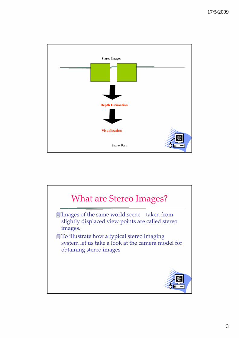
Stereo Images
Depth Estimation
Visualization
Saurav Basu
What are Stereo Images?
Images of the same world scene taken from slightly displaced view points are called stereoslightly displaced view points are called stereo images.To illustrate how a typical stereo imaging system let us take a look at the camera model for obtaining stereo images
17/5/2009
4
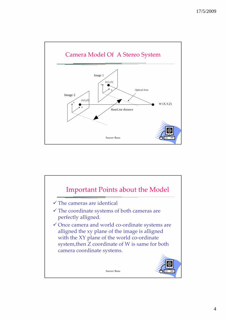
Camera Model Of A Stereo System
Image 1
Image 2
Image 1
W (X,Y,Z)
BaseLine distance
y
x
x
y
(x2,y2)
(x1,y1)
Optical Axis
BaseLine distance
Saurav Basu
Important Points about the Model
The cameras are identicalTh di t t f b thThe coordinate systems of both cameras are perfectly alligned.Once camera and world co‐ordinate systems are alligned the xy plane of the image is allignedwith the XY plane of the world co‐ordinate system then Z coordinate of W is same for bothsystem,then Z coordinate of W is same for both camera coordinate systems.
Saurav Basu
17/5/2009
5
Relating Depth with Image Coordinates
X
(x1,y1) Z - λZ
W (X,Y,Z)Origin Of
World Coordinate
B
λ
Image 1
Z λ
System λ
Image 2(x2,y2)
Saurav Basu
By Similar Triangles:
)( 11
1 −= λλ
ZxX
)(
)()(
)(
21
22
111
1
21
12
22
2
−=−⇒
−=+⇒−=⇒
==+=
−=
λλ
λλ
λλ
λλ
λ
xxBZ
ZxBXZxX
ZZZBXX
ZxX
Disparity x2- x1where
Disparity
1
KB Depth, - Z
21
21
=
⇒−
=⇒
==
α
λλ
Depthxx
KDepth
Putxx
Saurav Basu

17/5/2009
6
Thus Depth is inversely proportional to (x1
Important Result
Thus Depth is inversely proportional to (x1‐x2) where x1 and x2 are pixel coordinates of the same world point when projected on the stereo image planes.(x1‐ x2) is called the DISPARITY The problem of finding x1 and x2 in theThe problem of finding x1 and x2 in the stereo pairs is done by a stereo matching technique.
Saurav Basu
Stereo Matching
– The goal of stereo matching algorithms is to find matching locations in the left and rightfind matching locations in the left and right images .
– Specifically find the coordinates of the pixel on the left and right images which correspond to the same world point. It is also called the correspondence problem– It is also called the correspondence problem.
Saurav Basu
17/5/2009
7
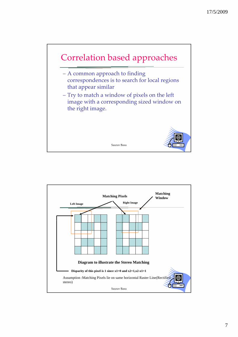
Correlation based approaches
– A common approach to finding correspondences is to search for local regionscorrespondences is to search for local regions that appear similar
– Try to match a window of pixels on the left image with a corresponding sized window on the right image.
Saurav Basu
Matching PixelsMatching Window
Left Image Right Image
Diagram to illustrate the Stereo Matching
Assumption :Matching Pixels lie on same horizontal Raster Line(Rectified stereo)
Disparity of this pixel is 1 since x1=0 and x2=1,x2-x1=1
Saurav Basu

17/5/2009
8
The SSD and SAD are commonly used correlation functions
SSD:Sum of Squared Deviations
2)),(),(()),(),,(( ydxIyxIydxIyxI rlrl +−=+ψ
),(),()),(),,(( ydxIyxIydxIyxI rlrl +−=+ψ
q
SAD:Sum of Absolute Differences
Saurav Basu
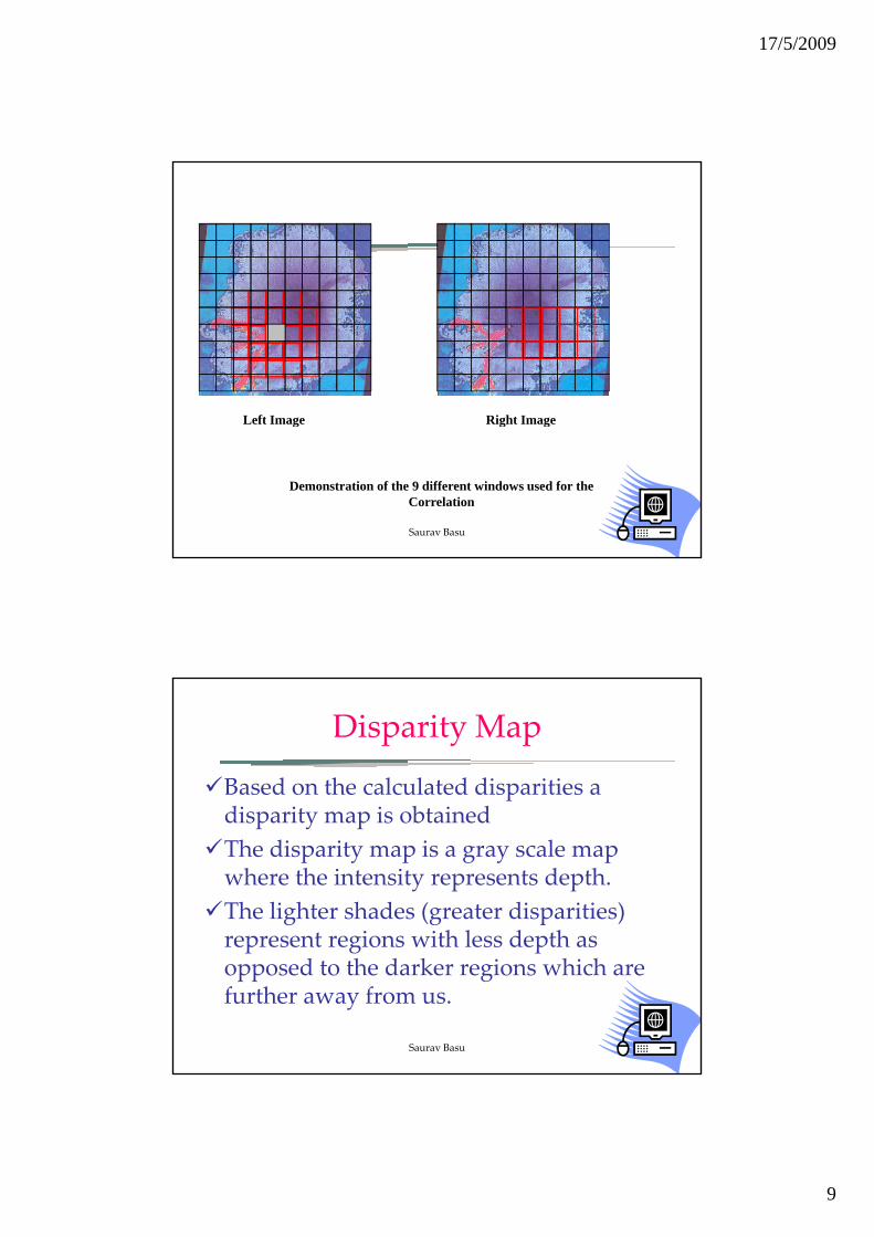
The Multi Window Algorithm
In this algorithm technique 9 different i d d f l l tiwindows are used for calculating
disparity of a single pixel.The window which gives the maximum correlation is used for disparity calculations.a u a io
Saurav Basu
17/5/2009
9
Left Image Right Imageg g g
Demonstration of the 9 different windows used for the Correlation
Saurav Basu
Disparity Map
Based on the calculated disparities a di it i bt i ddisparity map is obtainedThe disparity map is a gray scale map where the intensity represents depth.The lighter shades (greater disparities) represent regions with less depth asrepresent regions with less depth as opposed to the darker regions which are further away from us.
Saurav Basu
17/5/2009
10
Visualization
Visualization is the process by which we th d th ti t f th tuse the depth estimates from the stereo
matching to build projections .3‐D information can be represented in many ways :
‐Orthographic projectionsO og ap i p oje io‐Perspective Projections
Saurav Basu
Perspective Projections
Perspective projections allow a more li ti i li ti f ldrealistic visualization of a world scene
The visual effect of perspective projections is similar to the human visual system and photographic systems.Hence perspective projection of the 3‐dHence perspective projection of the 3‐d data was implemented for the stereo pairs.
Saurav Basu

17/5/2009
11
A
B
•In Perspective projections the projectors are of finite length and converge at a pointA’
B’ Projection Plane
converge at a point called the center of projection.
•In perspective projection size of an object is
Center Of Projection
inversely proportional to its distance from ooint of projection
Projectors
V
(Umax,Vmax)VUP
Window
CW
U
(Umin,Vmin)
VPN
VRP
VIEW PLANE
N
CW
Center of Projection
THE 3-D VIEWING REFERENCE COORDINATE SYSTEM
DOP
Saurav Basu

17/5/2009
12
Specifying a 3‐D View
To specify a 3‐d view we need to specify a projection plane and a center of Projection:projection plane and a center of Projection: The Projection plane specified by 1. A point on the plane called the
View Reference Point (VRP)2. The normal to the view plane,i.e.
Vi Pl N l (VPN)View Plane Normal (VPN)
Saurav Basu
We define a VRC (View Reference Coordinate system) on the projection plane with u v and n being
Specifying a 3‐D View
system) on the projection plane with u,v,and n being its 3 axes forming a right handed coordinate system The origin of the VRC system is the VRPThe VPN defines the ‘n’ axis of the VRC systemA View Up Vector (VUP) determines the ‘v’ axis of the VRC system. The projection of the VUP parallel t th i l i i id t ith th ‘ ’ ito the view plane is coincident with the ‘v’ axis.The ‘u’ axis direction is defined such that the ‘u’,’v’ and ‘n’ form a right handed coordinate system.
Saurav Basu
17/5/2009
13
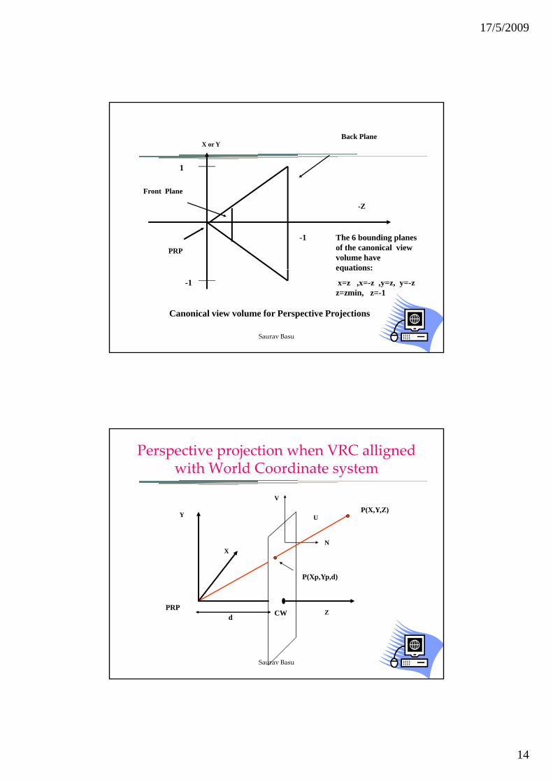
A view Window on the view plane is defined ,projections
Specifying a 3‐D View
p ,p jlying outside the view window are not displayed .The coordinates (Umin,Vmin) and (Umax,Vmax) define this window. The center of projection Projection Reference Point(PRP).
Saurav Basu
The semi infinite pyramid formed by the PRP d th j t i th h
Specifying a 3‐D View
PRP and the projectors passing through the corners of the view window form a view volume.A Canonical view volume is one where the VRC system is alligned with the World e y e i a ig e i e oCoordinate system.
Saurav Basu
17/5/2009
14
X or YBack Plane
1
Front Plane
-1
-Z
The 6 bounding planes of the canonical view volume have equations:
PRP
-1
Canonical view volume for Perspective Projections
equations:
x=z ,x=-z ,y=z, y=-z z=zmin, z=-1
Saurav Basu
Perspective projection when VRC alligned with World Coordinate system
V
P(X,Y,Z)Y
X
U
N
P(Xp,Yp,d)
P(X,Y,Z)
Zd
PRPCW
Saurav Basu
17/5/2009
15
d Zd
ZYY
dZXX
TrianglesSimilar From
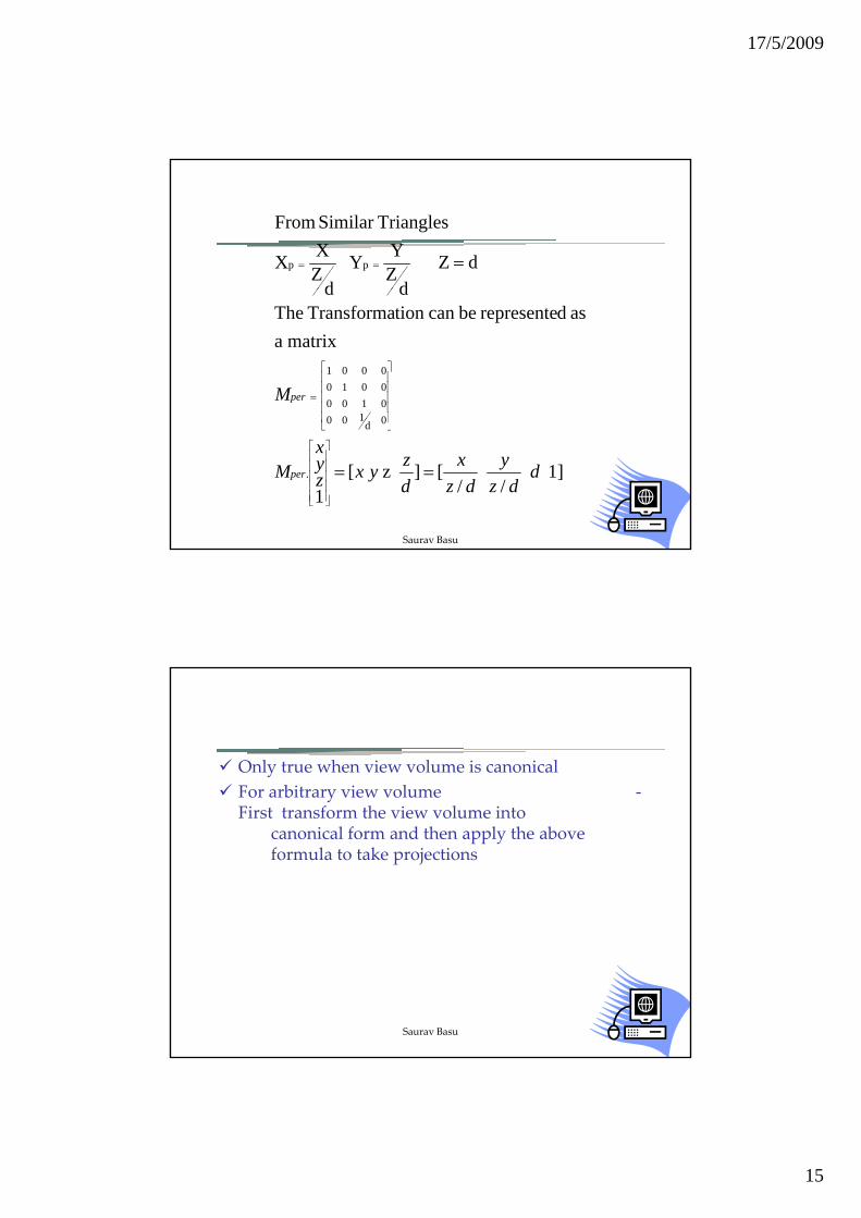
pp ===
matrix a as drepresente becan tion Transforma The
dd
0100010000100001
Mper
⎥⎥⎥⎥⎥
⎦
⎤
⎢⎢⎢⎢⎢
⎣
⎡
=
1] /
/
[] z [1
.
0d100
ddz
ydz
xdzyxz
yx
Mper ==⎥⎥⎥⎥⎥
⎦
⎤
⎢⎢⎢⎢⎢
⎣
⎡
⎥⎦
⎢⎣
Saurav Basu
Only true when view volume is canonicalFor arbitrary view volume ‐For arbitrary view volume First transform the view volume into
canonical form and then apply the above formula to take projections
Saurav Basu
17/5/2009
16
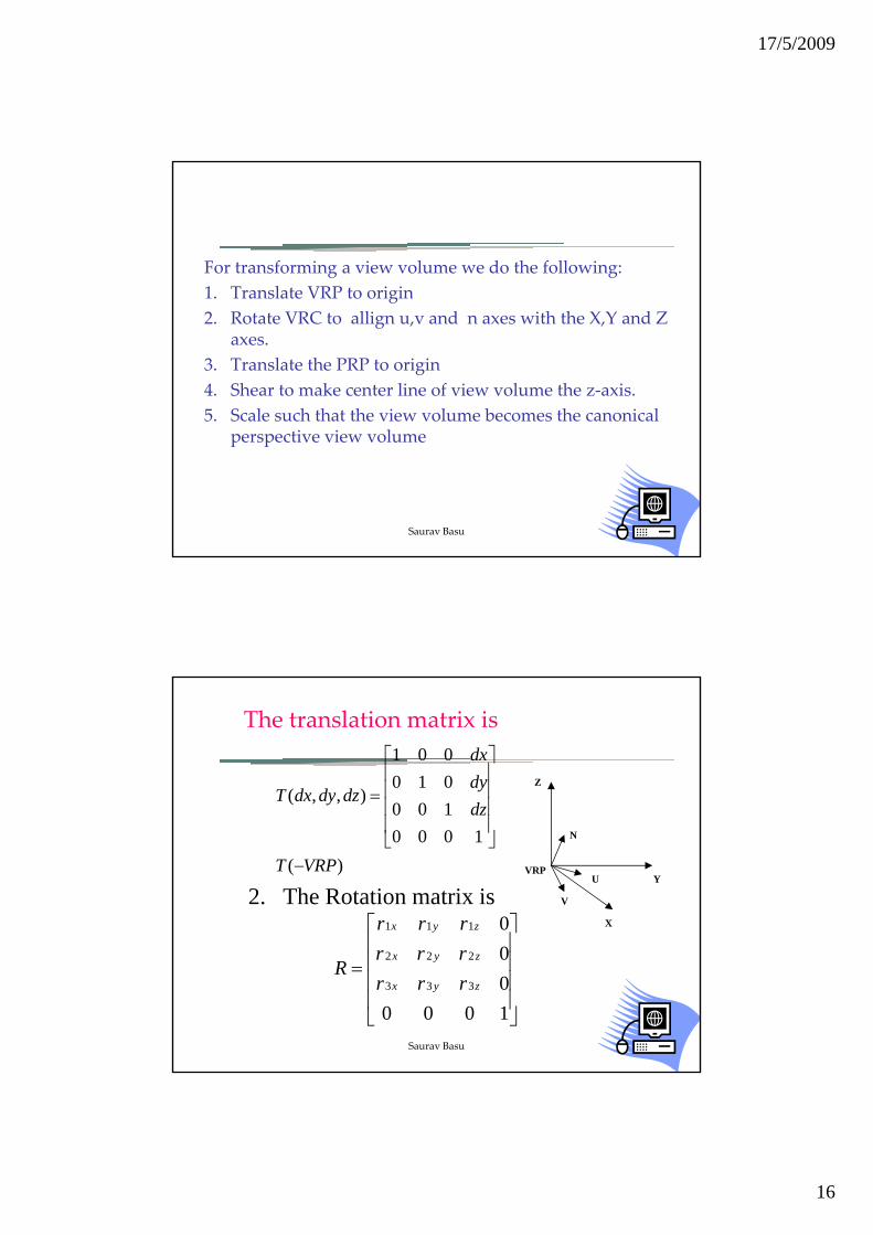
For transforming a view volume we do the following:1 Translate VRP to origin1. Translate VRP to origin2. Rotate VRC to allign u,v and n axes with the X,Y and Z
axes.3. Translate the PRP to origin4. Shear to make center line of view volume the z‐axis.5. Scale such that the view volume becomes the canonical
perspective view volume
Saurav Basu
The translation matrix is
100010001
),,(dzdydx
dzdydxT⎥⎥⎥⎤
⎢⎢⎢⎡
=Z
)(1000
100
VRPT
dz
−
⎥⎥
⎦⎢⎢
⎣
2. The Rotation matrix is
⎥⎤
⎢⎡ 0111 zyx rrr
N
V
U
X
YVRP
⎥⎥⎥⎥
⎦⎢⎢⎢⎢
⎣
=
100000
333
222
zyx
zyx
rrrrrr
R
Saurav Basu

17/5/2009
17
VPNwhere
][
][
][
222
1 1 1
3 3 3
RRrrrRRVUPRVUPrrrR
VPNVPNrrrR
z
zzyxx
zyxz
×==
××
==
==
)( 3.][ 2 2 2
PRPTRRrrrR xzzyxy
−×==
Saurav Basu
The Shear Matrix
SH shyshx
⎥⎥⎤
⎢⎢⎡
010001
Y
dopx
Let
SH shyper
=
⎥⎥⎥⎥
⎦⎢⎢⎢⎢
⎣
=
WindowofCenter :CWProjection ofDirection :DOP
PRP-CWDOP 10000100010 Y
CW
dopzdopyshy
dopzdopxshx
−=
−=
PRP -Z
Saurav Basu
17/5/2009
18
The scale transformation
⎥⎥⎤
⎢⎢⎡
00s0000s
y
x
Y
BVRPuuVRPs
PRPTSHVRPLet
S
z
zx
per
per
+=
−=
⎥⎥⎥
⎦⎢⎢⎢
⎣
=
− )')(('2
1] 0 0 0).[(.' 10000s0000s0
minmax
z
y Y
CW
Y=-Z
BVRPs
BVRPvvVRPs
zz
z
zy
+−
=
+=
−
'1
)')(('2
minmax
PRP -Z
Y=-Z
Saurav Basu
Once all the projected points have been l l t d l th di t t fit thcalculated, scale the coordinates to fit the
display screen.A wire frame display of the image is obtained by joining the projections of all points lying on the same row or column.poi yi g o e a e o o o uMap the pixel colors of the image on to the projected points to create a realistic effect.
Saurav Basu
17/5/2009
19
Limitations
Can work well only for stereo images h i t d t il t i dwhere minute details are not required.
More suited for depth estimation of landscape through images taken from top.No accurate metric calculations done.
Saurav Basu
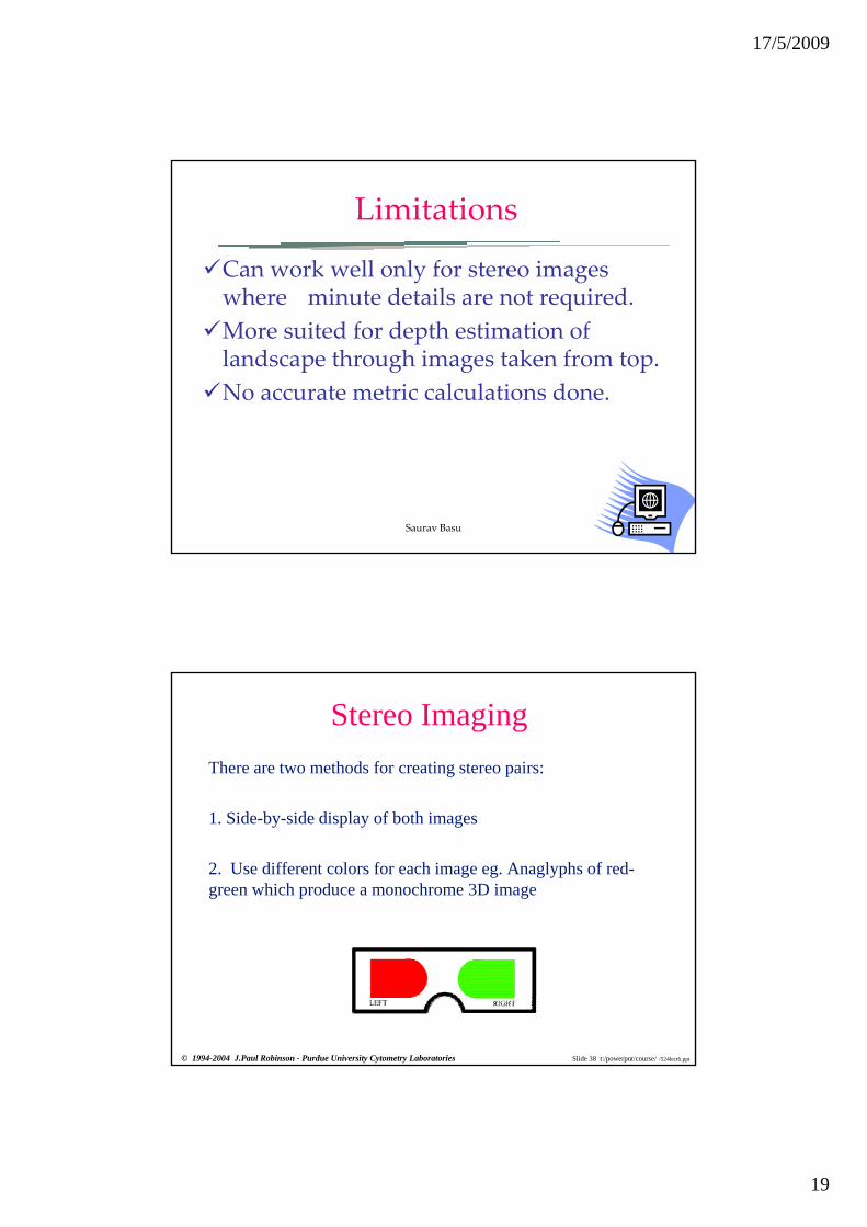
Stereo ImagingThere are two methods for creating stereo pairs:
1. Side-by-side display of both images
2. Use different colors for each image eg. Anaglyphs of red-green which produce a monochrome 3D image
Slide 38 t:/powerpnt/course/ /524lect6.ppt© 1994-2004 J.Paul Robinson - Purdue University Cytometry Laboratories

17/5/2009
20
Creating Stereo pairs
Pixel shifting -ive pixel shift for left+ive pixel shift for right
z
Slide 39 t:/powerpnt/course/ /524lect6.ppt© 1994-2004 J.Paul Robinson - Purdue University Cytometry Laboratories
xy
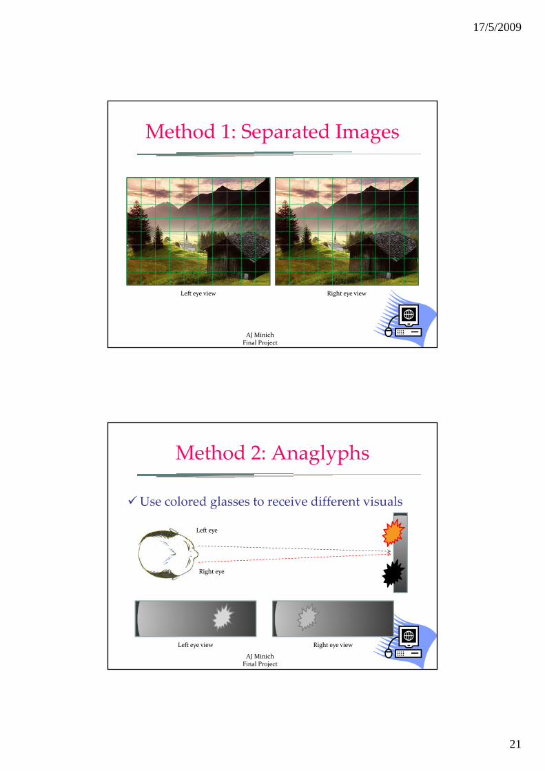
Method 1: Separated Images
Actually present two different imagesActually present two different images to the eyes
Left eye
Right eye
Left eye view Right eye view
AJ MinichFinal Project
17/5/2009
21
Method 1: Separated Images
Left eye view Right eye view
AJ MinichFinal Project
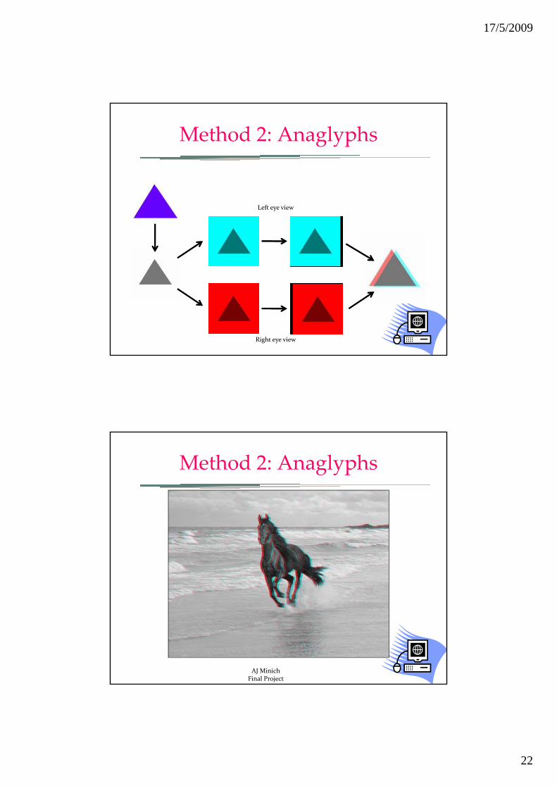
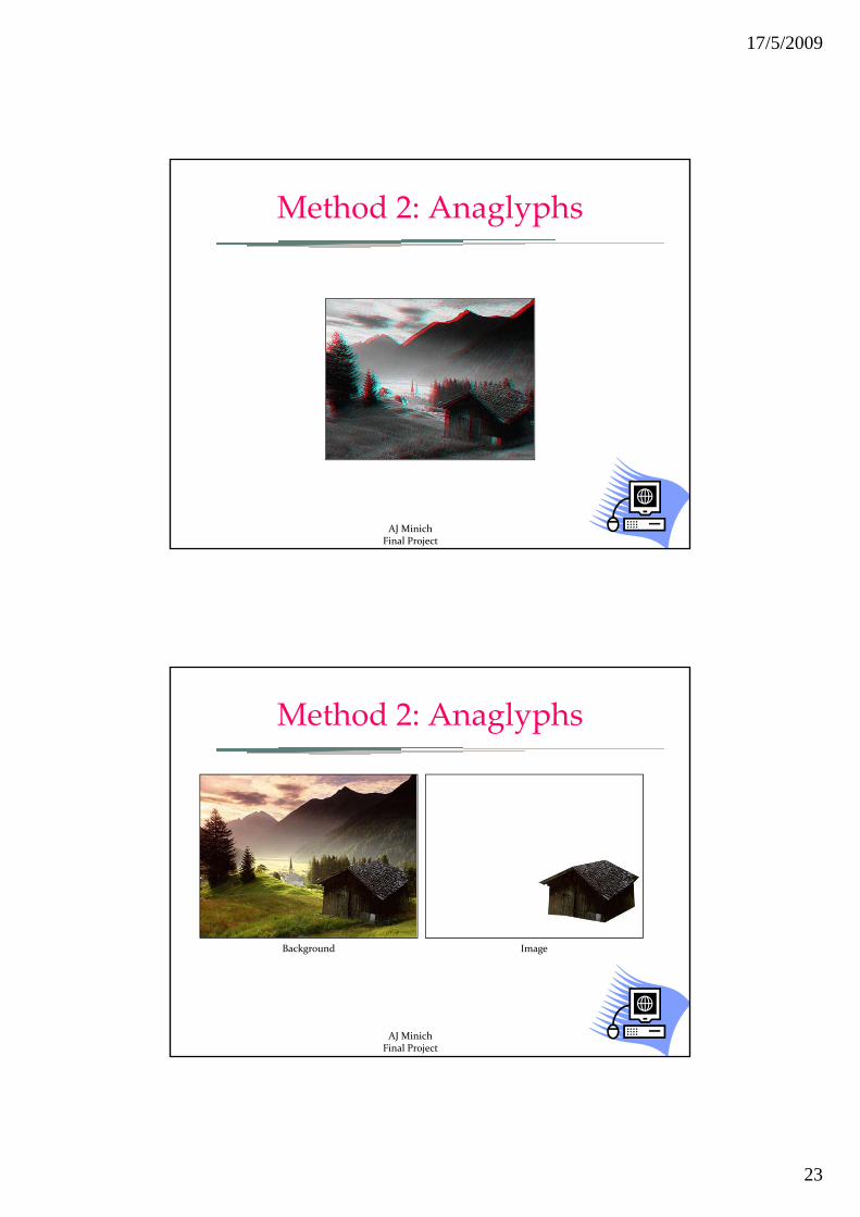
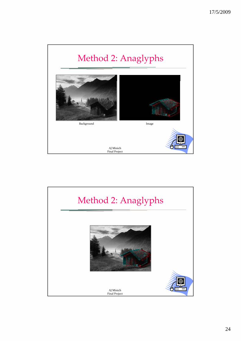
Method 2: Anaglyphs
Use colored glasses to receive different visualsUse colored glasses to receive different visuals
Left eye
Right eye
Left eye view Right eye view
AJ MinichFinal Project
17/5/2009
22
Method 2: Anaglyphs
Left eye view
Right eye view
Method 2: Anaglyphs
AJ MinichFinal Project
17/5/2009
23
Method 2: Anaglyphs
AJ MinichFinal Project
Method 2: Anaglyphs
Background Image
AJ MinichFinal Project
17/5/2009
24
Method 2: Anaglyphs
Background Image
AJ MinichFinal Project
Method 2: Anaglyphs
AJ MinichFinal Project