Embed Size (px)
Citation preview
STEP, XML, and UML:Complementary Technologies
J. Lubell - NIST
R. Peak - Georgia Tech
V. Srinivasan - IBM
S. Waterbury - NASA
ASME 2004 Design Engineering Technical Conferences (DETC) andComputers and Information in Engineering (CIE) Conference
Sept 28 - Oct 2, 2004 • Salt Lake City, Utah Paper No. DETC2004-57743
http://eislab.gatech.edu/pubs/conferences/2004-asme-detc-lubell/
Extended version in JCISE December 2004 issue:http://eislab.gatech.edu/pubs/journals/2004-jcise-peak/
Copyright © 1992-2004 by Georgia Tech Research Corporation, Atlanta, Georgia 30332-0415 USA. All Rights Reserved.Permission to reproduce and distribute for non-commercial purposes (including internal corporate usage) is hereby granted provided this notice and a proper citation are included.

2
AbstractSTEP, XML, and UML:
Complementary TechnologiesOne important aspect of product lifecycle management (PLM) is the computer-sensible representation of product information. Over the past fifteen years or so, several languages and technologies have emerged that vary in their emphasis and applicability for such usage. ISO 10303, informally known as the Standard for the Exchange of Product Model Data (STEP), contains the high-quality product information models needed for electronic business solutions based on the Extensible Markup Language (XML). However, traditional STEP-based model information is represented using languages that are unfamiliar to most application developers.
This paper discusses efforts underway to make STEP information models available in universal formats familiar to most business application developers: specifically XML and the Unified Modeling Language™ (UML®). We also present a vision and roadmap for future STEP integration with XML and UML to enable enhanced PLM interoperability.
http://eislab.gatech.edu/pubs/conferences/2004-asme-detc-lubell/
Extended version in JCISE December 2004 issue:http://eislab.gatech.edu/pubs/journals/2004-jcise-peak/
Notice: Commercial equipment and materials are identified in order to describe certain procedures. Some slides include product names for example purposes only (i.e., to help clarify the concepts presented via specific instances). In no case does such identification imply recommendation or endorsement by the authors or their organizations, nor does it imply that the materials or equipment identified are necessarily the best available for the purpose. Unified Modeling Language, UML, Object Management Group, OMG, and XMI are trademarks or registered trademarks of the Object Management Group, Inc. in the U.S. and other countries. Java is a trademark or registered trademark of Sun Microsystems, Inc. Other company, product, and service names may be trademarks or service marks of others.
3
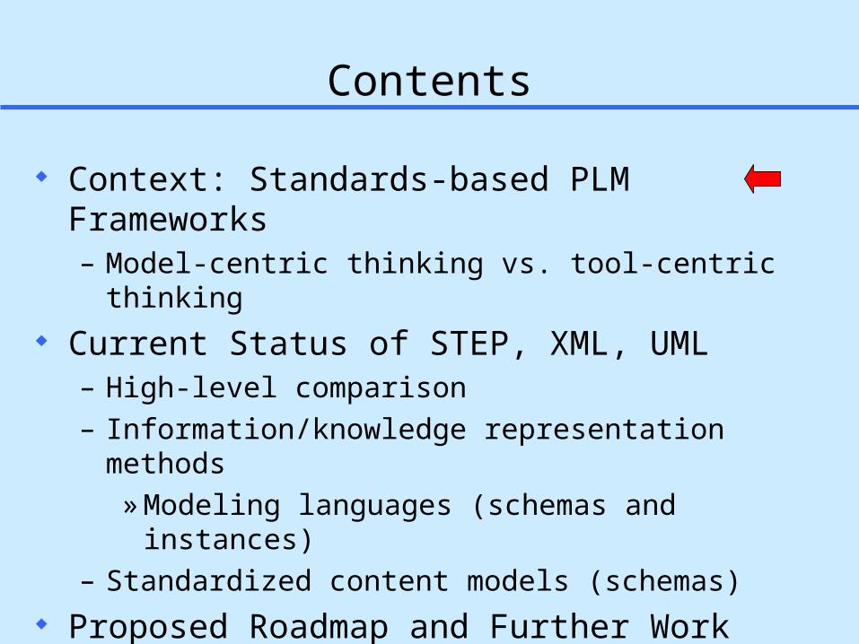
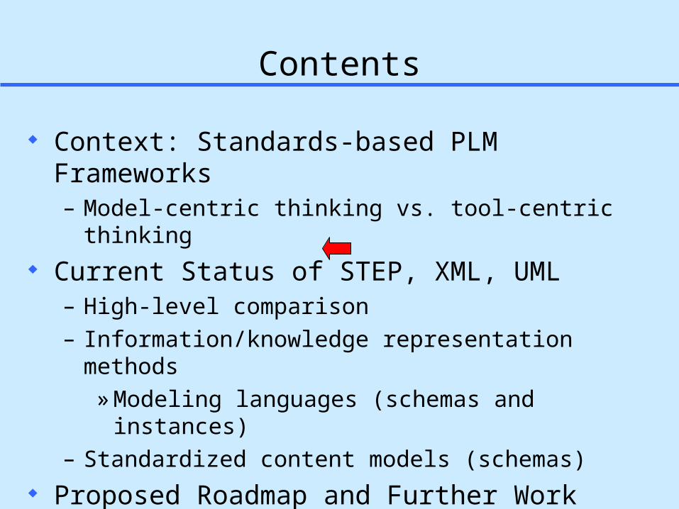
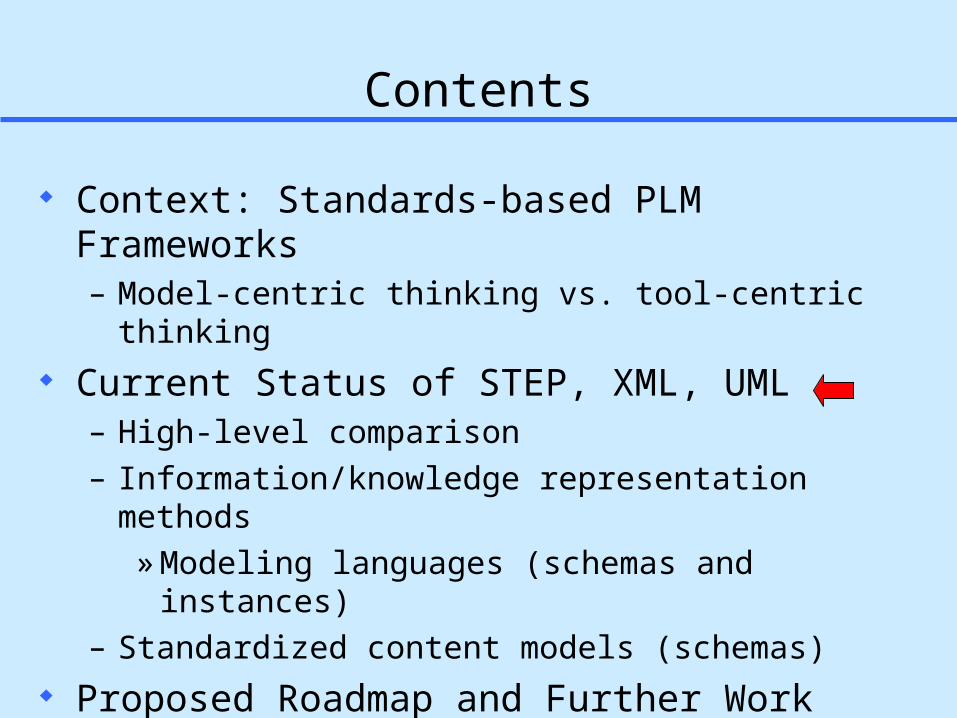
Contents
Context: Standards-based PLM Frameworks– Model-centric thinking vs. tool-centric thinking
Current Status of STEP, XML, UML– High-level comparison– Information/knowledge representation methods
» Modeling languages (schemas and instances)– Standardized content models (schemas)
Proposed Roadmap and Further Work

4
Model-Centric Standards-based Spacecraft Development
Mechanical Engineering• Standard: AP203, AP214• Software Pro-E, Cadds, SolidWorks, AutoCad, SDRC IDEAS, Unigraphics, others• Status: In Production• Aerospace Industry Wide, Automotive Industry
Electrical Engineering• Standard: AP210• Software Mentor Graphics• Status: Prototyped• Rockwell, Boeing
Cabling• Standard: AP212• Software MentorGraphics• Status: Prototyped• Daimler-Chrysler, ProSTEP
Structural Analysis• Standard: AP209• Software: MSC Patran, Thermal Desktop• Status: In Production• Lockheed Martin, Electric Boat
Thermal Radiation Analysis• Standard: STEP-TAS• Software: Thermal Desktop, TRASYS• Status: In Production• ESA/ESTEC, NASA/JPL & Langely
Software Engineering• Standard::UML - (AP233 interface In Development)• Software:Rational Rose, Argo, All-Together• Status: In Production• Industry-wide
Machining• Standard:: STEP-NC/AP224•Software:: Gibbs, •Status:: In Development / Prototyped•STEP-Tools, Boeing
Inspection• Standard: AP219• Software: Technomatics, Brown, eSharp • Status: In Development• NIST, CATIA, Boeing, Chrysler, AIAG
Systems Engineering• Standard: AP233• Software: Statemate, Doors, Matrix-X, Slate, Core, RTM• Status: In development / Prototyped• BAE SYSTEMS, EADS, NASA
PDM• Standard: STEP PDM Schema/AP232• Software: MetaPhase, Windchill, Insync• Status: In Production • Lockheed Martin, EADS, BAE SYSTEMS, Raytheon
Life-Cycle Management• Standard: PLCS• Software: SAP • Status: In Development• BAE SYSTEMS, Boeing, Eurostep
File: SLIDE_STEP-in-Spacecraft-Development-Ver4.ppt
Fluid Dynamics• Standard: CFD• Software - • Status: In Development• Boeing,
Optics• Standard: NODIF• Software - TBD • Minolta, Olympus
Propulsion• Standard: STEP-PRP• Software:- • Status: In Development• ESA, EADS
2001-12-16 - Jim U’Ren, NASA-JPL

5
Towards Standards-based PLM FrameworksModel-centric view (vs. Tool-centric view)
Eagle Traditional Tools Mentor
Graphics
ElectricalCAD Tools
AP210
Doors
Slate
Systems EngineeringTools
Pro/E
CATIA
MechanicalCAD Tools
…
AP203, AP214 AP233, SysML
Collective Product ModelBuilding Blocks: • Information models & meta-models
• International standards• Industry specs• Corporate standards• Local customizations
• Modeling technologies:• Express, XML, UML, OWL, COBs, …
XaiToolsPWA-B LKSoft, …Gap-Filling
ToolsXaiToolsPWA-B
EPM, LKSoft, STI, …
STEP-Book AP210,SDAI-Edit,
STI AP210 Viewer, ...
Instance Browser/EditorPWB Stackup Tool,…
pgef
EngineeringFramework Tool
AP210 AP2xx
Standards-based Submodels
6
Contents
Context: Standards-based PLM Frameworks– Model-centric thinking vs. tool-centric thinking
Current Status of STEP, XML, UML– High-level comparison– Information/knowledge representation methods
» Modeling languages (schemas and instances)– Standardized content models (schemas)
Proposed Roadmap and Further Work

7
Primary Information Representation Technologies for Standards-based PLM Frameworks
(STEP Part 11)
Information Modeling Implementation Methods Standardized Content
8
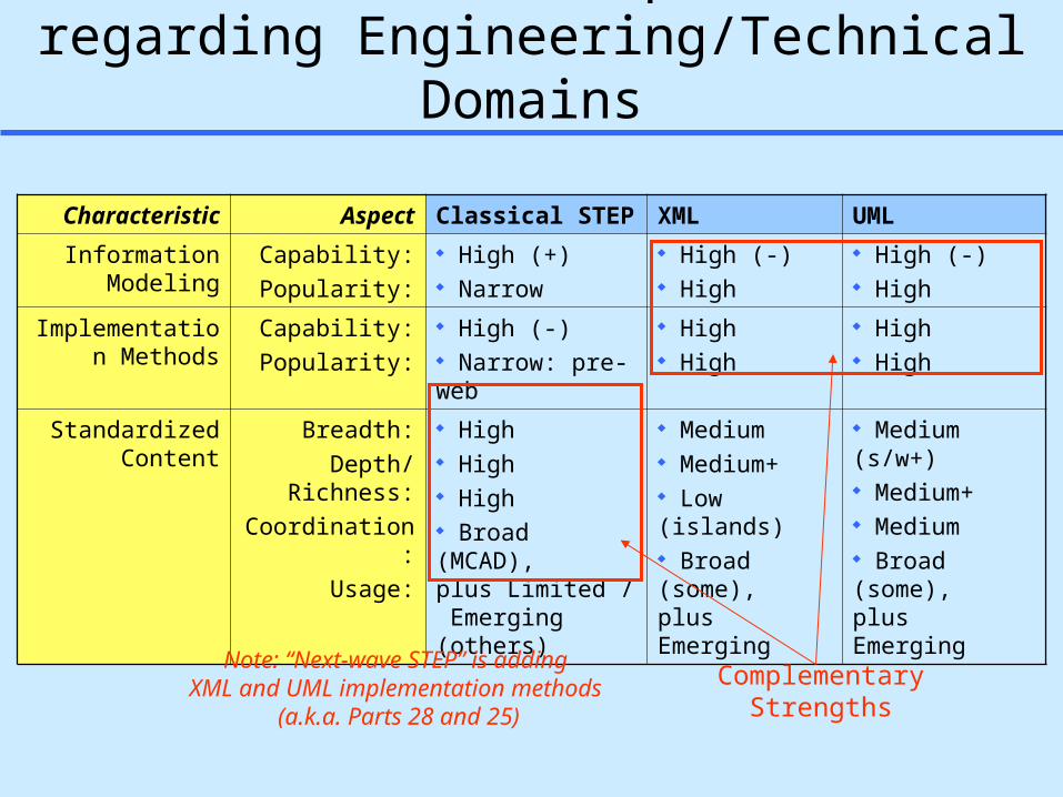
STEP, XML, UML Capabilitiesregarding Engineering/Technical Domains
Characteristic Aspect Classical STEP XML UML
Information Modeling
Capability:
Popularity:
High (+) Narrow
High (-) High
High (-) High
Implementation Methods
Capability:
Popularity:
High (-) Narrow: pre-web
High High
High High
Standardized Content
Breadth:
Depth/Richness:
Coordination:
Usage:
High High High Broad (MCAD),plus Limited / Emerging (others)
Medium Medium+ Low (islands) Broad (some),plus Emerging
Medium (s/w+) Medium+ Medium Broad (some),plus Emerging
ComplementaryStrengths
Note: “Next-wave STEP” is adding XML and UML implementation methods
(a.k.a. Parts 28 and 25)
9
Contents
Context: Standards-based PLM Frameworks– Model-centric thinking vs. tool-centric thinking
Current Status of STEP, XML, UML– High-level comparison– Information/knowledge representation methods
» Modeling languages (schemas and instances)– Standardized content models (schemas)
Proposed Roadmap and Further Work

10
Information Model: simple_drawingsExpress lexical and graphical schema formats
SCHEMA simple_drawings;
ENTITY drawing; name : STRING; elements : SET [1:?] OF shape;END_ENTITY;
ENTITY shape; label : STRING;END_ENTITY;
ENTITY point SUBTYPE OF (shape); x : REAL; y : REAL;END_ENTITY;
ENTITY line SUBTYPE OF (shape); end1 : point; end2 : point;END_ENTITY;
END_SCHEMA;
Express Express-G
Note: Another way for handling part-of relationships rather than SET as above is to use INVERSE as introduced earlier.
end1
end2
1
x
y
label
name elements
S[1:?]
shape
linepoint
drawingSTRING
REAL

11
Information Model: simple_drawingsXML format
<xs:schema xmlns:xs="http://www.w3.org/2001/XMLSchema">
<xs:attributeGroup name="OID"> <xs:attribute name="id" type="xs:ID" use="optional"/> </xs:attributeGroup>
<xs:element name="p28data"> <xs:complexType> <xs:choice minOccurs="1" maxOccurs="unbounded"> <xs:element name="drawing" type="Drawing"/> <xs:element name="point" type="Point"/> <xs:element name="line" type="Line"/> </xs:choice> </xs:complexType> </xs:element>
<xs:complexType name="Drawing"> <xs:sequence> <xs:element name="name" type="xs:string"/> <xs:element name="elements"> <xs:complexType> <xs:choice maxOccurs="unbounded"> <xs:element name="line" type="Line-ref"/> <xs:element name="point" type="Point-ref"/> </xs:choice> </xs:complexType> </xs:element> </xs:sequence> <xs:attributeGroup ref="OID"/> </xs:complexType>
Express XML schema mapping done via STEP Part 28
<xs:complexType name="Shape"> <xs:sequence> <xs:element name="label" type="xs:string"/> </xs:sequence> <xs:attributeGroup ref="OID"/> </xs:complexType>
<xs:complexType name="Point"> <xs:complexContent> <xs:extension base="Shape"> <xs:sequence> <xs:element name="x" type="xs:decimal"/> <xs:element name="y" type="xs:decimal"/> </xs:sequence> </xs:extension> </xs:complexContent> </xs:complexType> <xs:complexType name="Point-ref"> <xs:attribute name="ref" type="xs:IDREF"/> </xs:complexType>
<xs:complexType name="Line"> <xs:complexContent> <xs:extension base="Shape"> <xs:sequence> <xs:element name="end1" type="Point-ref"/> <xs:element name="end2" type="Point-ref"/> </xs:sequence> </xs:extension> </xs:complexContent> </xs:complexType> <xs:complexType name="Line-ref"> <xs:attribute name="ref" type="xs:IDREF"/> </xs:complexType>
</xs:schema>

12
Information Model: simple_drawingsUML class diagram
Express UML mapping done via STEP Part 25
13
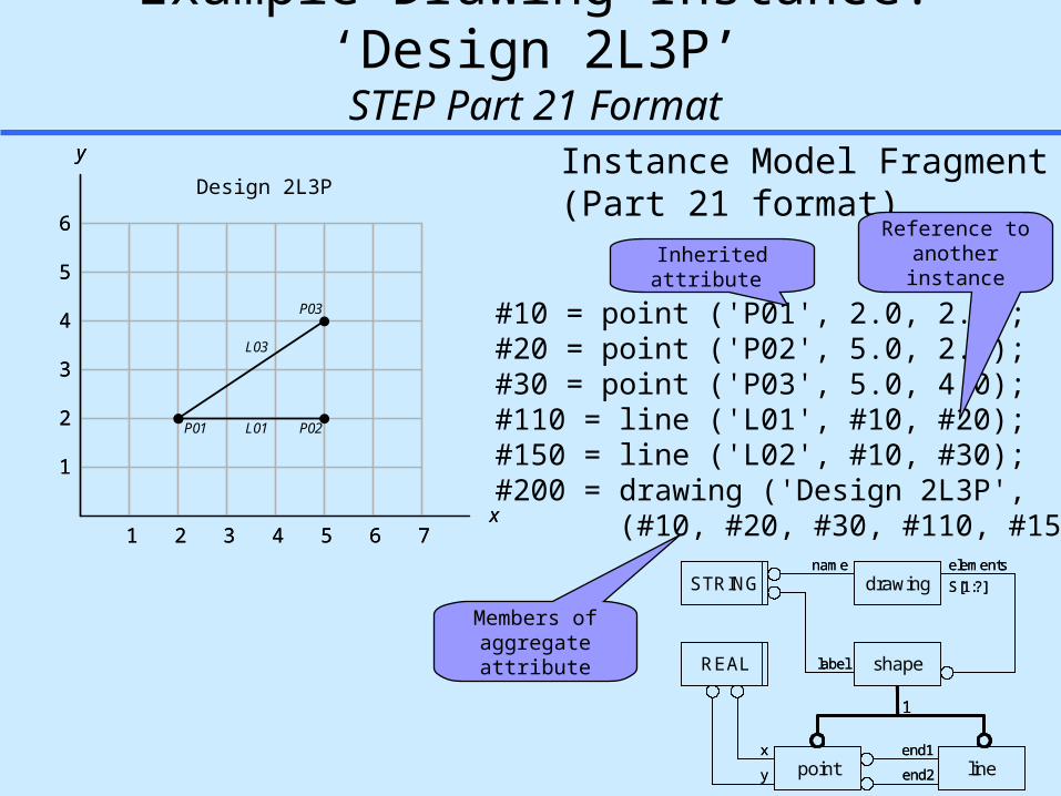
Example Drawing Instance: ‘Design 2L3P’STEP Part 21 Format
21 3 4 5 6 7
2
1
3
4
5
6
x
y
21 3 4 5 6 7
2
1
3
4
5
6
x
y
P01 L01 P02
L03
P03
Instance Model Fragment(Part 21 format)
#10 = point ('P01', 2.0, 2.0);#20 = point ('P02', 5.0, 2.0);#30 = point ('P03', 5.0, 4.0);#110 = line ('L01', #10, #20);#150 = line ('L02', #10, #30);#200 = drawing ('Design 2L3P', (#10, #20, #30, #110, #150));
Inherited attribute
Members of aggregate attribute
Design 2L3P
end1
end2
1
x
y
label
name elements
S[1:?]
shape
linepoint
drawingSTRING
REAL
end1
end2
1
x
y
label
name elements
S[1:?]
shape
linepoint
drawingSTRINGSTRING
REALREAL
Reference to another instance

14
Example Drawing Instance: ‘Design 2L3P’XML Format (Part 28 mapping)
21 3 4 5 6 7
2
1
3
4
5
6
x
y
21 3 4 5 6 7
2
1
3
4
5
6
x
y
P01 L01 P02
L03
P03
Instance Model Fragment (Part 28 format)<p28data> <point id="_10"> <label>P1</label> <x>2.0</x> <y>2.0</y> </point> <point id="_20"> <label>P2</label> <x>5.0</x> <y>2.0</y> </point> <point id="_30"> <label>P3</label> <x>5.0</x> <y>4.0</y> </point> <line id="_110"> <label>L1</label> <end1 ref="_10"/> <end2 ref="_20"/> </line>
Design 2L3P<line id="_150"> <label>L2</label> <end1 ref="_10"/> <end2 ref="_30"/> </line> <drawing id="_200"> <name>Design 2L3P</name> <elements> <point ref="_10"/> <point ref="_20"/> <point ref="_30"/> <line ref="_110"/> <line ref="_150"/> </elements> </drawing></p28data>

15
Contents Context: Standards-based PLM Frameworks
– Model-centric thinking vs. tool-centric thinking Current Status of STEP, XML, UML
– High-level comparison– Information/knowledge representation methods
» Modeling languages (schemas and instances)– Standardized content models (schemas)
Proposed Roadmap and Further Work
16
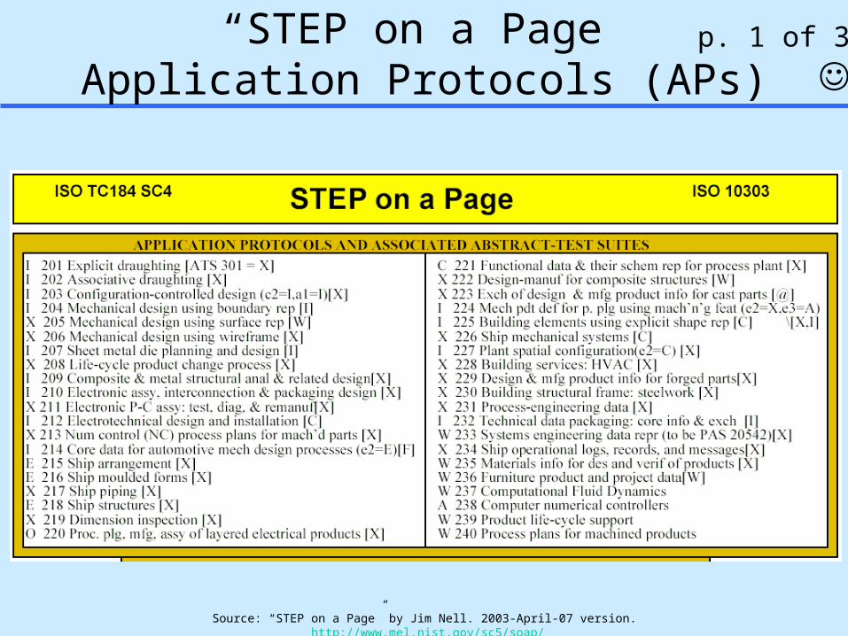
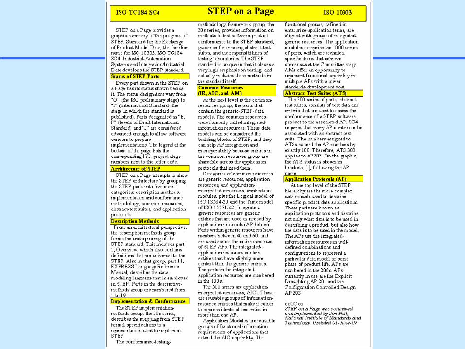
“STEP on a Page”Application Protocols (APs)
Source: “STEP on a Page” by Jim Nell. 2003-April-07 version. http://www.mel.nist.gov/sc5/soap/
p. 1 of 3

17
STEP on a Page - IRs, etc.
18
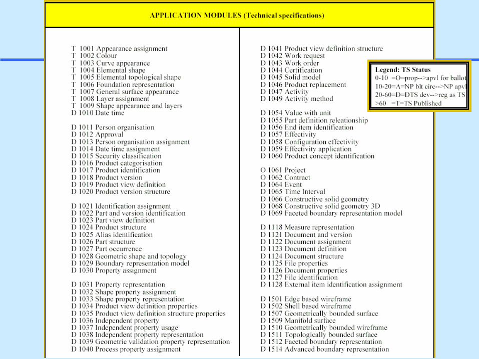
STEP on a Page - App. Modules (AMs)

19
Contents Context: Standards-based PLM Frameworks
– Model-centric thinking vs. tool-centric thinking Current Status of STEP, XML, UML
– High-level comparison– Information/knowledge representation methods– Standardized content models (schemas)
» Example next-wave of STEP: Rich product models and tools (AP210, AP212, AP214)
Proposed Roadmap and Further Work
20
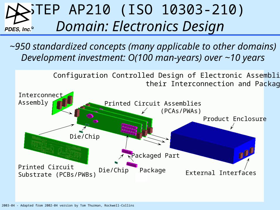
Product Enclosure
External Interfaces
Printed Circuit Assemblies(PCAs/PWAs)
Die/Chip Package
Packaged Part
InterconnectAssembly
Printed Circuit Substrate (PCBs/PWBs)
Die/Chip
STEP AP210 (ISO 10303-210) Domain: Electronics DesignR
~950 standardized concepts (many applicable to other domains)Development investment: O(100 man-years) over ~10 years
2003-04 - Adapted from 2002-04 version by Tom Thurman, Rockwell-Collins
Configuration Controlled Design of Electronic Assemblies,their Interconnection and Packaging

21
STEP AP210 Scope
Scope is “As-Required” & “As-Designed” Product Information – Design “In Process” & “Release”– Design views (white boxes) & usage views (black boxes)– Design at individual or multiple levels:
microsystems, packages, PCAs, units, … Sharing Partners:
– Engineering Domains– Design / Analysis– Manufacturing / Analysis
Sharing Across Several Levels of Supply Base
R

STEP AP210 Models
Assembly Models
• User View• Design View• Component Placement• Material product• Complex Assemblies with Multiple Interconnect
Component / Part Models
• Analysis Support • Package• Material Product• Properties• “White Box”/ “Black Box”• Pin Mapping
Requirements Models• Design• Constraints• Interface• Allocation
Functional Models
• Functional Unit• Interface Declaration• Network Listing• Simulation Models• Signals
Interconnect Models
• User View• Design View• Bare Board Design• Layout templates• Layers
planarnon-planar
conductive non-conductive
Configuration Mgmt• Identification• Authority • Effectivity • Control• Net Change
GD & T Model
• Datum Reference Frame• Tolerances
R

23
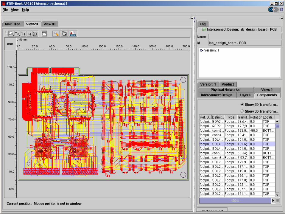
Rich Features in AP210: PWB tracesAP210 STEP-Book Viewer - www.lksoft.com

24
Rich Features in AP210: Via/Plated Through Hole
Z-dimension details …

25
Rich Features in AP210: PCB Assembly: 3D & 2D STEP-Book AP210 Browser - www.lksoft.com
PDES Inc. EM Pilot Test Case:
Cable Order Wire (COW) Board

26
Rich Features in AP210: Electrical Component
The 3D shape is generated from these “smart features” which have electrical functional knowledge. Thus, the AP210-based model is much richer than a typical 3D MCAD package model.
210 can also support the detailed design of a package itself (its insides, including electrical functions and physical behaviors).

27
28
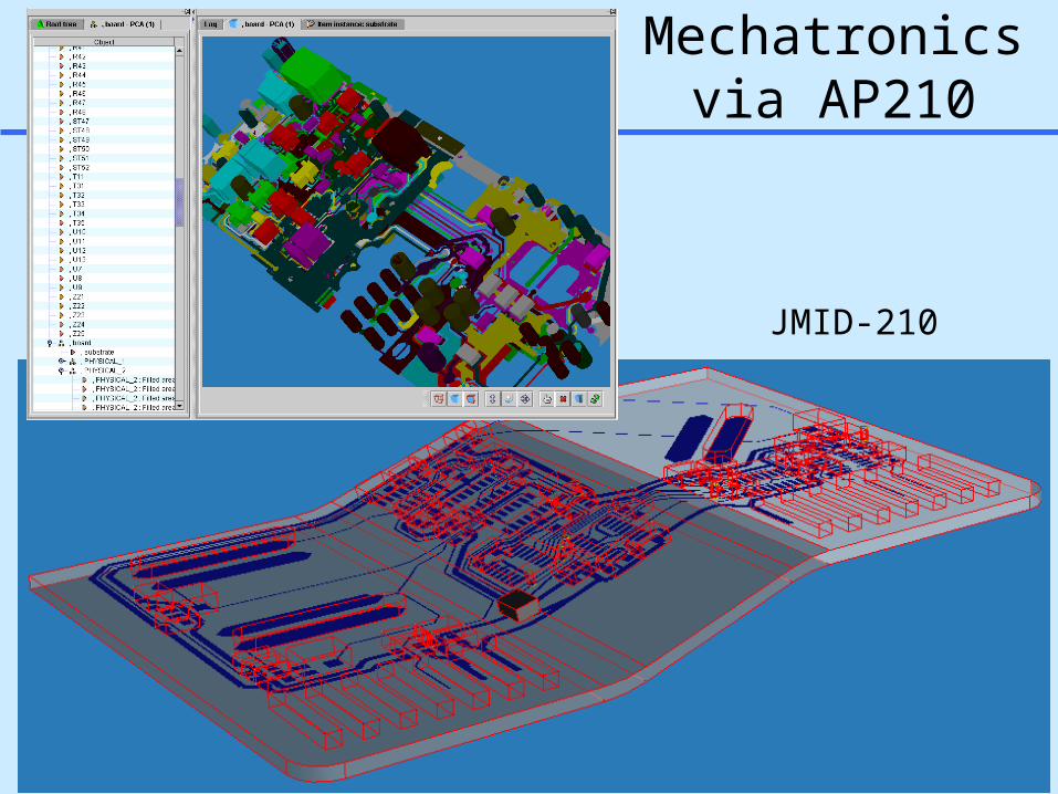
3D Mechatronicsvia AP210
JMID-210

29
Using Rich Product Models to Drive Analysis Complex Idealizations via AP210 for Circuit Board Warpage Analysis
Grid (Sieve) Size
Single Layer View
…
Top view of “effective” grid elements in top layer of the PCB
…
Side view of the PCB with “effective” grid elements across
the stratums
thickness
wid
th
length
Given:
• Thermal loading profile
• Boundary Conditions (mostly displacement)
• Idealize PWB stackup as a layered shell
Analysis Model (Analytical Level)AP210 Design Model Idealizations
Effective Material Property
Computation
Analysis template attributes
• Thermal loading profile
• Boundary Conditions (mostly displacement)
• Idealize PWB stackup as a layered shell

30
-100
-50
0
50
100
150
200
Te
mp
era
ture
(C
)
0
5
10
15
20
25
Model Exp't
Sca
le (
mil
s)
0 C
Example Warpage Results - ECAD to FEA via AP210
Experimental Results

31
AP 212: Electrotechnical Design and Installation
Electrotechnical Equipment in Industry
Electrotechnical Plant• Plant, e.g., Automobile• Unit, e.g., Engine Control System• Subunit, e.g., Ignition System
Electrotechnical Systems• Buildings • Plants• Transportation Systems
Equipment Coverage• Power-transmission• Power-distribution• Power-generation• Electric Machinery• Electric Light and Heat• Control Systems
Data Supporting• Terminals and Interfaces• Functional Decomposition of Product• 3D Cabling and Harnesses• Cable Tracks and Mounting Instructions
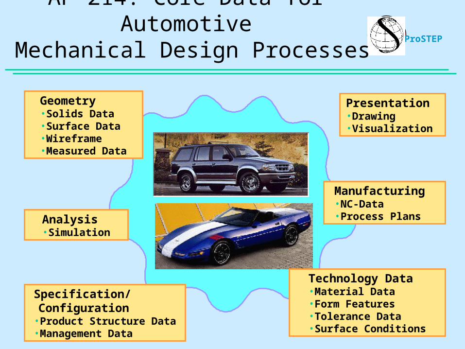
Geometry• Solids Data• Surface Data• Wireframe• Measured Data
Analysis•Simulation
Technology Data•Material Data•Form Features•Tolerance Data•Surface Conditions
Manufacturing•NC-Data•Process Plans
Specification/Configuration•Product Structure Data•Management Data
Presentation•Drawing•Visualization
ProSTEPAP 214: Core Data for Automotive
Mechanical Design Processes

33
IDA-STEP Overview
IDA-STEP Viewer (v1.2 - May, 2004 - free download)
– Supports AP203, AP212, AP214– Downloadable from www.ida-step.net
IDA-STEP Center version – Adds editing and transformation/export capabilities– Supports repository interfaces
Example end-user tool for viewing and editing rich product models
in an open standards-based PLM environment

34
Linking Intelligent 3D with Product Structure
35
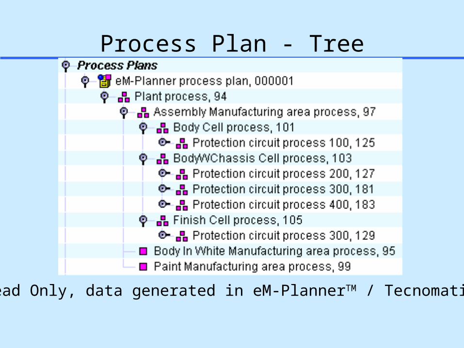
Process Plan - Tree
Read Only, data generated in eM-PlannerTM / Tecnomatix

36
Linking Intelligent 2D (e.g. Factory Layout) with Product Structure

37
Example Features and Usage of Standards-based Tools for Rich Product Models (IDA-STEP v1.2)
AP203, AP212, AP214 and PDM-Schema support Viewing 2D & 3D geometry and intelligent schematics Creation and editing of rich PLM information Single user versions (PC, Workstation) Multi-user environments:
STEP database using MySQL and Oracle
Target Usage Standards-based PLM for SMEs Prime-SME collaboration via rich product models
The Adobe Acrobat / pdf equivalent for rich product models

38
Contents
Context: Standards-based PLM Frameworks– Model-centric thinking vs. tool-centric thinking
Current Status of STEP, XML, UML Proposed Roadmap and Further Work
– Complementary technologies working together

39
Complementary Usage of STEP, UML, and XML for Systems Engineering: Envisioned AP233-SysML Relationship
AP-233 NeutralInfo Exchange
Format
AP-233 NeutralInfo Exchange
Format
ElectricalCAE
ElectricalCAE
MechanicalCAD
MechanicalCAD
SW DevEnvironment
SW DevEnvironment
AlgorithmDesign
AlgorithmDesign
TestingTools
TestingTools
PlanningTools
PlanningTools
XMI (XML Metamodel-
Interchange for UML)
SysMLToolsSysMLTools Systems
EngineeringSystems
Engineering
AP-233 NeutralInfo Exchange
Format
AP-233 NeutralInfo Exchange
Format
ElectricalCAE
ElectricalCAE
MechanicalCAD
MechanicalCAD
SW DevEnvironment
SW DevEnvironment
AlgorithmDesign
AlgorithmDesign
TestingTools
TestingTools
PlanningTools
PlanningTools
XMI (XML Metamodel-
Interchange for UML)
SysMLToolsSysMLTools Systems
EngineeringSystems
Engineering
Source: www.SysML.org 2003-12

40
Summary
STEP, XML, UML are complementary technologies– STEP provides standardized rich content models
» Next-wave capabilities are also emerging– XML and UML provide ubiquitous implementation methods
Further needed work:– More detailed comparison methods and metrics for:
» Information modeling capabilities» Content models
– Investigations & comparisons with other techniques:» OWL (ontologies/semantic web)» Schematron (XML-based schema rules/constraints)

Backup Slides

42
Domain
Abs
trac
tion
Leve
l
Req
uire
men
ts
Sof
twa
re
Ele
ctro
nics
Str
uctu
res
Systems Engineering
Models of varying abstractions and domains
Legend
Model interfaces:Fine-grained associativity relations among domain-specific models and system-level models
Dev
elop
men
t Pro
cess
…
Rich models: Information objects Parametric relations
…
…
… …
…
After Bajaj, Peak, & Waterbury2003-09
Next-Generation PLM Framework with Fine-Grained Interoperability
Customer/Acquisitions…
…
…
Hum
an
Inte
rfac
es
…
2004-09

43
ECAD Bound Design
MGC BoardStation ECAD-
Oriented PDM
MGC DMS
MCAD Bound Design
PTC Pro/Engineer 2001 MCAD-
Oriented PDM
PTC ProjectLink
Level 1: Domain-Level PDM• Interactive WIP design collaboration: main tools• Tight integration w/ major domain-specific CAD tools
… ____________
Native Files
DBMS
____________
Native Files
DBMS
Oracle
Oracle Basic Objects
& Relations(Macro-level associativity)
Level 2: Workgroup-Level PDM• Interactive WIP design collaboration• Focus on inter-tool information interoperability
Limitations:• Content coverage and semantics gaps• Fine-grained associativity gaps
• Even within a native file • Esp. between attributes in monolithic native files
• Dynamic interactivity lacking vs. batch releases
Custom software and person-ware (manual) glue
Enterprise PDM
EDS Metaphase
Level 3: Enterprise-Level PDM• Major releases (to manufacturer, to supplier, …)• Long term archiving
Plus other enterprise resources: Document Mgt. Systems
(e.g., DocuShare), …____________
Native Files
DBMS
Oracle
Current Typical Levels of PDM System Deployment and Limitations

44
Knowledge Representation Elements
KnowledgeRepresentation
DefinitionLanguages
Meta-Model
GraphicalRepresentations
Protocol
Operations/Methods
Structure/Content
45
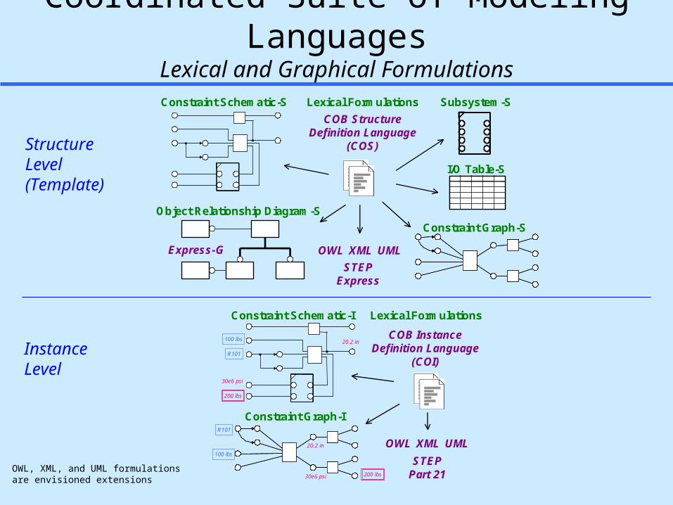
Coordinated Suite of Modeling LanguagesLexical and Graphical Formulations
StructureLevel(Template)
InstanceLevel
Subsystem-S
Object Relationship Diagram-S
COB StructureDefinition Language
(COS)
I/O Table-S
Constraint Graph-S
Constraint Schematic-S
STEPExpress
Express-G
Lexical Formulations
OWL UMLXML
COB InstanceDefinition Language
(COI)
Constraint Graph-I
Constraint Schematic-I
STEPPart 21
200 lbs
30e6 psi
100 lbs 20.2 in
R101
R101
100 lbs
30e6 psi 200 lbs
20.2 in OWL UML
Lexical Formulations
XML
OWL, XML, and UML formulationsare envisioned extensions
46
STEP on a Page - Explanation
47
48
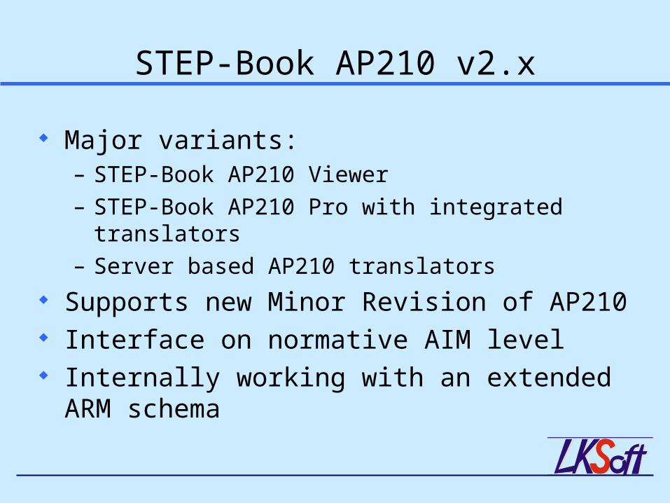
STEP-Book AP210 v2.x
Major variants:– STEP-Book AP210 Viewer– STEP-Book AP210 Pro with integrated translators– Server based AP210 translators
Supports new Minor Revision of AP210 Interface on normative AIM level Internally working with an extended ARM schema

49
STEP-Book AP210 Pro v2.1
Cadence / OrCAD translator under development
Ongoing round robbin tests
ECAD Interfaces Import ExportMentor / Boardstation PCB & PCA PCB & PCA
Zuken / Visula-CADIF PCB & PCA PCB & PCA
CadSoft / EAGLE PCB & PCA PCB & PCA
Mentor / PADS PCB & PCA
GERBER PCB only
Valor / ODB++ PCB only
AP203 / 214 PCA (& PCB)
AP210 All All

50
Schematron Diagnostics for“Design 2L3P” XML Instance Example