Embed Size (px)
Citation preview
STEP CARE FOR BLIND
H. Bharathi1, S.V.S. Prasad2,B.Adinarayana Reddy3,
1,2Department of Electronics and CommunicationEngineering, MLR Institute of Technology,3Institute of Technologyand Management,
Hyderabad, 500043, [email protected]
July 23, 2018
Abstract
Blind people need some aid to feel safe while moving.Step care for blind comes as a proposed solution to improvethe mobility of both blind and visually impaired people.This step care for blind device is however valuable in outsidecondition it can likewise be useful as an unattractive indi-vidual guide. Extensive hindrances, in this we have utilizedcounterfeit consciousness which can detect the earth arounda visually impaired individual. To accomplish this we haveutilized a few sensors like Ultra sonic sensor, IR sensor,Moisture sensor to recognize/sensor the obstacles, vehicles,different people on foot, water introduce on ground or streetand gaps on street. This task will give alarm for the visu-ally impaired individual by vibrations and voice charges forroute on outside and also inside. This will explore/controlthe visually impaired individual in the protected and rightapproach to achieve their goal.
Key Words:Arduino mega, IR sensor, Ultrasonic sen-sor, Moisture sensor, Motor driver, Apr33a3 voice module,Speakers.
1
International Journal of Pure and Applied MathematicsVolume 120 No. 6 2018, 9621-9634ISSN: 1314-3395 (on-line version)url: http://www.acadpubl.eu/hub/Special Issue http://www.acadpubl.eu/hub/
9621
1 Introduction
Throughout the years physically tested individuals are abused, tras-hed and are finishes up as barrenly ones. As indicated by factualprofile 2016 on cripple people India has the biggest visually im-paired populace. A portion of these are conceived crippled and restare the casualties of awful removals.Accessibility to the surround-ings is important for all Individuals, but access does not includeonly physical mobility, such as making a voyage between two Pre-defined points by a selected transportation type, but also being ableto recognize decision points in the neighbouring environment, suchasobstacles and signs. Accessibility therefore involves the ability tointerpret, recognize and understand the arrangement off featuresin the environment as well as being able to find the way indepen-dently [1].In past years, several electronic aid devices, called elec-tronic travel aids (ETA), were introduced as a substitute for thewhite cane. Different implementation approaches combine varioustypes of sensors, cameras or feedback channels. They all aim toimprove the mobility of visually impaired individuals. One suchexample can be found in [2] where a wear able navigation deviceis presented. A 2D vibrator array attached to the users chest islinked to a portable computer (Tyflos) and provides tactile feed-back based on the images captured by two miniature cameras. An-other example of device with haptic feedback is described in [3].The authors started with the supposition that the user is aware ofthe cane inclination and hence of the obstacle place. The two ultra-sonic sensors are placed on a short cane and the user can detect theobstacle position (left, center or right) by moving the cane left toright and vice versa while walking in the environment. One of themost used ways to determine the distance and direction of an objectis by means of ultrasound reflections commonly called ultrasonicecholocation. The same principle was exploited in[4]. The authorsdeveloped a portable device that features are chargeable polymerlithium battery, a potentiometer to adjust the range and sensitiv-ity, an ultrasonic sensor and a MCU. Alongside mobility,visuallyimpaired individuals deserve an enhanced access to some sort of in-formation that for other individuals is straightforwardly reachable(such as books or newspapers). The standard writing system usedby blind and visually impaired people is the Braille alphabet. A
2
International Journal of Pure and Applied Mathematics Special Issue
9622
solution to convert digitally stored text into Braille using solenoidsispresented in [5] where a secure digital (SD) card is used to storetext files. The characters are converted one by one on a displayunit in Braille format using six solenoids to represent the letter ina format effortlessly interpretable by the user. Another key aspectof accessibility for visually impaired individuals is magnification. Asolution for this is provided in[6] where Google Glasses are used tohelp low-vision Smartphone users by magnifying screenshots of thedisplay that are sent in real time via Bluetooth. Up to 7 framesper second (FPS) can be transferred by the system at 8x magni-fication, which is adequate for tasks where the content does notvary at fast rates. Be that as it may, innovation for the crippled hasbeen made numerous advances over the current year. The thingsthey have been doing to help impaired individuals to have the ca-pacity to remain with the propel innovation that has been goingahead on the planet. This cause the crippled to do fundamentalthings that we have thought to be an effortlessly open event onesuch assistive innovation for outwardly impaired is ”STEP CAREFOR BLIND” which can help dazzle individuals in versatility andcarrying on with an autonomous life. Truth be told, physical devel-opments are one of the real issues for daze individuals. Strolling forthese individuals may posture extremely extraordinary trouble. Inlight u, b l of this low sight vision a visually impaired may conveyindividual watchman to help them or to explore or track them toexplore obscure environment or situations.
1.1 Effect and Social Relevance
Individuals who are outwardly debilitated face number of issuesin India, where living with incapacities can be made exceptionallydifficult. Walkers are frequently constrained off of walkways thatare jumbled with merchants, creatures and different impediments.Furthermore, due to the trouble of moving freely, recovering ad-ministrations is likewise troublesome. For case, the Daze People’sAffiliation of India approximates that elite around 5 percent of thenation’s outwardly impeded kids are enrolled for instruction.
3
International Journal of Pure and Applied Mathematics Special Issue
9623
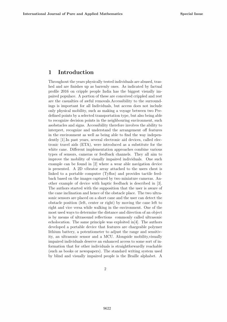
1.2 Block Diagram
Figure 1. Block Diagram of Step Care for Blind
2 HardWare Discription
2.1 Arduino Mega
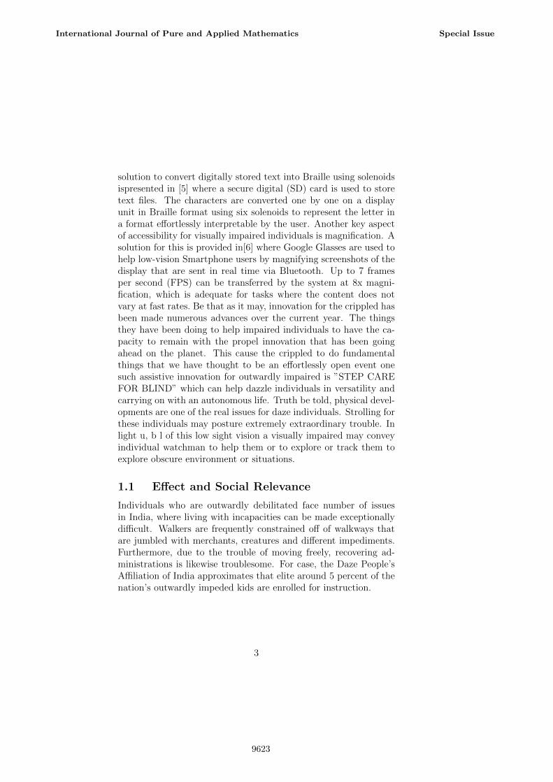
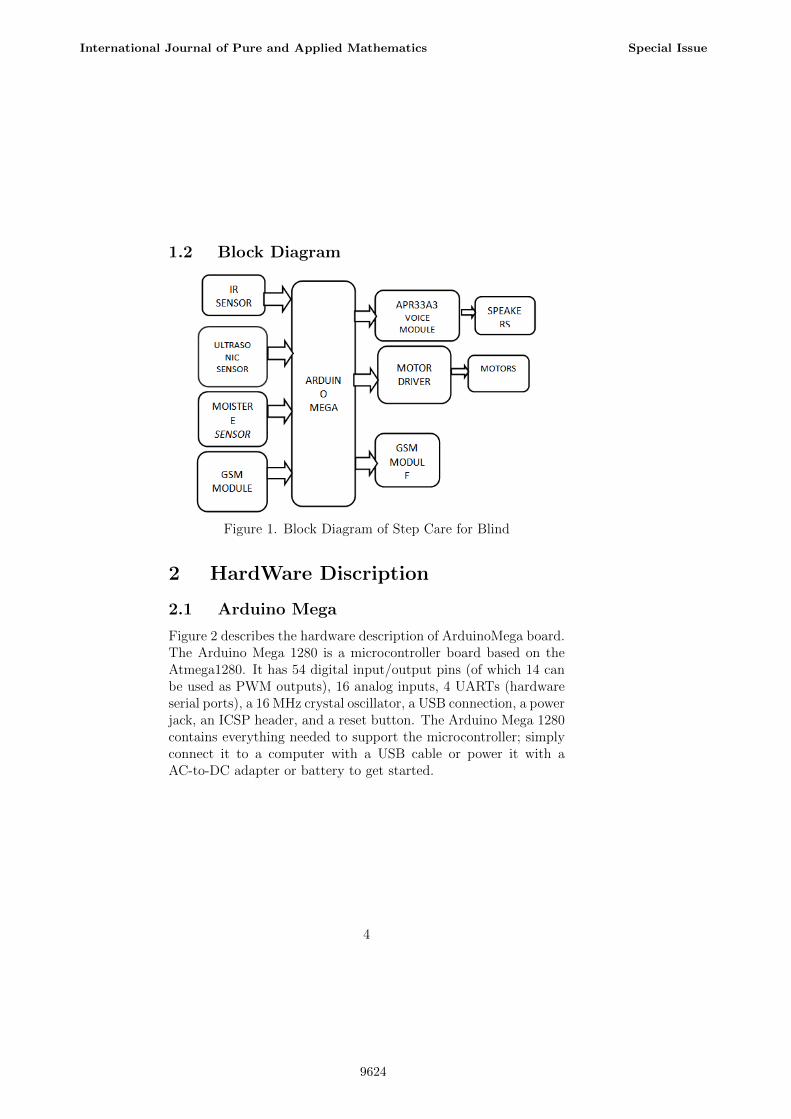
Figure 2 describes the hardware description of ArduinoMega board.The Arduino Mega 1280 is a microcontroller board based on theAtmega1280. It has 54 digital input/output pins (of which 14 canbe used as PWM outputs), 16 analog inputs, 4 UARTs (hardwareserial ports), a 16 MHz crystal oscillator, a USB connection, a powerjack, an ICSP header, and a reset button. The Arduino Mega 1280contains everything needed to support the microcontroller; simplyconnect it to a computer with a USB cable or power it with aAC-to-DC adapter or battery to get started.
4
International Journal of Pure and Applied Mathematics Special Issue
9624
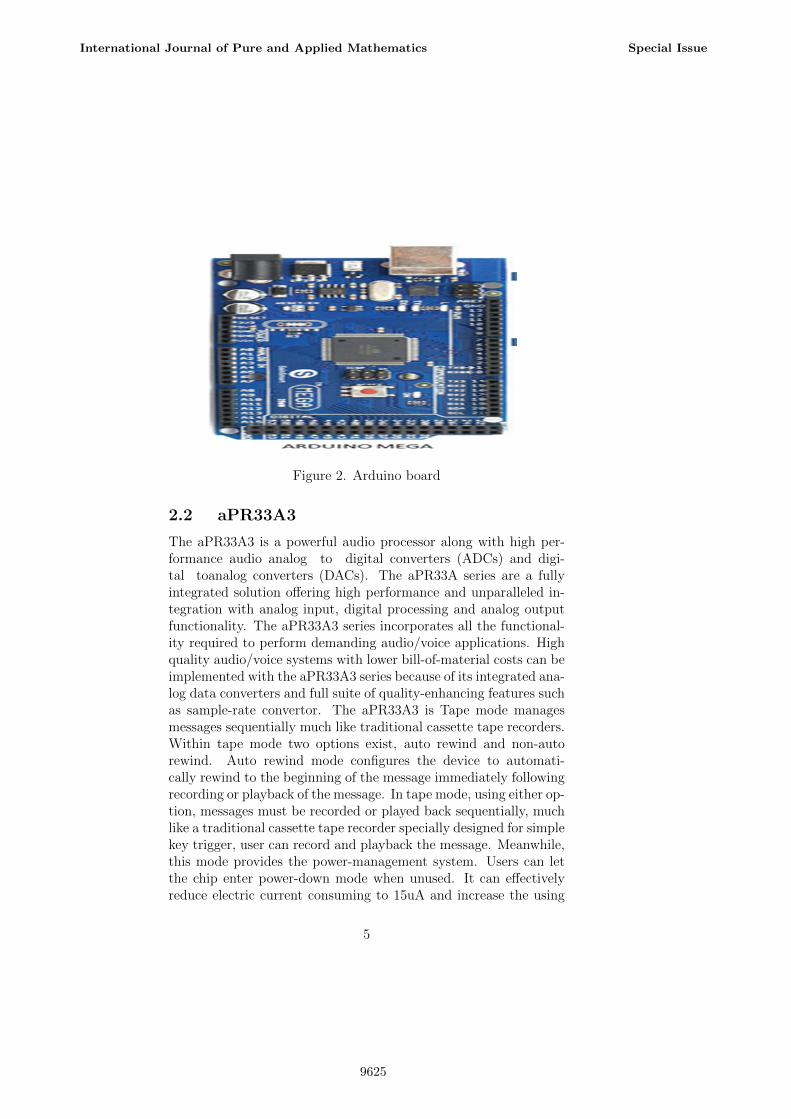
Figure 2. Arduino board
2.2 aPR33A3
The aPR33A3 is a powerful audio processor along with high per-formance audio analog to digital converters (ADCs) and digi-tal toanalog converters (DACs). The aPR33A series are a fullyintegrated solution offering high performance and unparalleled in-tegration with analog input, digital processing and analog outputfunctionality. The aPR33A3 series incorporates all the functional-ity required to perform demanding audio/voice applications. Highquality audio/voice systems with lower bill-of-material costs can beimplemented with the aPR33A3 series because of its integrated ana-log data converters and full suite of quality-enhancing features suchas sample-rate convertor. The aPR33A3 is Tape mode managesmessages sequentially much like traditional cassette tape recorders.Within tape mode two options exist, auto rewind and non-autorewind. Auto rewind mode configures the device to automati-cally rewind to the beginning of the message immediately followingrecording or playback of the message. In tape mode, using either op-tion, messages must be recorded or played back sequentially, muchlike a traditional cassette tape recorder specially designed for simplekey trigger, user can record and playback the message. Meanwhile,this mode provides the power-management system. Users can letthe chip enter power-down mode when unused. It can effectivelyreduce electric current consuming to 15uA and increase the using
5
International Journal of Pure and Applied Mathematics Special Issue
9625
time in any projects powered by batteries.
2.3 Ultrasonic sensor
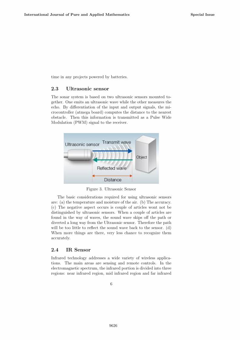
The sonar system is based on two ultrasonic sensors mounted to-gether. One emits an ultrasonic wave while the other measures theecho. By differentiation of the input and output signals, the mi-crocontroller (atmega board) computes the distance to the nearestobstacle. Then this information is transmitted as a Pulse WideModulation (PWM) signal to the receiver.
Figure 3. Ultrasonic Sensor
The basic considerations required for using ultrasonic sensorsare: (a) the temperature and moisture of the air. (b) The accuracy.(c) The negative aspect occurs is couple of articles wont not bedistinguished by ultrasonic sensors. When a couple of articles arefound in the way of waves, the sound wave skips off the path ordiverted a long way from the Ultrasonic sensor. Therefore the pathwill be too little to reflect the sound wave back to the sensor. (d)When more things are there, very less chance to recognize themaccurately.
2.4 IR Sensor
Infrared technology addresses a wide variety of wireless applica-tions. The main areas are sensing and remote controls. In theelectromagnetic spectrum, the infrared portion is divided into threeregions: near infrared region, mid infrared region and far infrared
6
International Journal of Pure and Applied Mathematics Special Issue
9626
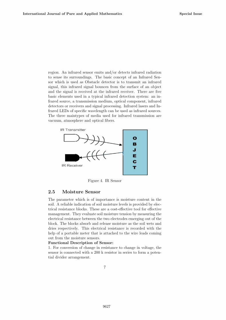
region. An infrared sensor emits and/or detects infrared radiationto sense its surroundings. The basic concept of an Infrared Sen-sor which is used as Obstacle detector is to transmit an infraredsignal, this infrared signal bounces from the surface of an objectand the signal is received at the infrared receiver. There are fivebasic elements used in a typical infrared detection system: an in-frared source, a transmission medium, optical component, infrareddetectors or receivers and signal processing. Infrared lasers and In-frared LEDs of specific wavelength can be used as infrared sources.The three maintypes of media used for infrared transmission arevacuum, atmosphere and optical fibers.
Figure 4. IR Sensor
2.5 Moisture Sensor
The parameter which is of importance is moisture content in thesoil. A reliable indication of soil moisture levels is provided by elec-trical resistance blocks. These are a cost-effective tool for effectivemanagement. They evaluate soil moisture tension by measuring theelectrical resistance between the two electrodes emerging out of theblock. The blocks absorb and release moisture as the soil wets anddries respectively. This electrical resistance is recorded with thehelp of a portable meter that is attached to the wire leads comingout from the moisture sensors.Functional Description of Sensor:1. For conversion of change in resistance to change in voltage, thesensor is connected with a 200 k resistor in series to form a poten-tial divider arrangement.
7
International Journal of Pure and Applied Mathematics Special Issue
9627
2. It gives a voltage output corresponding to the conductivity of thesoil. The conductivity of soil varies depending upon the amount ofmoisture present in it. It increases with increase in the water con-tent of the soil. The higher the water contents of the blocks, thelower the electrical resistance.3. The voltage output is taken from the output terminal of thiscircuit. The moisture sensor is immersed into the specimen soilwhose moisture content is under test.The soil was examined under three conditions.(a) Dry condition: The sensor is placed in the soil under dryconditions and embedded up to a fair depth of the soil. In drycondition, as there is no conduction path between the two copperleads the sensor gives a high resistance value (nearly 700 k). Thevoltage output of the potential divider in this case ranges from 2.2V to lower optimum level (3 V).(b) Optimum condition: When water is added to the soil, itpercolates through the successive layers of it and spreads acrossthe layers of soil due to capillary force. This increases the moisturecontent of the soil. Thus a conductive path is established betweenthe two copper leads. This leads to a decrease in resistance ofsensor. The optimum condition of the soil can be set manually de-pending on the type of soil.(c) Excess wet condition: With the increase in water contentbeyond the optimum level, there is drastic increase in the conduc-tivity of the soil and the sensor resistance is further decreased toaround 50 k. The voltage output of the potential divider in thiscase ranges from upper optimum level (5 V) to 10 V.
2.6 Motor Drive:
L293D is a typical Motor driver or Motor Driver IC which allowsDC motor to drive on either direction. L293D is a 16-pin IC whichcan control a set of two DC motors simultaneously in any direction.It means that you can control two DC motor with a single L293DIC.In a single L293D chip there are two h-Bridge circuit insidethe IC which can rotate two dc motor independently.H-bridge is acircuit which allows the voltage to be flown in either direction.H-bridge IC is ideal for driving a DC motor.Due its size it is very
8
International Journal of Pure and Applied Mathematics Special Issue
9628
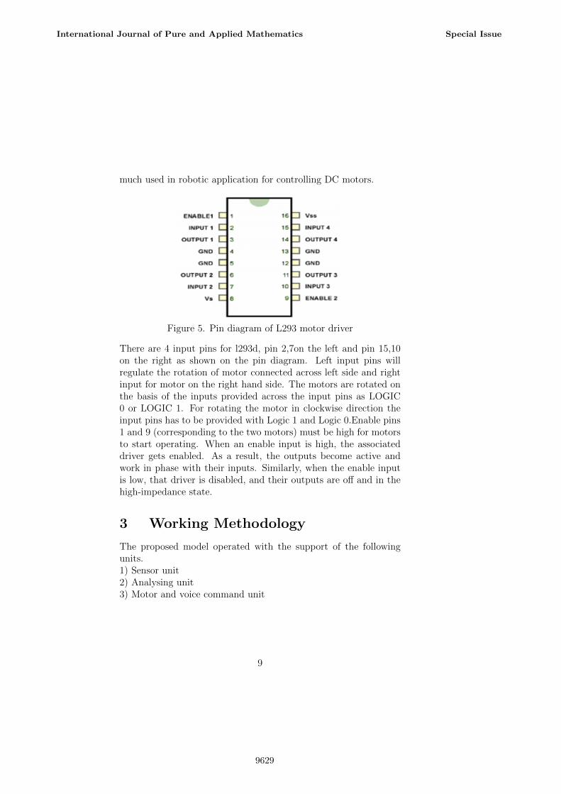
much used in robotic application for controlling DC motors.
Figure 5. Pin diagram of L293 motor driver
There are 4 input pins for l293d, pin 2,7on the left and pin 15,10on the right as shown on the pin diagram. Left input pins willregulate the rotation of motor connected across left side and rightinput for motor on the right hand side. The motors are rotated onthe basis of the inputs provided across the input pins as LOGIC0 or LOGIC 1. For rotating the motor in clockwise direction theinput pins has to be provided with Logic 1 and Logic 0.Enable pins1 and 9 (corresponding to the two motors) must be high for motorsto start operating. When an enable input is high, the associateddriver gets enabled. As a result, the outputs become active andwork in phase with their inputs. Similarly, when the enable inputis low, that driver is disabled, and their outputs are off and in thehigh-impedance state.
3 Working Methodology
The proposed model operated with the support of the followingunits.1) Sensor unit2) Analysing unit3) Motor and voice command unit
9
International Journal of Pure and Applied Mathematics Special Issue
9629
3.1 Sensor unit
: In this unit, the ultrasonic sensor, IR sensor, moisture sensorand GPS module will sense/ detect the obstacles around 180 de-grees, holes or uneven surface of road or footpath, water on streetwhich may slip the visually impaired individual and the area of thevisually impaired person walking.
3.2 Analysing unit
In this unit, the information received from the all the sensors givento micro controller. It analyzes the information and generates re-quired instructions to all other units.
3.3 Motor and voice command unit
In this unit, the information will be received from the microcon-troller. The motor shield will drive the motors as per the instruc-tions given by the micro controller. The voice information will sendto voice module and the voice module will alert blind persons bysending the sound output in the form of buzzer and that will alertthe blind person.
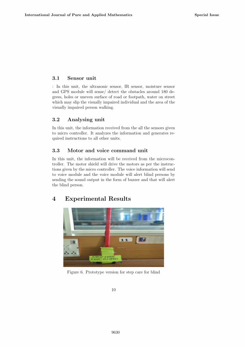
4 Experimental Results
Figure 6. Prototype version for step care for blind
10
International Journal of Pure and Applied Mathematics Special Issue
9630
4.1 Results Analysis
For the presented device we have focused our tests on the accuracyof the measurements and the ability of visually impaired individu-als to keep away from obstacles in a controlled environment. Weverified if the feedback modes can work all together and calibratedthe intensity of the feedback signals such that they have the samemagnitude in both modes. The device was tested in indoor and out-door conditions. It is recommended to use it outdoor conditions, itgives information of the soil is wet. The tests were performed on5 blind folded individuals in various environmental situations. Allthe individuals were able to navigate in the environment and avoidthe obstacles. The most accurate results were obtained with flatsurfaces as obstacles at an angle of maximum 30 from horizontal.Surfaces with irregular shapes can reflect the signals in the vicin-ity of the ultrasonic sensor and the results of the measurement canbe erroneous. This shortcoming can be suppressed by moving thehand both in the horizontal and vertical planes.
4.2 Advantages of Step Care for Blind
1. Automated process.2. Simple design.3. Easy to use.4. Durable.5. Low power consumption.6. Effective navigational assistant.7. Objects and obstacles can be easily detected by sensors.8. Wet, sloppy terrain can be easily identified.9. Easy to walk, observe the way they used to walk.
5 Conclusion
A great deal of exertion has been placed in the electromechanicalplan of this unit passing on the vibrations adequately and guaran-teeing that it is effortlessly append able on the current white stickswithout located help. An urgent plan streamlining objective wasfetched the unit has been created as aminimal effort gadget which is
11
International Journal of Pure and Applied Mathematics Special Issue
9631
reasonable by the poor in creating nations. This stick for blind per-sons uses innovative framework which is used effectively for accom-plishing the target. That can recognize items or obstacles beforeclients and sustains cautioning back, in the types of voice messagesand signal, to clients. This venture is to individuals with inabili-ties that are incognizant in regards to encourage the developmentand increment security. Other than that, we get the advantage forthis venture. This undertaking is a programmed framework thatutilizations ultrasonic sensors to identify the hindrances in frontby a miniaturized scale controller. Including security highlights forthe incapacitated (daze). Encourage the general population withinabilities to move openly. This task will work to help the greaterpart of the visually impaired individuals on the planet to makethem less demanding to walk wherever they need. This task wasdone to help the incognizant in regards to move in front extremelywell.
References
[1] World Health organization (WHO),http://www.who.int/mediacentre/factsheets/fs282/en/,lastaccessed on06.07.2016.
[2] European Blind Union (EBU),http://www.euroblind.org/media/employment/thmoverview-version-3-final-rev-RF Romanian-translation.doc,last accessedon 02.07.2016.
[3] W. Barfield and T. Caudell, Fundamentals of Wearable Com-puters -and Augmented Reality, Lawrence Erlbaum Asso-ciates, Mahwah, NewJersy, 2001, pp. 429-431.
[4] D. Dakopoulos, S. K. Boddhu, and N. Bourbakis, ”A 2D Vibra-tionArray as an Assistive Device for Visually Impaired,” IEEE7thInternational Symposium on BioInformatics and BioEngi-neering,Boston, USA, October 2007, pp. 930-937.
[5] B. Ando, S. Baglio, V. Marletta, and A. Valastro, A HapticSolution toAssist Visually Impaired in Mobility Tasks, IEEE
12
International Journal of Pure and Applied Mathematics Special Issue
9632
Transactions OnHuman-machine Systems, Vol. 45, No. 5, pp.641 646, October 2015.
[6] L.H. Villamizar, M. Gualdron, F. Gonzalez, J. Aceros, andC.V. Rizzo-Sierra, A necklace sonar with adjustable scoperange for assisting thevisually impaired, 35th Annual Inter-national Conference of the IEEEEMBS, Osaka, Japan, 3 - 7July 2013, pp. 1450 1453.
[7] A. Kulkarni, and K. Bhurchandi, Low Cost E-Book ReadingDevice forBlind People, Computing Communication Controland AutomationInternational Conference (ICCUBEA), Pune,Maharashtra, India,February 2015, pp. 2-3.
[8] S. Pundlik, H. Yi H, R. Liu, E. Peli, and G. Luo, Magni-fyingSmartphone Screen using Google Glass for Low-VisionUsers, IEEETransactions on Neural Systems and Rehabilita-tion EngineeringTNSRE-2015-00191, pp. 1 10, March 2016.
[9] S.Nanu,”Educationalaspectsincontrolsystemdesigntechnology,”Scientific and Technical Bulletin, Series: Electrotechnics, Au-tomatic Control and Computer Science UAV Arad, Vol. 4, No1, pp.584-589, 2007.
13
International Journal of Pure and Applied Mathematics Special Issue
9633

9634