Embed Size (px)
Citation preview

STEP-BY-STEP PLANS FOR CONSTRUCTING A 250 STICK ROCKET BARN (RBN 3.0) (see RBR plans for furnace and metal
component construction)
DESIGNED BY PETER SCOTTDESIGN COPYRIGHT PETER SCOTT
MAY 13, 2008
DESIGNED FOR FARMERS WITH MAX FIREWOOD LENGTH
OF 125 CM by 30 CM

Foundation Top View
Rocket Barn Foundation = 440cm by 390cm Internal dimensions
Brick Chimney foundation = 70 by 70 cm internal dimensions. Centered on narrow side of barn
Diagonal measurements = 588cm
Door opening is :
•75 cm wide
•155 cm from the edge of the foundation
•on the same wall as the furnace opening
Note: If possible the foundation should be set on a flat ,well drained ground
STEP 1 FOUNDATION
Furnace opening is 90 cm wide and set 33 cm from foundation edge
All dimensions are internal!

Excavation for Furnace Foundation
…except under the furnace where the foundation must be 59 cm deep (approx 2 courses under furnace opening)
*The foundation depth will vary depending on the slope of ground but it must be at least 30 cm deep
All dimensions are internal!STEP 2 FOUNDATION (2)
The entire foundation should be 30 cm wide and a minimum of 30 cm deep* ….
Cross-sectional furnace _door side view
The furnace opening begins 33 cm from the foundation edge and is 90 cm wide and 44 cm deep
Furnace Foundation
Foundation ¾ front View

The internal dimensions chimney foundation are 70 cm by 70 cm
Foundation side view
STEP 3 FOUNDATION (3)
The furnace opening begins 33 cm from the foundation edge and is 90 cm wide and 44 cm deep
interlock the chimney foundation into the wall foundation!
Foundation ¾ front View
Door opening is :
•75 cm wide
•155 cm from the edge of the foundation
•on the same wall as the furnace opening
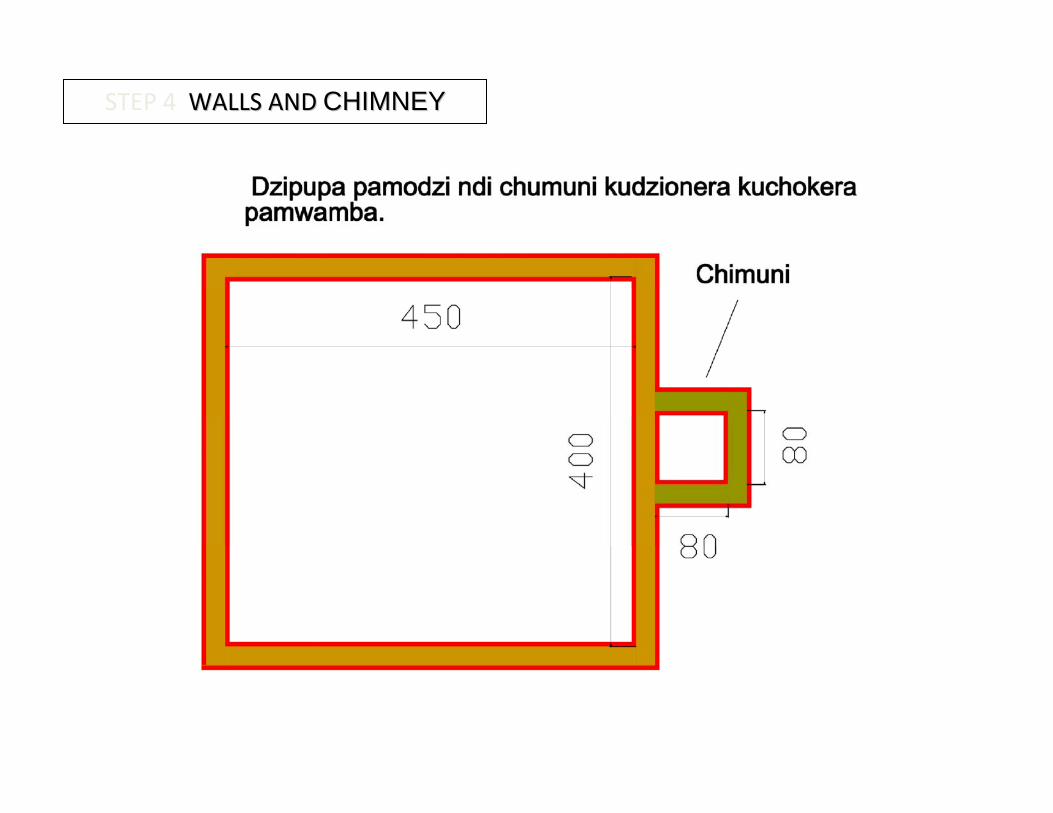
STEP 4 WALLS AND WALLS AND CHIMNEYCHIMNEY

For strength interlock the barn and chimney walls
Chimney wall internal dimensions = 80 cm by 80 cm
Chimney wall height = 270 cm
Chimney ¾ back view
Chimney and wall side view
Chimney Top view
29
STEP 5 WALLS AND CHIMNEY WALLS AND CHIMNEY

Note wall height = 330 cm
Chimney height = 270 cm high
Chimney width = 80 cm by 80 cm
Door opening begins 155 cm from foundation edge . The Door opening is 75 cm wide by 175 cm high
Wall dimensions 400 cm wide and 450 cm long
Interlock chimney wall to the barn wall
Wall and chimney ¾ view
STEP 5 WALLS AND CHIMNEY WALLS AND CHIMNEY

STEP 33 WALL SLOPE
2. Construct the barn walls so that the furnace side is 330 cm high and the chimney side is 375 cm high.
270
160 Walls side viewWalls side view
Walls ¾ back view

STEP 6 WALLS INITIAL
1. Chimney. Note that the chimney interlocks int othethe barn wall
1. Door opening : 160 cm from rear wall corner
1. Furnace opening on same side as door
1. Air vent begins 2 courses above foundation . Number of openings ( 8,10,12) will depend on size of bricks used
160 cm

1. Mark the center point of the front wall, above the foundation. With 20 cm thick walls, the center point will be 220 cm from the outside corner wall
2. Make six 10 cm by cm openings ( at 10 cm intervals) to the right and the left of the centre point. This will make a total of 12 openings. See following page for spacing with non standard bricks
STEP 6AFRONT AIR VENTS
Front wall 3/4 view
Front wall , front view32
Note: the air vents are placed on the wall adjacent to the new furnace opening
2 courses

STEP 6B FRONT AIR VENTS (for non-standard brick sizes)
1012
15
If the height of the 3rd
course is 12 cm, make a total of ten air intakes (10 * 12 cm by 10 cm)
If the height of the course is 15cm, make a total of eight air intakes (8 * 15cm by 10 cm
If the height of the 3rd
course is 10 cm make a total of twelve air intakes ( 12 * 10 cm by 10 cm)
4th
3rd
If non standard brick sizes are used then this will change the number and size of the air vents will change. The width of the opening will always be 10 cm
Be sure that each brick on the fourth course is properly supported by the two bricks on the 3rd
course

STEP 7 FIRE BOX OUTLET/CHIMNEY INTERFACE
1. Find the center point of the inside back wall (200 cm)
Back wall front view
Barn ¾ front view
33
2. From the centre point measure 8 cm (a minimum of 1 course) up from the foundation.
3. Centered above the 8 cm mark, cut a 30 by 30 cm opening into the back wall

STEP 8 BARN OUTLET / CHIMNEY INTERFACE
34
Barn ¾ front view
Back wall front view
1. Make a mark 120 cm up from the foundation centre point on the inside of the back wall
2. From this centre point measure 80 cm wide and 150 cm high
3. The new opening is flush with the inner walls of the chimney
4. To make the lintel for the outlet use timber treated with used motor oil to prevent termite infestation

STEP 9 FRONT VIEW WINDOW
1. Mark the center point of the front wall, 140 cmabove the foundation
2. Centered above the 140 cm mark, leave a 40 cm by 40 cm opening into the front wall
Front wall 3/4 view
37
Instead of building the wall and then cutting hole, better to build window as you build the wall

STEP 10 REAR VIEW WINDOW
1. Mark 140 cm above the foundation and 50 cm out from the chimney
2. From this point, make a 40cm by 40cm opening
3. After cutting the opening install the view window
The rear view window should be placed on the rear wall near the corner that is farthest from the barn door.

STEP 11 FIREBOXES (1)
3. Assuming that 10 cm wide bricks are used then the total firebox width will be 50 cm (30cm + 10cm + 10cm)
1. The openings between the fireboxes are 40 cm* wide (assuming standardized bricks). With larger bricks, the 40 cm opening will be reduced.
Keep the distance between the firebox and protector wall and firebox and rear wall equal. See next page to calculate …
2. The openings inside each firebox is 30 cm wide. This can not change.
Fireboxes top view

STEP 12 FIREBOXES (2)
2. From that distance subtract 200 cm for the 4 fireboxes which are each 50 cm wide
1. The distance from the rear wall to the furnace protector wall should be 344 cm
4. Take the remaining distance and divide by 2. This will give you the correct distance from the furnace protector wall to the first firebox and the distance from the back wall to the last fire box
3. subtract 120cm for the openings betweenthe fireboxes. There are 3 openings each of which are 40 cm wide* (see step 1 page 39)
Space between firebox edge and side wall= 20 cm
if the measurement from step 1 is 344 cm.. -200 (for fireboxes) -120 (for openings between fireboxes) = 24. Divide by 2 = 12 cm Gap from firebox edge = 12 cm
Fireboxes top view
Furnace/walls top view
12 cm12 cm
Fireboxes 3/4 view
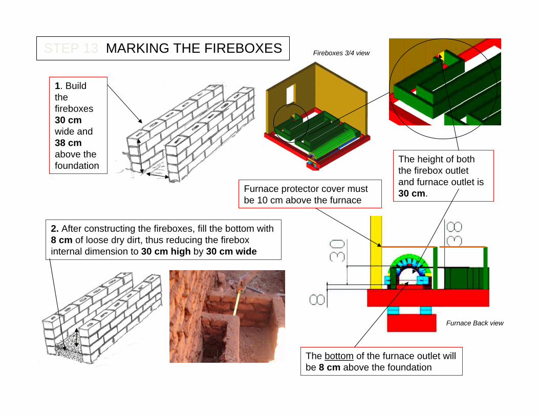
STEP 13 MARKING THE FIREBOXES
1. Build the fireboxes 30 cmwide and 38 cmabove the foundation
2. After constructing the fireboxes, fill the bottom with 8 cm of loose dry dirt, thus reducing the firebox internal dimension to 30 cm high by 30 cm wide
The height of both the firebox outlet and furnace outlet is 30 cm.
The bottom of the furnace outlet will be 8 cm above the foundation
Fireboxes 3/4 view
Furnace Back view
Furnace protector cover must be 10 cm above the furnace

2. For the rest of the fireboxes use a minimum of 28 gauge (grey). Take five 180 cm by 77 cm flat sheets and cut them in half lengthwise to make ten 38.5 cm by 180 cm sections
STEP 14A METAL FLAT SHEET
Note: Two types of metal flat sheet are required for covering the fireboxes - 24 and 28 gauge
2. Near the furnace outlet use 24 gauge mild steel sheet (purple)
1. After filling the fireboxes with 8 cm of loose dry dirt, cover them with the metal flat sheet
Fireboxes 3/4 view 38

STEP 14B METAL FLAT SHEET
1. The first sheet is placed under the thinner metal. This underlap is continued to the end of the fireboxes: the sheet closer to the furnace is placed under the sheet that is farther from the furnace
2. Where the metal sheet meets the furnace -reinforce with bricks and matope, not just matope. This is the most vulnerable point in the barn!
Note: the heavy gauge sheet is cut so as to fit tightly against the furnace exit
Furnace Back view

STEP 15 FURNACE PROTECTOR AND SUPPORTING WALL
1. Construct the furnace protector supporting wall 5 cm from the edge of the furnace
2. The wall and the protector must be 10 cm higher than the top of the furnace
3. Use bamboo or thin tier poles for the furnace protector. Space poles so that air will pass through but tobacco will not.
The furnace protector must extend so as to cover as much of the heavy gauge sheet metal firebox as possible!
New: In order to further reduce fire hazard, an additional wall and fire box protector (removable) should be added here
Furnace protector back view internal

3. Then place the third set of tiers 75 cm above the second. This should create a 10 cm gap between the third tier pole and the ceiling
170
STEP 16 TIER POLES
Walls ¾ front view internal
Note: the red tiers at the back of the barn are supported on posts. These 3 tiers do not enter into the barn wall. This reduces stress on the corner walls
1. Place the first set of tiers 170cm above the foundation
2. Then place the second set of tiers 75 cm above the first
Supporting tiers on posts (instead of in the wall) reduces stress and cracking at the corners

330
STEP 17 HORIZONTAL TIER SPACING
Walls side view
Horizontal tier spacing is 110 cm (on center).
110 110 110 110

STEP 35 CEILING
STEP 36 ROOF JOISTS
1. The ceiling tier poles are placed on top of the 330 cm high wall. Bamboos (or thin tier poles/ branches) are then laid on top of the bamboo
The first course of joists requires 4 poles (green) laid lengthwise
The second course of joists are laid perpendicular tothe first course and require 5 poles (purple)
There should be an approximate 40 cm overhang around all 4 walls to support the iron sheeting

STEP 37 INSULATING WITH GRASS
1. Pack grass 15 cm thick (approx 40 bundles) between the roof joists and the bamboo. No plastic or cardboard is needed.
2. Tightly pack grass (15 cm thick) on top of the bamboo. Seal all gaps to prevent air or light leaks

STEP 39 WOOD SHELTER
Wood preparation:To decrease wood consumption, cut and split wood at the beginning of the dry season and then store the wood, covered, just before the first rains
2. Use grass (or scrap metal if desired) to cover the shelter
This shelter will provide enough shelter for approximately 10 cubic meters of wood. If more shelter is required then the width can be extended from 150 cm to 300 cm to cover 2 stacks of wood
1. Take the 6 poles and bury them so that the back 3 poles are against the wall and 250 cm high and the front 3 poles are 150 cm away from the wall and 210 cm high
For increased strength, the top of the posts should be connected to the second set of tier poles that protrude from the barn wall