Embed Size (px)
Citation preview
STEP-BY-STEP INSTRUCTIONS ONTEMPORARY ABUTMENTS
Straumann® Temporary Abutments, VITA CAD-Temp®

The ITI (International Team for Implantology) is academic partner of Institut Straumann AG in the areas of research and education.
1
CONTENTS
Temporary abutments
1. Temporary abutment Wide Neck (WN) – Polymer with titanium alloy inlay 2 WN is used to represent Tissue Level lines. Instructions shown are applicable to all Tissue Level examples.
1.1. Prosthetic procedure for temporary abutment WN 3
2. Temporary abutment Regular Crossfit® (RC) – Polymer with titanium alloy inlay 9 RC is used to represent Bone Level lines. Instructions shown are applicable to all Bone Level examples.
2.1. Prosthetic procedure for temporary abutment RC 10
These instructions are applicable to RN, WN, RC, NC and NNC.
2
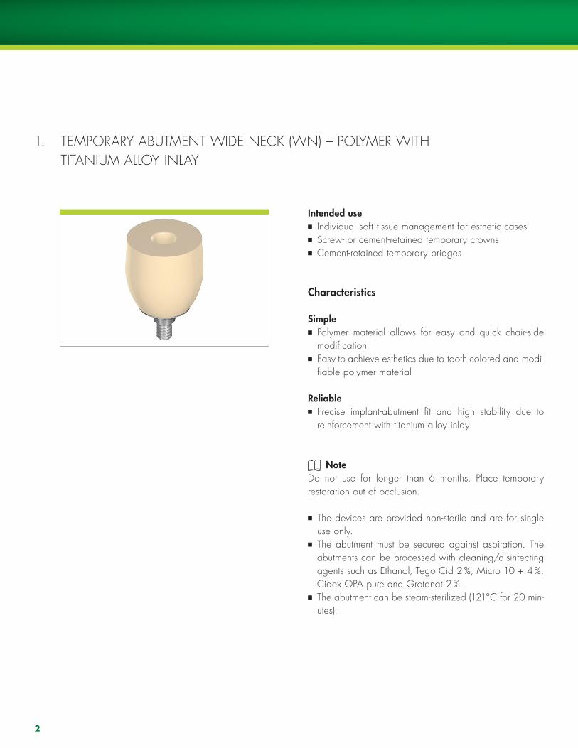
1. TEmPORARY ABUTmENT WIDE NECK (WN) – POlYmER WITh TITANIUm AllOY INlAY
Intended use Individual soft tissue management for esthetic cases Screw- or cement-retained temporary crowns Cement-retained temporary bridges
Characteristics
Simple Polymer material allows for easy and quick chair-side modification
Easy-to-achieve esthetics due to tooth-colored and modi-fiable polymer material
Reliable Precise implant-abutment fit and high stability due to reinforcement with titanium alloy inlay
Note Do not use for longer than 6 months. Place temporary restoration out of occlusion.
The devices are provided non-sterile and are for single use only.
The abutment must be secured against aspiration. The abutments can be processed with cleaning/disinfecting agents such as Ethanol, Tego Cid 2 %, micro 10 + 4 %, Cidex OPA pure and Grotanat 2 %.
The abutment can be steam-sterilized (121°C for 20 min-utes).
3
1.1. PROSThETIC PROCEDURE FOR TEmPORARY ABUTmENT WN
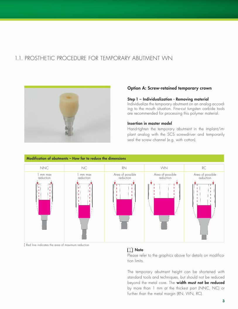
Option A: Screw-retained temporary crown
Step 1 – Individualization - Removing materialIndividualize the temporary abutment on an analog accord-ing to the mouth situation. Fine-cut tungsten carbide tools are recommended for processing this polymer material.
Insertion in master modelhand-tighten the temporary abutment in the implant/im-plant analog with the SCS screwdriver and temporarily seal the screw channel (e.g. with cotton).
Modification of abutments – How far to reduce the dimensions
NNC NC RN WN RC
Note Please refer to the graphics above for details on modifica-tion limits.
The temporary abutment height can be shortened with standard tools and techniques, but should not be reduced beyond the metal core. The width must not be reduced by more than 1 mm at the thickest part (NNC, NC) or further than the metal margin (RN, WN, RC).
1 mm maxreduction
1 mm maxreduction
Area of possiblereduction
Area of possiblereduction
Area of possiblereduction
Red line indicates the area of maximum reduction
4
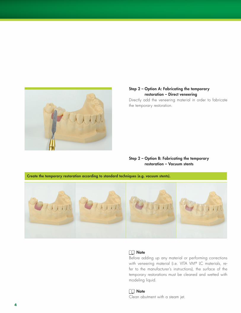
Step 2 – Option A: Fabricating the temporary restoration – Direct veneeringDirectly add the veneering material in order to fabricate the temporary restoration.
Step 2 – Option B: Fabricating the temporary restoration – Vacuum stents
NoteBefore adding up any material or performing corrections with veneering material (i.e. VITA Vm® lC materials, re-fer to the manufacturer’s instructions), the surface of the temporary restorations must be cleaned and wetted with modeling liquid.
NoteClean abutment with a steam jet.
Create the temporary restoration according to standard techniques (e.g. vacuum stents).
5
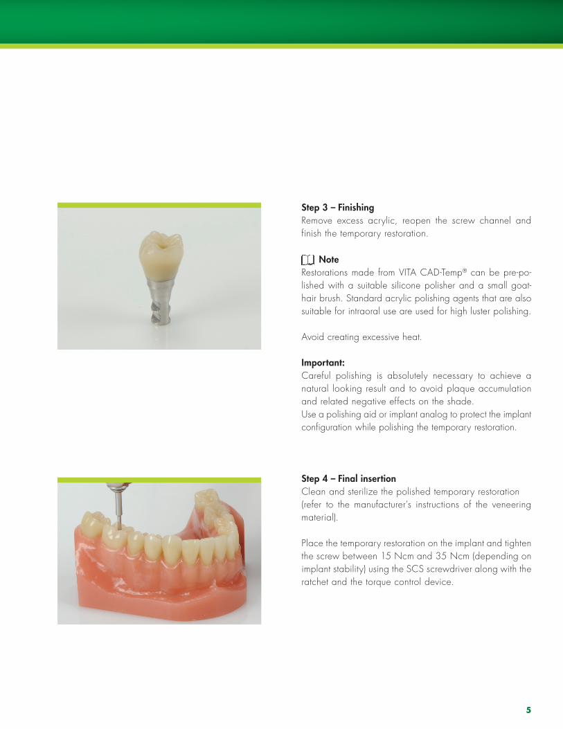
Step 3 – FinishingRemove excess acrylic, reopen the screw channel and finish the temporary restoration.
NoteRestorations made from VITA CAD-Temp® can be pre-po-lished with a suitable silicone polisher and a small goat-hair brush. Standard acrylic polishing agents that are also suitable for intraoral use are used for high luster polishing.
Avoid creating excessive heat.
Important:Careful polishing is absolutely necessary to achieve a natural looking result and to avoid plaque accumulation and related negative effects on the shade. Use a polishing aid or implant analog to protect the implant configuration while polishing the temporary restoration.
Step 4 – Final insertionClean and sterilize the polished temporary restoration (refer to the manufacturer’s instructions of the veneering material).
Place the temporary restoration on the implant and tighten the screw between 15 Ncm and 35 Ncm (depending on implant stability) using the SCS screwdriver along with the ratchet and the torque control device.
6
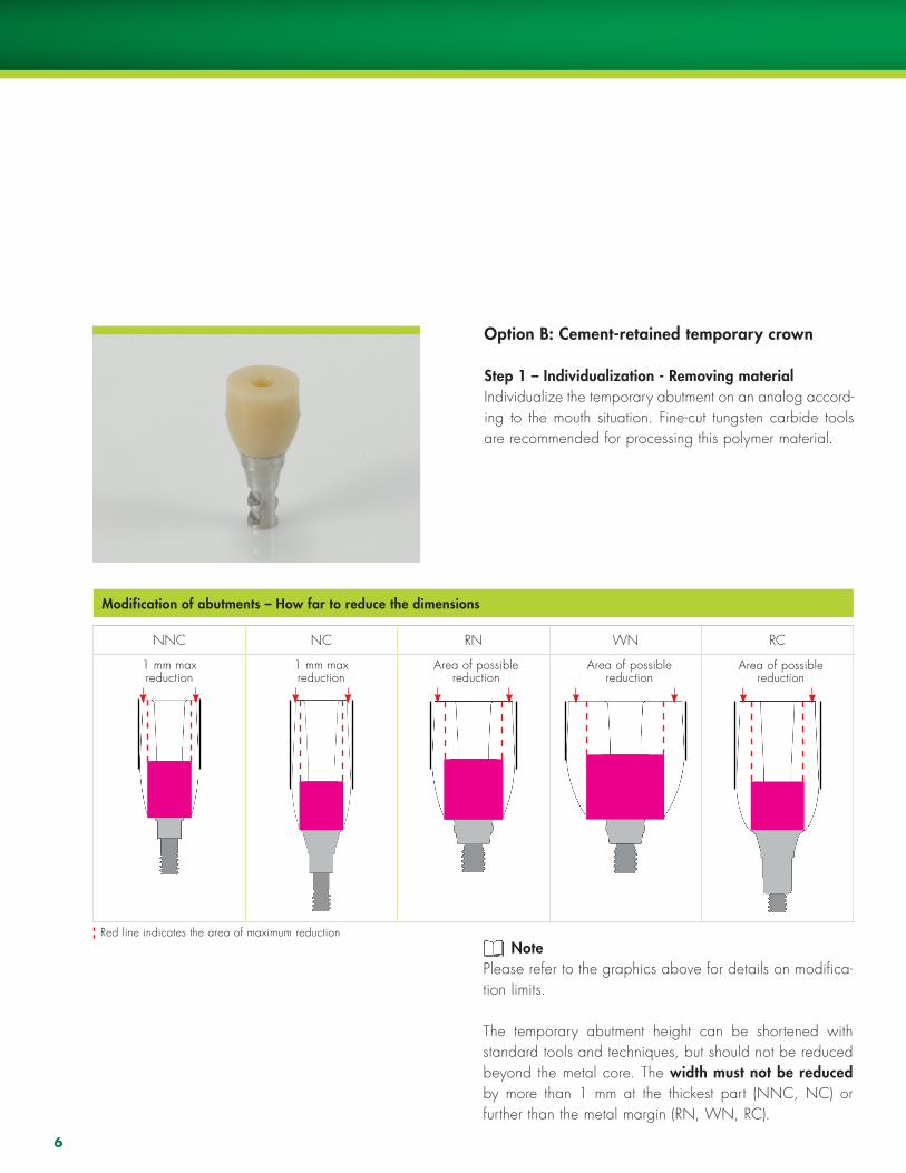
Option B: Cement-retained temporary crown
Step 1 – Individualization - Removing materialIndividualize the temporary abutment on an analog accord-ing to the mouth situation. Fine-cut tungsten carbide tools are recommended for processing this polymer material.
Modification of abutments – How far to reduce the dimensions
NNC NC RN WN RC
1 mm maxreduction
1 mm maxreduction
Area of possiblereduction
Area of possiblereduction
Area of possiblereduction
Red line indicates the area of maximum reduction Note
Please refer to the graphics above for details on modifica-tion limits.
The temporary abutment height can be shortened with standard tools and techniques, but should not be reduced beyond the metal core. The width must not be reduced by more than 1 mm at the thickest part (NNC, NC) or further than the metal margin (RN, WN, RC).
7
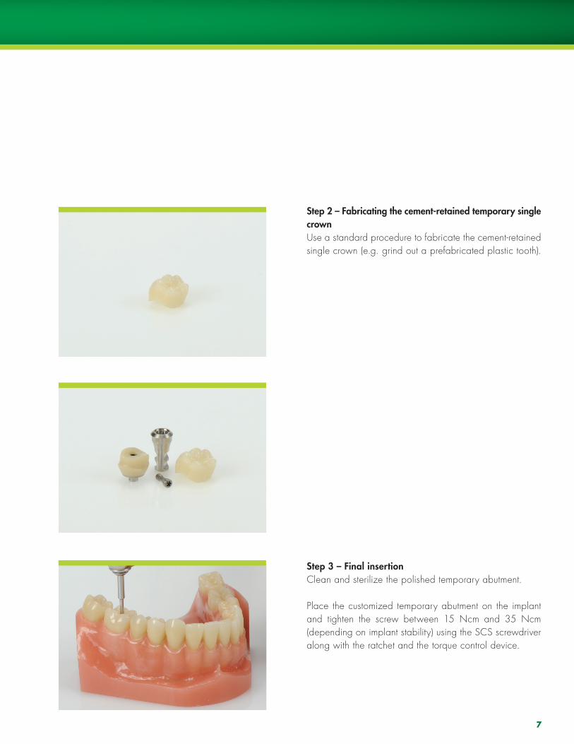
Step 2 – Fabricating the cement-retained temporary single crownUse a standard procedure to fabricate the cement-retained single crown (e.g. grind out a prefabricated plastic tooth).
Step 3 – Final insertionClean and sterilize the polished temporary abutment.
Place the customized temporary abutment on the implant and tighten the screw between 15 Ncm and 35 Ncm (depending on implant stability) using the SCS screwdriver along with the ratchet and the torque control device.
8
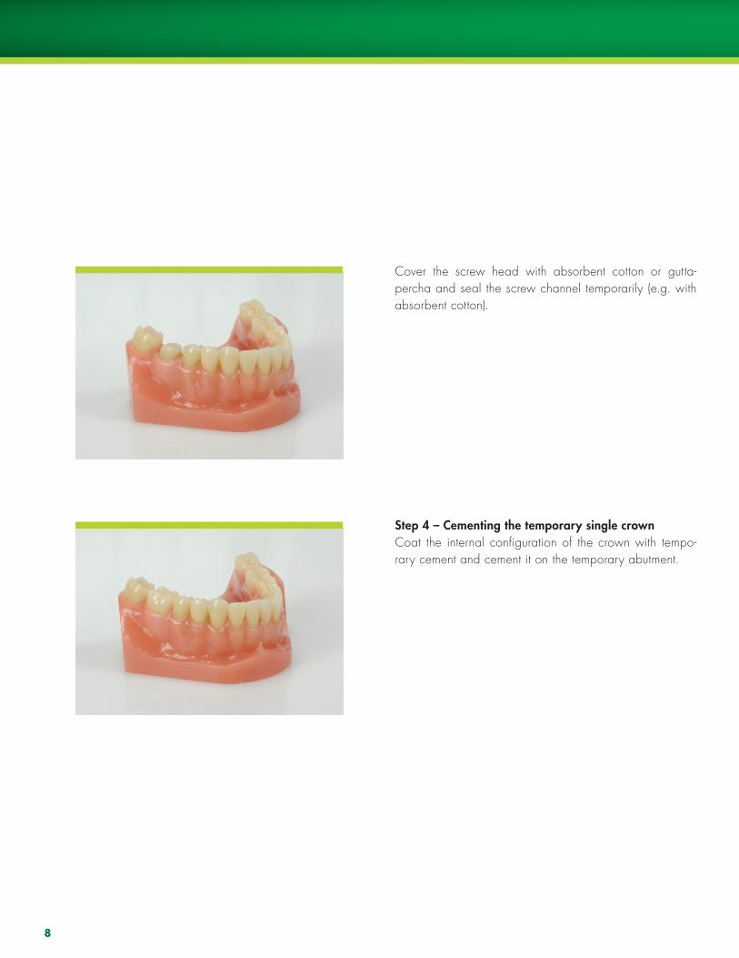
Cover the screw head with absorbent cotton or gutta-percha and seal the screw channel temporarily (e.g. with absorbent cotton).
Step 4 – Cementing the temporary single crownCoat the internal configuration of the crown with tempo-rary cement and cement it on the temporary abutment.
9
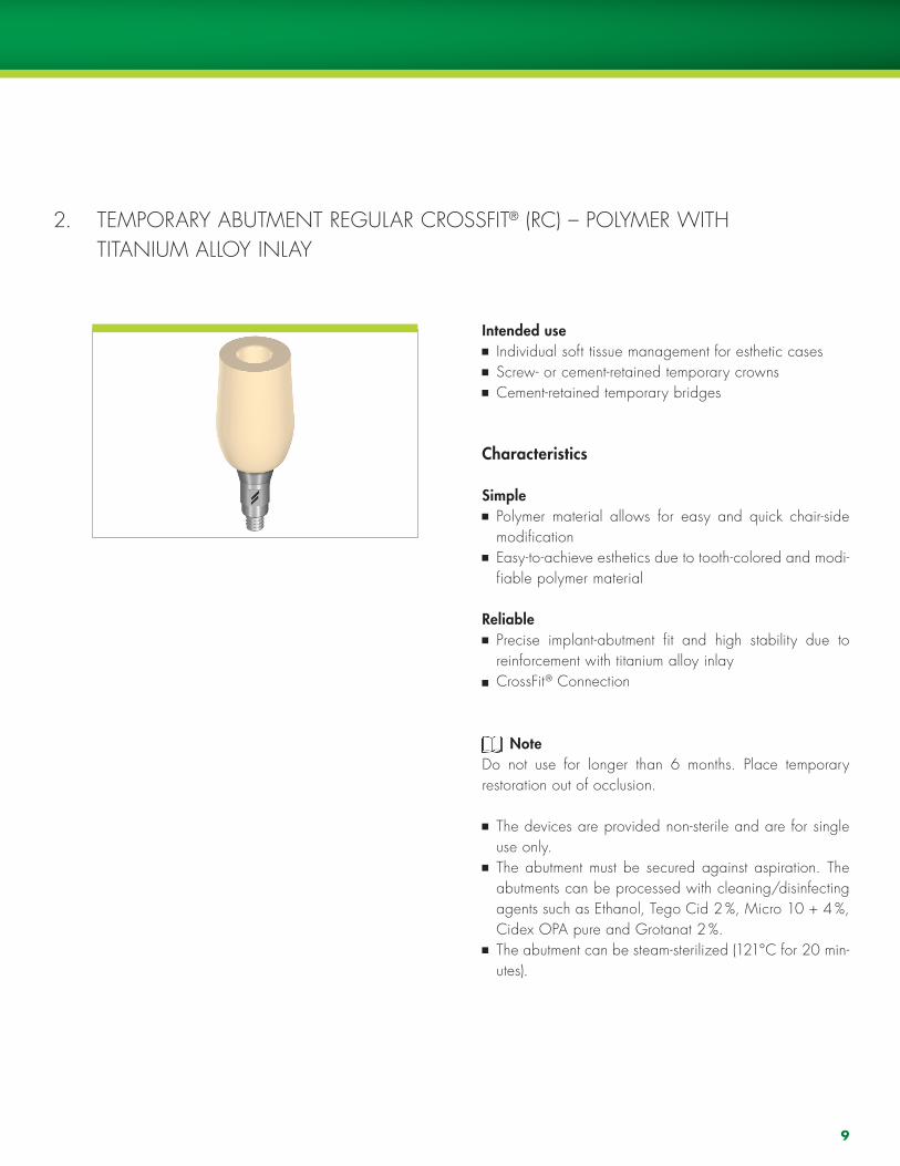
2. TEmPORARY ABUTmENT REGUlAR CROSSFIT® (RC) – POlYmER WITh TITANIUm AllOY INlAY
Intended use Individual soft tissue management for esthetic cases Screw- or cement-retained temporary crowns Cement-retained temporary bridges
Characteristics
Simple Polymer material allows for easy and quick chair-side modification
Easy-to-achieve esthetics due to tooth-colored and modi-fiable polymer material
Reliable Precise implant-abutment fit and high stability due to reinforcement with titanium alloy inlay
CrossFit® Connection
Note Do not use for longer than 6 months. Place temporary restoration out of occlusion.
The devices are provided non-sterile and are for single use only.
The abutment must be secured against aspiration. The abutments can be processed with cleaning/disinfecting agents such as Ethanol, Tego Cid 2 %, micro 10 + 4 %, Cidex OPA pure and Grotanat 2 %.
The abutment can be steam-sterilized (121°C for 20 min-utes).
10
2.1. PROSThETIC PROCEDURE FOR TEmPORARY ABUTmENT RC
Option A: Screw-retained temporary crown
Step 1 – Individualization - Removing materialIndividualize the temporary abutment on an analog accord-ing to the mouth situation. Fine-cut tungsten carbide tools are recommended for processing this polymer material.
Insertion in master modelhand-tighten the temporary abutment in the implant/im-plant analog with the SCS screwdriver and temporarily seal the screw channel (e.g. with cotton).
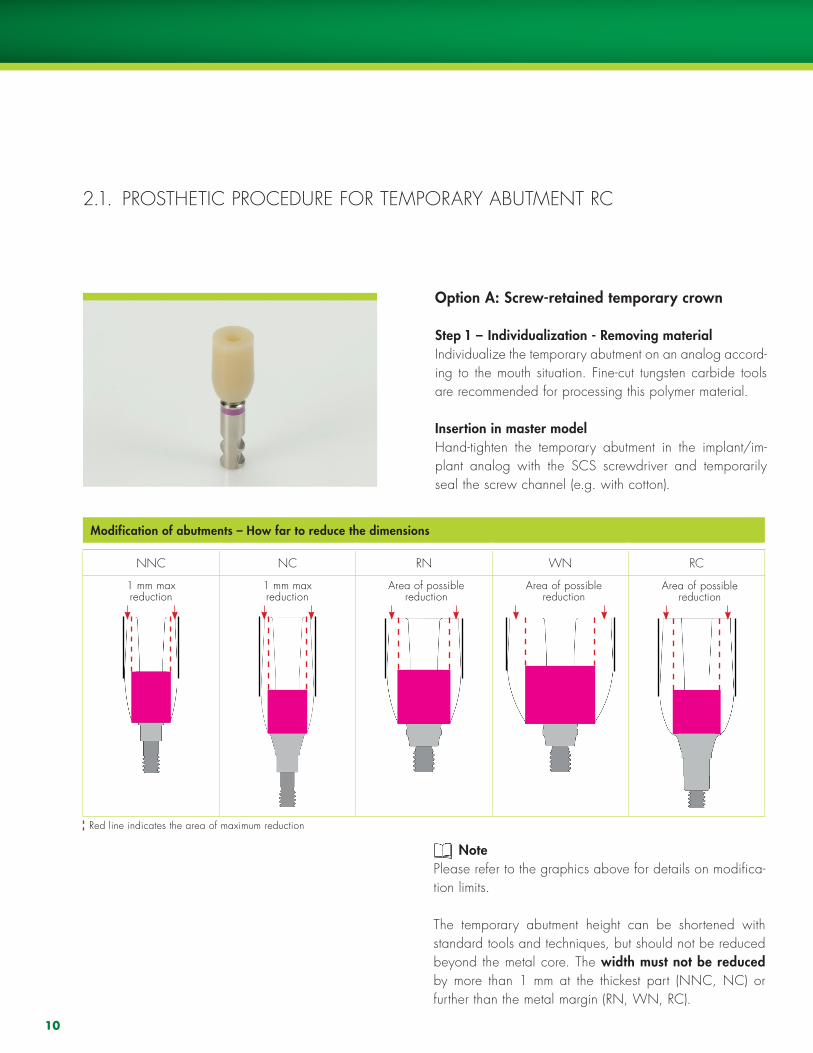
Modification of abutments – How far to reduce the dimensions
NNC NC RN WN RC
1 mm maxreduction
1 mm maxreduction
Area of possiblereduction
Area of possiblereduction
Area of possiblereduction
Red line indicates the area of maximum reduction
Note Please refer to the graphics above for details on modifica-tion limits.
The temporary abutment height can be shortened with standard tools and techniques, but should not be reduced beyond the metal core. The width must not be reduced by more than 1 mm at the thickest part (NNC, NC) or further than the metal margin (RN, WN, RC).
11
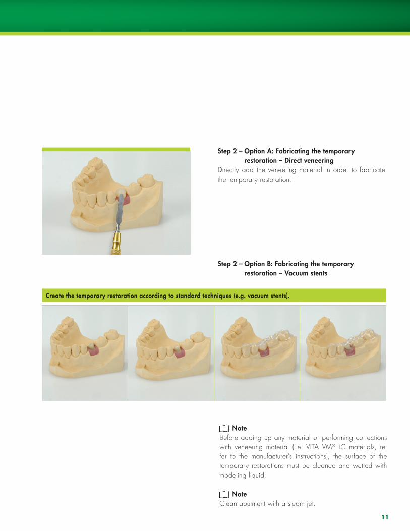
Step 2 – Option A: Fabricating the temporary restoration – Direct veneeringDirectly add the veneering material in order to fabricate the temporary restoration.
Step 2 – Option B: Fabricating the temporary restoration – Vacuum stents
NoteBefore adding up any material or performing corrections with veneering material (i.e. VITA Vm® lC materials, re-fer to the manufacturer’s instructions), the surface of the temporary restorations must be cleaned and wetted with modeling liquid.
NoteClean abutment with a steam jet.
Create the temporary restoration according to standard techniques (e.g. vacuum stents).
12
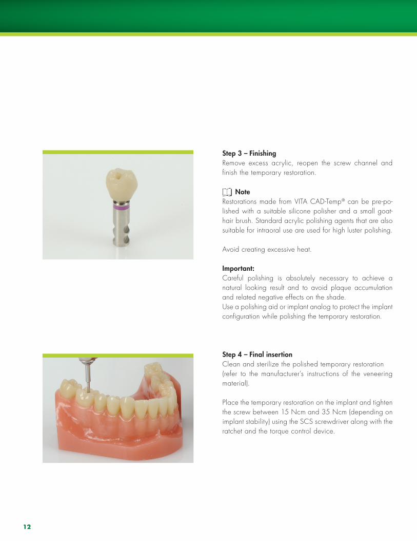
Step 3 – FinishingRemove excess acrylic, reopen the screw channel and finish the temporary restoration.
NoteRestorations made from VITA CAD-Temp® can be pre-po-lished with a suitable silicone polisher and a small goat-hair brush. Standard acrylic polishing agents that are also suitable for intraoral use are used for high luster polishing.
Avoid creating excessive heat.
Important:Careful polishing is absolutely necessary to achieve a natural looking result and to avoid plaque accumulation and related negative effects on the shade. Use a polishing aid or implant analog to protect the implant configuration while polishing the temporary restoration.
Step 4 – Final insertionClean and sterilize the polished temporary restoration (refer to the manufacturer’s instructions of the veneering material).
Place the temporary restoration on the implant and tighten the screw between 15 Ncm and 35 Ncm (depending on implant stability) using the SCS screwdriver along with the ratchet and the torque control device.
13
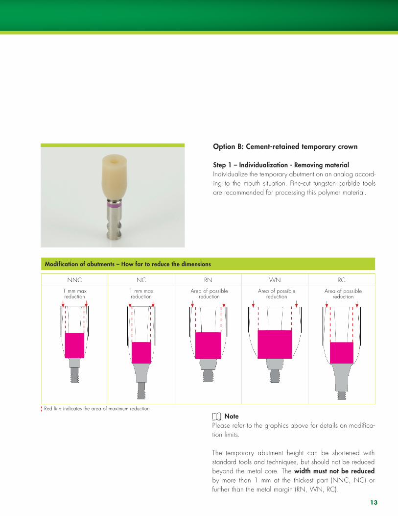
Option B: Cement-retained temporary crown
Step 1 – Individualization - Removing materialIndividualize the temporary abutment on an analog accord-ing to the mouth situation. Fine-cut tungsten carbide tools are recommended for processing this polymer material.
Modification of abutments – How far to reduce the dimensions
NNC NC RN WN RC
1 mm maxreduction
1 mm maxreduction
Area of possiblereduction
Area of possiblereduction
Area of possiblereduction
Red line indicates the area of maximum reduction
Note Please refer to the graphics above for details on modifica-tion limits.
The temporary abutment height can be shortened with standard tools and techniques, but should not be reduced beyond the metal core. The width must not be reduced by more than 1 mm at the thickest part (NNC, NC) or further than the metal margin (RN, WN, RC).
14
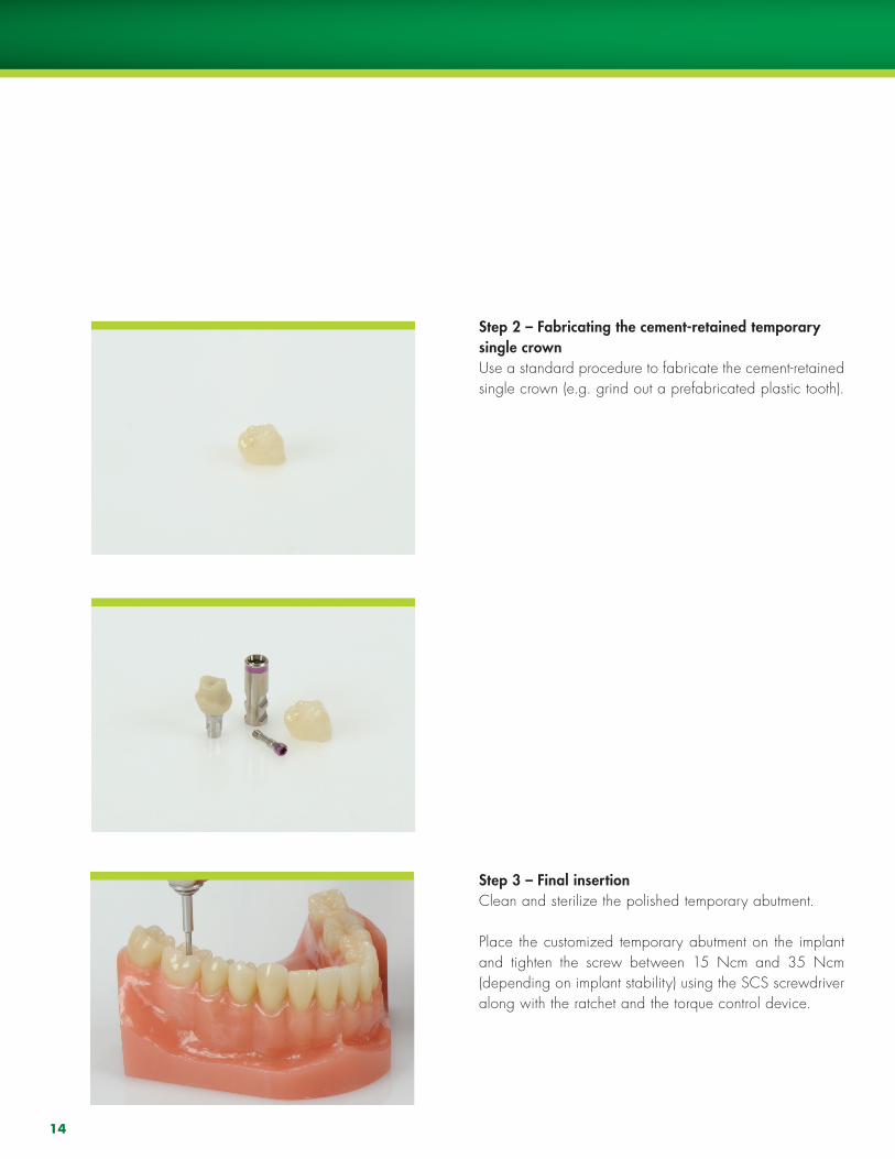
Step 2 – Fabricating the cement-retained temporary single crownUse a standard procedure to fabricate the cement-retained single crown (e.g. grind out a prefabricated plastic tooth).
Step 3 – Final insertionClean and sterilize the polished temporary abutment.
Place the customized temporary abutment on the implant and tighten the screw between 15 Ncm and 35 Ncm (depending on implant stability) using the SCS screwdriver along with the ratchet and the torque control device.
15
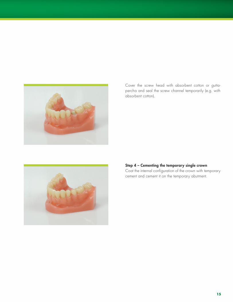
Cover the screw head with absorbent cotton or gutta-percha and seal the screw channel temporarily (e.g. with absorbent cotton).
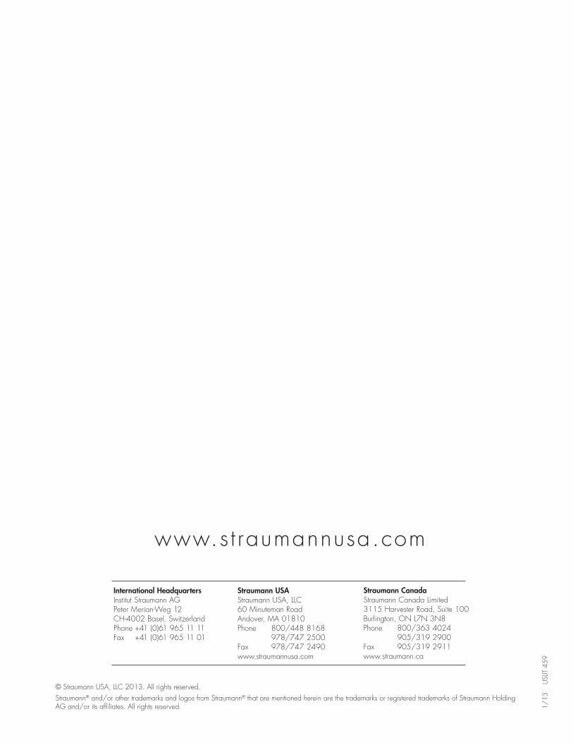
Step 4 – Cementing the temporary single crownCoat the internal configuration of the crown with temporary cement and cement it on the temporary abutment.
www.s t raumannusa.com
International HeadquartersInstitut Straumann AG Peter merian-Weg 12Ch-4002 Basel, SwitzerlandPhone +41 (0)61 965 11 11Fax +41 (0)61 965 11 01
Straumann USAStraumann USA, llC 60 minuteman Road Andover, mA 01810 Phone 800/448 8168 978/747 2500 Fax 978/747 2490 www.straumannusa.com
Straumann CanadaStraumann Canada limited 3115 harvester Road, Suite 100Burlington, ON l7N 3N8 Phone 800/363 4024 905/319 2900 Fax 905/319 2911 www.straumann.ca
1/13
U
SlIT
459
© Straumann USA, llC 2013. All rights reserved. Straumann® and/or other trademarks and logos from Straumann® that are mentioned herein are the trademarks or registered trademarks of Straumann holding AG and/or its affiliates. All rights reserved.