Embed Size (px)
Citation preview

STEP-BY-STEP INSTRUCTIONS FOR BUILDING A MICHELSON
INTERFEROMETER
TECHSPEC® Optical Cage System
PROPRIETARY - Property of Edmund Optics, Inc. | 2012 Copyright© Edmund Optics, Inc.
INTRODUCTION 2
What is a Michelson Interferometer? • A Michelson Interferometer is a simple interferometric design involving a coherent light source,
beamsplitter, and two mirrors. The design first splits the coherent source using the beam splitter. The two beams then travel slightly different distances before reflecting off the mirrors and returning into the beam splitter, where the two beams then recombine. If the difference between the two beams’ path lengths is less than the coherence length of the source, then interference fringes will be generated. Because the coherence length of a source can be extremely short, precision components and alignment are crucial, but often difficult to achieve.
Why TECHSPEC Optical Cage System? • The TECHSPEC Optical Cage System is an ideal solution for creating a Michelson
Interferometer. Because the cage system rods support the basic structure, the only additional alignment needed is correcting the tip-tilt of the optics, and adjusting the difference in distance between the two mirrors and the beamsplitter. The TECHSPEC Optical Cage System allows for the easy adjustment of all parameters, whether it is the use of a linear micrometer for adjusting the path length difference, or a three knob tip-tilt mount to align the mirrors. Building a similar interferometer from standard optical mounting components would be cumbersome and require significantly more parts. The TECHSPEC Optical Cage System offers a compact, user friendly solution.
PROPRIETARY - Property of Edmund Optics, Inc. | 2012 Copyright© Edmund Optics, Inc.
OVERVIEW 3
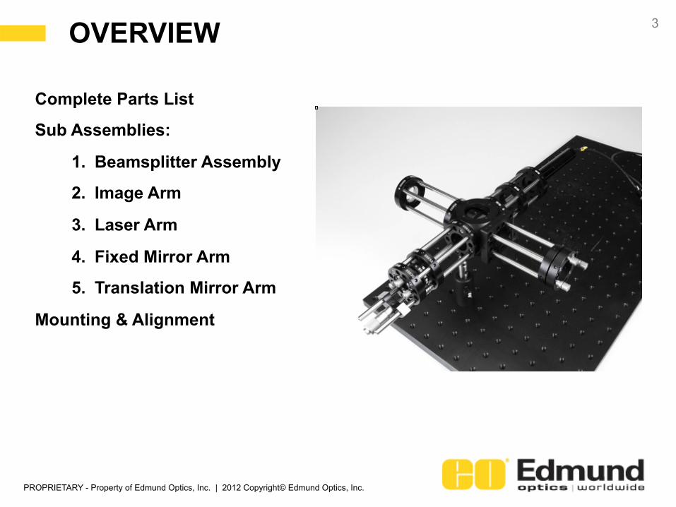
Complete Parts List
Sub Assemblies:
1. Beamsplitter Assembly
2. Image Arm
3. Laser Arm
4. Fixed Mirror Arm
5. Translation Mirror Arm
Mounting & Alignment

PROPRIETARY - Property of Edmund Optics, Inc. | 2012 Copyright© Edmund Optics, Inc.
COMPLETE PARTS LIST 4
STOCK # Description
QUANTITY 32-505 25mm 50R/50T Cube Beamsplitter 1 85-688 25/25.4mm Cube Beamsplitter Mount 1
85-632 25mm Standard Cage Plate with M6 for Post Mounting 4
85-624 Cage Sphere with (5) 30mm Port and (1) 43mm Port 1 85-737 30mm Square Interface Plate 1
85-488 Cage Support Rod 6mm Diameter x 100mm Length, M3 14
47-911 PCV Lens, 25mm Diameter x -25 FL, VIS 0 Coating 1
85-587 30mm Cage 25/25.4mm Diameter Lens Mount 1
85-630 30mm Standard Cage Plate with M6 for Post Mounting 4 58-275 Diode Beam Expander: Dovetail Adapter 1 86-848 Laser Diode 5mW 514nm 1 62-941 12V DC Power Supply 1 56-869 C-Mount Accessory Mount 1 85-719 30mm Cage Plate C-Mount Adapter 1
84-441 1/10 Wave Mirror 30mm Diameter Silver Coating 1
85-663 Fine Screw Kinematic 30mm Cage Mounting Plate 1
85-490 Cage Support Rod 6mm Diameter x 150mm Length, M3 2
47-973 ND:YAG Laser Line Mirror 25mm Dia. 532nm 0° 1 85-695 25.4mm Kinematic Mount 1
83-143 Stainless Steel Mounting Post, 50.8mm length, M6 Stud 2 58-972 Post Holder, 50.8mm Length, M6 Thread 2 56-937 Bench Plate, 300mm x 150mm 1 85-618 Micrometer Mount Kit 1 58-661 Micrometer Head Anvil 13mm 1

PROPRIETARY - Property of Edmund Optics, Inc. | 2012 Copyright© Edmund Optics, Inc.
1. BEAMSPLITTER ASSEMBLY
5
PROPRIETARY - Property of Edmund Optics, Inc. | 2012 Copyright© Edmund Optics, Inc.
BEAMSPLITTER ASSEMBLY 6
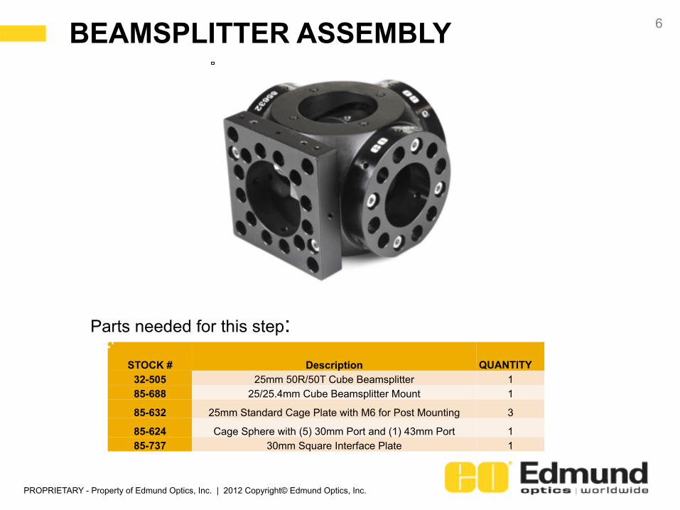
STOCK # Description
QUANTITY 32-505 25mm 50R/50T Cube Beamsplitter 1 85-688 25/25.4mm Cube Beamsplitter Mount 1
85-632 25mm Standard Cage Plate with M6 for Post Mounting 3
85-624 Cage Sphere with (5) 30mm Port and (1) 43mm Port 1 85-737 30mm Square Interface Plate 1
Parts needed for this step:
PROPRIETARY - Property of Edmund Optics, Inc. | 2012 Copyright© Edmund Optics, Inc.
BEAMSPLITTER ASSEMBLY 7
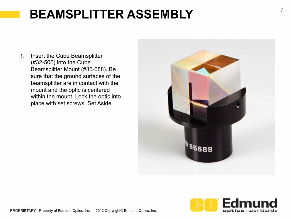
1. Insert the Cube Beamsplitter (#32-505) into the Cube Beamsplitter Mount (#85-688). Be sure that the ground surfaces of the beamsplitter are in contact with the mount and the optic is centered within the mount. Lock the optic into place with set screws. Set Aside.

PROPRIETARY - Property of Edmund Optics, Inc. | 2012 Copyright© Edmund Optics, Inc.
BEAMSPLITTER ASSEMBLY 8
2. Attach three 25mm Cage Mounting Plates (#85-632) onto the faces of the Sphere (#85-624) with M3 SHCS. Keep the three plates in the same plane as the large 43mm port on the cube and orient the plates so if the 43mm port is facing you, the M6 tapped holes are all pointing downwards (as shown).
3. Carefully insert the beamsplitter assembly (mount first) from Step 1 into the sphere through the 43mm port. Slide the base of the beamsplitter mount into the 25mm aperture of the cage plate from step 2. Use M3 set screws to lock the beamsplitter in place (alignment will be done later).
4. Attach the Square Interface Plate (#85-737) onto the 43mm port with M3 SHCS.

PROPRIETARY - Property of Edmund Optics, Inc. | 2012 Copyright© Edmund Optics, Inc.
2. IMAGE ARM
9

PROPRIETARY - Property of Edmund Optics, Inc. | 2012 Copyright© Edmund Optics, Inc.
IMAGE ARM 10
STOCK # Description
QUANTITY
85-624 Cage Sphere with (5) 30mm Port and (1) 43mm Port 1 85-737 30mm Square Interface Plate 1
85-488 Cage Support Rod 6mm Diameter x 100mm Length, M3 4
47-911 PCV Lens, 25mm Diameter x -25 FL, VIS 0 Coating 1
85-587 30mm Cage 25/25.4mm Diameter Lens Mount 1
85-630 30mm Standard Cage Plate with M6 for Post Mounting 1
Parts needed for this step:

PROPRIETARY - Property of Edmund Optics, Inc. | 2012 Copyright© Edmund Optics, Inc.
IMAGE ARM 11
5. Insert four of the 100mm rods (#85-488) into the 25mm Standard Cage Mounting Plate on the face opposite the 2” Square Mounting Bracket, and secure with M3 set screws.
6. Mount the 25mm diameter PCV lens (#47-911) inside the 25mm Lens Mount (#85-587) and secure with retaining ring.
7. Mount the assembly from step 6 inside the 30mm Cage Mounting Plate (#85-630). Secure with M3 set screws.
8. Slide the assembly from Step 7 onto the rods from Step 5 keeping the plate flush with the ends of the rods. Secure with M3 set screws.

PROPRIETARY - Property of Edmund Optics, Inc. | 2012 Copyright© Edmund Optics, Inc.
3. LASER ARM
12
PROPRIETARY - Property of Edmund Optics, Inc. | 2012 Copyright© Edmund Optics, Inc.
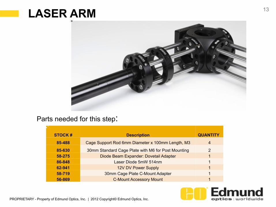
LASER ARM 13
STOCK # Description
QUANTITY
85-488 Cage Support Rod 6mm Diameter x 100mm Length, M3 4
85-630 30mm Standard Cage Plate with M6 for Post Mounting 2 58-275 Diode Beam Expander: Dovetail Adapter 1 86-848 Laser Diode 5mW 514nm 1 62-941 12V DV Power Supply 1 58-719 30mm Cage Plate C-Mount Adapter 1 56-869 C-Mount Accessory Mount 1
Parts needed for this step:
PROPRIETARY - Property of Edmund Optics, Inc. | 2012 Copyright© Edmund Optics, Inc.
LASER ARM 14
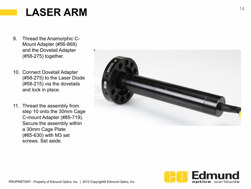
9. Thread the Anamorphic C-Mount Adapter (#56-869) and the Dovetail Adapter (#58-275) together.
10. Connect Dovetail Adapter (#58-275) to the Laser Diode (#58-215) via the dovetails and lock in place.
11. Thread the assembly from step 10 onto the 30mm Cage C-mount Adapter (#85-719). Secure the assembly within a 30mm Cage Plate (#85-630) with M3 set screws. Set aside.
PROPRIETARY - Property of Edmund Optics, Inc. | 2012 Copyright© Edmund Optics, Inc.
LASER ARM 15
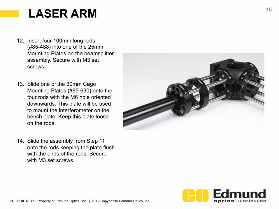
12. Insert four 100mm long rods (#85-488) into one of the 25mm Mounting Plates on the beamsplitter assembly. Secure with M3 set screws.
13. Slide one of the 30mm Cage Mounting Plates (#85-630) onto the four rods with the M6 hole oriented downwards. This plate will be used to mount the interferometer on the bench plate. Keep this plate loose on the rods.
14. Slide the assembly from Step 11 onto the rods keeping the plate flush with the ends of the rods. Secure with M3 set screws.

PROPRIETARY - Property of Edmund Optics, Inc. | 2012 Copyright© Edmund Optics, Inc.
4. FIXED MIRROR ARM
16
PROPRIETARY - Property of Edmund Optics, Inc. | 2012 Copyright© Edmund Optics, Inc.
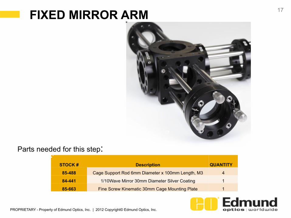
FIXED MIRROR ARM 17
STOCK # Description
QUANTITY
85-488 Cage Support Rod 6mm Diameter x 100mm Length, M3 4
84-441 1/10Wave Mirror 30mm Diameter Silver Coating 1
85-663 Fine Screw Kinematic 30mm Cage Mounting Plate 1
Parts needed for this step:
PROPRIETARY - Property of Edmund Optics, Inc. | 2012 Copyright© Edmund Optics, Inc.
FIXED MIRROR ARM 18
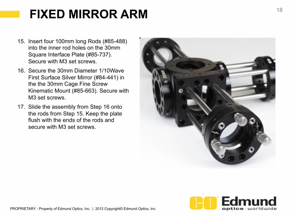
15. Insert four 100mm long Rods (#85-488) into the inner rod holes on the 30mm Square Interface Plate (#85-737). Secure with M3 set screws.
16. Secure the 30mm Diameter 1/10Wave First Surface Silver Mirror (#84-441) in the the 30mm Cage Fine Screw Kinematic Mount (#85-663). Secure with M3 set screws.
17. Slide the assembly from Step 16 onto the rods from Step 15. Keep the plate flush with the ends of the rods and secure with M3 set screws.

PROPRIETARY - Property of Edmund Optics, Inc. | 2012 Copyright© Edmund Optics, Inc.
5. TRANSLATION MIRROR ARM
19

PROPRIETARY - Property of Edmund Optics, Inc. | 2012 Copyright© Edmund Optics, Inc.
TRANSLATION MIRROR ARM 20
STOCK # Description
QUANTITY
85-632 25mm Standard Cage Plate with M6 for Post Mounting 1
85-488 Cage Support Rod 6mm Diameter x 100mm Length, M3 2
85-630 30mm Standard Cage Plate with M6 for Post Mounting 1
85-490 Cage Support Rod 6mm Diameter x 150mm Length, M3 2
47-973 ND:YAG Laser Line Mirror 25mm Dia. 532nm 0° 1 85-695 25.4mm Kinematic Mount 1 85-618 Micrometer Mount Kit 1 58-661 Micrometer Head Anvil 13mm 1
Parts needed for this step:
PROPRIETARY - Property of Edmund Optics, Inc. | 2012 Copyright© Edmund Optics, Inc.
TRANSLATION MIRROR ARM 21
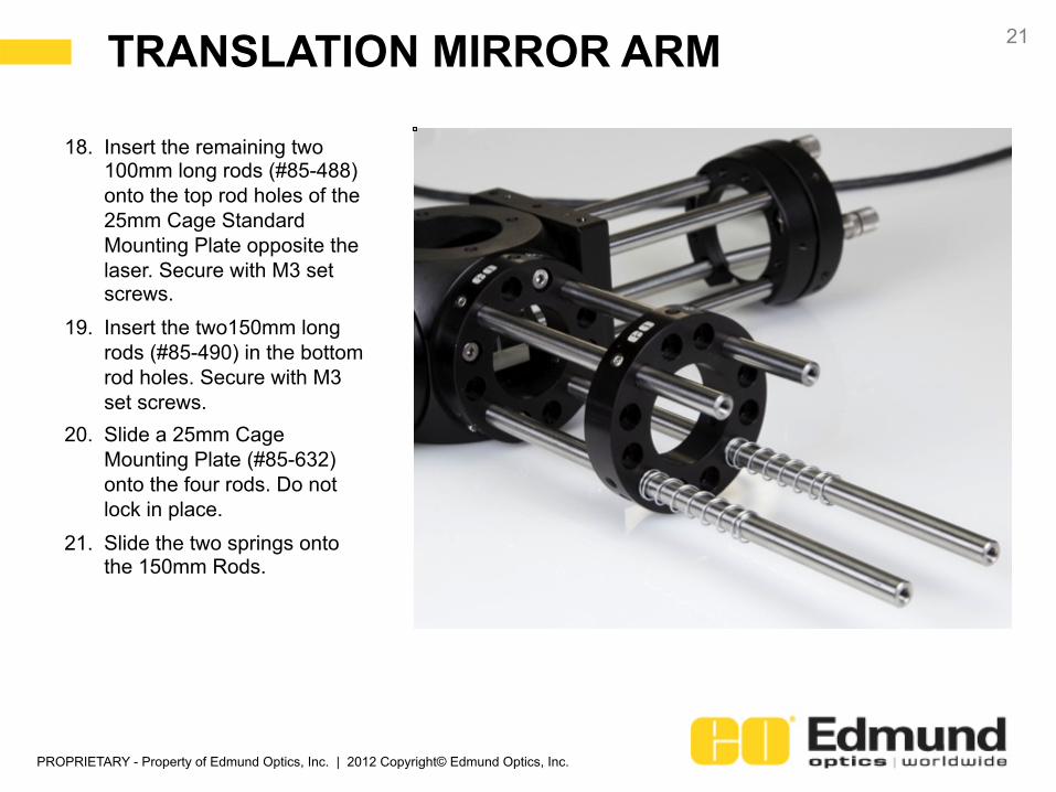
18. Insert the remaining two 100mm long rods (#85-488) onto the top rod holes of the 25mm Cage Standard Mounting Plate opposite the laser. Secure with M3 set screws.
19. Insert the two150mm long rods (#85-490) in the bottom rod holes. Secure with M3 set screws.
20. Slide a 25mm Cage Mounting Plate (#85-632) onto the four rods. Do not lock in place.
21. Slide the two springs onto the 150mm Rods.
PROPRIETARY - Property of Edmund Optics, Inc. | 2012 Copyright© Edmund Optics, Inc.
TRANSLATION MIRROR ARM 22
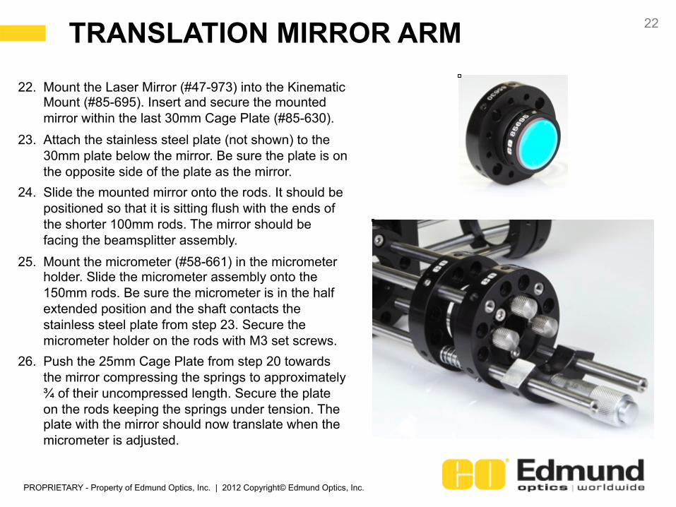
22. Mount the Laser Mirror (#47-973) into the Kinematic Mount (#85-695). Insert and secure the mounted mirror within the last 30mm Cage Plate (#85-630).
23. Attach the stainless steel plate (not shown) to the 30mm plate below the mirror. Be sure the plate is on the opposite side of the plate as the mirror.
24. Slide the mounted mirror onto the rods. It should be positioned so that it is sitting flush with the ends of the shorter 100mm rods. The mirror should be facing the beamsplitter assembly.
25. Mount the micrometer (#58-661) in the micrometer holder. Slide the micrometer assembly onto the 150mm rods. Be sure the micrometer is in the half extended position and the shaft contacts the stainless steel plate from step 23. Secure the micrometer holder on the rods with M3 set screws.
26. Push the 25mm Cage Plate from step 20 towards the mirror compressing the springs to approximately ¾ of their uncompressed length. Secure the plate on the rods keeping the springs under tension. The plate with the mirror should now translate when the micrometer is adjusted.

PROPRIETARY - Property of Edmund Optics, Inc. | 2012 Copyright© Edmund Optics, Inc.
MOUNTING AND ALIGNMENT
23
PROPRIETARY - Property of Edmund Optics, Inc. | 2012 Copyright© Edmund Optics, Inc.
MOUNTING 24
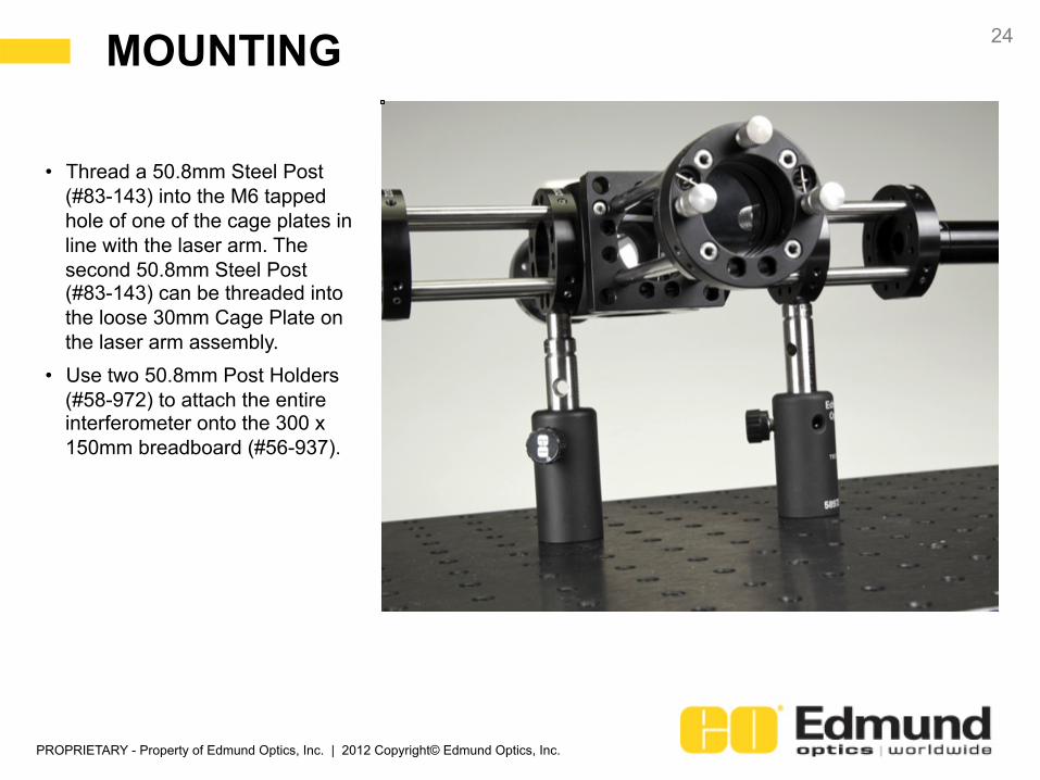
• Thread a 50.8mm Steel Post (#83-143) into the M6 tapped hole of one of the cage plates in line with the laser arm. The second 50.8mm Steel Post (#83-143) can be threaded into the loose 30mm Cage Plate on the laser arm assembly.
• Use two 50.8mm Post Holders (#58-972) to attach the entire interferometer onto the 300 x 150mm breadboard (#56-937).

PROPRIETARY - Property of Edmund Optics, Inc. | 2012 Copyright© Edmund Optics, Inc.
ALIGNMENT 25
Rough Alignment: 1. Use a micrometer to slide the position of the translation mirror so that it appears to have the same
distance to the beamsplitter as the other mirror. 2. Adjust the tip and tilt of the two mirrors until they appear to be perpendicular with the optical axis. 3. Remove the cage plate on the image arm that is holding the PCV lens. The lens should remain
within the cage plate. 4. Loosen the set screws holding the beamsplitter mount within the 25mm cage plate. Rotate the
beamsplitter until it is aligned such that half the beam from the laser will pass to the translation mirror and the other half will reflect to the fixed mirror. Keep the beamsplitter level.
Fine Alignment: 5. Turn off the laser. Place your eye where the PCV lens was and look into the beamsplitter. You
should see two reflections of your eye. Make slight adjustments to the beamsplitter holder until the two images of your eye overlap. Tightening the setscrews will change the positions of the eye images. The setscrews should be tightened slowly, ensuring the eye images are properly positioned, and that the setscrews are eventually fully secured.
6. While looking into the beamsplitter, use the tip-tilt stages to make final adjustments. The two reflections of your eye should be positioned so that they completely overlap. Once positioned, step back and turn the laser on. Interference fringes should now be visible. If not, make small adjustments to the micrometer. When aligned correctly, a bullseye pattern of fringes should be visible.
7. Slide the Cage Mount with the PCV lens back in place to enlarge the fringes making them more visible.

PROPRIETARY - Property of Edmund Optics, Inc. | 2012 Copyright© Edmund Optics, Inc.
START BUILDING NOW! 26
www.edmundoptics.com/cage-system
• Instructional Videos
• Application Examples
• 3D Models
• Demos
• and Much More