Embed Size (px)
Citation preview

STEP AP242 Format Expression and Development of MBD Model
FAN Shengting 1, YU Yong1,a) , DAI Sheng1, CAO Peng2 , ZHAO Gang 1,3
1School of Mechanics and Automation, Beihang University, Beijing 100191, China.
2 Institute of Telecommunication Satellite, China Academy of Space Technology, Beijing 100094, China 3 Key Laboratory of Aeronautics Smart Manufacturing, Ministry of Industry and Information Technology
Abstract: With the rapid development of modern manufacturing industry, Model Based Definition has been widely concerned in aerospace, and carried out in-depth promotion and application. A MBD information extraction method based on STEP AP242 is proposed to solve the problem that there are heterogeneous hardware and software in collaborative product development process and MBD model expression is not complete, not standardized, and not machine-readable. This paper takes the MBD model constructed by CATIA as research object, extracts the annotation and its association with the geometric information in MBD model using CATIA CAA(Component Application Architecture) secondary development technology, generates STEP standard neutral files according to STEP AP242 standard, and verifies the method using a structural model as an example at last.
Keywords: STEP AP242, MBD model, development
INTRODUCTION
With the rapid development of computer aided technology, modern manufacturing technology is developing to the direction of full-digital. Development mode of product has the trend of design in two-dimensional (2D) drawings and distribution in 2D drawings, design in three-dimensional (3D) models and distribution in 2D drawings, to design and distribution in full-3D models. Almost all of the computer-aided design (CAD) tools can generate product's MBD model, which is distributed to downstream and partner later. Computer-Aided Process Planning (CAPP), Computer Aided Manufacturing (CAM) , digital measuring machines and many other tools are adopted to assist manufacturing in the manufacturing process. These systems require not only the traditional geometric information, but also complete and machine-readable Geometric Dimension & Tolerance (GD&T) information[1]. However, the commercial software currently used in the MBD model containing GD&T information uses its own commercial format and has not yet been standardized to represent the MBD model. What’s more, the current represent is non-semantic which cannot be recognized by subsequent software systems and machine tools. So in the collaborative development process of product, human interaction is necessary in most cases, leading to the data transmission are not fluent and digital thread are not flowing in product development process. Based on this kind of demand, many scholars did a lot of work about GD&T information exchange. Tsai[2] developed a customized GD&T information model for constructing product GD&T data and application base on STEP standard ,before which the standardized STEP standard could only exchange geometry information. Ahmed F[3] and Barbau[4] used Web Ontology Language(OWL) to exchange the tolerance information. These studies worked based on customized model but not standard data models. After STEP AP242 was published, Venkiteswaran[5] transferred the Constrain Tolerance Graph(CTF) file into STEP AP242,which realizing the GD&T information exchange through STEP AP242. But it cannot meet the actual demand of existing project that the GD&T information is integrated in MBD model generated by commercial software, which is cannot be separated from MBD model.
A method is proposed in this paper to transfer the MBD model containing GD&T information into STEP AP242 neutral files, taking the MBD model constructed by CATIA as research object. The annotation and its association with the geometric information in MBD model are extracted by CAA, then standard neutral files is generated according to STEP AP242 standard ,and finally the method is verified by using a structural model as an example.
2nd International Conference on Materials Science, Machinery and Energy Engineering (MSMEE 2017)
Copyright © 2017, the Authors. Published by Atlantis Press. This is an open access article under the CC BY-NC license (http://creativecommons.org/licenses/by-nc/4.0/).
Advances in Engineering Research, volume 123
876

OVERVIEW OF STEP AP242
In 2009, a decision was made to merge AP203[6] and AP214[7] into one application protocol, and the
standard was published in 2014, called ISO 10303-242 “Managed Model Based 3D Engineering”[8]. The new standard incorporates old standards, reducing duplication of work and the costs of development and maintenance, and contains new features such as machine-readable manufacturing information. It is not only needed by GD&T information exchange among different CAD software, but also needed in manufacturing downstream, as the cornerstone of new smart manufacturing system[9]. STEP AP238 is the sub-standard in STEP-NC filed using the same general resources as other STEP standard. Therefore, implementation of STEP AP242 with semantic tolerance annotations also provides the basis for subsequent processing of STEP-NC.
STEP standard uses EXPRESS data-modelling language and introduces the concept of SCHEMA and ENTITY, in which relationship expressed in Subtype and Supertype. All of these are written in ASCII to .stp file (also called P21 file) defined by ISO 10303-21[10] to achieve the storage of information. STEP defines two ways of defining GD&T information[11]:
1) Presentation: this refers to conveyed information be converted to geometric elements (lines, arcs) by the source system in a way. The main purpose of Presentation is to facilitate human comprehension of the data. Presentation is supported by STEP AP203/AP214/AP242.
2) Representation: this refers to semantic representation of the GD&T information within appropriate STEP entities. The main purpose of Representation is to facilitate automated consumption of the data, for example, for later re-use or for downstream applications. Representation is supported only by STEP AP242.
At present, the STEP files constructed by mainstream commercial software adopt Presentation method, which is non-semantic and can’t be recognized by subsequent systems and machines. A CATIA structural model shown in Fig.1 is transferred into STEP file using Presentation method, and the result examined in STEP-NC Machine provided by STEP TOOLS Inc is shown in Fig.2. The Presentation of GD&T only displays the name of dimension and tolerance, and GD&T can’t be recognized and re-used by subsequent software systems and machine.
The result of GD&T information using Representation examined in STEP-NC Machine is shown in Fig.3. We can see that, Representation using the standardization STEP entities to achieve GD&T information machine-readable, which is one of the major differences between STEP AP242 and AP203/AP214. It can make CAPP or CAM system read the semantic dimension and tolerance to achieve the intelligent planning and optimization of the manufacturing process, and the GD&T information can also be directly compared with data from the digital measurement equipment and analyzed to achieve automatic tracking and controlling of the product quality[5].
FIGURE 1. A CATIA structural model
Advances in Engineering Research, volume 123
877
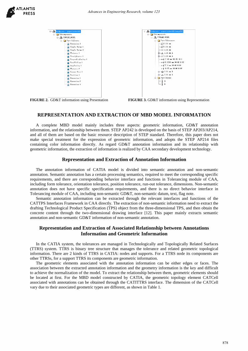
FIGURE 2. GD&T information using Presentation FIGURE 3. GD&T information using Representation
REPRESENTATION AND EXTRACTION OF MBD MODEL INFORMATION
A complete MBD model mainly includes three aspects: geometric information, GD&T annotation information, and the relationship between them. STEP AP242 is developed on the basis of STEP AP203/AP214, and all of them are based on the basic resource description of STEP standard. Therefore, this paper does not make special treatment for the expression of geometric information, and adopts the STEP AP214 files containing color information directly. As regard GD&T annotation information and its relationship with geometric information, the extraction of information is realized by CAA secondary development technology.
Representation and Extraction of Annotation Information
The annotation information of CATIA model is divided into semantic annotation and non-semantic annotation. Semantic annotation has a certain processing semantics, required to meet the corresponding specific requirements, and there are corresponding behavior interface and functions in Tolerancing module of CAA, including form tolerance, orientation tolerance, position tolerance, run-out tolerance, dimensions. Non-semantic annotation does not have specific specification requirements, and there is no direct behavior interface in Tolerancing module of CAA, including non-semantic GD&T, non-semantic datum, text, flag note.
Semantic annotation information can be extracted through the relevant interfaces and functions of the CATTPS Interfaces Framework in CAA directly. The extraction of non-semantic information need to extract the drafting Technological Product Specification (TPS) object from the three-dimensional TPS, and then obtain the concrete content through the two-dimensional drawing interface [12]. This paper mainly extracts semantic annotation and non-semantic GD&T information of non-semantic annotation.
Representation and Extraction of Associated Relationship between Annotations Information and Geometric Information
In the CATIA system, the tolerances are managed in Technologically and Topologically Related Surfaces (TTRS) system. TTRS is binary tree structure that manages the tolerance and related geometric topological information. There are 2 kinds of TTRS in CATIA: nodes and supports. For a TTRS node its components are other TTRSs, for a support TTRS its components are geometric information.
The geometric elements associated with the annotation information can be either edges or faces. The association between the extracted annotation information and the geometry information is the key and difficult to achieve the normalization of the model. To extract the relationship between them, geometric elements should be located at first. For the MBD model constructed by CATIA, the geometric topology element CATCell associated with annotations can be obtained through the CATITTRS interface. The dimension of the CATCell vary due to their associated geometric types are different, as shown in Table 1.
Advances in Engineering Research, volume 123
878

TABLE 1. Cell Type of CATCell Space Dimension Cell Type Associated geometry
0 Vertex Point 1 Edge Curve 2 Face Surface 3 Volume 3D Space
By determining the dimension of the CATCell, it is possible to determine whether the associated geometric
type is an edge or a face. According to the different types of geometric elements, an edge or a face, we take different approaches:
1) If the associated geometry is a face: B-rep of the face instantiated and then colored by the CATIVisProperties interface. The color information in CATIA has more than 16 million colors, and one color corresponds one face. We demine the face by specific color in STEP file later.
2) If the associated geometry is an edge: the classification for the curve of CATIA and STEP for is different, therefore we cannot directly extract the line definition parameters to determine the corresponding edge. In this paper, the start point ,the end point and the faces beside the edge are extracted to determine the edge. The method of determining the surface whether forms the edge is traversing all three-dimensional CATCells, checking whether the two-dimensional CATCell is the boarder of three-dimensional CATCell, and then using the method described in 1 )to color the surface.
According to the process mentioned above, the relationship between annotation information and geometric information is extracted and stored in XML format, which provide the basis for the follow-up STEP expression of MBD model. Two typical GD&T, non-sematic dimension and perpendicularity tolerance are extracted to XML files as shown in Fig.4.
FIGURE 4. XML of Two Typical Tolerance
REPRESENTATION AND IMPLEMENTATION OF MBD MODEL IN STEP
The STEP standard uses the ENTITY model to store and express the contained data information, and the geometric and non-geometric information should be mapped to the ENTITY model so that the information could be express through the STEP standard. In order to achieve the expression of semantic tolerance information machine-readable, the STEP entities should be generated using the Representation method.
Tolerance is divided into dimensional tolerance and geometric tolerance. In STEP AP242, the geometric tolerance information has two types depending on whether have reference elements[13].
Extracting Non-sematic Dimension
Extracting Perpendicularity Tolerance
Advances in Engineering Research, volume 123
879

1) Self-referenced tolerance, without the datum, using the geometric_tolerance entity; 2) Cross-referenced tolerance, with the datum, using geometric_tolerance_with_datum_ references entity. For example, flatness tolerance is a self-reference tolerance using the flatness_tolerance entity, as its
EXPRESS model is shown in Fig.5, inheriting the properties of its supertype geometric_tolerance. When generating the entity, it only need to associate the geometric geometry of the attached geomeric_tolerance_target without reference, and it achieves sematic presentation finally through the P21 file as shown in Fig. 6.
FIGURE 5. Express Model of flatness _tolerance and its Supertype geometric_tolerance
FIGURE 6. Flatness tolerance Instantiation
The method of representation of MBD information in STEP is shown in Fig. 7. 1) Read XML file and geometry STEP AP214 file, construct the tolerance entity according to tolerance type. 2) Find the associated geometric elements by color, associate it to tolerance entity and complete the
generation of the STEP AP242 file.
Read XML FileGet Type of Tolerance
Get Tolerance Information
Generate Tolerance Entity
Find Face by Color
Find Edge by Points and Faces
Attach the geometric element to Entities
FIGURE 7. Flow Chart for generating STEP files
APPLICATION AND VERIFICATION
According to the method proposed in this paper, a structural model shown in Fig.1 is taken as example to verify, as shown in Fig.9.The generated STEP AP242 file is analyzed and verified using STEP File Analyzer published by the National Institute of Standards and Technology (NIST) and STEP-NC Machine tools respectively. The result of STEP File Analyzer is listed in Table 2. It can be seen that the generated STEP AP242 file transferred from CATIA MBD model not only contains traditional geometric information, but also contains correct GD&T information, and the information is semantic to be recognized by other software and tools.
Advances in Engineering Research, volume 123
880

FIGURE 9. The Verification by a Structural Model
TABLE 2. The Result of STEP AP242 analyzed by STEP File Analyzer angularity_tolerance ∠ 1
flatness_tolerance ▱ 2 parallelism_tolerance ∕∕ 1
perpendicularity_tolerance ⏊ 1 position_tolerance ⊕ 1
straightness_tolerance - 1 dimensional location (5.1.1) 4
CONCLUSION
Considering the existing MBD model has not yet formed a standardized expression, and the dimension and tolerance information is non-semantic, which cannot be recognized by software system and machine, this paper describes the representation and extraction of MBD information based on CAA secondary development technology, the representation and implement of GD&T information in STEP AP242 and finally verifies the method using a structural model as an example. This method realizes the complete expression of MBD model information, achieves the conversion of human-read mode to machine-read mode. It provides the technical foundation for realizing the digital thread in the process of product development and the new generation intelligent manufacturing system.
ACKNOWLEDGMENTS
This paper is sponsored by the 2016 Special Scientific Research on Civil Aircraft Project of Ministry of Industry and Information Technology.
REFERENCES
1. Fischer K, Rosche P, Trainer A. Investigating the impact of standards-based interoperability for design to manufacturing and quality in the supply chain. National Institute of Standards and Technology, Report No. NISTGCR, 2015: 15-1009.
Advances in Engineering Research, volume 123
881

2. Tsai J C, Chuang T C, Guo D N. Development of a step-based dimensioning and tolerancing data model. PROCEEDINGS-NATIONAL SCIENCE COUNCIL REPUBLIC OF CHINA PART A PHYSICAL SCIENCE AND ENGINEERING, 1998, 22: 831-840.
3. Ahmed F, Han S. Interoperability of product and manufacturing information using ontology. Concurrent Engineering, 2015, 23(3): 265-278.
4. Barbau R, Krima S, Rachuri S, et al. OntoSTEP: Enriching product model data using ontologies. Computer-Aided Design, 2012, 44(6): 575-590.
5. Venkiteswaran A, Hejazi S M, Biswas D, et al. Semantic Interoperability of GD&T Data Through ISO 10303 Step AP242.ASME 2016 International Design Engineering Technical Conferences and Computers and Information in Engineering Conference. American Society of Mechanical Engineers, 2016: V02BT03A018-V02BT03A018
6. International Standards Organization, 2011, "Industrial automation systems and integration -- Product data representation and exchange -- Part 203: Application protocol: Configuration controlled 3D design of mechanical parts and assemblies," ISO/TC 184/SC 4.
7. International Standards Organization, 2010 ,"Industrial automation systems and integration -- Product data representation and exchange -- Part 214: Application protocol: Core data for automotive mechanical design processes, "ISO/TC 184/SC 4.
8. International Standards Organization, 2014, "Industrial automation systems and integration -- Product data representation and exchange -- Part 242: Application protocol: Managed model-based 3D engineering," ISO/TC 184/SC 4
9. Feeney A B, Frechette S P, Srinivasan V. A portrait of an ISO STEP tolerancing standard as an enabler of smart manufacturing systems . Journal of Computing and Information Science in Engineering, 2015, 15(2): 021001.
10. International Standards Organization, 2014, “Industrial automation systems and integration — product data representation and exchange — part 21: Implementation methods: Clear text encoding of the exchange structure” ISO/TC 184/SC 4
11. CAx-IF Recommended Practices for the Representation and Presentation of Product Manufacturing Information (PMI) (AP242) , Version 4.0, October 13,2014, https://www.cax-if.org/documents/rec_pracs_pmi_v40.pdf
12. TM Xu, ZN Chen, XJ Li. Extraction and implement of B-rep information facing to process planning system of three-dimensional machining. Computer system application,2014, 23(6):211-214(in Chinese).
13. Tsai J C. A STEP Translator toward Computer Integrated Tolerancing.Geometric Product Specification and Verification: Integration of Functionality. Springer Netherlands, 2003: 311-320.
Advances in Engineering Research, volume 123
882