Embed Size (px)
Citation preview

MAINTENANCE MANUAL
STEMME TSA-M
MAINTENANCE MANUAL
STEMME TSA-M
CHAPTER 27
FLIGHT CONTROLS

MAINTENANCE MANUAL
STEMME TSA-M
MAINTENANCE MANUAL
STEMME TSA-M
Page 0127 - TOC
TABLE OF CONTENTS
ChapterSection
Title Subject Page
FLIGHT CONTROLS - GENERAL .................................................................27-00-00 01Introduction 27-00-00 01General Description 27-00-00 01
AILERON CONTROL SYSTEM - DESCRIPTION.......................................27-10-00 01Introduction 27-10-00 01Description and Operation 27-10-00 01
RUDDER CONTROL SYSTEM - DESCRIPTION........................................27-20-00 01Introduction 27-20-00 01Description and Operation 27-20-00 01
ELEVATOR CONTROL SYSTEM - DESCRIPTION ....................................27-30-00 01Introduction 27-30-00 01Description and Operation 27-30-00 01
ELECTRICAL ELEVATOR TRIM CONTROL - DESCRIPTION................27-31-00 01Introduction 27-31-00 01Description and Operation 27-31-00 01
ELECTRICAL ELEVATOR TRIM CONTROL - TROUBLESHOOTING..27-31-00 101General 27-31-00 101Trobleshooting 27-31-00 101
ELECTRICAL ELEVATOR TRIM CONTROL - MAINTENANCEPRACTICES ........................................................................................................27-31-00 201
General 27-31-00 201Indicator Removal/Installation 27-31-00 201Control Relay Unit Removal/Installation 27-31-00 201Actuator Removal/Installation 27-31-00 201Inspection/Checks 27-31-00 202
FLAP CONTROL SYSTEM - DESCRIPTION ...............................................27-50-00 01Introduction 27-50-00 01Description and Operation 27-50-00 01
AIRBRAKE CONTROL SYSTEM - DESCRIPTION .....................................27-60-00 01Introduction 27-60-00 01Description and Operation 27-60-00 01
Nov 18/11

MAINTENANCE MANUAL
STEMME TSA-M
MAINTENANCE MANUAL
STEMME TSA-M
FLIGHT CONTROLS - GENERAL
1. Introduction
A. This chapter contains information about flight controls used to manually control the aircraft in flight. It includes the functioning and maintenance aspects of the systems.
2. General Description
A. The conventionally designed flight control system of the S6 is divided into the aileron control, the rudder control, elevator control, air brakes control and the wing flaps system. The aircraft is equipped with dual controls.The control stick, the rudder pedals, the wing flap and air brakes control levers are used for control input. An elevator trim can be actuated electrically. Aileron and elevator control motion is transferred to control surfaces through push-pull rods and bell cranks. The rudder control system utilizes control cables and bell cranks for rudder actuation. The wing flaps and air brakes control systems also primarily consist of a linkage of push-pull rods and bell cranks. The flap control system features a flap-aileron mixing system.
B. For dimensions, areas and free play tolerances of the control surfaces refer to Chapter 6 "Dimensions and Areas“ of this manual.
27-00-00Page 01
Nov 18/11

MAINTENANCE MANUAL
STEMME TSA-M
MAINTENANCE MANUAL
STEMME TSA-M
AILERON CONTROL SYSTEM - DESCRIPTION
1. Introduction
A. This section describes that portion of the flight control system, which controls the position and movement of the ailerons.
2. Description and Operation
A. The aileron control system uses several push-pull rods and bell cranks to actuate two separated control surfaces at each outer wing portion. The L/H ailerons deflect differentiated in relation to the R/H ailerons. Additional the outer ailerons deflect more than the inner ones. The aileron control has an interconnect to the wing flap system. Thus the wing flap control motion is transferred in a defined percentage also to the ailerons.
B. For aileron control system design and function refer to Figure 1.
27-10-00Page 01
Nov 18/11

MAINTENANCE MANUAL
STEMME TSA-M
MAINTENANCE MANUAL
STEMME TSA-M
Aileron Control System Design and FunctionFigure 01
27-10-00Page 02
27-20-00Page 01
RUDDER CONTROL SYSTEM - DESCRIPTION
1. Introduction
A. This section describes that portion of the flight control system, which controls the position and movement of the rudder.
2. Description and Operation
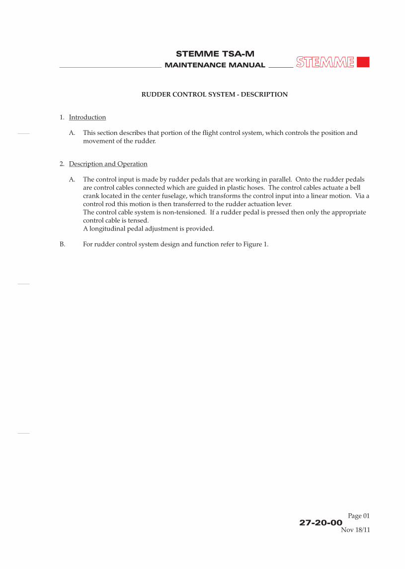
A. The control input is made by rudder pedals that are working in parallel. Onto the rudder pedals are control cables connected which are guided in plastic hoses. The control cables actuate a bell crank located in the center fuselage, which transforms the control input into a linear motion. Via a control rod this motion is then transferred to the rudder actuation lever.The control cable system is non-tensioned. If a rudder pedal is pressed then only the appropriate control cable is tensed.A longitudinal pedal adjustment is provided.
B. For rudder control system design and function refer to Figure 1.
Note:Only R/H portion of system shown. L/H one is identical.
Function schematic shows only the L/H inner control surface. The outer control surface functions analogical.
Interconnect to the Wing Flap System
Nov 18/11Nov 18/11
MAINTENANCE MANUAL
STEMME TSA-M
MAINTENANCE MANUAL
STEMME TSA-M
Aileron Control System Design and FunctionFigure 01
27-10-00Page 02
27-20-00Page 01
RUDDER CONTROL SYSTEM - DESCRIPTION
1. Introduction
A. This section describes that portion of the flight control system, which controls the position and movement of the rudder.
2. Description and Operation
A. The control input is made by rudder pedals that are working in parallel. Onto the rudder pedals are control cables connected which are guided in plastic hoses. The control cables actuate a bell crank located in the center fuselage, which transforms the control input into a linear motion. Via a control rod this motion is then transferred to the rudder actuation lever.The control cable system is non-tensioned. If a rudder pedal is pressed then only the appropriate control cable is tensed.A longitudinal pedal adjustment is provided.
B. For rudder control system design and function refer to Figure 1.
Note:Only R/H portion of system shown. L/H one is identical.
Function schematic shows only the L/H inner control surface. The outer control surface functions analogical.
Interconnect to the Wing Flap System
Nov 18/11Nov 18/11

MAINTENANCE MANUAL
STEMME TSA-M
MAINTENANCE MANUAL
STEMME TSA-M
ELEVATOR CONTROL SYSTEM - DESCRIPTION
1. Introduction
A. This section describes that portion of the flight control system, which controls the position and movement of the elevator including the elevator trim system.
2. Description and Operation
A. Both control sticks are coupled by a connection tube. A bell crank at the connection tube converts the rotary into a linear control motion. Then, the control movements are transmitted via push-pull rods to the end of the tail boom and then straight up to the elevator fitting. In the tail boom, the push-pull rod is supported by linear motion ball bearings. Adjustable stops for the longitudinal control are installed in the middle of the connection tube.
The elevator control system features an electrical actuated spring trim system. The trim system is coupled to the elevator system bell crank in the FWD tail boom and influences so the elevator control system as desired by the pilot.
B. For aileron control system design and function refer to Figure 1.
27-30-00Page 01
Rudder Control System Design and FunctionFigure 01
27-20-00Page 02
ADetail-
A
Pedals
S-Hoses
Rudder PedalsAdjustment Lever
Nov 18/11Nov 18/11

MAINTENANCE MANUAL
STEMME TSA-M
MAINTENANCE MANUAL
STEMME TSA-M
Elevator Control System Design and FunctionFigure 01
Trim System (Ref. 27-31-00)
Connecting Tube
27-30-00Page 02
ELECTRICAL ELEVATOR TRIM CONTROL - DESCRIPTION
1. Introduction
A. This section describes the actuation and control of the electrical elevator trim system.
2. Description and Operation
A. The electrical trim system consists of an electrical jackscrew actuator inside the fwd tail boom, two push buttons on the sticks, a control relay unit and an indicator at the instrument panel. The electrical elevator trim is powered by the main bus via a circuit breaker at the instrument panel.
B. When the push button on the stick is moved forwards or backwards, the control relay unit activates the actuator to move in the related direction. The actuator moves the elevator pushrod via springs in the position desired by the pilot. The actuator includes internal limit switches and will stop automatically at the end of travel.
C. The actuator includes an electric potentiometer. The potentiometer is connected to a position indicator at the instrument panel, which shows the actual position of the actuator by green LED.
27-31-00Page 01
Nov 18/11Nov 18/11

MAINTENANCE MANUAL
STEMME TSA-M
MAINTENANCE MANUAL
STEMME TSA-M
27-31-00Page 101
ELECTRICAL ELEVATOR TRIM CONTROL
1. General
A. This section lists some of the more common troubles, which may be encountered in maintaining the electrical elevator trim control system, their probable causes and remedies
B. If a problem on the electrical elevator trim control system occurs, at first check all electrical connections and wiring for proper conditions.
2. Troubleshooting
A. Refer to wiring diagram P308-051.162.
- TROUBLESHOOTING
Trouble Probable Cause Remedy
Actuator don’t move No power supply at trim system Check battery switch and circuit breaker
Verify that all electrical connections are connected and in proper condition
No signal from push buttons on stick to control relay
Check wiring for interruptions
Disconnect plugs S1 and / or S2 and check push buttons for function
Control relay unit defective Replace control relay unit
Actuator don’t stop automatically at the end of travel
Limit switch inside actuator defective Replace actuator
No indication of trim position No signals from potentiometer to indicator
Check wiring and connectors for proper condition
Indicator defective Replace indicator
Actuator moves in wrong direction and/or indicator shows wrong moving direction
Reversed polarities of the connectors of push buttons on stick or actuator or indicator
Check wiring for accordance to wiring diagram
Nov 18/11

MAINTENANCE MANUAL
STEMME TSA-M
MAINTENANCE MANUAL
STEMME TSA-M
27-31-00Page 201
ELECTRICAL ELEVATOR TRIM CONTROL
1. General
A. The maintenance practices are limited to functional checks of the system and removal/installation of components.
2. Indicator Removal/Installation
A. Remove Indicator(1) Remove instrument panel cover.(2) Disconnect indicator.(3) Unscrew indicator from instrument panel and remove from panel.
B. Install Indicator(1) Install indicator in reversed sequence to removal.(2) Install instrument panel cover.
3. Control Relay Unit Removal/Installation
A. Remove Control Relay Unit(1) Remove instrument panel cover.(2) Disconnect control relay unit.(3) Remove control relay unit from rack.
B. Install Control Relay Unit(1) Install control relay unit in reversed sequence to removal.(2) Install instrument panel cover.
4. Actuator Removal/Installation
A. Remove Actuator(1) Remove upper, right hand and left hand side engine cowling (refer to 71-10-00).(2) Disconnect plug of actuator.(3) Detach the actuator from elevator control elements.(4) Remove actuator from aircraft.
B. Install Actuator(1) Install actuator in reversed sequence to removal.(2) Install engine cowlings (refer to 71-10-00).
- MAINTENANCE PRACTICES
Nov 18/11

MAINTENANCE MANUAL
STEMME TSA-M
MAINTENANCE MANUAL
STEMME TSA-M
FLAP CONTROL SYSTEM - DESCRIPTION
1. Introduction
A. This section describes that portion of the flight control system, which controls the position and movement of the flaps.
2. Description and Operation
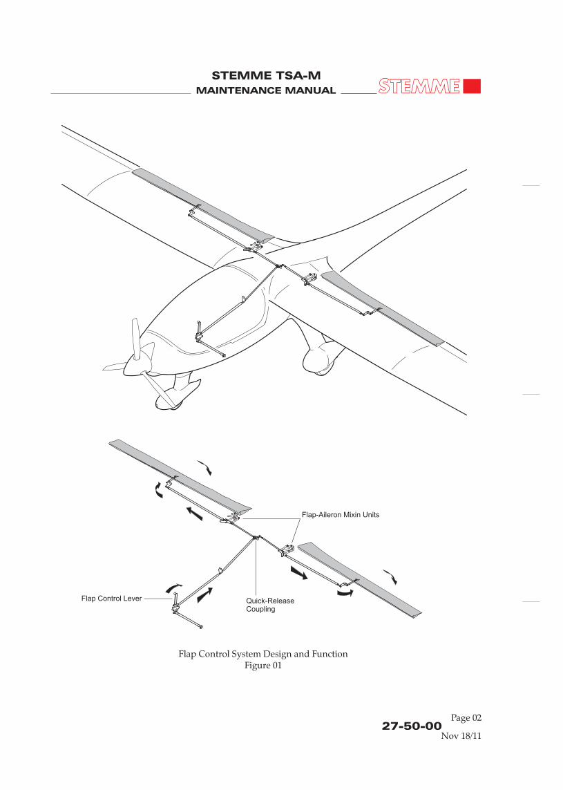
A. The wing flaps system consists of the wing flap control lever in the cockpit, several push-pull rods, bell cranks and the control surfaces at the trailing edge of the L/H and R/H inner wing portion.
The wing flap control has an interconnect to the aileron control system. Due to this flap-aileron mixing feature the wing flap control motion is transferred in a defined percentage also to the ailerons. The aileron control input has no effect to the wing flap system.
The wing flaps are fixed in the desired position by means of the flap control lever: Adjacent to the control lever basis a metal plate is mounted that has appropriate to the selectable flap positions arranged holes. A stud at the control lever basis is engaged spring loaded in one of this holes and holds so the lever in the desired position. To select another position the lever must be pushed rightwards to disengage the lever stud from hole and then moved into another hole.The selectable positions are CRUISE, NEUTRAL, TAKEOFF-LANDING1 (TO/LDG 1) and LANDING 2 (LDG 2).
B. For an illustration of flap control system design and function refer to Figure 1.
27-50-00Page 01
5. Inspection/Checks
A. Refer to Scheduled Maintenance Checks (refer to 05-20-00).
Perform functional check by pushing the trim buttons on the stick to “nose heavy” and “tail heavy” and observe the movement of the sticks and the indicator for proper function, correct directions of movement.
27-31-00Page 202
Nov 18/11Nov 18/11

MAINTENANCE MANUAL
STEMME TSA-M
MAINTENANCE MANUAL
STEMME TSA-M
FLAP CONTROL SYSTEM - DESCRIPTION
1. Introduction
A. This section describes that portion of the flight control system, which controls the position and movement of the flaps.
2. Description and Operation
A. The wing flaps system consists of the wing flap control lever in the cockpit, several push-pull rods, bell cranks and the control surfaces at the trailing edge of the L/H and R/H inner wing portion.
The wing flap control has an interconnect to the aileron control system. Due to this flap-aileron mixing feature the wing flap control motion is transferred in a defined percentage also to the ailerons. The aileron control input has no effect to the wing flap system.
The wing flaps are fixed in the desired position by means of the flap control lever: Adjacent to the control lever basis a metal plate is mounted that has appropriate to the selectable flap positions arranged holes. A stud at the control lever basis is engaged spring loaded in one of this holes and holds so the lever in the desired position. To select another position the lever must be pushed rightwards to disengage the lever stud from hole and then moved into another hole.The selectable positions are CRUISE, NEUTRAL, TAKEOFF-LANDING1 (TO/LDG 1) and LANDING 2 (LDG 2).
B. For an illustration of flap control system design and function refer to Figure 1.
27-50-00Page 01
5. Inspection/Checks
A. Refer to Scheduled Maintenance Checks (refer to 05-20-00).
Perform functional check by pushing the trim buttons on the stick to “nose heavy” and “tail heavy” and observe the movement of the sticks and the indicator for proper function, correct directions of movement.
27-31-00Page 202
Nov 18/11Nov 18/11
MAINTENANCE MANUAL
STEMME TSA-M
MAINTENANCE MANUAL
STEMME TSA-M
Flap Control System Design and FunctionFigure 01
Flap Control Lever
Flap-Aileron Mixin Units
Quick-Release Coupling
27-50-00Page 02
AIR-BRAKE CONTROL SYSTEM - DESCRIPTION
1. Introduction
A. This section describes that portion of the flight control system, which controls the position and movement of the air-brakes.
2. Description and Operation
A. The aircraft is equipped with two-storey Schempp-Hirth style air-brakes.
The air-brake system consists of the air-brake pilot's and co-pilot's blue control levers in the cockpit, several push-pull rods, bell cranks and the control surfaces in the inner section of the L/H and R/H outer wings.
The air-brake control levers are coupled by means of a connection tube. Travel of the levers is transmitted via push-pull rods and bell cranks to a driving lever that rotates in the center fuselage. This lever sets the push-pull rods in each wing in a linear motion. The rods are connected to a bell crank which is located in each outer wing root. The bell crank actuates a linkage which is driving two rotational shafts in each air-brake box which extends the air-brakes. The push-pull rods are connected to the bell crank in each outer wing root by quick-release couplings and are supported by linear motion ball bearings.
The air-brakes are locked in the retracted position by an air-brake lock at the wing joints. The locked position as well as the fully extended position can be adjusted.
B. For an illustration of air-brake control system design and function refer to Figure 1.
27-60-00Page 01
Nov 18/11Nov 18/11

MAINTENANCE MANUAL
STEMME TSA-M
MAINTENANCE MANUAL
STEMME TSA-M
CHAPTER 28
FUEL
Quick-Release Coupling
Quick-Release Coupling
Control Lever
27-60-00Page 02
Air-Brake Control System Design and FunctionFigure 01
Note:Function schematic shows only the L/H control system portion. The R/H one functions analogical.
Nov 18/11

MAINTENANCE MANUAL
STEMME TSA-M
MAINTENANCE MANUAL
STEMME TSA-M
Page 0128 - TOC
TABLE OF CONTENTS
ChapterSection
Title Subject Page Effectivity
FUEL - GENERAL .............................................................................................28-00-00 1Introduction 28-00-00 1General Description 28-00-00 1
FUEL DISTRIBUTION - DESCRIPTION.......................................................28-20-00 01Introduction 28-20-00 01Description and Operation 28-20-00 01
FUEL DISTRIBUTION - TROUBLESHOOTING.........................................28-20-00 101General 28-20-00 101Troubleshooting 28-20-00 101
FUEL DISTRIBUTION - MAINTENANCE PRACTICES.............................28-20-00 201Main and Auxiliary Feeder Pump Removal/Installation 28-20-00 201Circulation and/or Transfer Pump Removal/Installation 28-20-00 201Inspection/Checks 28-20-00 201Fuel Check Valves Replacement 28-20-00 202Fuel Hoses Replacement 28-20-00 202
FUEL INDICATION - DESCRIPTION ...........................................................28-40-00 01Introduction 28-40-00 01Description and Operation 28-40-00 01
FUEL INDICATION - TROUBLESHOOTING .............................................28-40-00 101General 28-40-00 101Troubleshooting 28-40-00 101
FUEL INDICATION - MAINTENANCE PRACTICES.................................28-40-00 201Fuel Level Indicator Removal/Installation 28-40-00 201Fuel Level Sender Removal/Installation 28-40-00 201Low Fuel Switch Removal/Installation 28-40-00 202Adjustment/Test 28-40-00 202
Nov 18/11

MAINTENANCE MANUAL
STEMME TSA-M
MAINTENANCE MANUAL
STEMME TSA-M
FUEL SYSTEM - GENERAL
1. Introduction
A. This chapter describes such systems and components, which store and deliver fuel to the engine.
2. General Description
A. The fuel system of the S6 (Refer to Fig. 01) consists of a main fuel tank which integrates a feeder compartment and a circulation pump installed in the right inner wing, several filters in the supply line, a main fuel pump, an auxiliary fuel pump and two single-barrel float type carburetors in the engine compartment as well as a fuel return line.Optionally, an additional integral tank can be installed in the left inner wing. The tank is designed as a completely external tank. The fuel of this tank is fed into the right wing tank by a transfer pump.
Fuel Quantity Data:
Fuel capacity, standard (R/H fuel tank): 1x 65 l 1x 17.2 US gal.Feeder compartment of the R/H fuel tank 8 l 2.1 US gal.Fuel capacity, optional (R/H + L/H fuel tank): 2x 65 l 2x 17.2 US gal.Unusable fuel, R/H: 2.1 l 0.55 US gal.Unusable fuel, L/H: 1 l 0.3 US gal.
B. Fuel Supply(1) The fuel is moved from the main compartment to the feeder compartment by a continuously
running circulation pump. If the feeder compartment is completely filled, then the fuel flows back to the main compartment through an opening in the divider.The feeder compartment supplies the engine with fuel. A coarse filter and fine filter are integrated into the supply line to the engine.Both, the supply and the return line are connected with the fuel system (which is installed in the fuselage) through quick connectors.The fuel flows from the quick connectors to the fuel pumps (main fuel pump and auxiliary fuel pump). From there, it continues to the fuel shut-off-valve in the cockpit and then to the pressure-regulator in front of the carburetors.Excess fuel flows through a return line from the pressure regulator back to the feeder compartment.
The fuel of the additional tank can be moved to the main tank by means of a transfer pump.The transfer of fuel is automatically regulated. The automatic regulator can be activated and de-activated by the pilot with the switch TRANSFER PUMP. The switch is located at the left lower instrument panel (Ref. 31-00-00). The transfer begins if the main tank is filled to less than 2/3 - 3/4 of its capacity or the feeder tank is filled below the reaction point of the low-fuel sensor. It ends once the amount of fuel in the main-tank has reached approx. 2/3 - 3/4 of its capacity again and the feeder tank is filled above the reaction point of the sensor.
28-00-00Page 01
Nov 18/11

MAINTENANCE MANUAL
STEMME TSA-M
MAINTENANCE MANUAL
STEMME TSA-M
(2) The fuel shut off valve is located on the rear center console near the head of the pilot. It separates the engine from the fuel supply (horizontal „OPEN“ and vertical „CLOSED“).
C. Fuel System IndicatingThe amount of fuel in each tank is measured with capacitive sensors. This data is then displayed on the instrument panel by on fuel level indicator for each installed tank.An additional optical sensor is mounted in the feeder compartment of the right wing tank. It signals, that less than approx. 1.3 - 1.9 US gal / 5 - 7 l of fuel remain in the feeder compartment.
The following indicators are installed on the instrument panel (Ref. also 31-00-00):(1) Low Fuel Caution Light (yellow)
Indicates remaining fuel less than 1.3 - 1.9 US gal / 5 - 7 l gal in feeder-compartment(2) Auxiliary Fuel Pump light (green)
Indicates a running auxiliary fuel pump(3) Fuel Level Indicator Right and Left (optional)
The indicator shows the amount of fuel in the appropriate fuel tanks.(4) Fuel Flow Indicator (optional)
The indicator shows the current fuel flow to the engine
D. Ventilation of the Fuel SystemThe fuel tanks are vented outboard through vent lines made from PVC, which protrude through the wing bottom surface at the wing joints between the inner wing and outer wings. Both fuel filler caps are also vented.
E. Fuel Drain SystemContaminated fuel (water, particles and similar) can be drained through the sumps of each compartment of the right tank. These drain valves are located at the bottom of the right wing (Ref. 06-30-00, 610AB and 610BB).
28-00-00Page 02
Fuel System SchematicFigure 01
28-00-00Page 03
Fuel Pressure
Engine Compartment
Pressure Regulatorsat Carburetors
Air Box
Air Box Pressure
Cockpit
Left Right
Red Fuel PressureWarning Light
Difference PressureSensor
yellow LOW FUELCaution LightFuel Shut-Off Valve
Green Indication Light
Aux. Fuel Pump
Schnelltrennstelle
Coarse Filter
Fine Filter
Fine Filter
Fine Filter
Main Fuel Pump
Aux. Fuel Pump
Rückschlagventil Check Valves
Transfer Pump if optional left aux.
tank is installed
Circulation Pump
Fuel Line
Electrical Line
Tankentlüftung Fuel Tank Vents
IIII IIII
left right
Fuel Level
Engine Bus Aux. PumpON
OFF
Transfer PumpControl
Transfer Pumo(opt. left aux. tank)
Quick-DisconnectFittings
Indicators
Fuel Flow Sender FWD
Fuel Flow Sender RTN
Nov 18/11Nov 18/11

MAINTENANCE MANUAL
STEMME TSA-M
MAINTENANCE MANUAL
STEMME TSA-M
FUEL DISTRIBUTION - DESCRIPTION
1. Introduction
A. This section describes that portion of the fuel system, which is used to distribute fuel from the storage system to the power plant.The system consists primarily of several fuel pumps, fuel lines, and controls.
2. Description and Operation
A. The system is supplied by the engine bus and consists of:
28-20-01 fuse main feeder pump TCU board
28-20-02 main feeder pump rear cockpit wall 28-20-03 circuit breaker switch aux. feeder pump instrument panel 28-20-04 auxilliary feeder pump rear cockpit wall
28-20-05 fuse circulation pump TCU board 28-20-06 circulation pump center wing spar 28-20-07 circuit breaker switch transfer pump instrument panel
28-20-08 transfer pump center wing spar 28-20-09 relay center wing spar 28-20-10 diode center wing spar
There are four electrical fuel pumps installed: The main feeder pump delivers the fuel from the feeder compartment to the fuel pressure regulator.The auxiliary feeder pump is installed as back-up to the main feeder pump.The circulation pump delivers fuel from the main compartment of the R/H wing tank into the feeder compartment.The transfer pump delivers fuel from the L/H wing tank (optional) into the feeder compartment. Thanks to the opening in the divider between the feeder compartment, the transfer pump will fill the main compartment when the feeder compartment is completely filled.The main and auxiliary fuel pumps are radial pumps and located on the L/H side of rear cockpit wall. The circulation and the transfer pumps are membrane pumps and fixed at bottom of the center wing spar.
B. FusesThe fuses of the main feeder pump and the circulation pump are located in a fuse holder on the TCU board. The position of the fuses is marked on the cover of the fuse holder.
Fuse RatingMain Feeder Pump 3 ampCirculation Pump 5 amp
The auxiliary feeder pump and the transfer pump are protected by their switches, which include circuit breaker function. (protector switches).
28-20-00Page 01
May 04/12

MAINTENANCE MANUAL
STEMME TSA-M
MAINTENANCE MANUAL
STEMME TSA-M
FUEL DISTRIBUTION - DESCRIPTION
1. Introduction
A. This section describes that portion of the fuel system, which is used to distribute fuel from the storage system to the power plant.The system consists primarily of several fuel pumps, fuel lines, and controls.
2. Description and Operation
A. The system is supplied by the engine bus and consists of:
28-20-01 fuse main feeder pump TCU board
28-20-02 main feeder pump rear cockpit wall 28-20-03 circuit breaker switch aux. feeder pump instrument panel 28-20-04 auxilliary feeder pump rear cockpit wall
28-20-05 fuse circulation pump TCU board 28-20-06 circulation pump center wing spar 28-20-07 circuit breaker switch transfer pump instrument panel
28-20-08 transfer pump center wing spar 28-20-09 relay center wing spar 28-20-10 diode center wing spar
There are four electrical fuel pumps installed: The main feeder pump delivers the fuel from the feeder compartment to the fuel pressure regulator.The auxiliary feeder pump is installed as back-up to the main feeder pump.The circulation pump delivers fuel from the main compartment of the R/H wing tank into the feeder compartment.The transfer pump delivers fuel from the L/H wing tank (optional) into the feeder compartment. Thanks to the opening in the divider between the feeder compartment, the transfer pump will fill the main compartment when the feeder compartment is completely filled.The main and auxiliary fuel pumps are radial pumps and located on the L/H side of rear cockpit wall. The circulation and the transfer pumps are membrane pumps and fixed at bottom of the center wing spar.
B. FusesThe fuses of the main feeder pump and the circulation pump are located in a fuse holder on the TCU board. The position of the fuses is marked on the cover of the fuse holder.
Fuse RatingMain Feeder Pump 3 ampCirculation Pump 5 amp
The auxiliary feeder pump and the transfer pump are protected by their switches, which include circuit breaker function. (protector switches).
28-20-00Page 01
May 04/12
MAINTENANCE MANUAL
STEMME TSA-M
MAINTENANCE MANUAL
STEMME TSA-M
C. OperationAll pumps are running at nominal 14V.The main pump is supplied from the internal generator bus and protected by a fuse at the TCU board. The pump is running as soon as the engine bus is activated by the switch ENG on the center lower instrument panel.The auxiliary pump is supplied from the engine bus. The pilot can activate the pump by the switch AUX PUMP at the left lower instrument panel. This rocker switch includes a circuit breaker function.The circulation pump is supplied from the internal generator bus and protected by a fuse at the TCU board. The pump is running as soon as the engine bus is activated by the switch ENG on the center lower instrument panel.The transfer pump is supplied from the engine bus. The pump is controlled automatically by the fuel capacity sender of the main fuel compartment and the low level switch of the feeder compartment of the R/H wing. The pilot can activate the pump by the switch TRANSFER PUMP at the left lower instrument panel. This rocker switch includes a circuit breaker function. The transfer starts to work if the main compartment fuel level is below 2/3 - 3/4 OR the feeder tank fuel level is below the reaction point of the low level switch. The transfer stops when the main compartment fuel level is more than 2/3 - 3/4 AND the feeder tank fuel level is above the reaction point of the low level switch.
FUEL DISTRIBUTION - TROUBLESHOOTING
1. General
A. This section lists some of the more common troubles, which may be encountered in maintaining fuel distribution system, their probable causes and remedies
B. References:(1) Chapter 24-00-00(2) Wiring diagram P308-150.00, P308-360.902(3) Component List P309-006.000
2. Troubleshooting
NOTES: Because the composite airframe not supply electrical ground to all electrical devices, it is important to check the negative power supply connection to a/c ground as well as the positive power supply.All voltages to be measured are nominal 14V power supply voltage, if not specified. Refer 24-00-00 for detailed power supply voltage range depending of mode of operation of the aircraft.
A. Main and Auxiliary Feeder PumpsIf the pump doesn't work, check electrical power supply, fuse, connectors and wires for proper condition. Measure the voltage directly at the screw connections at the pump. If the voltage is within the limits and the pump doesn't work, replace the pump. If the voltage at the connection is out of the limits, refer 24-00-00 for trouble shooting.
B. Circulation PumpIf the pump not works, check electrical power supply, fuse, connectors and wires for proper condition. Check that the internal generator bus is powered. Measure the voltage at the 2pole connector of the pump. If the voltage is within the limits and the pump doesn't work, replace the pump. If the voltage at the connection is out of the limits, refer 24-00-00 for trouble shooting.
C. Transfer PumpIf the pump not works, make sure that the conditions to activate the pump are fulfilled: low fuel levels in feeder or main fuel compartment of R/H wing. Then measure the voltage at the 2pole connector of the pump. If the voltage is within the limits and the pump doesn't work, replace the pump. If no positive voltage is present, check switch and wiring and connectors. If no ground connection is present, disconnect the 2pole plug of the low fuel switch of the feeder compartment. Short-circuit that plug at aircraft side to simulate a low fuel signal. If the pump works now, check the low fuel switch in accordance to 28-40-00. If the pump still not works, although a low fuel level is simulated, remove the spiral wrap from the wire bundle at the center wing spar. Identify, check, and if necessary replace the relay and/or diode.
28-20-00Page 02
28-20-00Page 101
Nov 18/11Nov 18/11

MAINTENANCE MANUAL
STEMME TSA-M
MAINTENANCE MANUAL
STEMME TSA-M
FUEL DISTRIBUTION - MAINTENANCE PRACTICES
1. Main and Auxiliary Feeder Pump Removal/Installation
A. Remove Main and/or Auxiliary Feeder Pump(1) Switch BATT off.(2) Place some cloth below the pump area to absorb potentially dripping fuel.(3) Disconnect the electrical wires from the connection screws.(4) Loosen the screw of the perforated metal ring around the pump.(5) Disconnect the fuel hoses from both sides of the pump.(6) Loosen the screw of the clamp that holds the pump.(7) Remove the pump from the clamp and remove the perforated metal ring from the pump.
B. Install Main and/or Auxiliary Feeder Pump(1) Attach the perforated metal ring to the pump.(2) Put the pump into the clamp and tighten the clamp screw and the screw of the perforated
metal ring.(3) Attach the fuel hoses to the pump.(4) Connect the electrical wires to the connection screws.
NOTE: Attend the polarity of electrical connection.
(5) Perform leak test after pump replacement.
2. Circulation and/or Transfer Pump Removal/Installation
A. Remove Circulation and/or Transfer Pump(1) Place some cloth below the pump area to absorb potentially dripping fuel.(2) Disconnect the electrical plug on the pump wiring.(3) Disconnect the fuel hoses from both sides of the pump.(4) Loosen the fixing screws that hold the pump. Remove the pump.
B. Install Main and/or Auxiliary Feeder Pump(1) Attach the pump to it's fixing plate and tighten the screws.(2) Attach the fuel hoses to the pump.(3) Connect the electrical plug.(4) Perform leak test after replacement of pumps.
3. Inspection/Checks
A. Perform a functional and leak test.This describes the test beginning with completely empty tanks. The test can be performed with filled tanks too. In that case the function of transfer pump and low fuel warning light depend on the actual fuel level in the tanks.(1) If the tanks are empty, apply at least 5 liters of fuel to each wing tank.(2) Open fuel shut off valve.(3) Switch BATT and ENG on.
28-20-00Page 201
Nov 18/11

MAINTENANCE MANUAL
STEMME TSA-M
MAINTENANCE MANUAL
STEMME TSA-M
(4) Verify the circulation pump and main feeder pump start to run and low fuel warning light is on.
(5) Check the pumps for untypical noise.(6) Switch TRANSFER PUMP on.(7) When the transfer pump starts to run, check pump for untypical noise.(8) After approx. 1:15 min the low fuel warning goes out.(9) Switch TRANSFER PUMP off.(10) Switch AUX PUMP on.(11) Check pump for untypical noise.(12) Switch AUX PUMP off.(13) Visually check all elements of the fuel system for leaks.(14) Switch BATT and ENG off and close fuel shut off valve.
4. Fuel Check Valves Replacement (Refer to Figure 201)
A. Remove Fuel Check Valves(1) Switch BATT off.(2) Place some cloth below the check valves area to absorb potentially dripping fuel.(3) Loosen clamps of fuel hoses on both sides of fuel check valves.(4) Disconnect the fuel hoses from both sides of the fuel check valves.(5) Remove fuel check valves.(6) Check both check valves for abrasion and clear color change due to aging. Clean check valves.
Replace by new ones if necessary (refer to 04-00-01 and 05-20-00).
B. Install Fuel Check Valves(1) Put new hose clamps on the connecting fuel hoses.(2) Place fuel check valves into position and connect to fuel hoses. Pay attention to correct
mounting according to flow direction.(3) Tighten hose clamps on both sides of the check valves.(4) Perform functional test and check for leakage.
5. Fuel Hoses Replacement (Refer to Figure 201)
A. Remove Fuel Hoses(1) Switch BATT off.
NOTE: De-rig inner wing for replacement of any fuel hoses.For replacement of fuel hoses of wing fuel system the remaining fuel has to be drained first.
(2) Place some cloth below the particular fuel hose area to absorb potentially dripping fuel.(3) Remove/loosen clamp holders attaching fuel hoses to aircraft structure.(4) Loosen clamps of fuel hoses on both ends to components respectively metal fuel lines.(5) Remove/replace fuel hoses one after another.(6) Disconnect the fuel hoses on both ends. Unscrew connecting nuts (if applicable) if necessary
to simplify removal of fuel hose (e.g. for wing fuel system hoses).(7) Remove fuel hoses from aircraft.
28-20-00Page 202
28-20-00Page 203
Fuel System InstallationFigure 201
CheckValve
Coarse Filter
Fine Filter
Fine Filter
CheckValve
Wing Fuel System
Fuselage Fuel SystemADetail-
BDetail-
AB
Nov 18/11Nov 18/11

MAINTENANCE MANUAL
STEMME TSA-M
MAINTENANCE MANUAL
STEMME TSA-M
FUEL INDICATION - DESCRIPTION
1. Introduction
A. This Chapter describes the function of the systems that indicates the fuel level in the different fuel compartments.
2. Description and Operation
A. The system is supplied by the engine bus and consists of:
28-40-01 fuse fuel level indication left wing tank instrument panel 28-40-02 fuse fuel level indication right wing tank instrument panel 28-40-03 fuel level indicator left wing tank instrument panel 28-40-04 fuel level indicator right wing tank instrument panel 28-40-05 fuel level sender of left wing tank outer rib left wing 28-40-06 fuel level sender of right wing tank outer rib right wing 28-41-01 fuse low fuel warning instrument panel 28-41-02 low fuel warning light instrument panel 28-41-03 low fuel switch of feeder tank inner rib right wing
The fuel indicating system consists of two capacitive fuel level senders, one in each tank, and two related fuel level indicators on the right side of the instrument panel.Further there is a low fuel switch installed in the feeder compartment that drives a yellow warning light LOW FUEL on the instrument panel.The R/H fuel level sender and the low fuel switch are used to control the transfer pump (Ref. 28-20-00).
B. FusesAll related fuses are located on a fuse holder under the glare shield, behind the right portion of the instrument panel. The position of the fuses is marked on the cover of the fuse holder.
Fuse RatingLow Fuel 1 ampFuel L 1 ampFuel R 1 amp
C. OperationThe fuel level indicators are supplied by the engine bus. Each indicator delivers a stabilized voltage of 12V to the related sender. The sender measures the level of fuel and delivers a related voltage of 0...5V back to the indicator. The scale of the indicator is divided in eighth and marked E, 1/4, 1/2, 3/4, F. The last eighth is marked red to show low fuel level.
The fuel level switch of the feeder compartment is a reed contact which is closed on levels below approximately 6 ltrs. If the switch is closed, a yellow warning light indicates LOW FUEL on the instrument panel.
28-40-00Page 01
B. Install Fuel Hoses(1) Put new hose clamps on the all fuel hoses(2) Place fuel hoses into position.(3) Connect fuel hoses to connectors of components respectively metal fuel lines.(4) Install fuel hoses to clamp holders attaching fuel hoses to aircraft structure. Tighten clamp
holders.(5) Tighten hose clamps on both ends of each fuel hose.(6) Tighten connecting nuts (if applicable) if removed for fuel hose replacement. Use new O-
rings for every connector.(7) Perform functional test and check for leakage.
28-20-00Page 204
Nov 18/11Nov 18/11

MAINTENANCE MANUAL
STEMME TSA-M
MAINTENANCE MANUAL
STEMME TSA-M
FUEL INDICATION - TROUBLESHOOTING
1. General
A. This section lists some of the more common troubles, which may be encountered in maintaining fuel indicating system, their probable causes and remedies
B. References:(1) Wiring diagram P308-150.000, P308-360.902
2. Troubleshooting
28-40-00Page 101
Trouble Probable Cause Remedy
verify actual amount of fuel no fuel in the related tank
engine bus ON?
fuses OK?
no power supply present
no electrical connection between sender and indicator
all electrical plugs connected, especially wing connector W1?
sender is not adjusted correctly adjust the sender output
refer "adjustment/test"
no fuel level reading
wrong fuel level reading sender is not adjusted correctly adjust the sender output
refer "adjustment/test"
no low fuel warning light fuel level in the feeder compartment above warning level
verify actual amount of fuel
no power supply present engine bus on?
fuses OK?
no electrical connection between switch and warning light
all electrical plugs connected, especially wing connector W1?
permanent low fuel warning fuel level in the feeder compartment below warning level
verify actual amount of fuel
delivery rate of circulation pump to low check circulation pump
Nov 18/11

MAINTENANCE MANUAL
STEMME TSA-M
MAINTENANCE MANUAL
STEMME TSA-M
FUEL INDICATION - MAINTENANCE PRACTICES
1. Fuel Level Indicator Removal/Installation
A. Remove Fuel Level Indicator(1) Remove glare shield.(2) Disconnect plug from backside of instrument.(3) Unscrew the instrument from panel.
B. Install Fuel Level Indicator(1) Position instrument into instrument panel and secure with four screws.(2) Connect plug on backside of instrument.(3) Install glareshield.
2. Fuel Level Sender Removal/Installation
The senders are located at the outer ribs of the inner wings. So it is necessary to remove the outer wings. It is recommended to remove both outer wings, to keep the aircraft in stable and level position.
CAUTION: THE SENDER IS APPR. 2,20M (84 IN.) LONG AND EXTREMELY BEND AND VIBRATION SENSITIVE. MAKE SURE THAT THERE IS AT LEAST A FREE AREA OF 3 METERS (118 IN.) AROUND THE WING END FOR A SAFE HANDLING OF THE REMOVED SENDER.
A. Remove Fuel Level Sender(1) De-fuel the related tank (Ref. 12-11-00).(2) Disconnect the plug on the wire of sender.(3) Mark or notice the position of sender relative to the wing rib for an easier installation.
NOTE: The fixing screws of the sender will match the threads in the wing rib in just one position of the sender. Marking the position will ease the installation and avoid excessive turning and manipulating of the sensitive sender.
(4) Unscrew the five switches from the sender.(5) Pull the sender carefully out of the wing tank.(6) Protect the opening in the wing rib against ingress of foreign matters.
B. Install Fuel Level Sender
CAUTION: THE SENDER IS NOT MOUNTED EXACTLY HORIZONTAL INSIDE THE TANK. THERE ARE GUIDING HOLES IN THE DIFFERENT RIBS INSIDE THE WING TANK TO MAKE SURE THAT THE TIP OF THE SENDER IS CLOSE TO THE BOTTOM OF THE TANK WHEN INSTALLED. DON'T FORCE THE SENDER INTO IT'S POSITION. IN THE CASE OF RESISTANCE PULL THE SENDER COMPLETELY OUT AND TRY AGAIN.
(1) Push the sender slightly into the wing tank.(2) Turn the plastic boss of the sender into it's marked position.
28-40-00Page 201
Nov 18/11

MAINTENANCE MANUAL
STEMME TSA-M
MAINTENANCE MANUAL
STEMME TSA-M
(3) Apply a small amount of sealing compound to the tips of the screws and attache the sender to the rib.
(4) Connect the electrical plug.
3. Low Fuel Switch Removal/Installation
The switch is located at the R/H inner wing rib. It is screwed from the out side and fixed by a compressed rubber sealing.
A. Remove Low Fuel Switch(1) Remove the center wing from airframe.(2) Disconnect plug on the sender wire.(3) Unscrew the lock nut from the sender.(4) Pull the sender carefully out of the rib.(5) Protect the opening in the rib against ingress of foreign matters.
B. Install Fuel Low Fuel Switch(1) Place the rubber sealing in the correct way at the switch.(2) Place the sender into the mounting hole.(3) Attach and tighten the locking nut.(4) Connect the electrical plug.(5) Reinstall the center wing to airframe.
5. Adjustment/Test
A. The table below shows the relation between fuel amount, sender output and indication.Refer this table for all adjustment or tests of the fuel indicating system. In the case the maximum tank volume differs significant from 65 ltrs, recalculate the column "fuel amount". The relation between indication and sender output is fix and should be achieved by adjusting the level sender.
The adjustment can be performed at the aircraft, but the outer wings must be removed to access the fuel level senders.To ease the adjustment and tests of the fuel indication system, the following equipment is available from Stemme AG:
Draining hose w/ stop cock to controlled empty the tanks p/n 300.853Measuring adapter to loop into the sender wiring p/n 300.854Bench Test Set to adjust fuel level sender and indicator p/n 300.855
CAUTION: REFER TO THE MANUFACTURER'S INSTRUCTIONS OF THE SENDER WHICH ACTUALLY IS INSTALLED!
B. Adjustment of Fuel Level Senders WESTBERG p/n 395-5S Series
CAUTION: ADJUSTMENT OF THE FUEL LEVEL SENDERS HAS TO BE DONE WITH MOGAS, ALSO FOR A/C’s MAINLY OPERATED WITH AVGAS!
(1) Switch BATT off.(2) De-fuel the related tank completely.(3) Turn the FULL and the EMPTY potentiometer full clockwise.(4) Switch BATT and ENG on - the indicator shows more than full.(5) Turn the EMPTY potentiometer counter clockwise to E and than clockwise until the indicator
needle just start to move from E.(6) Fill the tank completely to the maximum.
Note: When filling the R/H main tank compartment verify that the circulation pump works to make sure that the feeder compartment is filled too.
(7) Turn the FULL potentiometer counter clockwise until the indicator needle shows F. When turning accidentally too low, turn full clockwise first, before counter clockwise again.
(8) Verify the proper adjustment by emptying the tank in steps of 2.1 US gal / 8 ltrs.
On R/H fuel level sender only (if equipped with adjustable LO potentiometer):(1) When removed 4.2 US gal / 16 ltrs from the tank, verify that the indicator shows 3/4.(2) Switch TRANSFER PUMP on. If the pump doesn't work:(3) Turn the LO potentiometer until the pump just starts to run.(4) If the pump runs, turn the LO potentiometer until the pump just stops running.(5) Watch that the pump immediately starts to run when you continue to de-fuel the tank.(6) Switch ENG and BATT off.
Note: If the R/H fuel level sender is not adjustable, it has a preset switching point of 2/3.
C. Test of Fuel Level Senders(1) Verify the actual amount of fuel in the tanks.(2) Switch BATT and ENG on.(3) Check whether the indicators show the correct fuel level.
28-40-00Page 202
28-40-00Page 203
Fuel amount (ltr) +/- 1 Indication Sender output voltage (V) +/- 0,1
65 F 5,00
56 ( 7/8 ) 4,38
48 3/4 3,75
40 ( 5/8 ) 3,13
32 1/2 2,50
24 ( 3/8 ) 1,88
16 1/4 1,25
8 ( 1/8 ) 0,63
0 E 0
Nov 18/11Nov 18/11

MAINTENANCE MANUAL
STEMME TSA-M
MAINTENANCE MANUAL
STEMME TSA-M
CHAPTER 31
INDICATING / RECORDING SYSTEMS
D. Adjustment of Low Fuel Switch
This switch cannot be adjusted. It's point of reaction is determined by it's position at the wing rib.
E. Test of Low Fuel Switch(1) De-fuel the feeder compartment.(2) Make sure that at least 10 ltrs of fuel are in the main tank compartment.(3) Switch BATT and ENG on. Check the yellow light LOW FUEL comes on.(4) After approx. 2 min 30 sec the LOW FUEL light must go out.
28-40-00Page 204
Nov 18/11

MAINTENANCE MANUAL
STEMME TSA-M
MAINTENANCE MANUAL
STEMME TSA-M
Page 0131 - TOC
Nov 18/11
TABLE OF CONTENTS
ChapterSection
Title Subject Page Effectivity
INDICATING / RECORDING SYSTEMS - GENERAL ................................31-00-00 1Introduction 31-00-00 1General Description 31-00-00 1Panel Layout 31-00-00 3 ProfessionalPanel Layout 31-00-00 3 ClassicPanel Layout 31-00-00 3 AdvancedPanel Layout 31-00-00 3 S6-RT

MAINTENANCE MANUAL
STEMME TSA-M
MAINTENANCE MANUAL
STEMME TSA-M
31-00-00Page 01
INDICATING / RECORDING SYSTEMS - GENERAL
1. Introduction
A. This chapter contains a survey of those units or components used to indicate various parameters of the engine, airframe or related flight operations. It also includes schematic diagrams to show the location of all instruments and controls.
2. General Description
A. The instrument panel of the TSA-M is a basic VFR panel with additional instrumentation installed as an option. For an easy and quick reference, the instruments and controls are clearly divided in groups.The group of flight instruments is in front of the pilot. Below is a row of switches. The middle section of the panel contains primarily the avionics equipment. A group of instruments for verifying operating conditions of the engine and systems is on the right side of the avionics column arranged. Rightmost on the panel are the circuit breakers.
C. The description, function and maintenance of several specific instruments are contained in appropriate sections of this manual.
D. For an overview of the position of the various instruments, devices and controls on the instrument panel and center pedestal, refer to Figure 01.
May 04/12

MAINTENANCE MANUAL
STEMME TSA-M
MAINTENANCE MANUAL
STEMME TSA-M
31-00-00Page 02
Instrument Panel - OverviewFigure 01
1
2
3
4
5
6
7
8
9
10
11
12
13
14
15
16
17
18
19
20
21
22
23
24
25
26
27
28 29
30
31
32
33
34
35
36
37
38
39
40
41
42
43
44
45
46
47
48
49
50
1 Airspeed Indicator2 Spare3 Electronic Flight Instrument System (EFIS)4 VOR/ILS Indicator (CDI)5 Vertical Speed Indicator6 Altimeter7 Electronic Vertical Speed Indicator8 Fuel Transfer Pump Switch9 Auxiliary Fuel Pump Switch10 Instrument Light Switch11 Anti Collision Lights Switch12 Position Lights Switch13 Landing Light/Headlight Switch14 Avionics Master Switch15 Generator Switch16 Battery Switch17 Trim Indicator18 Low Fuel Light (yellow)19 Auxiliary Fuel Pump Light (green)20 TCU Light (yellow)21 Manifold Pressure Light (MAP) (red)22 Internal Generator Light (yellow)23 External Alternator Light (red)24 Magnetic Compass25 Garmin GMA 340 Audio Panel
26 Garmin GNS 430 GPS Navigator27 Garmin GTX 330 Mode S Transponder28 Propeller Control Panel29 Ignition Switch30 Engine Speed Indicator31 Manifold Pressure Indicator32 Airspeed Indicator (opt. Fuel Flow Indicator)33 Fuel Difference Pressure Indicator34 Fire Warning Light (S/N 013 - 999)35 Oil Temperature Indicator36 Cyl. Head Temperature Indicator (Left C.)37 Fuel Quantity Indicator (Left Tank)38 Voltmeter39 TCU Emergency Switch40 Oil Pressure Indicator41 Cyl. Head Temperature Indicator (Right C.)42 Fuel Quantity Indicator (Right Tank)43 Ampmeter44 CB Master45 CB Alternator46 Hour Meter47 Receptacle 12V48 Circuit Breakers (Ref. 24-61-00)49 Circuit Breakers (Ref. 24-63-00)50 Control Knob for the Canopy Ventilation
31-00-00Page 03
Intentionally left blank.
EFFECTIVITY
Aircraft equipped with Professional Line Avionics
Nov 18/11Nov 18/11

MAINTENANCE MANUAL
STEMME TSA-M
MAINTENANCE MANUAL
STEMME TSA-M
Instrument Panel - OverviewFigure 01
1
2
3
4
5
6
7
8
27 9
10
11
12
13
14
15
16
17
18
19
20
21
2223
24
25
26
28 29
30
31
32
33
34
35
36
37
38
39
40
41
42
43
44
45
46
47
48
49
50
1 Airspeed Indicator2 Turn & Bank Indicator3 Horizon4 Directional Gyro5 Altimeter6 VOR - CDI7 Trim Indicator8 Fuel Transfer Pump Switch9 Auxiliary Fuel Pump Switch10 Instrument Light Switch11 Anti Collision Lights Switch12 Position Lights Switch13 Landing Light/Headlight Switch14 Avionics Master Switch15 Generator Switch16 Battery Switch17 Low Fuel Light (yellow)18 Auxiliary Fuel Pump Light (green)19 TCU Light (yellow)20 Manifold Pressure Light (MAP) (red)21 Internal Generator Light (yellow)22 External Alternator Light (red)23 Magnetic Compass24 Vertical Speed Indicator25 Radio Becker AR 4201 VHF
2627 Intercom PM 100028 Propeller Control Panel29 Ignition Switch30 Engine Speed Indicator31 Manifold Pressure Indicator32 Airspeed Indicator (opt. Fuel Flow Indicator)33 Fuel Difference Pressure Indicator34 Fire Warning Light (S/N 013 - 999)35 Oil Temperature Indicator36 Cyl. Head Temperature Indicator (Left C.)37 Fuel Quantity Indicator (Left Tank)38 Voltmeter39 TCU Emergency Switch40 Oil Pressure Indicator41 Cyl. Head Temperature Indicator (Right C.)42 Fuel Quantity Indicator (Right Tank)43 Ampmeter44 CB Master45 CB Alternator46 Hour Meter47 Receptacle 12V48 Circuit Breakers (Ref. 24-61-00)49 Circuit Breakers (Ref. 24-63-00)50 Control Knob for the Canopy Ventilation
Becker BXP 6401-2 Mode S Transponder
31-00-00
EFFECTIVITY
Aircraft equipped with Classic Line AvionicsPage 03
Nov 18/11

MAINTENANCE MANUAL
STEMME TSA-M
MAINTENANCE MANUAL
STEMME TSA-M
Instrument Panel - OverviewFigure 01
1
2
3
4
5
6
7
8
9
10
11
12
13
14
15
16
17
18
21 1922
20
23
24
25
28 29
30
31
32
33
34
35
36
37
38
39
40
41
42
43
44
45
46
26
47
48
49
50
1 Airspeed Indicator2 Altimeter3 Electronic Flight Instrument System (EFIS)4 Soaring Computer LX 1665 Electronic Vertical Speed Indicator6 Radio Becker AR 4201 VHF7 Becker BXP 6401-2 Mode S Transponder8 Fuel Transfer Pump Switch9 Auxiliary Fuel Pump Switch10 Instrument Light Switch11 Anti Collision Lights Switch12 Position Lights Switch13 Landing Light/Headlight Switch14 Avionics Master Switch15 Generator Switch16 Battery Switch17 Trim Indicator18 Low Fuel Light (yellow)19 Auxiliary Fuel Pump Light (green)20 TCU Light (yellow)21 Manifold Pressure Light (MAP) (red)22 Internal Generator Light (yellow)23 External Alternator Light (red)24 Magnetic Compass25 Garmin GPS MAP 695
26 Intercom PM 100027 - left blank -28 Propeller Control Panel29 Ignition Switch30 Engine Speed Indicator31 Manifold Pressure Indicator32 Airspeed Indicator (opt. Fuel Flow Indicator)33 Fuel Difference Pressure Indicator34 Fire Warning Light (S/N 013 - 999)35 Oil Temperature Indicator36 Cyl. Head Temperature Indicator (Left C.)37 Fuel Quantity Indicator (Left Tank)38 Voltmeter39 TCU Emergency Switch40 Oil Pressure Indicator41 Cyl. Head Temperature Indicator (Right C.)42 Fuel Quantity Indicator (Right Tank)43 Ampmeter44 CB Master45 CB Alternator46 Hour Meter47 Receptacle 12V48 Circuit Breakers (Ref. 24-61-00)49 Circuit Breakers (Ref. 24-63-00)50 Control Knob for the Canopy Ventilation
31-00-00
EFFECTIVITY
Aircraft equipped with Advanced Line AvionicsPage 03
Nov 18/11

MAINTENANCE MANUAL
STEMME TSA-M
MAINTENANCE MANUAL
STEMME TSA-M
31-00-00Page 03
Nov 18/11
EFFECTIVITY
Model S6-RT
1 Airspeed Indicator2 Soaring Computer LX 166 / Electr. Vario3 Electronic Flight Instrument System (EFIS)4 Altimeter United Instruments5 Electronic Vertical Speed Indicator LX-VU6 Radio Becker AR 4201 VHF7 Becker BXP 6401-2 Mode S Transponder8 Heating System Switch9 Auxiliary Fuel Pump Switch 5A10 Fuel Transfer Pump Switch 5A11 Instrument Light Switch 5A12 Anti Collision Lights Switch 5A13 Navigation Lights Switch 10A14 Landing Light/Headlight Switch 10A15 Avionics Master Switch 20A16 Generator Switch17 Battery Switch18 Landing Gear Extend (DOWN)/Retract (UP)19 Trim Indicator20 Low Fuel Light (yellow)21 Auxiliary Fuel Pump Light (green)22 TCU Light (yellow)23 Manifold Pressure Light (MAP) (red)24 Internal Generator Light (yellow)25 External Alternator Light (red)26 Magnetic Compass Airpath C240027 Garmin GPS MAP 695
2829 Ignition Switch30 Engine Speed Indicator31 Manifold Pressure Indicator32 Fuel Flow Indicator33 Fuel Difference Pressure Indicator34 Fire Warning Light (S/N 013 - 999)35 Oil Temperature Indicator36 Cyl. Head Temperature Indicator (Left C.)37 Fuel Quantity Indicator (Left Tank)38 Voltmeter39 TCU Emergency Switch40 Oil Pressure Indicator41 Cyl. Head Temperature Indicator (Right C.)42 Fuel Quantity Indicator (Right Tank)43 Ampmeter44 CB Master45 CB Alternator46 Hour Meter47 Intercom PM 100048 Receptacle 12V49 Circuit Breakers (Ref. 24-61-00)50 Circuit Breakers (Ref. 24-63-00)51 Main Landing Gear Light - left hand side52 Nose Landing Gear Light 53 Main Landing Gear Light - right hand side
Propeller Control Panel
1
2
3
4
5
6
7
8
9
10
11
12
13
14
15
18
19
20
23 21
24
22
2526
27
28 29
30
31
32
33
34
35
36
37
38
39
40
41
42
43
44
45
46
47
49
50
51
16
17 48
52 53

MAINTENANCE MANUAL
STEMME TSA-M
MAINTENANCE MANUAL
STEMME TSA-M
31-10-00Page 201
INSTRUMENT PANEL - MAINTENANCE PRACTICE
1. General
A. The STEMME S6 instrument panel is made from aluminum alloy and consists of the panel shield including base plate and two longitudinal aluminium panel sheets as ribs behind the panel shield. The three main parts of the instrument panel are screwed together by joints and covered altogether by the instrument panel cover and a lower shield, both manufactured from composite laminate materials.The panel assembly itself is mounted to the front fuselage structure in three points. It is screwed to panel rack in two points and to the front gear rack, each fitting equipped with a vibration damper.
The equipment is mounted in cut-outs and can easily accessed from backside of the panel when the instrument panel cover is removed.If required, e.g. during maintenance operations on the fuselage structure, the instrument panel assembly can be removed completely.
2. Instrument Panel Cover Removal/Installation
A. Remove Instrument Panel Cover(1) Remove screws securing instrument panel cover to the lower shield.(2) Remove panel cover.
B. Install Instrument Panel Cover(1) Check all connections, wires, electrical connectors, and hoses on the instrument panel
backside.(2) Place instrument panel cover into position and secure to lower shield using screws.
3. Instrument Panel Removal/Installation
A. Remove Instrument Panel(1) Disconnect battery (Refer to 24-30-00).(2) Remove instrument panel cover as described above.
NOTE: It is recommended label wires, hoses and plugs, which must be disconnected for the correct reinstallation of the instrument panel.
Refer to 91-00-00 for wiring diagrams. Refer to 34-10-00 (system schematic) for proper connecting components of the Pitot-static system.
(3) Identify all electrical connectors, hoses, and associated wiring.(4) Disconnect all electrical connectors, hoses, and associated wiring to allow removal of the
instrument panel assembly.(5) Remove nuts, bolts and washers securing instrument panel to panel rack.(6) Remove nut, bolt and washers securing instrument panel to front gear rack. Remove
instrument panel assembly from aircraft.
Nov 18/11

MAINTENANCE MANUAL
STEMME TSA-M
MAINTENANCE MANUAL
STEMME TSA-M
B. Install Instrument Panel(1) Place instrument panel assembly into position and secure to front gear rack using bolt,
washers and nut.(2) Secure instrument panel to panel rack using bolts, washers, and nuts.(3) Connect all electrical connectors, hoses, and associated wiring from the components that
were disconnected during the disassembly procedure.(4) Perform instrument panel inspection/check as described below.
C. Instrument Panel Inspection/Check(1) Perform pitot system leakage test (Refer to 34-10-00).(2) Perform static system leakage test (Refer to 34-10-00).(3) Install instrument panel cover as described above (pt. 2).(4) Connect battery (Refer to 24-30-00)(5) Perform function test for all instruments and systems to assure proper operation.
A flight test is recommended after instrument panel installation to ensure a proper function of all instruments and systems.
31-10-00Page 202
CHAPTER 32
LANDING GEAR
Nov 18/11
EFFECTIVITY
Model S6

MAINTENANCE MANUAL
STEMME TSA-M
MAINTENANCE MANUAL
STEMME TSA-M
Page 0132 - TOC
TABLE OF CONTENTS
ChapterSection
Title Subject Page
LANDING GEAR - GENERAL ........................................................................32-00-00 1Introduction 32-00-00 1General Description 32-00-00 1
LANDING GEAR - GENERAL MAINTENANCE INSTRUCTIONS ........32-00-00 201Hydraulic Fluid General Instructions 32-00-00 201
MAIN GEAR - DESCRIPTION........................................................................32-10-00 1Introduction 32-10-00 1Description and Operation 32-10-00 1
MAIN GEAR - MAINTENANCE PRACTICES..............................................32-10-00 201Main Gear Leg Removal/Installation 32-10-00 201Elastomer Parts Removal/Installation 32-10-00 203
NOSE GEAR - DESCRIPTION........................................................................32-20-00 1Introduction 32-20-00 1Description and Operation 32-20-00 1
NOSE GEAR - MAINTENANCE PRACTICES..............................................32-20-00 201Nose Gear Leg Removal/Installation 32-20-00 201Elastomer Parts Removal/Installation 32-20-00 204Ultra-Bushing Removal/Installation 32-20-00 204
WHEELS AND BRAKES - DESCRIPTION....................................................32-40-00 1Introduction 32-40-00 1Description and Operation 32-40-00 1
WHEELS AND BRAKES - MAINTENANCE PRACTICES .........................32-40-00 201General 32-40-00 201Tools, Equipment and Material 32-40-00 201Main Gear Wheels Removal/Installation 32-40-00 201Main Gear Wheel Disassembly/Assembly 32-40-00 201Nose Gear Wheel Removal/Installation 32-40-00 207Nose Gear Wheel Disassembly/Assembly 32-40-00 207Brake Master Cylinder Removal/Installation 32-40-00 207Brake Caliper Removal/Installation 32-40-00 209Brake Disc Removal/Installation 32-40-00 209Brake Lining Replacement 32-40-00 210Brake Hoses Replacement 32-40-00 210Brake System Bleeding 32-40-00 211Adjustment/Test 32-40-00 212
Nov 18/11
EFFECTIVITY
Model S6

MAINTENANCE MANUAL
STEMME TSA-M
MAINTENANCE MANUAL
STEMME TSA-M
LANDING GEAR - GENERAL
1. Introduction
A. This chapter describes units and components, which furnish a means of supporting and steering the aircraft on the ground. Includes main and nose landing gears, brakes, wheels and tires.
2. General Description
A. The STEMME S6 has a fixed tricycle landing gear with a steerable nose gear.All three wheels and landing gear legs are equipped with an aerodynamic fairing to decrease drag forces.The struts of the main-landing-gear are welded tubes, which are stiff to torque. They are connected to the central steel-tube-framework of the mid-section of the fuselage. The elastically mounted main-wheels are located at the end of rockers, which in turn are supported by elastomer-dampened springs.The nose-gear is made of a steel-strut which is stiff to torque. It is attached to the forward fuselage-section at an attachment-plate by screws. The shock-strut is dampened by the use of elastomers. The nose-wheel is steered by rotating the nose-wheel-fork, which is attached tothe shock-strut. This rotation is performed with several levers. When the nosegearis loaded, it connects automatically to the rudder-controls to provide ground control. In the un-loaded position, it is automatically disconnected from the rudder-controls and locks inthe direction of the longitudinal axis.Hydraulically actuated dual-piston disc type brakes are provided on the main gear wheels on the inboard side. To prevent the brakes from locking, the brake-circuit is equipped with an anti-lock-regulator, which is mounted in the mid-section of the fuselage.
B. Descriptive Data
Wheel Base: 1970 mm (6,5 ft)Wheel Track: 1889 mm (6,2 ft)Main Tire Size: 5.00-5Nose Tire size: 4.00-5Main Tire Pressure: 3.5 ± 0.1 bar / 51.0 ± 1.5 p.s.i.Nose Tire Pressure: 3.5 ± 0.2 bar / 51.0 ± 3.0 p.s.i.
32-00-00Page 01
Nov 18/11
EFFECTIVITY
Model S6
MAINTENANCE MANUAL
STEMME TSA-M
MAINTENANCE MANUAL
STEMME TSA-M
LANDING GEAR - GENERAL
1. Introduction
A. This chapter describes units and components, which furnish a means of supporting and steering the aircraft on the ground. Includes main and nose landing gears, brakes, wheels and tires.
2. General Description
A. The STEMME S6 has a fixed tricycle landing gear with a steerable nose gear.All three wheels and landing gear legs are equipped with an aerodynamic fairing to decrease drag forces.The struts of the main-landing-gear are welded tubes, which are stiff to torque. They are connected to the central steel-tube-framework of the mid-section of the fuselage. The elastically mounted main-wheels are located at the end of rockers, which in turn are supported by elastomer-dampened springs.The nose-gear is made of a steel-strut which is stiff to torque. It is attached to the forward fuselage-section at an attachment-plate by screws. The shock-strut is dampened by the use of elastomers. The nose-wheel is steered by rotating the nose-wheel-fork, which is attached tothe shock-strut. This rotation is performed with several levers. When the nosegearis loaded, it connects automatically to the rudder-controls to provide ground control. In the un-loaded position, it is automatically disconnected from the rudder-controls and locks inthe direction of the longitudinal axis.Hydraulically actuated dual-piston disc type brakes are provided on the main gear wheels on the inboard side. To prevent the brakes from locking, the brake-circuit is equipped with an anti-lock-regulator, which is mounted in the mid-section of the fuselage.
B. Descriptive Data
Wheel Base: 1970 mm (6,5 ft)Wheel Track: 1889 mm (6,2 ft)Main Tire Size: 5.00-5Nose Tire size: 4.00-5Main Tire Pressure: 3.5 ± 0.1 bar / 51.0 ± 1.5 p.s.i.Nose Tire Pressure: 3.5 ± 0.2 bar / 51.0 ± 3.0 p.s.i.
32-00-00Page 01
Nov 18/11
EFFECTIVITY
Model S6

MAINTENANCE MANUAL
STEMME TSA-M
MAINTENANCE MANUAL
STEMME TSA-M
LANDING GEAR - GENERAL MAINTENANCE INSTRUCTIONS
1. Hydraulic Fluid General Instructions
WARNING: CONTACT WITH HYDRAULIC FLUID CAN CAUSE SKIN IRRITATIONS.
CAUTION: EXCESSIVE HYDRAULIC FLUID WILL ATTACK THE SURFACE OF VARIOUS MATERIALS. READ AND ADHERE TO ALL MANUFACTURERS INSTRUCTIONS OF USED HYDRAULIC FLUID.PROVIDE A SUITABLE COLLECTING VESSEL FOR HYDRAULIC FLUID.
A. Work with hydraulic fluid only in designated areas.
B. Hydraulic fluids must only get in contact with materials approved for this purpose.
C. Hydraulic fluids must not be spilled in order to prevent environmental and especiallygroundwater contamination.Normal pavement can also be affected by hydraulic fluid.
D. Hydraulic fluids must be kept away from moisture and any water-containing fluid, since thiscauses hydrolysis.The freed up acids may affect metals and plastics.
E. The safety instructions must be followed. Refer to the safety data sheet of used hydraulic fluid.Required protective clothing including gloves and face protection if applicable haveto be applied before beginning to work with hydraulic fluid.
F. Hydraulic fluids may be flammable (depending on used type). Appropriate safety precautionshave to be taken.
G. Hydraulic fluids of different types (especially synthetic and mineral fluid types) must not bemixed.
32-00-00Page 201
Nov 18/11
EFFECTIVITY
Model S6

MAINTENANCE MANUAL
STEMME TSA-M
MAINTENANCE MANUAL
STEMME TSA-M
MAIN LANDING GEAR - DESCRIPTION
1. Introduction
A. The S6 main landing gear consists of the main landing gear struts, the wheels with brakes and the aerodynamic fairings for wheels and struts. The struts of the main-landing-gear are welded tubes. They are made of high quality steel, which makes them stiff to torque and carry the landing loads. They are connected to the central steel-tube-framework of the mid-section of the fuselage. The STEMME S6 is equipped in series with dual-piston disc type brakes.
2. Description and Operation
B. Each main landing gear strut is attached to the center fuselage steel frame by one main bearing and three brackets for rods to strut the landing gear leg. All brackets are bolted to the mounting points of the center fuselage steel frame-work. To the main bearing the struts are mounted with a special bolt-bushing-bearing including main attachment bolt. The three brackets to the steel frame rods are mounted with two bolts each.The elastically mounted main-wheels are located at the end of rockers, which in turn are supported by elastomer-dampened springs. The maximum spring-travel of the main-gear is approx. 150mm (6 in). The rockers are attached to the lower end of the landing gear strut with a rolling contact joint and a main bolt. The wheel axle itself is welded to end of the rocker. A mounting plate for the disc brake assembly is attached on the inner surface of the axle and bolted as counter bearing to the wheel rocker.For attachment of the wheel fairing an additional mounting bracket is installed on the bearing point landing gear strut - wheel rocker.
32-10-00Page 01
Nov 18/11
EFFECTIVITY
Model S6

MAINTENANCE MANUAL
STEMME TSA-M
MAINTENANCE MANUAL
STEMME TSA-M
MAIN LANDING GEAR - MAINTENANCE
1. Main Landing Gear Leg Removal/Installation
WARNING: CONTACT WITH HYDRAULIC FLUID CAN CAUSE SKIN IRRITATIONS.
CAUTION: EXCESSIVE HYDRAULIC FLUID WILL ATTACK THE SURFACE OF VARIOUS MATERIALS. READ AND ADHERE TO ALL MANUFACTURERS INSTRUCTIONS.PROVIDE A SUITABLE COLLECTING VESSEL FOR HYDRAULIC FLUID.
A. Remove a Main Landing Gear Leg(1) Gain access to the four appropriate landing gear mounting brackets in the fuselage belly
(refer to 25-00-00).(2) Lift aircraft (refer to 07-10-00).(3) Remove screws securing leg and wheel fairings to leg and wheel assembly and remove all
fairings.(4) Disconnect brake line at fitting on strut. Insert a plug into disconnected fittings immediately.(5) In the fuselage belly, remove two bolts from each of the three main landing gear tube struts.(6) Loosen main bolt of hinged joint securing main landing gear leg to center fuselage steel
frame.(7) Pull main landing gear leg from center fuselage steel frame.
B. Install a Main Landing Gear Leg(1) Place main landing gear leg into position in the fuselage belly and insert main bolt and self-
securing nut of hinged joint.Pay attention to correct installation of all joint parts and washer.
(2) Install bolts and self-securing nuts (including washer) at the three main landing gear tube struts (two on each strut).
(3) Tighten main bolt and bolts on struts securing main gear leg to center fuselage steel frameand secure all nuts with locking varnish.
(4) Reconnect brake line.(5) Install leg and wheel fairings using screws.(6) Refill and bleed brake system.(7) Test brake system and ensure brakes are operating properly.
32-10-00Page 201
Main Gear Leg InstallationFigure 01
ADetail-
A
32-10-00Page 02
Nov 18/11Nov 18/11
EFFECTIVITY
Model S6
EFFECTIVITY
Model S6
MAINTENANCE MANUAL
STEMME TSA-M
MAINTENANCE MANUAL
STEMME TSA-M
MAIN LANDING GEAR - MAINTENANCE
1. Main Landing Gear Leg Removal/Installation
WARNING: CONTACT WITH HYDRAULIC FLUID CAN CAUSE SKIN IRRITATIONS.
CAUTION: EXCESSIVE HYDRAULIC FLUID WILL ATTACK THE SURFACE OF VARIOUS MATERIALS. READ AND ADHERE TO ALL MANUFACTURERS INSTRUCTIONS.PROVIDE A SUITABLE COLLECTING VESSEL FOR HYDRAULIC FLUID.
A. Remove a Main Landing Gear Leg(1) Gain access to the four appropriate landing gear mounting brackets in the fuselage belly
(refer to 25-00-00).(2) Lift aircraft (refer to 07-10-00).(3) Remove screws securing leg and wheel fairings to leg and wheel assembly and remove all
fairings.(4) Disconnect brake line at fitting on strut. Insert a plug into disconnected fittings immediately.(5) In the fuselage belly, remove two bolts from each of the three main landing gear tube struts.(6) Loosen main bolt of hinged joint securing main landing gear leg to center fuselage steel
frame.(7) Pull main landing gear leg from center fuselage steel frame.
B. Install a Main Landing Gear Leg(1) Place main landing gear leg into position in the fuselage belly and insert main bolt and self-
securing nut of hinged joint.Pay attention to correct installation of all joint parts and washer.
(2) Install bolts and self-securing nuts (including washer) at the three main landing gear tube struts (two on each strut).
(3) Tighten main bolt and bolts on struts securing main gear leg to center fuselage steel frameand secure all nuts with locking varnish.
(4) Reconnect brake line.(5) Install leg and wheel fairings using screws.(6) Refill and bleed brake system.(7) Test brake system and ensure brakes are operating properly.
32-10-00Page 201
Main Gear Leg InstallationFigure 01
ADetail-
A
32-10-00Page 02
Nov 18/11Nov 18/11
EFFECTIVITY
Model S6
EFFECTIVITY
Model S6

MAINTENANCE MANUAL
STEMME TSA-M
MAINTENANCE MANUAL
STEMME TSA-M
Main Gear Leg InstallationFigure 201
ADetail-
A
32-10-00Page 202
2. Elastomer Parts Removal/Installation (Refer to Figure 202)
WARNING: CONTACT WITH HYDRAULIC FLUID CAN CAUSE SKIN IRRITATIONS.
CAUTION: EXCESSIVE HYDRAULIC FLUID WILL ATTACK THE SURFACE OF VARIOUS MATERIALS. READ AND ADHERE TO ALL MANUFACTURERS INSTRUCTIONS.PROVIDE A SUITABLE COLLECTING VESSEL FOR HYDRAULIC FLUID.
A. Remove Elastomer Parts(1) Remove main gear leg (refer to pt. 1).(2) Remove main gear wheel (refer to 32-40-00).(3) Remove lower bolt and bushing for damper - rocker arm connection.(4) Swing rocker arm down to get space for removal of elastomer damped shock-strut.(5) Remove locking screws at upper main gear leg to release elastomer damper from adjustment
at upper stop.(6) Pull the damper-strut downwards out of the main gear leg.(7) Remove lower eye bolt for rocker arm attachment.(8) Remove supporting disc for damper package attachment.(9) Remove elastomer elements and spacer discs of damper from guide cylinder.
B. Install Elastomer Parts(1) Thread elastomer elements and spacer discs of damper to guide cylinder of shock-strut. Pay
attention to correct sequence of the different elastomer elements for complete damper assembly.
(2) Install supporting disc at lower end of damper package and fix by installation of lower eye bolt for rocker arm attachment. Torque eye bolt.
(3) Insert damper-strut to the main gear leg. Push to upper stop.(4) Install locking screws at upper main gear leg to fix elastomer damper-strut at upper stop.(5) Secure locking screws.(6) Re-install lower bolt and bushing for damper - rocker arm connection.(7) Re-install main gear wheel (refer to 32-40-00).(8) Re-install main gear leg (refer to pt. 1).
32-10-00Page 203
Nov 18/11Nov 18/11
EFFECTIVITY
Model S6
EFFECTIVITY
Model S6

MAINTENANCE MANUAL
STEMME TSA-M
MAINTENANCE MANUAL
STEMME TSA-M
NOSE GEAR - DESCRIPTION
1. Introduction
A. The S6 features a steerable nose landing gear, which is equipped with an elastomer shock absorber and aerodynamic fairings for wheel and strut to reduce drag and noise. The nose-gear is made of a steel-strut which is stiff to torque.
2. Description and Operation
A. The nose gear consists of a welded tubular steel strut attached to the forward fuselage-section at an attachment-plate by bolts. The shock-strut is dampened by the use of elastomers and has a maximum spring-travel of approx. 100 mm (4 in). The nose-wheel is steered by rotating the nose-wheel-fork, which is attached to the lower end of the shock-strut. This rotation is performed with several levers. When the nose gear is loaded on ground, it connects automatically to the rudder-controls. It is then operated via connecting fork and push rod by rudder pedals. In the un-loaded position, it is automatically disconnected from the rudder-controls and locks in the direction of the longitudinal-axis.
32-20-00Page 01
32-10-00Page 204
Main Gear Elastomer Damper InstallationFigure 202
Nov 18/11Nov 18/11
EFFECTIVITY
Model S6
EFFECTIVITY
Model S6

MAINTENANCE MANUAL
STEMME TSA-M
MAINTENANCE MANUAL
STEMME TSA-M
NOSE GEAR - MAINTENANCE
1. Nose Gear Leg Removal/Installation (Refer to Figure 201)
A. Remove Nose Gear Leg(1) Jack aircraft or weight tail of aircraft to raise nose wheel (refer to 07-00-00).(2) Remove screws securing leg and wheel fairings to leg and wheel assembly of the nose gear
and remove all fairings.(3) Remove fairing under the cockpit.(4) Remove bolt securing nose gear leg to strut.(5) Remove front panels and coverings of cabin interior (refer to 25-21-00) to get access to main
bolt of nose landing gear leg.(6) Support nose gear leg or get assistance by a second person to carry the nose gear leg.(7) Remove main bolt securing nose gear leg to front fuselage structure. Access to the nose gear
main bolt is provided from the cockpit (bottom of front fuselage tunnel).(8) Remove nose gear leg from the front fuselage downwards.
B. Install Nose Gear Leg(1) Place nose gear leg in position. Support nose gear leg or get assistance by a second person to
carry the nose gear leg.(2) Install main bolt of nose gear bracket in the front fuselage from the cockpit (bottom of front
fuselage tunnel).(3) Install washer and self-securing nut to bolt.(4) Connect nose gear leg to strut and install bolt securing nose gear leg to strut. Install washer
and self-securing nut.(5) Tighten the two bolts securing nose gear leg and secure all nuts with locking varnish.(6) Install panels and coverings of cabin interior (refer to 25-21-00).(7) Install fairing under the cockpit and also leg and wheel fairings.(8) Test steering system.
32-20-00Page 201
Nov 18/11
EFFECTIVITY
Model S6

MAINTENANCE MANUAL
STEMME TSA-M
MAINTENANCE MANUAL
STEMME TSA-M
Nose Gear Leg InstallationFigure 201
Installation of Nose Wheel Fork and Nose WheelFigure 202
AA
ADetail-
ADetail-
32-20-00Page 202
32-20-00Page 203
Front FuselageTunnel Structure
Strut
Nose Gear Leg
Nov 18/11Nov 18/11
EFFECTIVITY
Model S6
EFFECTIVITY
Model S6

MAINTENANCE MANUAL
STEMME TSA-M
MAINTENANCE MANUAL
STEMME TSA-M
2. Elastomer Parts Removal/Installation (Refer to Figure 203)
A. Remove Elastomer Parts(1) Remove nose gear leg (refer to pt. 1).(2) Remove nose gear wheel (refer to 32-40-00).(3) Remove wheel fork from nose gear leg.(4) Remove lower supporting plates and pull out spring and washers from inner nose gear strut.(5) Remove locking screws at upper nose gear leg to release inner nose gear strut including
elastomer damper from adjustment at upper stop.(6) Pull the inner nose gear damper-strut downwards out of the outer nose gear leg.(7) Remove upper locking screws at inner nose gear strut to release upper cage and the encased
elastomer damper package.(8) Pull complete damper package out of inner nose gear strut.
B. Install Elastomer Parts(1) Thread elastomer elements and spacer discs of damper into inner nose gear strut. Pay
attention to correct sequence of the different elastomer elements for complete damper assembly.
(2) Install upper cage and fix with upper locking screws at inner nose gear strut to lock the encased elastomer damper package.
(3) Insert the inner nose gear damper-strut to the outer nose gear leg. Push to upper stop. Pay attention to correct mounting sequence of the complete assembly (refer to Figure 203).
(4) Install locking screws at upper nose gear leg to fix inner nose gear strut at the upper stop stop of the outer nose gear leg.
(5) Secure locking screws.(6) Install spring and washers to lower end of inner nose gear strut.(7) Install lower supporting plates to inner strut.(8) Re-install wheel fork to nose gear leg.(9) Re-install nose gear wheel (refer to 32-40-00).(10) Re-install nose gear leg (refer to pt. 1).(11) Perform functional test of damper, nose-wheel steering and locking of nose-wheel steering if
unloaded.
3. Ultra-Bushing Removal/Installation
A. Remove Ultra-Bushing(1) Remove nose gear leg (refer to pt. 1).(2) Remove locking screws for ultra-bushing bolts from above.(3) Remove bolts for ultra-bushing attachment on both sides.(4) Remove ultra-bushings from nose gear leg.
B. Install Ultra-Bushing(1) Place ultra-bushings into position and install bolts for attachment to nose gear leg.(2) Install locking screws for ultra-bushing bolts from above.(3) Re-install nose gear leg (refer to pt. 1).(4) Perform functional test of nose-wheel steering and locking of nose-wheel steering if
unloaded.
32-20-00Page 204
32-20-00Page 205
Nose Gear Elastomer Damper InstallationFigure 203
A
ADetail-
Nov 18/11Nov 18/11
EFFECTIVITY
Model S6
EFFECTIVITY
Model S6

MAINTENANCE MANUAL
STEMME TSA-M
MAINTENANCE MANUAL
STEMME TSA-M
32-40-00Page 01
WHEELS AND BRAKES - DESCRIPTION
1. Introduction
A. Nose and main landing gear wheels are of conventional design.The wheels of the main landing gear are each equipped with a dual-piston disc brake assembly. The brakes can be locked for parking.
2. Description and Operation
A. The main-wheel brakes are hydraulically actuated and designed as dual-piston disk brakes. The brakes are activated by operating the brake lever at the control stick. The main brake cylinder is located at the brake lever. The expansion reservoir is located at the left hand brake lever (on right brake lever with optional dual brake levers installed). To prevent the brakes from locking, the brake circuit is equipped with an anti lock regulator which is mounted in the mid section of the fuselage.To lock the wheels for parking (hydraulic parking brake), push in the locking pin at the side of the left hand brake lever.
Nov 18/11
EFFECTIVITY
Model S6

MAINTENANCE MANUAL
STEMME TSA-M
MAINTENANCE MANUAL
STEMME TSA-M
32-40-00Page 02
ADetail-
A
Brake SystemFigure 01
Brake Levers on theControl Sticks
Brake Reservoir
(optional)
Brake Disk LH
Brake Assembly LHBrake Disk RH
Brake Assembly RHBrake PressureRegulator
Note: Sample view, shown with both control sticks equipped with a brake lever (optional)
WHEELS AND BRAKES - MAINTENANCE
1. Main Gear Wheels Removal/Installation
A. Remove a Main Gear Wheel(1) Jack aircraft or appropriate to hang up main gear wheel free (Refer to 7-00-00).(2) Remove screws securing wheel fairings and remove wheel fairings.(3) Remove wheel axle nut.(4) Pull wheel from axle.(5) If necessary disconnect brake line at brake caliper and immediately plug or cap hydraulic
fitting and brake line.
WARNING: CONTACT WITH HYDRAULIC FLUID CAN CAUSE SKIN IRRITATIONS.
CAUTION: EXCESSIVE HYDRAULIC FLUID WILL ATTACK THE SURFACE OF VARIOUS MATERIALS. READ AND ADHERE TO ALL MANUFACTURERS INSTRUCTIONS.PROVIDE A SUITABLE COLLECTING VESSEL FOR HYDRAULIC FLUID.
(6) Remove brake caliper if necessary (refer to pt. 6)
B. Install a Main Gear Wheel(1) Install brake caliper if removed (refer to pt. 6).(2) Slide the wheel assembly including brake caliper and back plate onto the axle, with the brake
disc onboard and the valve stem outboard.Pay attention to put brake caliper back plate into right position onto attaching bolt of rocker arm.
(3) Install self-securing axle nut and finger-tighten. Then, while slowly continuing to tighten with a wrench, simultaneously rotate the wheel assembly by hand. Tighten until a slight resistance in the wheel bearings is obvious.
NOTE: When the axle nut is set in its final position, there should be no resistance to rotation and no side-to-side play in the wheel bearings.
(4) Reconnect brake line to brake caliper if disconnected during removal of main gear wheel.(5) Refill if necessary, and bleed brake system, refer to “Brake System Bleeding” below.(6) Install wheel fairing and secure with screws.
2. Main Gear Wheel Disassembly/Assembly
A. The following procedure describes the main steps for disassembling/assembling of the BERINGER main gear wheel.For further information refer to manual MONT_R5_1, Procedure to change tyre on the BERINGER wheel, latest revision of the BERINGER company.
32-40-00Page 201
Nov 18/11Nov 18/11
EFFECTIVITY
Model S6
EFFECTIVITY
Model S6

MAINTENANCE MANUAL
STEMME TSA-M
MAINTENANCE MANUAL
STEMME TSA-M
Main Gear Wheel InstallationFigure 201
B. Tools, Equipment and Material
Required Quantity Equipment Parts No. Supplierin
9.D 1 OUT-AV-SUP-INT OPA 01 BERINGER6.D 1 OUT-AV-SUP-EXT OPA 01 BERINGER
The tools OUT-AV-SUP-INT and OUT-AV-SUP-EXT can be manufactured from drawings attached to manual MONT_R5_1, latest revision from BERINGER company. Alternatively the tools (incl. screws and conical spacer) can be ordered as kit for 5” wheels from BERINGER company under P/N OPA01. Without this tools a proper mounting could not be guaranteed.
C. Disassemble a Main Gear Wheel
WARNING: DO NOT ATTEMPT SEPARATE WHEEL HALVES BEFORE TIRES COMPLETELY ARE DEFLATED.
(1) Completely deflate tire to zero pressure.(2) Unscrew the needle valve.(3) Remove brake disc (pt. 7).(4) Separate the tire from the two sides of the wheel:
Press with a vice till the tire is separated, turn 90° wise and press again until the tire iscompletely separated. Use tire mounting lubricant to facilitate separation of the tire.
(5) Check the tire is completely free from the wheel (tire can rotate on the wheel by handturning). Tire mounting lubricant makes separation easier.
(6) Remove eight M6 screws connecting connecting left and right wheel half.(7) Extract the side of the wheel which has the disc brackets. Pull up delicately by hand.
Be carefull to the O-ring used for sealing.(8) Remove tire from the other two parts of the wheel carefully. Use tire mounting lubricant to
facilitate removal.There must not be used any tools for this operation.
(9) Remove O-rings of second wheel half and small O-ring for valve.(10) Clean all parts of the tire carefully if removed completely.
D. Assemble a Main Gear Wheel(1) For assembly all parts must be clean and dry. New O-rings have to be used for each new
assembling.(2) Remove needle valve insert with appropriate tool from valve.(3) Insert an axle diameter 3 mm without sharp edges in the valve hole of the wheel flange. The
axle has to stick out of the valve end slightly. Slide the small O-ring (clean and dry) onto the axle on the inboard flange.
(4) Check the ring groove is free from dirt. Insert the large O-ring (clean and dry) to the ring groove.
(5) Place the wheel flange spacer to the wheel flange. Pay attention to correct positioning of valve insert.Press wheel flange and spacer with hand and check the two parts are in contact.
(6) Place wheel flange and spacer on the assembling tool with the smaller diameter.
32-40-00Page 203
ADetail-
A
32-40-00Page 202
Brake Caliper Assemblywith Back Plate
Brake Disc
Wheel Axle
Nov 18/11Nov 18/11
EFFECTIVITY
Model S6
EFFECTIVITY
Model S6

MAINTENANCE MANUAL
STEMME TSA-M
MAINTENANCE MANUAL
STEMME TSA-M
Wheel Assembly (general gross view, without Brake Disc)Figure 202 - 1 Tightening Sequence Wheel Assembly
Figure 202 - 2
(7) Clean tire flanges with thinner and spray the flanges with tire mounting lubricant.(8) Slide new tire onto wheel flange spacer. Use tire mounting lubricant and conical tool if
necessary.
NOTE: Pay attention to correct rotational position of the tire: The colored triangle/marking on tire must be in front of the valve!
(9) Place the second part of the assembling tool (bigger diameter) to the tire. Insert the three bolts.
(10) Press the tire by tightening the bolts until the tire flange is completely below the level of the horizontal surface of the wheel flange spacer.
(11) Clean horizontal surface of the wheel flange spacer.(12) Clean second wheel flange and ensure there is no dirt in the ring groove. Insert O-ring to the
ring groove.(13) Place the wheel assembly incl. assembling tool on the second wheel flange. Pay attention to
keep the O-ring in correct position in the ring groove during placement.(14) Put Loctite (blue) to the end of each wheel screw and insert screws to the wheel flange side of
the valve. Torque 8 screws M6 to contact (2 to 4 Nm [20 to 40 lb.in]).(15) Torque screws to 10 Nm [90 lb.in]. Follow the prescribed tightening sequence (refer to Figure
202 - 2). After completion torque each screw a second time.(16) Remove axle for small O-ring positioning from the valve and screw needle valve.(17) Inflate tire to appropriate pressure (refer to 12-16-00). After 24 hours check the leakage/drop
in pressure is not more than 10%. Reinflate if necessary and screw cap.(18) Install brake disc (pt. 7).
3
5
7
2
4
6
8
1
O-Ring Seal
32-40-00Page 205
A
A
ADetail-
32-40-00Page 204
Wheel Flange
Wheel FlangeWheel FlangeSpacer
Position Valve
in.lbs
90+/-2
Nov 18/11Nov 18/11
EFFECTIVITY
Model S6
EFFECTIVITY
Model S6

MAINTENANCE MANUAL
STEMME TSA-M
MAINTENANCE MANUAL
STEMME TSA-M
Brake Caliper AssemblyFigure 203
3. Nose Gear Wheel Removal/Installation
A. Remove Nose Gear Wheel(1) Jack aircraft or weight tail of aircraft to raise nose wheel, refer to Chapter 7, “Lifting and
Shoring”.(2) Remove screws securing wheel fairing and remove wheel fairing.(3) Remove axle bolt from wheel fork.(4) Remove cap bushings from wheel fork arms.(5) Remove nose wheel assembly backwards from wheel fork.
B. Install Nose Gear Wheel(1) Slide the whole wheel assembly (with axle, spacers, and washers in position) between wheel
fork arms.(2) Insert cap bushings into wheel fork arms.(3) Insert axle bolt and torque self-securing nut until slight bearing drag, when the wheel is
rotated. Then, back off nut to nearest castellation and install pin.
NOTE: When the axle bolt nut is set in its final position, there should be no resistance to rotation and no side-to-side play in the wheel bearings.
(4) Install wheel fairing.
4. Nose Gear Wheel Disassembly/Assembly
A. The procedure for disassembly/assembly and change of tire for the nose gear wheel is identical to the procedures described for the main gear wheels (except of inapplicable brake discs).Refer to pt. 2 for further information and description of procedures.
5. Brake Lever / Brake Master Cylinder Removal/Installation
A. The pilot’s control stick (optional also control stick for the co-pilot) is equipped with a brake lever and integrated brake master cylinder.
WARNING: CONTACT WITH HYDRAULIC FLUID CAN CAUSE SKIN IRRITATIONS.
CAUTION: EXCESSIVE HYDRAULIC FLUID WILL ATTACK THE SURFACE OF VARIOUS MATERIALS. READ AND ADHERE TO ALL MANUFACTURERS INSTRUCTIONS.PROVIDE A SUITABLE COLLECTING VESSEL FOR HYDRAULIC FLUID.
B. Remove a Brake Master Cylinder(1) Remove bleeder fitting at wheel brake caliper and drain hydraulic fluid from master brake
cylinders.(2) Disconnect brake lever including brake master cylinder from pilot control stick (optional also
from co-pilot control stick in combination with brake fluid reservoir).(3) Disconnect hydraulic brake line hoses from master cylinder and remove brake lever and
brake master cylinder from the aircraft.(4) Plug or cap hydraulic fittings, hoses and lines to prevent the entry of contaminants.
32-40-00Page 207
A
32-40-00Page 206
Brake CaliperAssembly
Brake Disc
Back Plate
Nov 18/11Nov 18/11
EFFECTIVITY
Model S6
EFFECTIVITY
Model S6
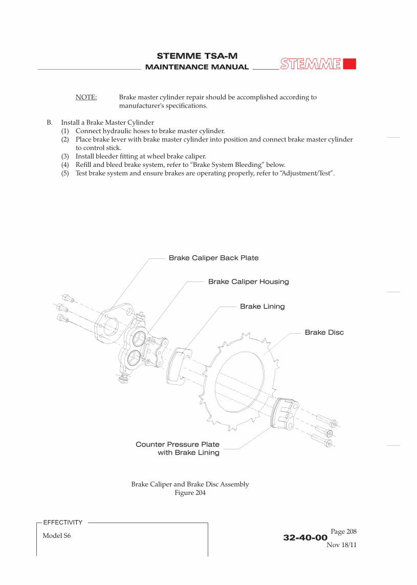
MAINTENANCE MANUAL
STEMME TSA-M
MAINTENANCE MANUAL
STEMME TSA-M
NOTE: Brake master cylinder repair should be accomplished according to manufacturer's specifications.
B. Install a Brake Master Cylinder(1) Connect hydraulic hoses to brake master cylinder.(2) Place brake lever with brake master cylinder into position and connect brake master cylinder
to control stick.(3) Install bleeder fitting at wheel brake caliper.(4) Refill and bleed brake system, refer to “Brake System Bleeding” below.(5) Test brake system and ensure brakes are operating properly, refer to “Adjustment/Test”.
6. Brake Caliper Removal/Installation
WARNING: CONTACT WITH HYDRAULIC FLUID CAN CAUSE SKIN IRRITATIONS.
CAUTION: EXCESSIVE HYDRAULIC FLUID WILL ATTACK THE SURFACE OF VARIOUS MATERIALS. READ AND ADHERE TO ALL MANUFACTURERS INSTRUCTIONS.PROVIDE A SUITABLE COLLECTING VESSEL FOR HYDRAULIC FLUID.
A. Remove a Caliper(1) Disconnect brake line at brake caliper and immediately plug or cap hydraulic fitting and
brake line.(2) Remove main gear wheels to get access to brake caliper back plate (refer to pt. 1).(3) Slide caliper housing with counter pressure plate and back plate inward away from the wheel
brake disc and remove caliper from the wheel.(4) Remove the three bolts that secure the brake caliper assembly to back plate and remove back
plate.
B. Install a Caliper(1) Install back plate to brake caliper assembly with three bolts. Pay attention to correct mounting
direction of back plate. Secure bolts with locking varnish. (2) Push back brake cylinder pistons with brake lining. Only use finger force. (3) Slide the caliper housing with brake cylinders, brake linings, counter pressure plate and back
plate onto the brake disc from wheel inward direction.(4) Install main gear wheels with brake caliper assembly and back plate to wheel axle and rocker
arm (refer to pt. 1).(5) Reconnect brake line to brake caliper.(6) Refill if necessary, and bleed brake system (refer to pt. 9).(7) Test brake system and ensure brakes are operating properly, refer to “Adjustment/Test”.
7. Brake Disc Removal/Installation
Minimum allowable brake disc thickness is 2.6 mm [1/10 in.].
A. Remove Brake Disc(1) Remove main gear wheel from main gear leg, refer to “Main Gear Wheels
Removal/Installation” (refer pt. 1) above.(2) Slide away brake caliper and remove from wheel to get full access to brake disc (refer to pt. 6).(3) Remove securing wire fixing the brake disc to wheel flange in axial direction.(4) Remove brake disc.
B. Install Brake Disc
NOTE: Before reinstalling the brake disc, inspect brake disc for camber and excessive scoring. Scoring should not be deeper than 0.5 mm [2/100 in.].
(1) Install brake disc to tooth system of main wheel flange.(2) Install securing wire around wheel flange brim to fix the brake disc to wheel flange in axial
direction.
32-40-00Page 209
32-40-00Page 208
Brake Caliper and Brake Disc AssemblyFigure 204
Brake Disc
Brake Caliper Housing
Counter Pressure Platewith Brake Lining
Brake Lining
Brake Caliper Back Plate
Nov 18/11Nov 18/11
EFFECTIVITY
Model S6
EFFECTIVITY
Model S6

MAINTENANCE MANUAL
STEMME TSA-M
MAINTENANCE MANUAL
STEMME TSA-M
(3) Install brake caliper assembly including back plate to brake disc (refer to pt. 6).(4) Install main gear wheel (refer to pt. 1).
8. Brake Lining / Brake Pads Replacement
Minimum allowable brake pads thickness (brake lining without base plate) is 1.0 mm [4/100 in.].
A. The following procedure describes the main steps for replacement of the BERINGER brake pads.For further information refer to manual MONT_PADS_1, Procedure to change brake pads on 2 piston caliper, latest revision of the BERINGER company.
B. Remove Brake Linings(1) Remove caliper from main gear wheel, as described in pt. 6.(2) Remove three bolts M8 fixing counter pressure plate to brake caliper housing assembly. If
necessary heat the caliper to 60-80°C [140-176°F] to loose the bolts.(3) Remove brake pads from pistons and counter pressure plate.(4) Clean around the pistons with a dry cloth.(5) Push back the two pistons with one finger (no force needed). If you cannot push back the
piston with one finger, the caliper must be checked and rebuilt.
C. Install Brake Lining(1) Position the new pads against pistons of caliper and second one against counter pressure
plate. Assemble caliper and counter pressure plate with brake pads in between.(2) Insert three bolts for assembling caliper, counter pressure plate and brake pads. Put blue
Loctite 243 on the end of each bolt.(3) Torque bolts to 25 Nm [220 lb.in]. Secure with locking varnish.(3) Reinstall brake caliper assembly to main gear wheel (refer to pt. 6).
9. Brake Hoses Replacement
WARNING: CONTACT WITH HYDRAULIC FLUID CAN CAUSE SKIN IRRITATIONS.
CAUTION: EXCESSIVE HYDRAULIC FLUID WILL ATTACK THE SURFACE OF VARIOUS MATERIALS. READ AND ADHERE TO ALL MANUFACTURERS INSTRUCTIONS.PROVIDE A SUITABLE COLLECTING VESSEL FOR HYDRAULIC FLUID.
A. Remove Brake Hoses(1) Remove left and right center fuselage cowlings and lower cowling (refer to 06-30-00 and
71-10-00).(2) Remove seats, lower seat coverings and front fuselage tunnel cover (refer to 25-10-00 and
25-21-00).(3) Place some cloth below the particular brake hoses area to absorb potentially dripping brake
fluid.(4) Empty the hydraulic fluid reservoir using a pipette to minimize the potentially dripping
brake fluid volume.
NOTE: The hydraulic fluid reservoir is located at the pilot's brake lever or if installed (optionally) at the co-pilot's brake lever.
32-40-00Page 210
(5) Remove/loosen clamp holders attaching brake hoses to main landing gear legs, control stick and to aircraft structure.
(6) Disconnect brake hoses on both ends from brake system components.(7) Remove/replace brake hoses one after another.(8) Pull out brake hoses from front fusealge structure (below seat bulkhead) carefully.(9) Remove brake hoses from aircraft.
B. Install Brake Hoses(1) Fit new cable protection to particular brake hoses with contact to structure.(2) Install brake hoses to airframe. Lead front fuselage brake hoses through seat bulkhead. Pay
attention to correct routing.(3) Install clamp holders attaching brake hoses to main landing gear legs, control stick and to
aircraft structure.(4) Connect brake hoses on both ends to brake system components.(5) Install front fuselage tunnel cover, lower seat coverings and seats (refer to 25-10-00 and
25-21-00).(6) Install center fuselage cowlings (refer to 06-30-00 and 71-10-00).(7) Replenish brake system (refer to 12-15-00).(8) Bleed brake system (refer to pt. 10).(9) Perform functional test.
10. Brake System Bleeding
A. After any maintenance at the brake system (component replacement etc.), or in case of non-correct function of the system because of trapped air, the system must be bled.
B. Tools, Equipment and Material
Required Quantity Equipment Parts No. Supplierin
3.A 1 Transparent PVC Hose, 3 m (9.8 ft.) HZ-KSL 041 Stemme3.A 1 Transparent PVC Hose, 10 cm (4 in.) HZ-KSL 041 Stemme3.A AR Hydraulic Fluid DOT 4 - any
3.A 1 Syringe 150 – 250 ml - any
3.A 1 Spanner, Width 11 mm - any3.A 1 Torx Driver T15 - any3.A AR Cleaning Rags -3.A AR Cable Ties - any
C. Bleed the brake system as follows:
CAUTION: LAY CLEANING RAGS AROUND THE PILOT STICK BASE (IF THE CO-PILOT
STICK IS EQUIPPED WITH A BRAKE LEVER – AROUND THE CO-PILOT STICK
BASE) TO PROTECT CABIN INTERIOR AGAINST SOILING.
(1) Open the reservoir at the pilot stick (optional at the co-pilot stick) with a torx driver T15.(2) Connect the HZ-KSL041 hose (approx. 10 cm [4 in.]) to the syringe.
32-40-00Page 211
Nov 18/11Nov 18/11
EFFECTIVITY
Model S6
EFFECTIVITY
Model S6

MAINTENANCE MANUAL
STEMME TSA-M
MAINTENANCE MANUAL
STEMME TSA-M
(3) Fill the syringe with DOT4.(5) Check all fittings for firm fit.(6) Connect the syringe to the right main wheel bleeder valve (the most far point in relation to the
reservoir).(7) Open bleeder valve with spanner (11 mm ) and pump hydraulic fluid into system until the fluid
level in the reservoir rises.(8) Close bleeder valve at the right main wheel.(9) Fill the long hose (approx. 3m [9.8 ft.]) completely with hydraulic fluid.(10) Connect the hose to the bleeder valve at the right main wheel.(11) Lay the other hose end into the reservoir and fix it by suitable means to prevent it from falling
(e.g. tape or cable tie).(12) Observing the fluid in the brake system reservoir, press the brake lever several times until air
bubbles cease to appear. Make sure the reservoir doesn't become empty. Refill hydraulic fluid on time.
CAUTION: AVOID OVERFILLING OF THE RESERVOIR! THIS CAN CAUSE SOILING OR DAMAGE TO THE COCKPIT EQUIPMENT.
(13) Close bleeder valve at the right main wheel.(14) Connect the filled with hydraulic fluid hose to the bleeder valve at the left main wheel.(15) Repeat steps 11 thru 13.(16) If required repeat bleeding procedure at the right main wheel.
NOTE: If both sticks are equipped with a brake lever (option), remove the brake lever from the pilot stick and lay it down horizontally in the cockpit. Do not disconnect the fluid lines!Then, during bleeding procedure move this brake lever some times slightly to remove trapped air from the lever system itself.Install brake lever after bleeding procedure is completed.
11. Adjustment/Test
A. There is no need to adjust the brakes since the brake pistons move to compensate for brake and wear.
B. After component replacement or repair:(1) Check the brakes for firm brake lever pressure and bleed the system if either brake feels spongy.(2) Perform a minimum of six stops from a speed of between 45 and 75 km/h [25 and 40 kts], using
light brake lever effort and letting the brakes cool partially (about one minute) between stops. Check the aircraft is not turning from centerline while apply brake lever.
(3) Check all fittings and hoses for any leakage.
32-40-00Page 212
CHAPTER 32
LANDING GEAR
Nov 18/11
EFFECTIVITY
Model S6-RT
EFFECTIVITY
Model S6
MAINTENANCE MANUAL
STEMME TSA-M
MAINTENANCE MANUAL
STEMME TSA-M
(3) Fill the syringe with DOT4.(5) Check all fittings for firm fit.(6) Connect the syringe to the right main wheel bleeder valve (the most far point in relation to the
reservoir).(7) Open bleeder valve with spanner (11 mm ) and pump hydraulic fluid into system until the fluid
level in the reservoir rises.(8) Close bleeder valve at the right main wheel.(9) Fill the long hose (approx. 3m [9.8 ft.]) completely with hydraulic fluid.(10) Connect the hose to the bleeder valve at the right main wheel.(11) Lay the other hose end into the reservoir and fix it by suitable means to prevent it from falling
(e.g. tape or cable tie).(12) Observing the fluid in the brake system reservoir, press the brake lever several times until air
bubbles cease to appear. Make sure the reservoir doesn't become empty. Refill hydraulic fluid on time.
CAUTION: AVOID OVERFILLING OF THE RESERVOIR! THIS CAN CAUSE SOILING OR DAMAGE TO THE COCKPIT EQUIPMENT.
(13) Close bleeder valve at the right main wheel.(14) Connect the filled with hydraulic fluid hose to the bleeder valve at the left main wheel.(15) Repeat steps 11 thru 13.(16) If required repeat bleeding procedure at the right main wheel.
NOTE: If both sticks are equipped with a brake lever (option), remove the brake lever from the pilot stick and lay it down horizontally in the cockpit. Do not disconnect the fluid lines!Then, during bleeding procedure move this brake lever some times slightly to remove trapped air from the lever system itself.Install brake lever after bleeding procedure is completed.
11. Adjustment/Test
A. There is no need to adjust the brakes since the brake pistons move to compensate for brake and wear.
B. After component replacement or repair:(1) Check the brakes for firm brake lever pressure and bleed the system if either brake feels spongy.(2) Perform a minimum of six stops from a speed of between 45 and 75 km/h [25 and 40 kts], using
light brake lever effort and letting the brakes cool partially (about one minute) between stops. Check the aircraft is not turning from centerline while apply brake lever.
(3) Check all fittings and hoses for any leakage.
32-40-00Page 212
CHAPTER 32
LANDING GEAR
Nov 18/11
EFFECTIVITY
Model S6-RT
EFFECTIVITY
Model S6

MAINTENANCE MANUAL
STEMME TSA-M
MAINTENANCE MANUAL
STEMME TSA-M
Page 0132 - TOC
TABLE OF CONTENTS
ChapterSection
Title Subject Page
LANDING GEAR - GENERAL ........................................................................32-00-00 1Introduction 32-00-00 1General Description 32-00-00 1
LANDING GEAR - GENERAL MAINTENANCE INSTRUCTIONS ........32-00-00 201Hydraulic Fluid General Instructions 32-00-00 201
MAIN GEAR - DESCRIPTION........................................................................32-10-00 1Introduction 32-10-00 1Description and Operation 32-10-00 1
MAIN GEAR - MAINTENANCE PRACTICES..............................................32-10-00 201Main Gear Leg Removal/Installation 32-10-00 201Elastomer Parts Removal/Installation 32-10-00 203
NOSE GEAR - DESCRIPTION........................................................................32-20-00 1Introduction 32-20-00 1Description and Operation 32-20-00 1
NOSE GEAR - MAINTENANCE PRACTICES..............................................32-20-00 201Nose Gear Leg Removal/Installation 32-20-00 201Elastomer Parts Removal/Installation 32-20-00 201Ultra-Bushing Removal/Installation 32-20-00 201
EXTENSION AND RETRACTION - DESCRIPTION ..................................32-30-00 1Introduction 32-30-00 1Description and Operation 32-30-00 1
EXTENSION AND RETRACTION - MAINTENANCE PRACTICES........32-30-00 201General 32-30-00 201Fill Hydraulic System and Oil Change 32-30-00 201Bleed Hydraulic System 32-30-00 203Oil Hoses Removal/Installation 32-30-00 203Hydraulic Cylinders Removal/Installation 32-30-00 205Pressure Accumulator Removal/Installation 32-30-00 205
LANDING GEAR DOORS - DESCRIPTION............................................... 32-31-00 1Introduction 32-31-00 1Description and Operation 32-31-00 1
LANDING GEAR DOORS - MAINTENANCE PRACTICES......................32-31-00 201Landing Gear Door Removal/Installation 32-31-00 201
Nov 18/11
EFFECTIVITY
Model S6-RT

MAINTENANCE MANUAL
STEMME TSA-M
MAINTENANCE MANUAL
STEMME TSA-M
WHEELS AND BRAKES - DESCRIPTION....................................................32-40-00 1Introduction 32-40-00 1Description and Operation 32-40-00 1
WHEELS AND BRAKES - MAINTENANCE PRACTICES .........................32-40-00 201General 32-40-00 201Tools, Equipment and Material 32-40-00 201Main Gear Wheels Removal/Installation 32-40-00 201Main Gear Wheel Disassembly/Assembly 32-40-00 201Nose Gear Wheel Removal/Installation 32-40-00 207Nose Gear Wheel Disassembly/Assembly 32-40-00 207Brake Master Cylinder Removal/Installation 32-40-00 207Brake Caliper Removal/Installation 32-40-00 209Brake Disc Removal/Installation 32-40-00 209Brake Lining Replacement 32-40-00 210Brake Hoses Replacement 32-40-00 210Brake System Bleeding 32-40-00 211Adjustment/Test 32-40-00 212
32 - TOCPage 02
TABLE OF CONTENTS (Continued)
ChapterSection
Title Subject Page
Nov 18/1132-00-00
Page 01
LANDING GEAR - GENERAL
1. Introduction
A. This chapter describes units and components, which furnish a means of supporting and steering the aircraft on the ground. Includes main and nose landing gears, brakes, wheels, tires and the landing gear doors.
2. General Description
A. The STEMME S6 has a retractable tricycle-configuration landing gear with a steerable nose gear. In the retracted configuration, all three landing gear legs are completely covered by landing
gear doors. The landing gear mechanics for retraction and extension are driven hydraulical.The struts of the main-landing-gear are welded tubes, which are stiff to torque. They are connected to the central steel-tube-framework of the mid-section of the fuselage by retracting mechanisms. The elastically mounted main-wheels are located at the end of rockers, which in turn are supported by elastomer-dampened springs.The nose-gear is made of a steel-strut which is stiff to torque. It is attached to the forward fuselage-section at an attachment-plate by screws and a drag brace for retracting mechanics. The shock-strut is dampened by the use of elastomers. In the extended position the nose-wheel is steered by rotating the nose-wheel-fork, which is attached to the shock-strut. This rotation is performed with several levers. When the nose-gear is extended and loaded, it is automatically connected to the rudder-controls to provide ground control. In the un-loaded position, it is automatically disconnected from the rudder-controls and locks for retraction in the direction of the longitudinal-axis.Hydraulically actuated dual-piston disc type brakes are provided on the main gear wheels on the inboard side. To prevent the brakes from unwanted locking, the brake-circuit is equipped with an anti-lock-regulator, which is mounted in the mid-section of the fuselage.
The extension and retraction of the main landing gear is realized for both landing gear legs with hydraulic cylinders. The safe and rapid extension of the main landing gear is triggered by actuating the emergency-extension-handle. In this case the extension process occurs by a gas accumulator for each landing gear leg strengthened by their tare weight. In the extended end position, the supporting strut is secured by a deadlock blocking and additional springs.
B. Descriptive Data
Wheel Base: 1970 mm (6,5 ft)Wheel Track: 1889 mm (6,2 ft)Main Tire Size: 5.00-5Nose Tire size: 4.00-5Main Tire Pressure: 3.5 ± 0.1 bar / 51.0 ± 1.5 p.s.i.Nose Tire Pressure: 3.5 ± 0.2 bar / 51.0 ± 3.0 p.s.i.
EFFECTIVITY
Model S6-RT
Nov 18/11
EFFECTIVITY
Model S6-RT

MAINTENANCE MANUAL
STEMME TSA-M
MAINTENANCE MANUAL
STEMME TSA-M
LANDING GEAR - GENERAL MAINTENANCE INSTRUCTIONS
1. Hydraulic Fluid General Instructions
WARNING: CONTACT WITH HYDRAULIC FLUID CAN CAUSE SKIN IRRITATIONS.
CAUTION: EXCESSIVE HYDRAULIC FLUID WILL ATTACK THE SURFACE OF VARIOUS MATERIALS. READ AND ADHERE TO ALL MANUFACTURERS INSTRUCTIONS OF USED HYDRAULIC FLUID.PROVIDE A SUITABLE COLLECTING VESSEL FOR HYDRAULIC FLUID.
A. Work with hydraulic fluid only in designated areas.
B. Hydraulic fluids must only get in contact with materials approved for this purpose.
C. Hydraulic fluids must not be spilled in order to prevent environmental and especiallygroundwater contamination.Normal pavement can also be affected by hydraulic fluid.
D. Hydraulic fluids must be kept away from moisture and any water-containing fluid, since thiscauses hydrolysis.The freed up acids may affect metals and plastics.
E. The safety instructions must be followed. Refer to the safety data sheet of used hydraulic fluid.Required protective clothing including gloves and face protection if applicable haveto be applied before beginning to work with hydraulic fluid.
F. Hydraulic fluids may be flammable (depending on used type). Appropriate safety precautionshave to be taken.
G. Hydraulic fluids of different types (especially synthetic and mineral fluid types) must not bemixed.
32-00-00Page 201
Nov 18/11
EFFECTIVITY
Model S6-RT

MAINTENANCE MANUAL
STEMME TSA-M
MAINTENANCE MANUAL
STEMME TSA-M
32-10-00Page 01
MAIN LANDING GEAR - DESCRIPTION
1. Introduction
A. The S6 main landing gear consists of the main landing gear struts, the wheels with brakes, the hydraulic driven retracting mechanism and the main landing gear doors. The struts of the main-landing-gear are welded tubes. They are made of high-strength steel, which makes them stiff to torque and carry the landing loads. They are connected to the central steel-tube-framework of the mid-section of the fuselage. The STEMME S6 is equipped in series with dual-piston disc type brakes.
2. Description and Operation
A. Each main landing gear strut is attached to the center fuselage steel frame by one main bearing, a stiff strut and a drag strut for retraction of the landing gear leg. All brackets are bolted to the mounting points of the center fuselage steel frame-work. To the main bearing the struts are mounted with a special bolt-bushing-bearing including main attachment bolt.The elastically mounted main-wheels are located at the end of rockers, which in turn are supported by elastomer-dampened springs. The maximum spring-travel of the main-gear is approx. 150mm (6 in). The rockers are attached to the lower end of the landing gear strut with a rolling contact joint and a main bolt. The wheel axle itself is welded to the end of the rocker. A mounting plate for the disc brake assembly is attached to the inner surface of the axle and bolted as counter-bearing to the wheel rocker.
Nov 18/11
EFFECTIVITY
Model S6-RT

MAINTENANCE MANUAL
STEMME TSA-M
MAINTENANCE MANUAL
STEMME TSA-M
MAIN LANDING GEAR - MAINTENANCE
1. Main Landing Gear Leg Removal/Installation (Refer to Figure 201)
WARNING: CONTACT WITH HYDRAULIC FLUID CAN CAUSE SKIN IRRITATIONS.
CAUTION: FOR ANY MAINTENANCE PROCEDURES ON THE LANDING GEAR THE AIRCRAFT HAS TO BE HANGED ON A CRANE OR SUPPORTED WITH AN UNDER-WING LIFT DEVICE.
EXCESSIVE HYDRAULIC FLUID WILL ATTACK THE SURFACE OF VARIOUS MATERIALS. READ AND ADHERE TO ALL MANUFACTURERS INSTRUCTIONS.PROVIDE A SUITABLE COLLECTING VESSEL FOR HYDRAULIC FLUID.
A. Remove a Main Landing Gear Leg(1) Gain access to the landing gear mounting brackets in the fuselage belly (refer to 25-00-00).(2) Lift aircraft (refer to 07-10-00).(3) Remove main landing gear doors (refer to 32-31-00).(4) Disconnect brake line at fitting on strut. Insert a plug into disconnected fittings immediately
to prevent loosing breaking fluid.(5) Unhinge hydraulic cylinder (refer to 32-30-00).(6) Remove tension spring.(7) Loosen drag brace.(8) Remove attachment bolt from main landing gear strut in the steel frame.(9) Loosen main bolt of hinged joint securing main landing gear leg to center fuselage steel
frame.(10) Pull main landing gear leg from center fuselage steel frame.
B. Install a Main Landing Gear Leg(1) Place main landing gear leg into position in the fuselage belly and insert main bolt and self-
securing nut of hinged joint.Pay attention to correct installation of all joint parts and washer.
(2) Install bolts to the main landing gear struts.(3) Tighten main bolt and bolts on struts securing main gear leg to center fuselage steel frame
and secure all nuts with locking varnish.(4) Install drag brace and secure nut with locking varnish.(5) Install tension spring(6) Install hydraulic cylinder.(7) Reconnect brake line.(8) Install main landing gear doors.(9) Refill and bleed brake system.(10) Ensure the brake system is operating properly.
32-10-00Page 201
32-10-00Page 02
Main Gear Leg InstallationFigure 01
ADetail-
A
May 04/12 Nov 18/11
EFFECTIVITY
Model S6-RT
EFFECTIVITY
Model S6-RT

MAINTENANCE MANUAL
STEMME TSA-M
MAINTENANCE MANUAL
STEMME TSA-M
ADetail-
A B
BDetail-
CDetail-
DDetail-
CD
Main Gear Leg InstallationFigure 201
32-10-00Page 203
32-10-00Page 202
EFFECTIVITY
Model S6-RT
EFFECTIVITY
Model S6-RT
2. Elastomer Parts Removal/Installation (Refer to Figure 202)
WARNING: CONTACT WITH HYDRAULIC FLUID CAN CAUSE SKIN IRRITATIONS.
CAUTION: EXCESSIVE HYDRAULIC FLUID WILL ATTACK THE SURFACE OF VARIOUS MATERIALS. READ AND ADHERE TO ALL MANUFACTURERS INSTRUCTIONS.PROVIDE A SUITABLE COLLECTING VESSEL FOR HYDRAULIC FLUID.
A. Remove Elastomer Parts(1) Remove main gear leg (refer to pt. 1).(2) Remove main gear wheel (refer to 32-40-00).
(4) Remove locking screws at upper main gear leg to release elastomer damper from adjustment.
B. Install Elastomer Parts(1) Thread elastomer elements and spacer discs of damper to guide cylinder of shock-strut. Pay
attention to correct sequence of the different elastomer elements for complete damper assembly.
(2) Install locking screws at upper main gear leg to fix elastomer damper-strut. (3) Secure locking screws.(4) Re-install lower bolt for damper - rocker arm connection.(5) Re-install main gear wheel (refer to 32-40-00).(6) Re-install main gear leg (refer to pt. 1).
(3) Remove lower bolt for damper - rocker arm connection.
Nov 18/11May 04/12

MAINTENANCE MANUAL
STEMME TSA-M
MAINTENANCE MANUAL
STEMME TSA-M
32-10-00Page 204
Main Gear Elastomer Damper and Deflector InstallationFigure 202
EFFECTIVITY
Model S6-RT
A
B
C
ADetail-
BDetail-
CDetail-
Nov 18/11