Embed Size (px)
Citation preview

Eur. Phys. J. C (2017) 77:901https://doi.org/10.1140/epjc/s10052-017-5456-7
Regular Article - Experimental Physics
Steering of Sub-GeV electrons by ultrashort Si and Ge bentcrystals
A. I. Sytov1,2, L. Bandiera1,a, D. De Salvador3,4, A. Mazzolari1, E. Bagli1, A. Berra6,7, S. Carturan3,4,C. Durighello1,3,4, G. Germogli1, V. Guidi1, P. Klag5, W. Lauth5, G. Maggioni3,4, M. Prest6,7, M. Romagnoni1,V. V. Tikhomirov2, E. Vallazza8
1 INFN Sezione di Ferrara, Dipartimento di Fisica e Scienze della Terra, Università di Ferrara Via Saragat 1, 44100 Ferrara, Italy2 Institute for Nuclear Problems, Belarusian State University, Bobruiskaya 11, 220030 Minsk, Belarus3 INFN Laboratori Nazionali di Legnaro, Viale dell’Università 2, 35020 Legnaro, Italy4 Dipartimento di Fisica, Università di Padova, Via Marzolo 8, 35131 Padova, Italy5 Institut für Kernphysik der Universität Mainz, 55099 Mainz, Germany6 Università dell’Insubria, via Valleggio 11, 22100 Como, Italy7 INFN Sezione di Milano Bicocca, Piazza della Scienza 3, 20126 Milan, Italy8 INFN Sezione di Trieste, Via Valerio 2, 34127 Trieste, Italy
Received: 6 September 2017 / Accepted: 12 December 2017 / Published online: 23 December 2017© The Author(s) 2017. This article is an open access publication
Abstract We report the observation of the steering of 855MeV electrons by bent silicon and germanium crystals at theMAinzer MIkrotron. Crystals with 15 µm of length, bentalong (111) planes, were exploited to investigate orienta-tional coherent effects. By using a piezo-actuated mechanicalholder, which allowed to remotely change the crystal curva-ture, it was possible to study the steering capability of planarchanneling and volume reflection vs. the curvature radius andthe atomic number, Z. For silicon, the channeling efficiencyexceeds 35%, a record for negatively charged particles. Thiswas possible due to the realization of a crystal with a thick-ness of the order of the dechanneling length. On the otherhand, for germanium the efficiency is slightly below 10%due to the stronger contribution of multiple scattering for ahigher-Z material. Nevertheless this is the first evidence ofnegative beam steering by planar channeling in a Ge crystal.Having determined for the first time the dechanneling length,one may design a Ge crystal based on such knowledge pro-viding nearly the same channeling efficiency of silicon. Thepresented results are relevant for crystal-based beam manip-ulation as well as for the generation of e.m. radiation in bentand periodically bent crystals.
Electronic supplementary material The online version of thisarticle (https://doi.org/10.1140/epjc/s10052-017-5456-7) containssupplementary material, which is available to authorized users.
a e-mail: [email protected]
1 Introduction
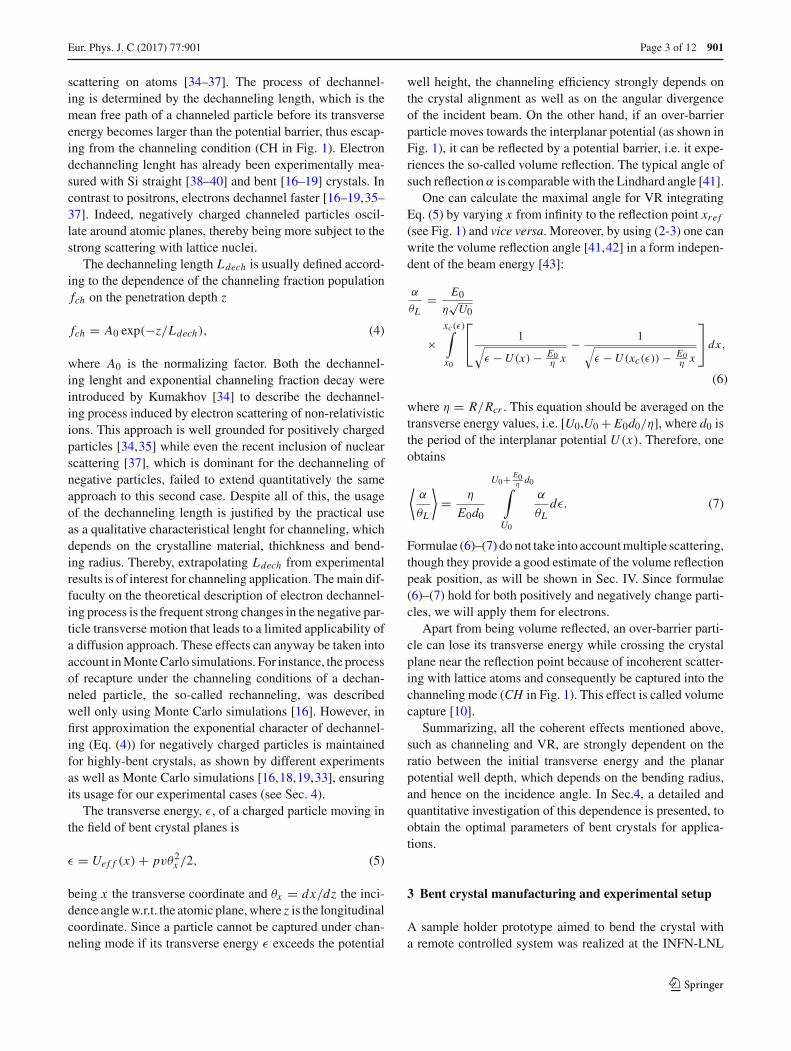
Beam steering based on the coherent interaction of chargedparticle beams with bent crystals found several applicationsin accelerator physics. In particular, crystal-based beam col-limation and extraction were successfully investigated at sev-eral accelerator machines, such as U70, SPS, RHIC, Tevatronand LHC [1–7]. The main idea of crystal-assisted beam steer-ing, firstly proposed by Tsyganov in 1976 [8], relies on pla-nar channeling [9], holding a charged particle in a potentialwell (see Fig. 1) formed by the electric field of two neigh-boring atomic planes. If a crystal is bent, charged beam willbe steered since its trajectory is confined under channelingconditions along bent crystal planes. Another coherent effectin a bent crystal, i.e., the so-called volume reflection (VR)[10], consists of the reversal of charged particle momentumby the potential barrier of a bent crystal plane. Figure 1 dis-plays the potential energy of the bent (111) plane Si (left) andGe (right) crystals. The figure also shows the potential wellin which a channeled particle is captured (marked as CH),while the red line with a double arrow depicts the reflectionof particle momentum under VR. Through VR, charged par-ticles are deflected to a smaller bending angle with respectto channeling, however this method provides a considerablylarger and adjustable angular acceptance, equal to the crystalcurvature, and higher deflection efficiency.
Over the years, positive particle beam steering has beenwell investigated in a wide range of energies, from fewMeV up to the recent result at LHC with 6.5 TeV protons.Conversely, the negatively charged particle case has been
123

901 Page 2 of 12 Eur. Phys. J. C (2017) 77 :901
Fig. 1 Interplanar potential of (111) Si and Ge crystals for maximal bending radii (4.76 cm and 1.83 cm respectively) used in the experiments
poorly investigated and only recently, thanks to the realiza-tion of very short bent Si crystals [11], it has become pos-sible to steer negatively charged particles beams [12–22].However, the possibility to steer electron beams is promis-ing for applications in electron-positron collider collimationsystems [14,23–26] as well as innovative high-intensity X -or γ -radiation sources [12–15,27].
Silicon is the most used prime material for the fabrica-tion of bent crystals due to its high-quality crystalline lat-tice and low cost. Nevertheless other prime materials, forinstance germanium, which can be supplied with a similarcrystalline quality, deserve investigation. Indeed, since a Gecrystal provides a stronger potential, due to its higher atomicnumber (Z), one can expect a higher angular acceptance forchanneling and an enhancement of e.m. radiation emission.Currently, few channeling experiments have been performedwith bent Ge, only with positively charged particles and onlyin the hundreds GeV energy range [28–31], while with elec-trons and at lower energies there are no data in literature dueto the technical difficulties of fabrication of an ultra-shortbent Ge crystal.
In this paper, we present an investigation on sub-GeV elec-tron steering with both silicon and germanium bent crystalsunder channeling and VR. With the aim of determining thedifferent behavior of these effects vs. the atomic number Z,two 15 µm Si and Ge crystals, bent along the (111) planes,were selected and an experiment was performed at the MainzMikrotron (MAMI) with 855 MeV electrons. We also inves-tigated the dependence of the channeling efficiency and ofthe dechanneling length, which is the main parameter for pla-nar channeling, on the crystal curvature for the first time withelectrons and absolutely for the first time with a germaniumcrystal.
2 Theory of channeling, dechanneling and volumereflection
For better understanding of this paper, we herewith providea brief summary of orientational coherent phenomena in abent crystal.
Planar channeling consists in the confinement of a chargedparticle trajectory by the electric field of crystal planes, whenthe particle transverse energy is smaller than the interplanarpotential barrier (see Fig. 1, where the model of Doyle-Ternerpotential [32] is applied), described as
Uef f (x) = U (x) + pvx/R, (1)
where U (x) is the interplanar potential for a straight crystal,p and v the particle momentum and velocity respectively,and R the bending radius. Channeling may occur when theparticle trajectory is nearly parallel to the crystal planes, moreprecisely for an incidence angle smaller than the Lindhardangle [9] defined as,
θL =√
2U0
pv, (2)
U0 being the potential well depth of a straight crystal. For 855MeV electrons at MAMI channeled in the (111) planes oneobtains the following values of the Lindhard angle: θL ,Si =232 µrad and θL ,Ge = 274 µrad, for Si and Ge, respectively.
If the crystal is bent, the well depth and the Lindhard angledecrease with R, going to zero for the critical radius:
Rcr = pv
E0, (3)
where E0 is the maximal value of the interplanar electricfield. For R ≤ Rcr channeling is forbidden. In case of 855MeV electrons moving in the field of (111) planes, the criticalradius is Rcr,Si = 1.59 mm and Rcr,Ge = 1 mm for Si andGe, respectively.
Channeling proved to be an efficient way to steer positiveparticle beams, achieving deflection efficiencies larger than80%. On the other hand, the maximal deflection efficiency forelectrons recorded in the literature slightly exceeds 20% [16]and is about 30% for negative pions [33]. The main sourceof inefficiency is dechanneling, which consists in particlesescaping from the channeling mode caused by Coulomb
123
Eur. Phys. J. C (2017) 77 :901 Page 3 of 12 901
scattering on atoms [34–37]. The process of dechannel-ing is determined by the dechanneling length, which is themean free path of a channeled particle before its transverseenergy becomes larger than the potential barrier, thus escap-ing from the channeling condition (CH in Fig. 1). Electrondechanneling lenght has already been experimentally mea-sured with Si straight [38–40] and bent [16–19] crystals. Incontrast to positrons, electrons dechannel faster [16–19,35–37]. Indeed, negatively charged channeled particles oscil-late around atomic planes, thereby being more subject to thestrong scattering with lattice nuclei.
The dechanneling length Ldech is usually defined accord-ing to the dependence of the channeling fraction populationfch on the penetration depth z
fch = A0 exp(−z/Ldech), (4)
where A0 is the normalizing factor. Both the dechannel-ing lenght and exponential channeling fraction decay wereintroduced by Kumakhov [34] to describe the dechannel-ing process induced by electron scattering of non-relativisticions. This approach is well grounded for positively chargedparticles [34,35] while even the recent inclusion of nuclearscattering [37], which is dominant for the dechanneling ofnegative particles, failed to extend quantitatively the sameapproach to this second case. Despite all of this, the usageof the dechanneling length is justified by the practical useas a qualitative characteristical lenght for channeling, whichdepends on the crystalline material, thichkness and bend-ing radius. Thereby, extrapolating Ldech from experimentalresults is of interest for channeling application. The main dif-fuculty on the theoretical description of electron dechannel-ing process is the frequent strong changes in the negative par-ticle transverse motion that leads to a limited applicability ofa diffusion approach. These effects can anyway be taken intoaccount in Monte Carlo simulations. For instance, the processof recapture under the channeling conditions of a dechan-neled particle, the so-called rechanneling, was describedwell only using Monte Carlo simulations [16]. However, infirst approximation the exponential character of dechannel-ing (Eq. (4)) for negatively charged particles is maintainedfor highly-bent crystals, as shown by different experimentsas well as Monte Carlo simulations [16,18,19,33], ensuringits usage for our experimental cases (see Sec. 4).
The transverse energy, ε, of a charged particle moving inthe field of bent crystal planes is
ε = Uef f (x) + pvθ2x /2, (5)
being x the transverse coordinate and θx = dx/dz the inci-dence angle w.r.t. the atomic plane, where z is the longitudinalcoordinate. Since a particle cannot be captured under chan-neling mode if its transverse energy ε exceeds the potential
well height, the channeling efficiency strongly depends onthe crystal alignment as well as on the angular divergenceof the incident beam. On the other hand, if an over-barrierparticle moves towards the interplanar potential (as shown inFig. 1), it can be reflected by a potential barrier, i.e. it expe-riences the so-called volume reflection. The typical angle ofsuch reflection α is comparable with the Lindhard angle [41].
One can calculate the maximal angle for VR integratingEq. (5) by varying x from infinity to the reflection point xre f(see Fig. 1) and vice versa. Moreover, by using (2-3) one canwrite the volume reflection angle [41,42] in a form indepen-dent of the beam energy [43]:
α
θL= E0
η√U0
×xc(ε)∫x0
⎡⎣ 1√
ε −U (x) − E0η x
− 1√ε −U (xc(ε)) − E0
η x
⎤⎦ dx,
(6)
where η = R/Rcr . This equation should be averaged on thetransverse energy values, i.e. [U0,U0 + E0d0/η], where d0 isthe period of the interplanar potential U (x). Therefore, oneobtains
⟨α
θL
⟩= η
E0d0
U0+ E0ηd0∫
U0
α
θLdε. (7)
Formulae (6)–(7) do not take into account multiple scattering,though they provide a good estimate of the volume reflectionpeak position, as will be shown in Sec. IV. Since formulae(6)–(7) hold for both positively and negatively change parti-cles, we will apply them for electrons.
Apart from being volume reflected, an over-barrier parti-cle can lose its transverse energy while crossing the crystalplane near the reflection point because of incoherent scatter-ing with lattice atoms and consequently be captured into thechanneling mode (CH in Fig. 1). This effect is called volumecapture [10].
Summarizing, all the coherent effects mentioned above,such as channeling and VR, are strongly dependent on theratio between the initial transverse energy and the planarpotential well depth, which depends on the bending radius,and hence on the incidence angle. In Sec.4, a detailed andquantitative investigation of this dependence is presented, toobtain the optimal parameters of bent crystals for applica-tions.
3 Bent crystal manufacturing and experimental setup
A sample holder prototype aimed to bend the crystal witha remote controlled system was realized at the INFN-LNL
123
901 Page 4 of 12 Eur. Phys. J. C (2017) 77 :901
lab in Legnaro, Italy. This innovative holder permitted toexperimentally investigate important bent crystal parametersfor application, such as the channeling and VR deflectionangle and efficiency and the dechanneling length as a func-tion of the curvature radius R, without manually re-bendingthe crystal. The curvature can be smoothly increased witha numerical control to avoid stress concentrations and thuspreventing the sample breaking, since the mounting and thebending steps are decoupled. Another advantage with respectto previously used static holders is the possibility to remotelycorrect distorsion. Indeed, if the sample curvature is not per-fect, the incoming angle for channeling could vary along thebeam dimension (i.e. a local torsion) causing a detrimentaleffect on efficiency [44]. The correction system is an addi-tional degree of freedom which allows to compensate localtorsion during the channeling experiment, while checking inreal time the effect on the efficiency.
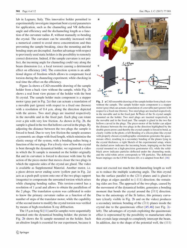
Figure 2a shows a CAD ensemble drawing of the sampleholder from a back view without the sample, while Fig. 2bshows a real front view picture of the holder with the bentSi crystal. The sample holder main component is a steppermotor (gray part in Fig. 2a) that can actuate a translation ofa movable part (green) with respect to a fixed one (brown)with a resolution of 0.4 µm, along the direction depictedwith the arrows. Two steel plugs are inserted respectivelyin the movable and in the fixed part. Each plug can rotateover a pin with very low friction. As shown in Fig. 2b, thesample is glued in the two flat hollows carved in the plugs. Byadjusting the distance between the two plugs the sample isforced to bend. Due to very low friction the sample assumesa symmetric arc shape with fixed length, which minimize theelastic energy of the system, with a bending radius being afunction of the two plugs. For a lively view of how the crystalis bent through the dynamical holder, we registered a videoin which the Si sample is mounted on the holder originallyflat and its curvature is forced to decrease with time by theaction of the piezo-motor that moves closer the two plugs inwhich the opposite sides of the crystal are glued. The videois available as Supplemental Material. Another motor, i.e.a piezo driven never ending screw (yellow part in Fig. 2a)acts as a push-pull system onto one of the two plugs support(magenta) to compensate the unwanted torsion which ariseswhile changing bending radius. This torsion-control has aresolution of 1 µrad and allows to obtain the parallelism ofthe 2 plugs. The translation system was calibrated in orderto know the primary curvature radius as a function of thenumber of steps of the translator motor, while the capabilityof the second motor to modify the crystal torsion was verifiedby means of high-resolution X-ray diffraction.
The 15µm long Si [11] and Ge samples were sequentiallymounted onto the dynamical bending holder; the picture inFig. 2b shows the Si sample mounted on the holder. Suchan ultralow length is essential for our experiment, because it
lcr=15
6020
c
a b
Fig. 2 aCAD ensemble drawing of the sample holder from a back viewwithout the sample. The sample holder main component is a steppermotor (gray) that can actuate a translation of a movable part (green) withrespect to a fixed one (brown). Two steel plugs are inserted respectivelyin the movable and in the fixed part. b Photo of the Si crystal samplemounted on the holder. Two steel plugs are inserted respectively inthe movable and in the fixed part. The sample is glued in the two flathollows carved in the plugs. The piezo-motor of the holder can adjustthe distance between the two plugs in the direction highlighted by thedouble green arrows and thereby the crystal sample is forced to bend, asclearly visible in the photo. c left Bending of a silicon plate-like crystalwith properly chosen crystallographic orientations generates the quasi-mosaic effect, resulting in a secondary bending of the planes lying inthe crystal thickness. c right Sketch of the experimental setup, wherethe dashed arrow indicates the incoming beam, impinging on the bentcrystal mounted on a high-precision goniometer (G), while the solid-black arrow indicates particles deflected under the channeling mode,and the solid-white arrow corresponds to VR particles. The deflectedbeam impinges on the LYSO Screen (D). c is adapted from Ref. [16]
must not exceed too much the dechanneling length as wellas to reduce the multiple scattering angle. The thin crystalhas the surface parallel to the (211) planes and is glued tothe plugs at edges parallel to [-111] direction; the remain-ing sides are free. The approach of the two plugs, caused bythe movement of the dynamical holder, generates a bendingmoment that bends the crystal around the [1̄11] direction.Due to the anisotropy of the Si lattice, this primary curva-ture (clearly visible in Fig. 2b and on the video) producesa secondary intrinsic bending of the (1̄11) planes inside thecrystal due to the quasimosaic effect [45,46] (see Fig. 2c-left). The advantages of crystals exploiting the quasimosaiceffect is represented by the possibility to manufacture ultrathin crystals large enough to completely intercept the beam.In addition, due to the shape of the potential well, the (111)
123

Eur. Phys. J. C (2017) 77 :901 Page 5 of 12 901
bent planes (see Fig. 1) are the most efficient for the deflectionof negatively charged particles. The anticlastic effect couldbe a drawback of quasimosaic bent crystals but in the caseof the present data, the large bending and small thicknessguarantee a complete anticlastic suppression as demonstratein [47]. This was checked by high resolution X-ray diffrac-tion by measuring the (111) orientation at different positionsalong the y-axis. No anticlastic trend was evidenced with anexception of about 2 mm close to the sample border. On theother hand, a residual variation of the (111) plane orientationof about ± 50 µrad inside the dimension of the measuringX-ray beam (100 µm) was evidenced. This is interpreted asa residual sample rippling induced by imperfections causedby the glueing procedure.
An experiment was carried out in the Hall B of the MainzerMikrotron (MAMI) with 855 MeV electrons. The experi-mental setup is the same as in [48] with the substitutionof the Si microstrip detector to measure the beam profileafter the interaction with the crystal with a LYSO Screen(see Fig. 2c). The screen has a thickness of 200 µm andis inclined of 22.5◦ toward the camera in the perpendicu-lar direction with respect to the beam deflection plane andwas placed downstream the crystal of 6020 mm. The crys-tal holder was mounted on a high-precision goniometer with5 degrees of freedom. Translations along the x and y axeswere used to geometrically align the crystal with the beamdirection, while rotations around the x, y and z axes with anaccuracy of 17.5, 30, and 50 µrad respectively, were usedto achieve angular alignment of the crystal planes with theelectron beam. The entire experimental setup was kept undervacuum to avoid multiple scattering of the beam by air. Thebeam was focused through dedicated quadrupole lenses: theresulting beam size and angular divergence were 105µm and21µrad along the vertical direction, which is the crystal bend-ing direction. The beam divergence is smaller of the Lindardcritical angle for channeling, which is about 220 µrad at 855MeV. A schematic view of the experimental setup is shownin Fig. 2c: it allows to characterize, with very high precision,Si and Ge crystals in terms of both deflection efficiency anddechanneling length.
4 Experimental results and analysis
By exploiting the dynamical bending holder, we tested chan-neling and VR of 855 MeV electrons for four and three dif-ferent curvatures in case of Si and Ge crystals, respectively.For each bending radius, R, we measured the distribution ofthe particles angles θx after the interaction with the crystalvs. crystal-to-beam orientation, θcr , by rotating the goniome-ter around the ideal alignment with bent (111) planes. As anexample, the experimental angular scan for the silicon crys-tal with a deflection angle of θb = 315 µrad and the germa-
nium crystal of θb = 820 µrad are shown in Fig. 3. Figure 4shows the beam deflection distributions with Si and Ge crys-tals oriented in channeling and in the middle of VR region,for the angular position highlighted by dashed lines in Fig.3. These plots allow one to follow the transition betweenthe main processes occurring while changing the crystal-to-beam orientation. In the angular distributions for channelingorientation (θcr = 0) the right peak represents the chan-neling mode as well as the left one is for the over-barrierparticles. By decreasing θcr to about the middle of the range[−θb+θL ;−θL ] one sets up the VR orientation. At the latter,the right peak represents volume captured particles. Finally, acrystal alignment beyond this range suppresses all the coher-ent effects, leading to the “amorphous” region where multiplescattering dominates.
The crystal bending angle and alignment has been mea-sured experimentally and verified by computer simulationsusing the CRYSTAL simulation code [49,50]. This simula-tion code is developed for ab-initio Monte Carlo simulationsof charged particle trajectories in an interplanar or inter-axial potential in a crystalline medium (either bent or not)with both multiple and single scattering on nuclei and elec-trons. The method developed by the code has already beentested vs. experimental results in [12–14,16,51]. The perfectalignment with bent planes, i.e., θcr = 0, was experimen-tally determined by the highest intensity of the channelingpeak, recorded during the angular scan. The channeling peakposition also provided the crystal bending angle, verified byCRYSTAL simulations. The Monte Carlo simulations per-mitted to take into account the incoming angle distributionand sample rippling. The outcomes of the CRYSTAL codewith a statistics from 2 × 10⁶ up to 5 × 10⁶ particles aredisplayed in Figs. 3, 4 for comparison with experimentalmeasurements.
The analysis of the angular distributions was carried outthrough a fitting procedure based on the one presented inRefs. [17,18]. The fitting function represents the sum of thechanneling part, described by gaussian:
d fchdθX
= Ach
σch√
2πexp
(− (θX − θch)
2
2σ 2ch
), (8)
the volume reflection part, containing also a non-reflectedoverbarrier fraction and described by the sum of two gaus-sians:
d fV R
dθX= AV R
σV R√
2πexp
(− (θX − θV R)2
2σ 2V R
)
+ 1 − AV R
rσV R√
2πexp
(− (θX − θV R)2
2r2σ 2V R
), (9)
123

901 Page 6 of 12 Eur. Phys. J. C (2017) 77 :901
Fig. 3 Experimental (a, c) and simulated (b, d) angular scans. Deflec-tion angle vs. the crystal-to-beam orientation of Si (a, b) and Ge (c,d) crystals, bent at 315 µrad and 820 µrad respectively. Vertical white
dashed lines represent the central orientation of the channeling and vol-ume reflection distributions displayed in Fig. 4
and the dechanneling part, being an exponential distribution,convolved with the first gaussian in (9):
d fdechdθX
= Adech
2θdechexp
(σ 2V R
2θ2dech
+ θch − θX
θdech
)
×⎛⎝erf
⎛⎝ θV R−θX + σ 2
V Rθdech√
2σV R
⎞⎠−erf
⎛⎝ θch−θX + σ 2
V Rθdech√
2σV R
⎞⎠
⎞⎠ .
(10)
The total fitting function can be written as:
1
N
dN
dθX= d fch
dθX+ BV R
d fV R
dθX+ d fdech
dθX. (11)
In (8)–(11) Ach, AV R, BV R, Adech and r are the normal-izing factors, θch, θV R and σch, σV R the mean angles andthe standard deviations of corresponding gaussians respec-tively as well as θdech the “dechanneling angle”, defining thedechanneling length, found from the angular distribution,
as Ldech = Rθdech . The channeling efficiency is definedas the integral value of the gaussian fit of the channelingpeak (8), within ±3σch around the channeling peak, namelyηch ≈ 0.9973Ach .
The fit procedure was carried out in two steps. First, Eq.(9) was applied for the fit of the angular distribution of thecrystal, aligned in amorphous direction. The values AV R andr , extracted in the first step were used in the fit (11) [17,18].
The main difference with the fitting procedure from[17,18] are the coefficients Ach, BV R, Adech , treated inde-pendently. Though the increase of the free parameters num-ber reduces the accuracy, it is necessary in this case for acorrect description of initially overbarrier particles, as willbe explained later in the text.
In order to provide the most accurate simulation resultsas possible, the simulated channeling efficiency values weredirectly computed by using the CRYSTAL simulation codethrough the calculation of channeled (under-barrier) parti-cles population. The deflection efficiency obtained through
123

Eur. Phys. J. C (2017) 77 :901 Page 7 of 12 901
a b
c d
Fig. 4 Experimental (solid) and simulated (dashed) distributions ofdeflected beam by Si (a, b) and Ge (c, d) crystals, bent at 315 µradand 820 µrad respectively, for channeling (a, c) and volume reflection(b, d) crystal alignment. Experimental values represent the projection
of the beam spot collected by the screen along the vertical direction(y) of bending. Simulations were performed with a statistics of 5 · 106
particles for each plot
the fitting of simulated beam profiles is nearly the same cal-culated directly counting the number of under-barrier parti-cles for R/Rcr < 20, determining the goodness of the fittingprocedure (8)–(11) to estimate the deflection efficiency. Thelimitation of this procedure in the range R/Rcr > 20 is con-nected with the overlap of the channeling and over-barrierpeaks in the deflected beam profile for too high bending radiias explained later in the text.
The experimental results were critically compared toCRYSTAL simulations, highlighting a good agreementbetween them. The dependence of the channeling deflec-tion efficiency on the ratio R/Rcr is shown in Fig. 5 forboth experimental and simulation results. The errors on theexperimental efficiencies are due to the fitting error with anadditional uncertainty connected with the normalization pro-cedure. On the other hand, the x-error of simulated results isconnected with the uncertainty of the crystal length, whilethe small y-error is due to statistics. Table 1 displays allvalues of the curvature radii, bending angles, θb, and chan-neling efficiency used in the experiment; Table 2 representsthe same results obtained with simulations. As expected,the dependence of channeling efficiency is monotonic [52],since the potential well depth decreases while R becomessmaller.
The experimental results highlighted a channeling effi-ciency larger than 35% for silicon in agreement with sim-ulations. Through the fitting procedure (8)–(11) it was notpossible to extract the dechanneling length for silicon in thecase R/Rc > 20, while the channeling efficiency valueswas found with very large errors as explained later in thetext. The experimental error is rather high for the curvatureof θb = 315µrad, because channeling and volume reflec-tion peaks are very close, and it is difficult to distinguishthe channeling fraction. By this reason, the angular distancebetween the channeling and volume reflection peaks is themain restriction of the fit (8)–(11). Nevertheless, it is clearfrom Fig. 4 upper left that high-efficiencies as those in thispaper have never been achieved so far for electrons.
On the other hand, channeling efficiency for germaniumachieves 8% at the lowest experimental bending angle. Thisis indeed the first evidence of negative beam deflection viachanneling in a bent Ge crystal.
Although, channeling efficiency for germanium is muchlower than for silicon, this effect should not be attributed tothe quality of the crystal, because both germanium and sili-con crystals were manufactured through the same proceduresleading to high performance of both crystals at much higherenergy [29–31]. The only reason for such a difference owes
123

901 Page 8 of 12 Eur. Phys. J. C (2017) 77 :901
Si, simulationSi, experiment
Ge, simulationGe, experiment
0 5 10 15 20 25 30 350.0
0.1
0.2
0.3
0.4
0.5
0.6
R Rcr
chη
Fig. 5 The experimental and simulated depedences of channeling effi-ciency of Si and Ge crystals at optimal channeling orientation on theratio of the bending radius to its critical value
Table 1 Measured Si and Ge crystal bending radia, angles and chan-neling efficiency
Material θb(µrad) RRcr
θV R(µrad) ηch
Si 315 29.9 224 0.40 ± 0.08
Si 550 17.1 204 0.248 ± 0.016
Si 750 12.6 194 0.206 ± 0.013
Si 1080 8.72 183 0.165 ± 0.010
Ge 820 18.3 172 0.084 ± 0.017
Ge 1200 12.5 165 0.036 ± 0.007
Ge 1430 10.4 162 0.019 ± 0.004
Table 2 Simulated Si and Ge crystal bending radia, angles and chan-neling efficiency
Material θb(µrad) RRcr
θV R(µrad) ηch
Si 315 29.9 235 0.3818 ± 0.0004
Si 550 17.1 203 0.3000 ± 0.0004
Si 750 12.6 190 0.2519 ± 0.0003
Si 1080 8.72 182 0.1907 ± 0.0003
Ge 820 18.3 178 0.0909 ± 0.0002
Ge 1200 12.5 161 0.0468 ± 0.0002
Ge 1430 10.4 156 0.0320 ± 0.0002
to the influence of Coulomb scattering, which is about 2.2times stronger for Ge than for Si. Indeed, this angle can beroughly estimated by multiple scattering formula [53]:
θsc = 13.6MeV
pv
√lcr/Xrad [1 + 0.038 ln(lcr/Xrad)], (12)
where Xrad is the radiation length, lcr the crystal length alongthe beam direction. By substituting the crystal parametersinto (12), one obtains the estimated multiple scattering anglesfor silicon and germanium crystals, being 130 µrad and 290µrad, respectively. While the first value is 1.8 less than theLindhard angle, the second one is of the same order. This
Si, simulationSi, experiment
Ge, simulationGe, experiment
0 5 10 15 200
5
10
15
20
R Rc
Ldech
μm
Fig. 6 The experimental and simulated dependence of the dechannel-ing length on the ratio of the bending radius to its critical value at idealchanneling orientation. The dechanneling length for the first siliconcurvature of θb = 315 µrad, was not extracted because channeling andvolume reflection peaks were too close, thus making the fit (8)–(11)practically inapplicable
fact explains our choice of ultra-thin crystals (15 µm), other-wise multiple scattering would cover all the coherent effects,leading to the impossibility to measure neither channeling orVR.
To complete the analysis on channeling, one should evalu-ate the main parameter that determines the steering capabilityof a crystal through the dechanneling length. Such parameterhas been extracted by using the fit (8)–(11) of both experi-mental and simulated deflection distributions. The depen-dences of extracted dechanneling length on the ratio of bend-ing radius and critical radius for both silicon and germaniumare shown in Fig. 6. The corresponding experimental andsimulation values are listed in Table 3.
As for channeling efficiency, the measured dechannelinglength depends monotonically on the crystal radius in agree-ment with simulations. The silicon dechanneling length iscomparable with the length of the crystal, while for germa-nium being at least 1.5–3 times less. This fact explains thedifference in channeling efficiency between the two materi-als, being due to the different multiple scattering contributionfor different atomic number Z.
The present data demonstrate that negative particles steer-ing efficiency is mainly regulated by dechanneling lengthand not by the channeling well depth that would have benefitgermanium. It is worth to note that this is a peculiar featureof negative particles since for positive ones, the influence ofthe potential well depth dominates the dechanneling process,and once Ge and Si efficiency for short crystal are compared,Ge performances prevail on Si [29–31]. This insight into thechanneling performances by changing the atomic numbersuggests that low scattering materials such as diamond couldbe an interesting candidate to be investigated to improve thesteering efficiency.
Given the good agreement between experiments and sim-ulations, we may exploit the latter to investigate deeply the
123
Eur. Phys. J. C (2017) 77 :901 Page 9 of 12 901
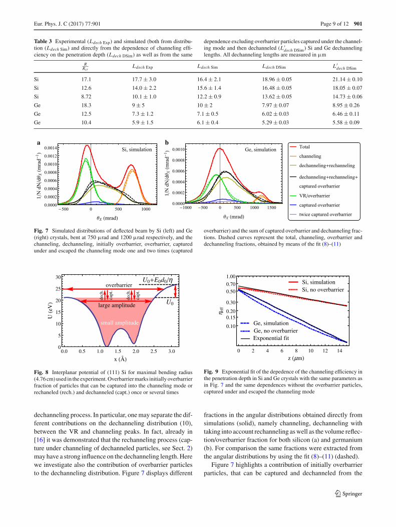
Table 3 Experimental (Ldech Exp) and simulated (both from distribu-tion (Ldech Sim) and directly from the dependence of channeling effi-ciency on the penetration depth (Ldech DSim) as well as from the same
dependence excluding overbarrier particles captured under the channel-ing mode and then dechanneled (L ′
dech DSim) Si and Ge dechannelinglengths. All dechanneling lengths are measured in µm
RRcr
Ldech Exp Ldech Sim Ldech DSim L ′dech DSim
Si 17.1 17.7 ± 3.0 16.4 ± 2.1 18.96 ± 0.05 21.14 ± 0.10
Si 12.6 14.0 ± 2.2 15.6 ± 1.4 16.48 ± 0.05 18.05 ± 0.07
Si 8.72 10.1 ± 1.0 12.2 ± 0.9 13.62 ± 0.05 14.73 ± 0.06
Ge 18.3 9 ± 5 10 ± 2 7.97 ± 0.07 8.95 ± 0.26
Ge 12.5 7.3 ± 1.2 7.1 ± 0.5 6.02 ± 0.03 6.46 ± 0.11
Ge 10.4 5.9 ± 1.5 6.1 ± 0.4 5.29 ± 0.03 5.58 ± 0.09
a b
Fig. 7 Simulated distributions of deflected beam by Si (left) and Ge(right) crystals, bent at 750 µrad and 1200 µrad respectively, and thechanneling, dechanneling, initially overbarrier, overbarrier, capturedunder and escaped the channeling mode one and two times (captured
overbarrier) and the sum of captured overbarrier and dechanneling frac-tions. Dashed curves represent the total, channeling, overbarrier anddechanneling fractions, obtained by means of the fit (8)–(11)
small amplitude
large amplitude
dech.
capt.
dech.
capt.
overbarrier
U0
U0 E0d0 η
0.0 0.5 1.0 1.5 2.0 2.5 3.00
5
10
15
20
25
30
x Å
UeV
Fig. 8 Interplanar potential of (111) Si for maximal bending radius(4.76 cm) used in the experiment. Overbarrier marks initially overbarrierfraction of particles that can be captured into the channeling mode orrechaneled (rech.) and dechanneled (capt.) once or several times
dechanneling process. In particular, one may separate the dif-ferent contributions on the dechanneling distribution (10),between the VR and channeling peaks. In fact, already in[16] it was demonstrated that the rechanneling process (cap-ture under channeling of dechanneled particles, see Sect. 2)may have a strong influence on the dechanneling length. Herewe investigate also the contribution of overbarrier particlesto the dechanneling distribution. Figure 7 displays different
Si, simulationSi, no overbarrier
Ge, simulationGe, no overbarrierExponential fit
0 2 4 6 8 10 12 14
0.10
1.00
0.50
0.20
0.30
0.15
0.70
z μm
η eff
Fig. 9 Exponential fit of the depedence of the channeling efficiency inthe penetration depth in Si and Ge crystals with the same parameters asin Fig. 7 and the same dependences without the overbarrier particles,captured under and escaped the channeling mode
fractions in the angular distributions obtained directly fromsimulations (solid), namely channeling, dechanneling withtaking into account rechanneling as well as the volume reflec-tion/overbarrier fraction for both silicon (a) and germanium(b). For comparison the same fractions were extracted fromthe angular distributions by using the fit (8)–(11) (dashed).
Figure 7 highlights a contribution of initially overbarrierparticles, that can be captured and dechanneled from the
123

901 Page 10 of 12 Eur. Phys. J. C (2017) 77 :901
a b
Fig. 10 Theoretical, experimental and simulated dependence of the maximal value of volume reflection peak position w.r.t. the Lindhard angle onthe bending radius w.r.t. its critical value for both Si and Ge (111) bent crystals
channeling mode several times (marked in Fig. 7 as rechan-neled ovebarrier). In a bent crystal, the contribution of over-barrier particle cannot be eliminated, even considering a par-allel beam. Indeed, due to the asymmetry in the potential bar-rier introduced by the bending, particles approaching withzero transverse kinetic energy to the right potential barrierare reflected to the left, gaining a non-zero transverse kineticenergy. A sketch of initially overbarrier particles is depictedin Fig. 8; such particles follow the bent crystal planes andcan be deflected to a considerable angle.
The solid black line in Fig. 7 represents the contribution ofdechanneled and rechanneled particles with the contributionof captured overbarrier particles. If compared with the dottedsolid black line, representing the result of the fit (8)–(11), itis clear that from the experimental deflection distribution isnot possible to extract a dechanneling length correspondentto only initially channeled particles. By this reason the fit[17,18] was modified to (8)–(11).
To highlight deeply the contribution of captured overbar-rier particles, channeling efficiency was also simulated in adependence on the penetration depth z, taking (solid) andnot taking (dashed) into account this contribution for bothSi (red) and Ge (blue) crystals as shown in Fig. 9. By usingan exponential fit (4) the values of dechanneling length wereextracted (see Table 3, Ldech DSim and L ′
dech DSim , for thecases with and without captured overbarriers, respectively).The values Ldech DSim differ from the extracted ones fromexperimental and simulated angular distributions, no morethan on ∼ 1–2 µm, lying usually within the frame of theerror.
On the contrary, the simulated dechanneling length with-out the contribution of captured overbarrier particles,L ′dech DSim , (see Table 3), exceed Ldech DSim by 5–10%.
In other words, the initially overbarrier particles decreasethe total dechanneling length by several percent because canusually be captured slightly below the potential well bar-rier, as shown in Fig. 8. Since these large amplitude particlesdechannel faster, the dechanneling length of these particlesis lower than for the stable ones. Consequently, the captureof initially overbarrier particles reduce the total measured
dechanneling length. Furthermore, even if these values wereobtained in the same way as Ldech DSim , the dependence ofL ′dech DSim on the penetration depth evidently differ from
the exponent function. Indeed, one has to remember that thedechanneling of negative particles is mainly due to strongscattering with nuclei that has an intrinsic non-slow diffu-sive nature [37].
The relative difference between L ′dech DSim and
Ldech DSim increases with crystal radius rise. This is explainedby decreasing of the difference E0d0/η(η = R/Rc, seeSect. 2) between the right and left potential barriers. Conse-quently such overbarrier particles are closer to the potentialboundary. This means that such particles will remain nearthe potential barrier for a longer distance due to low trans-verse velocities, having the influence on the total dechan-nelling length also for a longer distance at higher radius val-ues. Therefore, initially ovebarrier particles, captured underchanneling mode and then dechanneled, can make a severalpercent contribution into dechanneling length value.
Finally, we also investigated the other mechanism of beamdeflection, i.e., the VR. In particular we studied VR deflec-tion angle vs. the curvature radius, while comparing to themaximal angle expected from the theory (6)–(7).
In order to verify the theoretical dependence of the maxi-mal angle of VR on R (see Eqs. 6–7), we used the experimen-tal and simulated values for the modules of a maximal VRangle (determined by gaussian fit) comparing them in Fig.10. For channeling deflection angle, the agreement betweentheory and both experimental and simulated results is verygood for silicon, while being worse for germanium. This factis explained again by the contribution of multiple scatteringof non-volume reflected particles, allocated around 0 angle(see Figs. 3, 4), that shifts the volume reflection peak centertowards 0 on the angular distribution. Multiple scattering hasa much stronger influence for germanium, for which its r.m.s.angle is 2.2 times higher than for silicon. By this reason themeasured maximum VR for silicon of 235 µrad is about θLangle for silicon (in agreement with previous experiments[16,19]), while it is only 0.6θL for germanium, being equalto 178 µrad.
123
Eur. Phys. J. C (2017) 77 :901 Page 11 of 12 901
5 Conclusions
An experiment on beam steering of 855 MeV electrons byusing 15 µm bent silicon and germanium crystals has beencarried out at the Mainzer Mikrotron. Through the exploita-tion of an innovative piezo-actuated mechanical bender, itwas possible to test planar channeling and volume reflectionfor several radii of curvature.
Experimental results, in agreement with Monte Carlo sim-ulation, demonstrated that maximum channeling efficiencywere about 40% and 8% for silicon and germanium, respec-tively. The difference between these two materials has to beascribed to the higher atomic number Z for Ge, which resultsin a higher Coulomb scattering contribution, causing strongerdechanneling. Indeed, we also measured the main parame-ter of planar channeling, i.e., the dechanneling length, whichresulted to be close to the crystal length for Si, but 2 timesshorter for the Ge crystal at the largest bending radius. In par-ticular, the usage of a Si crystal with the length comparableto the dechanneling length permitted an unprecedented levelof steering efficiency for an electron beam.
On the other hand, it is important to remark that any mea-surements of a negatively charged beam steering in a ger-manium bent crystal at the energies lower than hundreds ofGeV have never been done before, due to the lack of prop-erly designed crystals, i.e. with a length of the order of thedechanneling length. Therefore, the evidence of beam steer-ing of sub-GeV electrons in a Ge crystal was demonstratedfor the first time.
We also highlighted the influence of initially non-channeledparticles on the dechanneling processes, which causes areduction of the dechanneling length in case the crystal thick-nesses are comparable with the dechanneling length.
Finally, we investigated dependence of the ratio betweenthe volume reflection angle and the Lindard angle vs. theR/Rc (see Eqs. (6)–(7)), demonstrating that it does notdepend on the energy, being very useful to make predictionat different energies.
The presented results, in particular the studies of beamefficiency and dechanneling length vs. the crystal curva-ture and atomic number, are of interest for application, suchas generation of e.m. radiation in higher Z-materials bent[15,27,54] and periodically bent crystals [55–59]. Given thegood agreement with Monte Carlo simulation, one may alsothink to apply the presented approach to extrapolate infor-mation on charged particle steering at higher energies, forinstance to investigate the possibility of crystal-based col-limation/extraction at current and future electrons accelera-tors.
Acknowledgements We acknowledge partial support by the EuropeanCommission through the PEARL Project within the H2020-MSCA-RISE-2015 call, GA n. 690991 and by the INFN-AXIAL experiment.
We also acknowledge the CINECA award under the ISCRA initiative forthe availability of high performance computing resources and support.E. Bagli, L. Bandiera and A. Mazzolari recognize the partial support ofFP7-IDEAS-ERC CRYSBEAM project GA n. 615089. We acknowl-edge Professor H. Backe for fruitful discussions and M.Rampazzo, A.Pitacco and A. Minarello for technical assistance in dynamic holderrealization.
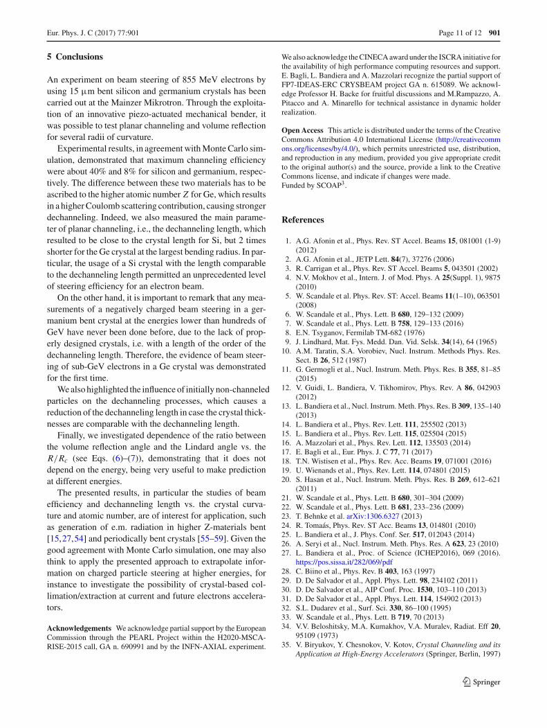
Open Access This article is distributed under the terms of the CreativeCommons Attribution 4.0 International License (http://creativecommons.org/licenses/by/4.0/), which permits unrestricted use, distribution,and reproduction in any medium, provided you give appropriate creditto the original author(s) and the source, provide a link to the CreativeCommons license, and indicate if changes were made.Funded by SCOAP3.
References
1. A.G. Afonin et al., Phys. Rev. ST Accel. Beams 15, 081001 (1-9)(2012)
2. A.G. Afonin et al., JETP Lett. 84(7), 37276 (2006)3. R. Carrigan et al., Phys. Rev. ST Accel. Beams 5, 043501 (2002)4. N.V. Mokhov et al., Intern. J. of Mod. Phys. A 25(Suppl. 1), 9875
(2010)5. W. Scandale et al. Phys. Rev. ST: Accel. Beams 11(1–10), 063501
(2008)6. W. Scandale et al., Phys. Lett. B 680, 129–132 (2009)7. W. Scandale et al., Phys. Lett. B 758, 129–133 (2016)8. E.N. Tsyganov, Fermilab TM-682 (1976)9. J. Lindhard, Mat. Fys. Medd. Dan. Vid. Selsk. 34(14), 64 (1965)
10. A.M. Taratin, S.A. Vorobiev, Nucl. Instrum. Methods Phys. Res.Sect. B 26, 512 (1987)
11. G. Germogli et al., Nucl. Instrum. Meth. Phys. Res. B 355, 81–85(2015)
12. V. Guidi, L. Bandiera, V. Tikhomirov, Phys. Rev. A 86, 042903(2012)
13. L. Bandiera et al., Nucl. Instrum. Meth. Phys. Res. B 309, 135–140(2013)
14. L. Bandiera et al., Phys. Rev. Lett. 111, 255502 (2013)15. L. Bandiera et al., Phys. Rev. Lett. 115, 025504 (2015)16. A. Mazzolari et al., Phys. Rev. Lett. 112, 135503 (2014)17. E. Bagli et al., Eur. Phys. J. C 77, 71 (2017)18. T.N. Wistisen et al., Phys. Rev. Acc. Beams 19, 071001 (2016)19. U. Wienands et al., Phys. Rev. Lett. 114, 074801 (2015)20. S. Hasan et al., Nucl. Instrum. Meth. Phys. Res. B 269, 612–621
(2011)21. W. Scandale et al., Phys. Lett. B 680, 301–304 (2009)22. W. Scandale et al., Phys. Lett. B 681, 233–236 (2009)23. T. Behnke et al. arXiv:1306.6327 (2013)24. R. Tomaás, Phys. Rev. ST Acc. Beams 13, 014801 (2010)25. L. Bandiera et al., J. Phys. Conf. Ser. 517, 012043 (2014)26. A. Seryi et al., Nucl. Instrum. Meth. Phys. Res. A 623, 23 (2010)27. L. Bandiera et al., Proc. of Science (ICHEP2016), 069 (2016).
https://pos.sissa.it/282/069/pdf28. C. Biino et al., Phys. Rev. B 403, 163 (1997)29. D. De Salvador et al., Appl. Phys. Lett. 98, 234102 (2011)30. D. De Salvador et al., AIP Conf. Proc. 1530, 103–110 (2013)31. D. De Salvador et al., Appl. Phys. Lett. 114, 154902 (2013)32. S.L. Dudarev et al., Surf. Sci. 330, 86–100 (1995)33. W. Scandale et al., Phys. Lett. B 719, 70 (2013)34. V.V. Beloshitsky, M.A. Kumakhov, V.A. Muralev, Radiat. Eff 20,
95109 (1973)35. V. Biryukov, Y. Chesnokov, V. Kotov, Crystal Channeling and its
Application at High-Energy Accelerators (Springer, Berlin, 1997)
123

901 Page 12 of 12 Eur. Phys. J. C (2017) 77 :901
36. V. Baier, V. Katkov, V. Strakhovenko, Electromagnetic Processesat High Energies in Oriented Single Crystals (World Scientific,Singapore, 1998)
37. V.V. Tikhomirov, Eur. Phys. J. C 77, 483 (2017)38. H. Backe et al., Nucl. Instrum. Meth. Phys. Res. B 266, 3835–3851
(2008)39. H. Backe et al., Nucl. Instrum. Meth. Phys. Res. B 309, 37 (2013)40. H. Backe, W. Lauth, Nucl. Instrum. Meth. Phys. Res. B 355, 24–29
(2015)41. V.A. Maisheev, Phys. Rev. STAB 10, 084701 (2007)42. S. Bellucci et al., Phys. Rev. STAB 18, 114701 (2015)43. A. I. Sytov, V. V. Tikhomirov, A. S. Lobko Phys. Rev. Acc. and
Beams, 20, 071001 (2017)44. E. Bagli et al., Proc. of IPAC’10, THPEC080, 4243 (2010)45. Y.M. Ivanov, A.A. Petrunin, V.V. Skorobogatov, JETP Lett. 81, 99
(2005)46. R. Camattari, V. Guidi, V. Bellucci, A. Mazzolari, J.
Appl. Cryst. 107, 064102-1–5 (2015). https://doi.org/10.1107/S1600576715009875
47. Guidi et al., J. Phys. D: Appl. Phys. 42, 182005 (2009)48. D. Lietti et al., Rev. Sci. Instrum. 86, 045102 (2015)
49. A.I. Sytov, V.V. Tikhomirov, Nucl. Instrum. Meth. Phys. Res. B355, 383–386 (2015)
50. A.I. Sytov, Vestnik of the Bel. St. Univ. Ser. 1(2), 48–52 (2014)51. T.N. Wistisen et al., Phys. Rev. Lett. 119, 024801 (2017)52. E. Bagli et al., Eur. Phys. J. C 74, 2740 (2014)53. C. Patrignani et al., Particle Data Group. Chin. Phys. C 40, 100001
(2016)54. L. Bandiera, E. Bagli, V. Guidi, V.V. Tikhomirov, Nucl. Instrum.
Meth. Phys. Res. B 355, 44–48 (2015). https://doi.org/10.1016/j.nimb.2015.03.031
55. V.G. Baryshevsky, I.Ya. Dubovskaya, A.O. Grubich, Phys. Lett.77A, 61 (1980)
56. A.V. Korol, A.V. Solov’yov, W. Greiner, Int. J. Mod. Phys. E 13,867 (2004). https://doi.org/10.1142/S0218301304002557
57. E. Bagli et al., Eur. Phys. J. C 74, 3114 (2014)58. A. Kostyuk, Phys. Rev. Lett. 110, 115503 (2013)59. T.N. Wistien et al., Phys. Rev. Lett. 112, 254801 (2014)
123